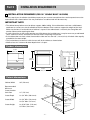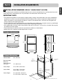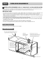
1
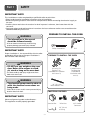
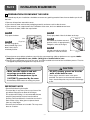
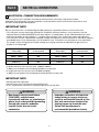
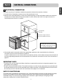
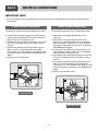
ENGLISH
ESPAÑOL
FRANÇAIS
INSTALLATION MANUAL
ELECTRIC CONVECTION
BUILT-IN OVEN
Please read these instructions thoroughly before
installing and operating the oven.
LWS3081ST
LWD3081ST
LSWS305ST
P/No.: MFL51224801
LSWD305ST
LWS3010ST
LWD3010ST
www.lge.com
Part 1
SAFETY
1 BEFORE YOU BEGIN
Remove all tape and packing materials before using the oven. Dispose all plastic bags after unpacking the oven.
Never allow children to play with packing materials.
IMPORTANT SAFETY INSTRUCTIONS
Read and follow all instructions before using your oven to prevent the risk of fire, electric shock, injury to person,
or damage when using the oven. This guide does not cover all possible conditions that may occur. For further
assistance contact your service agent or manufacturer.
This is the safety alert symbol. This symbol alerts you to potential hazards that can kill or hurt you and
others. All safety messages will follow the safety alert symbol and either the word “WARNING” or
“CAUTION”. These words mean :
WARNING
This symbol will alert you to hazards or unsafe practices which could cause serious bodily
harm or death.
CAUTION
This symbol will alert you to hazards or unsafe practices which could cause bodily injury or
property damage.
WARNING
• The information in this manual should be followed exactly.
- A fire or electrical shock may result causing property damage, personal injury or death.
• DO NOT put any weight on the oven door. Never allow anyone to climb, sit, stand or
hang on the oven door.
- The oven could be tipped and injury might result from food or the oven itself.
• The electrical power must be shut off while the electrical connections are being
made.
- Failure to do so can result in severe personal injury, death or electrical shock.
• New branch-circuit installations (1996 NEC), mobile homes, recreational vehicles, or
installations where local codes prohibit grounding through the neutral conductor
require 4-wire branch-circuit connection.
• Improper connection of aluminum house wiring to copper leads can result in an
electrical hazard or fire. Use only connectors designed for joining copper to
aluminum and follow the manufacturer’s recommended procedure closely.
• Mounting screws must be used.
- Failure to do so can result in the oven falling out of the cabinet causing serious injury.
CAUTION
Make sure the cabinets and wall coverings around the oven can withstand the
temperature (up to 194˚F[90˚C]) generated by the oven.
- Discoloration, delamination or melting may occur.
• DO NOT remove spacers on the side walls of the built-in oven.
- These spacers center the oven in the space provided.The oven must be centered to prevent
excess heat buildup that may result in heat damage or fire.
• DO NOT block the oven air exhaust located at the bottom of the oven.
- Blocking the exhaust may cause cabinet damage and product malfunction.
•
-2-
Part 1
SAFETY
This installation must be completed by a qualified installer or technician.
• Please read the entire Installation Instructions prior to installation.
• Remove all packing materials from the oven compartments before connecting the electrical supply to
the oven.
• Installer: please retain these instructions for local inspector’s reference, then leave them with the
consumer.
• Consumer: please read and keep these instructions for future reference and be sure to read the entire
OWNER’S MANUAL prior to use.
PREPARE TO INSTALL THE OVEN
WARNING
• The information in this manual
should be followed exactly.
- A fire or electrical shock may result causing
property damage, personal injury or death.
Phillips Screwdriver
IMPORTANT NOTE
Proper installation is the responsibility of the installer
and product failure due to improper installation is
NOT covered under warranty.
Drill
PREPARE TO INSTALL THE OVEN
WARNING
• DO NOT put any weight on the oven
door. Never allow anyone to climb,
sit, stand or hang on the oven door.
6 Screws For
Bottom Trim
(3 needed for installation
and 3 extra’s)
- The oven could tip and injury might result from
food or the oven itself.
6 Wood Screws
For Mounting
(4 needed for
installation and 2
extra’s)
WARNING
• The electrical power must be shut off
while the electrical connections are
being made.
30” (76.2 cm)
Metal Bottom Trim
- Failure to do so can result in severe personal injury,
death or electrical shock.
MATERIALS NEEDED
IMPORTANT NOTE
Observe all governing codes and ordinances.
This appliance must be properly grounded.
Junction Box
Wire Nuts
36” (91 cm)
of String
-3-
3/4” Conduit
Connector
ENGLISH
IMPORTANT NOTE
Part 2
INSTALLATION REQUIREMENTS
1 INSTALLATION DRAWINGS (FOR 30” SINGLE BUILT- IN OVEN)
The first step of your installation should be to measure your current cutout dimensions and compare them to the
cutout dimensions shown below. You may find little or no cabinet work will be necessary.
IMPORTANT NOTE
• The cabinet base platform must be able to support 190lbs (86Kg). If the cabinet does not have a solid bottom,
two braces or runners must be installed level with the bottom of the cutout to support the weight of the oven.
Make sure the base is level and front of cabinet is square. If the cabinet base is not level, the oven glides will
tend to slide out when opening the door.
• If marks, blemishes or the cutout opening are visible above the installed oven, it may be necessary to add wood
shims under the runners and front trim until the marks or opening are covered.
• If the cabinet does not have a front frame and the sides are less than 3/4” (1.9 cm) thick, shim both sides equally
to establish the cutout width.
• The junction box must be flush with the rear wall of the cabinet as shown below.
• Allow at least 23” clearance for door depth when it is open.
Product dimensions
27 3/8”
(69.5 cm)
29 5/16”
(74.5 cm)
28 7/8”
(73.3 cm)
29 3/4”
(75.5 cm)
23 3/8”
(59.3 cm)
Cutout dimensions
30”
Cabinet Width
Recommended
Minimum
Cutout location
from floor
30” (762 mm)
Allow 1”
minimum for
overlap of oven
5”
28 1/2” Min.
28 5/8” Max.
Junction Box
Location
31” (787.4 m)
23 1/2”
Cutout Depth
23 1/2” Min. (596.9 mm)
Cutout Width
28 1/2” Min. (723.9 mm)
28 5/8” Max. (727 mm)
Cutout Height
28 15/16” Min. (735 mm)
29” Max. (736.6 mm)
23”
28 15/16” Min.
29” Max.
23 1/2”
Allow 1”
minimum for
overlap of oven
-4-
Minimum cutout
location from
floor 31”
Part 2
INSTALLATION REQUIREMENTS
The first step of your installation should be to measure your current cutout dimensions and compare them to the
cutout dimensions shown below. You may find little or no cabinet work will be necessary.
IMPORTANT NOTE
• The cabinet base platform must be able to support 325lbs (147Kg). If the cabinet does not have a solid bottom,
two braces or runners must be installed level with the bottom of the cutout to support the weight of the oven.
Make sure the base is level and front of cabinet is square. If the cabinet base is not level, the oven glides will
tend to slide out when opening the door.
• If marks, blemishes or the cutout opening are visible above the installed oven, it may be necessary to add wood
shims under the runners and front trim until the marks or opening are covered.
• If the cabinet does not have a front frame and the sides are less than 3/4” (1.9 cm) thick, shim both sides equally
to establish the cutout width.
• The junction box must be flush with the rear wall of the cabinet as shown below.
• Allow at least 23” clearance for door depth when it is open.
Product dimensions
27 3/8”
(69.5 cm)
52 1/16”
(132.2 cm)
51 5/8”
(131.0 cm)
29 3/4”
(75.5 cm)
Cutout dimensions
Cabinet Width
30”
30” (762 mm)
Allow 1”
minimum for
overlap of oven
Recommended
Minimum
Cutout location
from floor
12” (304.8 mm)
Cutout Depth
23 1/2” Min. (596.9 mm)
Cutout Width
28 1/2” Min. (723.9 mm)
28 5/8” Max. (727 mm)
Cutout Height
51 13/16” Min. (1316 mm)
51 15/16” Max. (1319.2 mm)
23 3/8”
(59.3 cm)
5”
28 1/2” Min.
28 5/8” Max.
Allow 1”
minimum for
overlap of oven
Junction Box
Location
51 13/16” Min.
51 15/16” Max.
47”
23”
23 1/2”
Minimum cutout location from floor 12”
-5-
ENGLISH
2 INSTALLATION DRAWINGS (FOR 30” DOUBLE BUILT- IN OVEN)
Part 2
INSTALLATION REQUIREMENTS
3 INSTALLATION DRAWINGS (FOR 30” SINGLE BUILT- IN OVEN UNDERCOUNTER)
The first step of your installation should be to measure your current cutout dimensions and compare them to the
cutout dimensions shown below. You may find little or no cabinet work will be necessary.
IMPORTANT NOTE
• The cabinet base platform must be able to support 190lbs (86Kg). If the cabinet does not have a solid bottom, two
braces or runners must be installed level with the bottom of the cutout to support the weight of the oven.
Make sure the base is level and front of cabinet is square. If the cabinet base is not level, the oven glides will tend
to slide out when opening the door.
• If marks, blemishes or the cutout opening are visible above the installed oven, it may be necessary to add wood
shims under the runners and front trim until the marks or opening are covered.
• If the cabinet does not have a front frame and the sides are less than 3/4” (1.9 cm) thick, shim both sides equally
to establish the cutout width.
• The junction box must be flush with the rear wall of the cabinet as shown below.
• This oven is only approved to be installed under the specific models as labeled on this unit.
Product dimensions
Dimensions are same as the single built-in oven on page 4.
Cutout dimensions
Gas or electric cooktops may be installed over this oven.
See cooktop installation instructions for cutout size.
See label on top of oven for approved cooktop models.
25” (63.5 cm)
240V / 208V
Junction Box Location
(Junction box may be
in adjacent cabinet)
Gas and electrical connections for
30” (76.2 cm) gas cooktop must be located
in an adjacent accessible location to the
right. For a 36” (91.4 cm) gas cooktop, the
connections may be made to the left.
5”
Top and/or side fillers
may be necessary if
unit is positioned
between existing
cabinets. Be sure they
are attached securely
since, they will anchor
the oven in the cabinets.
28 15/16” (73.5 cm) Min.
29” (73.7 cm) Max.
Allow 1” (2.5 cm)
overlap top of oven,
1 1/16” (1.8 cm) overlap
side edges of cutout
and 1 1/4” (3.2 cm)
overlap bottom of oven.
23 1/2” (59.7cm) Min.
Above Support
Platform
36” (91.4cm)
Typical
Countertop
Height
28 1/2” (72.4 cm) Min.
28 5/8” (72.7 cm) Max.
24” (61 cm)
4” (10.2 cm) Typical Toekick
-6-
Part 2
INSTALLATION REQUIREMENTS
The second step of your installation should be to remove any packing material from the oven before you install
the oven.
1. Remove all tape from around the oven.
2. Open the oven door and remove packaging materials and oven racks inside the oven.
3. Door removal is not a requirement for installation of the oven, but is an added convenience.
To remove the door, follow the steps below.
Step. 1
Step. 3
Fully open the door.
Slot
Step. 2
Firmly grasp both sides of the door at the top.
Lock
Unlock
Close door to the door removal
position, which is approximately
5 degrees. (refer to the Fig.2)
Hinge lock
Pull the hinge locks
down toward (Fig.1) the
door frame, to the
unlocked position.
about 5˚
Step. 4
Step. 5
<Fig.1>
Lift door up and out until the
hinge arm is clear of the slot.
<Fig.2>
4. Place the oven on a table or platform even with the cutout opening. (table or platform must support 190lbs
[86Kg] for a single built-in oven, 325lbs [147Kg] for a double built-in oven.
5. Remove the metal bottom trim from the oven. It will be installed at the end of the installation process. The trim
is wrapped separately and taped to the top of the unit.
CAUTION
CAUTION
• Make sure the cabinets and wall
coverings around the oven can
withstand the temperature (up to
194˚F[90˚C]) generated by the oven.
• DO NOT remove spacers on the side
walls of the built-in oven.
- These spacers center the oven in the space
provided. The oven must be centered to prevent
excess heat buildup that may result in heat damage
or fire.
- Discoloration, delamination or melting may occur.
IMPORTANT NOTE
• Do not lift the door by the handle.
• The oven door is very heavy. Be sure you have a firm
•
grip before lifting the oven door off the hinges.
Use caution when lifting. It is recommended that two
people lift and position the oven into the cabinet
opening. Failure to follow this instruction can result in
back or other injury. Wear gloves to protect hands
from any sharp edges.
Do not lay the oven door on its handle. This may cause
dents or scratches.
Spacer
-7-
ENGLISH
4 PREPARATION FOR MOVING THE OVEN
Part 3
ELECTRICAL CONNECTIONS
1 ELECTRICAL CONNECTION REQUIREMENTS
The third step of your installation should be to follow electrical connection requirements below.
Dedicated circuit protection must be prepared as recommended in electrical connection requirements and
the oven should be grounded properly.
IMPORTANT NOTE
Be sure your wall oven is installed and grounded properly by a qualified installer or service technician.
• This wall oven must be electrically grounded in accordance with local codes or, in their absence, with the
National Electrical Code ANSI/NFPA No.70- latest edition* in United States, or with CSA Standard C22.1-1982
and C22.2 No.01982 (or latest edition)**, Canadian Electrical Code, Part1, and all local codes and ordinances.
• This wall oven must be supplied with the proper voltage and frequency, and connected to an individual, properly
grounded branch circuit, protected by a circuit breaker or fuse. To know the circuit breaker or fuse required by
this model, see the rating plate to find the wattage consumption and refer to table below to get the circuit
breaker or fuse amperage.
Appliance Rating
Watts 240V
less than 4800W
Protection Circuit
recommended
Protection Circuit
recommended
20A
Appliance Rating
Watts 208V
less than 4100W
4800W - 7200W
30A
4100W - 6200W
30A
7200W - 9600W
40A
6200W - 8300W
40A
9600 and +
50A
8300 and +
50A
20A
• A double wall oven can consume up to 7,800W at 240VAC.
A 40Amp circuit breaker with wire gauge #8 AWG must be used.
• A single wall oven can consume up to 4,100W at 240VAC.
A 30Amp circuit breaker with wire gauge at least #10 AWG must be used.
IMPORTANT NOTE
• Do Not ground to a gas pipe.
• Do Not have a fuse in the neutral or grounding circuit.
• A U.L.-listed conduit connector must be provided at the junction box.
WARNING
WARNING
• New branch-circuit installations
(1996 NEC), mobile homes,
recreational vehicles, or installations
where local codes prohibit grounding
through the neutral conductor
require 4-wire branch-circuit
connection.
• Improper connection of aluminum
house wiring to copper leads can
result in an electrical hazard or fire.
Use only connectors designed for
joining copper to aluminum and
follow the manufacturer’s
recommended procedure closely.
-8-
Part 3
ELECTRICAL CONNECTIONS
The fourth step of your installation should be to prepare the electrical connection as follows:
1. Turn off the circuit breaker or remove fuses to the oven branch circuit.
2. With the oven positioned directly in front of the cabinet opening, connect the flexible conduit to the electrical
junction box as shown below. Position the conduit in such a manner that it will lie on top of the oven in a
natural loop when the oven is installed.
5” Min
Junction Box
Location
22” Min for single wall oven
42” Min for double wall oven
Junction Box must be recessed
and conduit connector must be
used at Junction Box.
3. If local codes permit connection of the frame grounding conductor to the neutral(white) wire, follow the
instruction of 3-wire circuit connection on page 10.
If used in mobile homes or new construction, or recreational vehicle, or local codes do not permit connection of
the frame grounding conductor to the neutral(white) wire, follow the instruction of 4-wire circuit connection on
page 10.
IMPORTANT NOTE
• The wall ovens must be hard wired (direct wired) into an approved junction box. A plug and receptacle is not
permitted on these products.
• DO NOT shorten the flexible conduit. The conduit connector must be securely attached to the junction box and
the flexible conduit must be securely attached to the conduit connector. If the flexible conduit will not fit within
the connector, do not install the oven until a connector of the proper size is obtained.
NOTE TO ELECTRICIAN
The power leads supplied with the appliance are UL, CSA recognized for connection to larger gauge household
wiring. The insulation of these leads is rated at temperatures much higher than the temperature rating of
household wiring. The current carrying capacity of the conductor is governed by the wire gauge and the
temperature rating of the insulation around the wire.
-9-
ENGLISH
2 ELECTRICAL CONNECTION
Part 3
ELECTRICAL CONNECTIONS
IMPORTANT NOTE
• You will need to purchase an appropriate conduit connector to complete the connection of the conduit to the
junction box.
3-wire circuit connection
4-wire circuit connection
To connect to a three-wire circuit, follow these steps:
To connect to a four-wire circuit, follow these steps:
1. Connect the oven ground (green) wire and neutral
(white) wire to the branch circuit neutral (white or
gray in color) wire, using a wire nut.
2. Connect the oven red wire to the branch circuit red
(L2) wire in accordance with local codes, using a
wire nut.
3. Connect the oven black wire to the branch circuit
black (L1) wire in accordance with local codes,
using a wire nut. If the residence red, black or white
wires are aluminum conductors, see WARNING on
page 8.
4. Install the junction box cover.
1. Separate the oven ground and white wires if
necessary.
2. Connect the oven ground (green) wire to the
branch circuit ground (green) wire in accordance
with local codes, using a wire nut. If the residence
red, black or white wires are aluminum conductors,
see WARNING on page 8.
3. Connect the oven white wire to the branch circuit
neutral (white or gray in color) wire in accordance
with local codes, using a wire nut.
4. Connect the oven red wire to the branch circuit red
(L2) wire in accordance with local codes, using a
wire nut.
5. Connect the oven black wire to the branch circuit
black (L1) wire in accordance with local codes,
using a wire nut. If the residence red, black or white
wires are aluminum conductors, see WARNING on
page 8.
6. Install the junction box cover.
Neutral
White
Green
Red
Black
Wire nut
White
Green
Neutral
Red
Black
Junction Box
Wire nut
Junction Box
- 10 -
Part 4
INSTALL THE OVEN
ENGLISH
1 CABINET INSTALLATION
The fifth step of your installation should be to install the oven into the cabinet as follows:
1. Sliding the oven into the opening.
a. Loop (do not tie) a 36” (91cm) string around the conduit before the oven is slid into place.This will keep the
conduit from falling behind the oven.
b. Lift oven into cabinet cutout using the oven opening as a grip. Carefully push against the oven front frame.
Do not push against outside edges.
c. As you slide the oven back, pull the string so that the conduit will lie on the top of the oven in a natural loop.
d. When you are sure the conduit is out of the way, slide the oven 3/4 way back into the opening. Remove the
string by pulling on one end of the loop.
WARNING
CAUTION
• Mounting screws must be used.
• DO NOT block the oven air exhaust
located at the bottom of the oven.
- Failure to do so can result in the oven falling out
of the cabinet causing serious injury.
- Blocking the exhaust may cause cabinet damage
and product malfunction.
2. Securing the oven.
a. Using the mounting holes on the oven side trim as
a guide, drill pilot holes for screws provided (For
securing the double wall oven, use a minimum of
4 screws, one on each side in both the upper and
lower ovens. For securing the single wall oven,
use a minimum of 2 screws, one on each side.)
b. Secure the oven to cabinet with screws provided.
If the cabinet is particle board, you must use 3/4”
particle board screws. These may be purchased at
any hardware store.
3. Installing the metal bottom trim.
a. Place the metal bottom trim centered over the pre
drilled mounting holes on the lower base.
b. Using 3 screws provided, secure the bottom trim
to the bottom edge of the cabinet.
4. Reinstalling the oven door.
Trim Screws
Mounting
Hole
Locations
Side
Trim
Side
Trim
Metal
bottom trim
Lower base
Mounting
Hole
Locations
Step. 1
Step. 3
Firmly grasp both
sides of the door
at the top.
Fully open the door. If the door will not fully open, the
indentation is not seated correctly in the bottom edge
of the slot.
Step. 2
Step. 4
With the door at
Hinge arm
the same angle as
the removal
position, seat the
Bottom
indentation of the
edge of
slot
hinge arm into the
bottom edge of the
Indentation
hinge slot. The notch
in the hinge
arm must be fully seated into the bottom of the slot.
Push the hinge locks up
against the front frame of the
oven cavity to the locked
position.
Step. 5
Close the oven door.
- 11 -
Hinge arm
Hinge lock
Part 5
OPERATION CHECKLIST
1 CHECKING OPERATION
Each of the functions has been factory checked before shipping. However, it is suggested that you verify the
operation of the oven once more. Refer to the Owner’s Manual. Follow the instructions for the basic check.
1. Turn on power supply. The initial signal sound will be heard and LG logo should be appear in the display.
2. Check the operation of the broil mode. When the oven is set to broil, the upper element in the oven should
become red. After few minutes, partially open the oven door. You should feel heat from the oven. Press the
“CLEAR/OFF” pad.
3. Check the operation of the bake mode. After setting the oven to 350˚F/177˚C for baking, the temperature of the
oven in the display should increase. Press the “CLEAR/OFF” pad.
4. Check the operation of the convection bake mode. After setting the oven to 350˚F/177˚C for convection baking,
the fan inside the oven should come on with the door closed. Press the “CLEAR/OFF” pad.
5. Turn on and off the oven light to check the lights are normal condition.
6. Check the operation of the furnace convection mode. After setting the oven to 350˚F/177˚C for the furnace
convection mode, the back element should light up and the fan inside the oven should come on with door
closed.
IMPORTANT NOTE
• A small amount of smoke and odor may be noticed during the initial break-in period.
• If your oven does not operate properly or an “F”, followed by a number, appears in the display, see your
Owner’s Manual for troubleshooting list. The list includes common occurrences that are not the result of
defective workmanship or materials in this product. If the problem occurs continuously, contact your dealer.
• Refer to the warranty in your Owner’s Manual for our tool-free service number and address.
- 12 -
LG Customer Information Center
1-800-243-0000 USA, Consumer User
1-888-865-3026 USA, Commercial User
1-888-542-2623 CANADA
Register your product Online!
www.lg.com
Printed in Korea