1
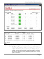
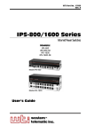
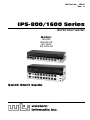
WTI Part No.: 13502
Rev.: A
IPS-800/1600 Series
Internet Power Switches
Models:
IPS-800
IPS-800-CE
IPS-1600
IPS-1600-CE
Quick Start Guide
Warnings and Cautions:
Installation Instructions
Secure Racking
If Secure Racked units are installed in a closed or multi-unit rack assembly, they may require further
evaluation by Certification Agencies. The following items must be considered.
1.
The ambient within the rack may be greater than room ambient. Installation should be such
that the amount of air flow required for safe operation is not compromised. The maximum
temperature for the equipment in this environment is 45°C. Consideration should be given to the
maximum rated ambient.
2.
Installation should be such that a hazardous stability condition is not achieved due to uneven
loading.
Input Supply
Check nameplate ratings to assure there is no overloading of supply circuits that could have an effect
on overcurrent protection and supply wiring.
Grounding
Reliable earthing of this equipment must be maintained. Particular attention should be given to
supply connections when connecting to power strips, rather than direct connections to the branch
circuit.
No Serviceable Parts Inside; Authorized Service Personnel Only
Do not attempt to repair or service this device yourself. Internal components must be serviced by
authorized personnel only.
• Shock Hazard - Do Not Enter
Disconnect Power
If any of the following events are noted, immediately disconnect the unit from the outlet and contact
qualified service personnel:
1.
If the power cord becomes frayed or damaged.
2.
If liquid has been spilled into the device or if the device has been exposed to rain or water.
1.
Introduction
This Quick Start Guide describes a simplified installation procedure for the
IPS-800/IPS-1600 hardware, which will allow you to communicate with the unit
in order to demonstrate basic features and check for proper operation.
Note that this Quick Start Guide does not provide a detailed description of
unit configuration, or discuss advanced operating features in detail. For more
information, please refer to the IPS-800/1600 User’s Guide (WTI P/N 00000),
which can be found on the CDROM included with this Quick Start Guide.
2.
Hardware Installation
Apply Power to the IPS
Refer to power rating nameplate on the IPS back panel, and then connect the
IPS unit to an appropriate power source. The IPS-800 and IPS-1600 should be
connected to a 100 to 115 VAC power supply, and the IPS-800-CE and
IPS-1600-CE should be connected to a 208 to 230 VAC power supply.
Note that the IPS features two separate AC inputs; connect the power cables
(supplied with the unit) to the unit's Circuit “A” and Circuit “B” Power Inlets,
then connect the cables to an appropriate power supply.
Models IPS-800 and IPS-1600 will support up to 15 Amps maximum per power
circuit, for a total of 30 Amps. Models IPS-800-CE and IPS-1600-CE will
support up to 10 Amps maximum per power circuit, for a total of 20 Amps.
Set the Master I/O Switch in the ON position; the ON LED should light, and the
RDY LED should begin to flash. This indicates that the IPS is ready to receive
commands.
Connect your PC to the IPS
The IPS can either be controlled by a local PC, that communicates with the unit
via cable, controlled via external modem, or controlled via TCP/IP network.
In order to switch plugs or select parameters, commands are issued to the IPS
via either the Network Port or Console Port. Note that it is not necessary to
connect to both the Network and Console Ports, and that the Console Port can be
connected to either a local PC or External Modem.
• Network Port: Connect your 10Base-T or 100Base-T network interface to
the IPS Network port.
• Console Port: Use the supplied null modem cable to connect your PC
COM port to the IPS COM (RS232) Port.
• External Modem: Use a standard AT to Modem cable to connect your
external modem to the IPS COM (RS232) Port.
Page 3
IPS-800/1600 Series; Quick Start Guide
Note that when the IPS is shipped from the factory, RS232 Port Parameters are
set as follows: 9600 bps, 8 Data Bits, One Stop Bit, No Parity. Although the IPS
allows these parameters to be easily redefined, for the purpose of this Quick Start
procedure, it is recommended that you configure your communications program
to accept these default parameters.
3.
Communicating with the IPS
The IPS offers two separate user interfaces: the Web Browser Interface and the
Text Interface. The Web Browser interface allows you to contact the IPS via
a TCP/IP network, using a standard, JavaScript enabled web browser (such as
Internet Explorer.) The Text Interface consists of a series of ASCII text menus,
which may be accessed via TCP/IP network, Local PC or modem.
Note: The IPS features a default IP Address (192.168.168.168) and a
default Subnet Mask (255.255.255.0). This allows initial network access
to command mode without first setting up the unit’s network parameters
(providing that you are contacting the IPS from a node on the same
subnet.) When attempting to access the IPS from a node that is not on
the same subnet, please refer to the User’s Guide for further configuration
instructions.
1.
Access the Command Mode: This procedure differs slightly, depending
on whether you’re contacting the IPS via the Web Browser Interface or Text
Interface.
a)
Web Browser Interface: Start your JavaScript enabled Web Browser.
Enter the IPS’s default IP address (192.168.168.168) in your browser
address bar and then press [Enter]. A password prompt will be
displayed. Since at this point, the user name and password have not
yet been defined, you can simply click OK without keying in a user
name or password. The Plug Status Screen will be displayed as shown
in Figure 1.
b)
Text Interface:
Page 4
i.
Via Telnet: Telnet to the IPS’s default IP address
(192.168.168.168). The Plug Status Screen (Figure 2) should be
displayed.
ii.
Via Local PC: Start your communications program (e.g.,
Hyperterminal) and then press [Enter]. The Plug Status
Screen should be displayed as shown in Figure 2. The default
communications parameters for the Console Port are 9600 bps, No
Parity, 8 data bits, One stop bit.
IPS-800/1600 Series; Quick Start Guide
Figure 1: Plug Status Screen - Web Browser Interface (Model IPS-800 Shown)
Internet Power Switch v1.40h
Site ID: (undefined)
Plug | Name
| Password
| Status | Boot/Seq. Delay |
-----+------------------+------------------+---------+-----------------+
1
| (undefined)
| (undefined)
|
ON
|
0.5 Secs
|
2
| (undefined)
| (undefined)
|
ON
|
0.5 Secs
|
3
| (undefined)
| (undefined)
|
ON
|
0.5 Secs
|
4
| (undefined)
| (undefined)
|
ON
|
0.5 Secs
|
5
| (undefined)
| (undefined)
|
ON
|
0.5 Secs
|
6
| (undefined)
| (undefined)
|
ON
|
0.5 Secs
|
7
| (undefined)
| (undefined)
|
ON
|
0.5 Secs
|
8
| (undefined)
| (undefined)
|
ON
|
0.5 Secs
|
-----+------------------+------------------+---------+-----------------+
“/H” for help.
IPS>
Figure 2: Plug Status Screen - Text Interface (Model IPS-800 Shown)
iii. Via Modem: Use your communications program to dial the
number for the phone line which is connected to your external
modem. Note that in order to communicate with the unit via
modem, you must first access the command mode via Network
or Local PC, and use the Serial Parameters Menu to set the Port
Mode to "Modem."
Page 5
IPS-800/1600 Series; Quick Start Guide
2.
3.
Test Switching Functions: You may wish to perform the following tests in
order to make certain that the IPS is responding to commands.
a)
Reboot Outlet: If you are communicating with the unit via the Web
Browser Interface, select the button in the “Boot” column for Plug 1,
and then click on “Apply.” If you are operating the unit via the Text
interface, type /BOOT 1 and press [Enter]. The status indicator
for Plug 1 should go off, pause for a moment, and then go back on,
indicating that the boot cycle has been successfully completed.
b)
Switch Outlet Off: From the Web Browser Interface, select the button
in the “Off” column for Plug 1, and then click “Apply.” From the
Text Interface, type /OFF 1 and press [Enter]. The status indicator
for Plug 1 should go Off, indicating that the command has been
successfully completed. Leave Plug 1 in the “Off” state, and then
proceed to the next step.
c)
Switch Outlet On: From the Web Browser Interface, select the button
in the “On” column for Plug 1, and then click “Apply.” From the Text
Interface, type /ON 1 and press [Enter]. The status indicator for
Plug 1 should then go back On, indicating that the command has been
successfully completed.
Log Out: When you have finished communicating with the unit it is
important to always log off by issuing the appropriate IPS command, rather
than simply closing your Telnet or communications program. When you log
off using the proper IPS command, this ensures that the unit has completely
exited from command mode, and is not waiting for the inactivity timeout to
elapse before allowing additional connections.
a)
Web Browser Interface: Click on the “Log Out” button.
b)
Text Interface: Type /X and press [Enter].
This completes the Quick Start Guide for the IPS. Prior to placing the unit into
operation, it is recommended to refer to the IPS User’s Guide for important
information regarding advanced configuration capabilities and more detailed
operation instructions. If you have further questions regarding the IPS unit,
please contact WTI Customer Support as described in the User’s Guide.
Page 6
IPS-800/1600 Series; Quick Start Guide
FCC Part 15 Regulation
This equipment has been tested and found to comply with the limits for a Class A digital device,
pursuant to Part 15 of the FCC rules. These limits are designed to provide reasonable protection
against harmful interference in a residential installation. This equipment generates, uses, and can
radiate radio frequency energy, and if not installed and used in accordance with the instructions, may
cause harmful interference to radio communications. However, there is no guarantee that interference
will not occur in a particular installation. If this equipment does cause harmful interference to radio
or television reception, which can be determined by turning the equipment off and on, the user is
encouraged to try to correct the interference by one or more of the following measures:
• Reorient or relocate the receiving antenna.
• Increase the separation between the equipment and receiver.
• Plug the equipment into an outlet on a circuit that is different from the one used by the receiver.
• Consult the dealer or an experienced radio/TV technician for help.
This device complies with Part 15 of the FCC rules. Operation of this device is subject to the
following conditions: (1) This device may not cause harmful interference, and (2) this device must
accept any interference that may cause undesired operation.
WARNING: Changes or modifications to this unit not expressly approved by the
party responsible for compliance could void the user’s authority to operate the
equipment
EMC, Safety, and R&TTE Directive Compliance
The CE mark is affixed to this product to confirm compliance with the following European
Community Directives:
• Council Directive 89/336/EEC of 3 May 1989 on the approximation of the laws of Member
States relating to electromagnetic compatibility;
and
• Council Directive 73/23/EEC of 19 February 1973 on the harmonization of the laws of
Member States relating to electrical equipment designed for use within certain voltage limits;
and
• Council Directive 1999/5/EC of 9 March on radio equipment and telecommunications terminal
equipment and the mutual recognition of their conformity.
Industry Canada
This Class A digital apparatus meets all requirements of the Canadian Interference-Causing
Equipment Regulations.
Cet appareil numérique de la classe AB respecte toutes les exigences du Reglement Canadien sur le
matériel brouilleur.
This product meets the applicable Industry Canada technical specifications
Page 7
5 Sterling • Irvine • California 92618
(949) 586-9950 • Toll Free: 1-800-854-7226
Fax: (949) 583-9514 • http://www.wti.com