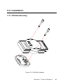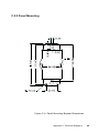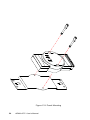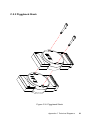
1
Ethernet to Modbus Data Gateway
User’s Manual
Preface and Table of Contents
ADAM-4572 User's Manual
Copyright Notice
This document is copyrighted, 2000, by Advantech Co., Ltd. All rights
are reserved. Advantech Co., Ltd., reserves the right to make improvements to the products described in this manual at any time without
notice.
No part of this manual may be reproduced, copied, translated or
transmitted in any form or by any means without the prior written
permission of Advantech Co., Ltd. Information provided in this manual
is intended to be accurate and reliable. However, Advantech Co., Ltd.
assumes no responsibility for its use, nor for any infringements upon
the rights of third parties which may result from its use.
Acknowledgments
ADAM is a trademark of Advantech Co., Ltd.
IBM and PC are trademarks of International Business Machines
Corporation.
CE Notification
The ADAM-4572 developed by Advantech Co., Ltd. has passed the
CE test for environmental specifications. Test conditions for passing
included the equipment being operated within an industrial enclosure,
using shielded twisted-pair RS-485 cables. In order to protect the
ADAM-4572 system from being damaged by ESD (Electrostatic
Discharge) and EMI leakage, we strongly recommend the use of CEcompliant industrial enclosure products and shielded twisted-pair RS485 cables.
Part No. 2000457200
Printed in Taiwan
1st Edition
August 2000
Preface and Table of Contents
A Message to the Customer...
Advantech Customer Services
Each and every Advantech product is built to the most exacting
specifications to ensure reliable performance in the unusual and
demanding conditions typical of industrial environments. Whether
your new Advantech equipment is destined for the laboratory or the
factory floor, you can be assured that your product will provide the
reliability and ease of operation for which the name Advantech has
come to be known.
Your satisfaction is our number one concern. Here is a guide to
Advantech’s customer services. To ensure you get the full benefit of
our services, please follow the instructions below carefully.
Technical Support
We want you to get the maximum performance from your products. So
if you run into technical difficulties, we are here to help. For most
frequently asked questions you can easily find answers in your
product documentation. These answers are normally a lot more
detailed than the ones we can give over the phone.
Please consult this manual first. If you still cannot find the answer,
gather all the information or questions that apply to your problem and,
with the product close at hand, call your dealer. Our dealers are well
trained and ready to give you the support you need to get the most
from your Advantech products. In fact, most problems reported are
minor and are able to be easily solved over the phone.
In addition, free technical support is available from Advantech
engineers every business day. We are always ready to give advice on
application requirements or specific information on the installation and
operation of any of our products.
ADAM-4572 User's Manual
Product Warranty
Advantech warrants to you, the original purchaser, that each of its
products will be free from defects in materials and workmanship for
two years from the date of purchase.
This warranty does not apply to any products which have been
repaired or altered by other than repair personnel authorized by
Advantech, or which have been subject to misuse, abuse, accident or
improper installation. Advantech assumes no liability as a consequence of such events under the terms of this Warranty.
Because of Advantech’s high quality-control standards and rigorous
testing, most of our customers never need to use our repair service. If
an Advantech product ever does prove defective, it will be repaired or
replaced at no charge during the warranty period. For out-of-warranty
repairs, you will be billed according to the cost of replacement materials, service time and freight. Please consult your dealer for more
details.
If you think you have a defective product, follow these steps:
1. Collect all the information about the problem encountered (e.g. type
of PC, CPU speed, Advantech products used, other hardware and
software used etc.). Note anything abnormal and list any on-screen
messages you get when the problem occurs.
2. Call your dealer and describe the problem. Please have your manual,
product, and any helpful information readily available.
3. If your product is diagnosed as defective, you have to request an
RMA number. When requesting an RMA (Return Material Authorization) number, please access ADVANTECH’s RMA website: http://
www.advantech.com.tw/rma. If the web sever is shut down, please
contact our office directly. You should fill in the “Problem Repair
Form”,describing in detail the application environment, configuration, and problems encountered. Note that error descriptions such as
“does not work” and “failure” are so general that we are then
required to apply our internal standard repair process.
4. Carefully pack the defective product, a completely filled-out Repair
and Replacement Order Card and a photocopy of dated proof of
purchase (such as your sales receipt) in a shippable container. A
Preface and Table of Contents
product returned without dated proof of purchase is not eligible for
warranty service.
5. Write the RMA number visibly on the outside of the package and
ship it prepaid to your dealer.
ADAM-4572 User's Manual
Contents
1. Introduction ......................................................................... 1
1.1 ADAM Data Gateway Series .............................................................. 2
1.2 Protocol .............................................................................................. 2
1.2.1
1.2.2
1.2.3
1.2.4
Overview ............................................................................................ 3
Modbus/RTU ..................................................................................... 4
Modbus/ASCII .................................................................................. 5
Modbus/TCP ..................................................................................... 6
2. Installation Guidelines ....................................................... 7
2.1 System Requirement ......................................................................... 8
2.1.1
2.1.2
Host computer ................................................................................... 8
ADAM-4572 Ethernet to Modbus Data Gateway ........................... 8
2.2 Communication Wiring .................................................................... 9
2.2.1
2.2.2
2.2.3
Serial Port Wiring ............................................................................... 9
Third Party Modbus Serial Device Wiring ...................................... 11
Ethernet Port Wiring ........................................................................ 12
2.3 Power Supply ................................................................................... 13
2.4 LED Indicator ................................................................................... 14
2.5 Network Cabling .............................................................................. 15
3. Utility Software .................................................................. 17
3.1 Installation of Utility Software ......................................................... 18
3.2 Configuration .................................................................................. 20
3.2.1
3.2.2
3.2.3
3.2.4
3.2.5
System Configuration ...................................................................... 20
Network Configuration .................................................................... 22
Serial Port Configuration .................................................................. 23
Modbus Configuration ..................................................................... 25
Status Messages ............................................................................... 26
4. Features and Specifications ............................................ 29
4.1 Features ........................................................................................... 30
4.2 Hardware Specifications .................................................................. 32
Preface and Table of Contents
Appendix A Configuration Example .................................... 35
A.1 OPC Server ..................................................................................... 36
A.2 FIX ................................................................................................... 37
Appendix B Application ........................................................ 41
Appendix C Technical Diagrams ......................................C-45
C.1 ADAM Dimensions ...................................................................... C-46
C.2 Installation ................................................................................... C-47
C.2.1 DIN-Rail Mounting ..................................................................... C-47
C.2.2 Panel Mounting ............................................................................ C-49
C.2.3 Piggyback Stack ........................................................................... C-51
Appendix D RS-485 Network ............................................... 53
D.1 Basic Network Layout ..................................................................... 55
D.2 Line Termination ............................................................................. 59
D.3 RS-485 Data Flow Control ............................................................... 61
ADAM-4572 User's Manual
Tables
Table 1-1:
Comparison of Modbus RTU and ASCII mode .......................... 5
Table 2-1:
Functional Status of LED .......................................................... 14
Table 3-1:
Table 3-2:
Settings of Modbus/ASCII ........................................................ 24
Settings of Modbus/RTU .......................................................... 24
Preface and Table of Contents
Figures
Figure 1-1: Modbus System Architecture ................................................... 4
Figure 2-1: The ADAM-4572 Module Front View .......................................... 8
Figure 2-2: Pin assignment of 3P to DB 9 cable .......................................... 9
Figure 2-3: Wiring of RS-232 Connection .................................................. 10
Figure 2-4: Wiring of RS-485 Connection .................................................. 10
Figure 2-5: Wiring of RS-422 Connection .................................................. 10
Figure 2-6: Connecting to Modbus Serial Devices (RS-232) .................... 11
Figure 2-7: Connecting to Modbus Serial Devices (RS-485) .................... 11
Figure 2-8: Connecting to Modbus Serial Devices (RS-422) .................... 12
Figure 2-9: ADAM-4572 Ethernet Interface ............................................... 12
Figure 2-10: Connecting the Hub and ADAM-4572 ...................................... 13
Figure 2-11: RJ-45 Pin Assignment (Ethernet) ........................................... 13
Figure 2-12: Position of LED Indicators ....................................................... 14
Figure 2-13: Network Cabling (Central way) ............................................... 15
Figure 2-14: Network Cabling (Distributed Architecture) ........................... 15
Figure 3-1:
Figure 3-2:
Figure 3-3:
Figure 3-4:
Figure 3-5:
Figure 3-6:
Figure 3-7:
Figure 3-8:
Figure 3-9:
Installing Configuration Utility ................................................. 18
Choosing the Destination Directory ........................................ 19
Installation Complete ............................................................... 19
Configuration Utility .................................................................. 20
System Setting Window .......................................................... 21
Network Setting Window ......................................................... 22
Port Setting Window ................................................................ 23
Modbus Configuration Window ............................................... 25
Status Bar ................................................................................. 26
Figure 4-1: ADAM-4572 Module Dimension ............................................... 33
Figure A-1:
Figure A-2:
Figure A-3:
Figure A-4:
Figure A-5:
Figure A-6:
Figure A-7:
Device Property Setting ........................................................... 36
Searching File ........................................................................... 37
Select Notepad Program ......................................................... 37
Add IP Address of ADAM-4572 to FIX ..................................... 38
Select System Configuration of FIX ........................................ 39
Select MBE Item ....................................................................... 39
Add the IP address of ADAM-4572 into MBE .......................... 40
Figure B-1: Application example of ADAM-4572 ....................................... 42
ADAM-4572 User's Manual
Figure C-1:
Figure C-2:
Figure C-3:
Figure C-4:
Figure C-5:
Figure C-6:
ADAM Modules Dimensions ................................................ C-46
DIN-Rail Adapter ................................................................... C-47
DIN-Rail Mounting ................................................................. C-48
Panel Mounting Bracket Dimensions ................................. C-49
Panel Mounting ..................................................................... C-50
Piggyback Stack .................................................................. C-51
Figure D-1:
Figure D-2:
Figure D-3:
Figure D-4:
Figure D-5:
Figure D-6:
Figure D-7:
Daisychaining ........................................................................... 55
Star structure ........................................................................... 56
Random structure .................................................................... 57
ADAM-4000 and ADAM-5000 in a network ............................. 58
Signal distortion ....................................................................... 59
Termination resistor locations ................................................ 60
RS-485 data flow control with RTS ......................................... 61
Preface and Table of Contents
ADAM-4572 User's Manual
CHAPTER
1
Introduction
1.1 ADAM Data Gateway Series
Networks have become increasingly vital for industrial automation applications. Many control devices today do not have a network port and can
only communicate with a dedicated local PC or control panel.
Advantech’s revolutionary network-enabling technology is now
allowing control devices with serial ports to connect to the Ethernet and
share networks quickly and cost-effectively. The ADAM-4572 Ethernet
to Modbus Data Gateway is a new product of ADAM Data Gateway
series from Advantech that allows users to integrate new and existing
Modbus/RTU and Modbus/ASCII serial devices to newer TCP/IP
network-based devices. Manufacturers, system integrators, and end users
can now take advantage of the ADAM-4572 to create networked
applications for remote managing and to accessing data for their control
devices that wasn't possible before.
1.2 Protocol
Originally developed for PLCs in industrial automation and manufacturing control applications, Modbus has become one of the most popular
open standard protocols in use today. When it comes to planning data
communication for open, multi-vendor industrial control systems, Modbus is the first choice of end users and integrators. Although it’s not the
most powerful protocol available, its rare simplicity allows not only rapid
implementation, but also remains flexible enough to be applied in virtually all industrial situations.
The communication mode of Modbus can be ASCII, RTU, or TCP/IP. The
ADAM-4572 is used to support applications such as protocol conversion between serial (Modbus/ASCII or Modbus/RTU) and networked
(Modbus/TCP) Modbus devices or it can be used to bridge Modbus
serial devices over TCP/IP network.
2
ADAM-4572 User's Manual
1.2.1 Overview
The Modbus/RTU and Modbus/ASCII protocols define how a “master”
device polls one or more “slave” devices to read and write real-time data
over RS-232, RS-422, or RS-485 serial data communication. The simplicity
of Modbus/RTU not only allows rapid implementation, but can also remain flexible enough to be applied in virtually all industrial situations.
During Modbus network communication, the protocol determines how
each controller will know its device address, recognize a message addressed to it, determine the kind of action to be taken, and extract any
data or other information contained in the message. If a reply is required,
the controller will construct the reply message and send it back using
Modbus protocol.
The way controllers communicate with each other is by using a masterslave technique, in which only one device (the master) can initiate queries. The other devices (the slaves) respond by supplying the requested
data to the master, or by taking the action requested in the query. Typical
master devices include host processors and programming panels. Typical slaves include programmable controllers.
It is the master that can address individual slaves and initiate a broadcast
message to all slaves. On the other hand, slaves return a response to
queries that are addressed to them individually. Responses are not returned to broadcast queries from the master.
The Modbus protocol has a definite format for the master’s query, which
incorporates the device (or broadcast) address, a function code defining
the requested action, any data to be sent, and an error-checking field.
The slave’s response message, which is also constructed using Modbus
protocol, contains fields confirming the action taken, any data to be
returned, and an error-checking field. If an error occurred in receipt of the
message, or if the slave is unable to perform the requested action, the
slave will construct an error message and send it as its response.
The basic system architecture is as follows:
Chapter 1 Introduction
3
PC
PC
PC
Ethernet
Modbus/TCP
Ethernet
ADAM
Ethernet
ADAM-4572
RS-232/485/422
ADAM
ADAM-4572
RS-232/485/422
Modbus/RTU
Modbus/ASCII
ADAM-5511
PLC
ADAM-5000/MOD
3rd party device (RTU)
Figure 1-1: Modbus System Architecture
1.2.2 Modbus/RTU
The Modbus/RTU protocol defines how a “master” device polls one or
more “slave” devices to read and write data in real-time over RS-232,
RS-422, or RS-485 serial data communication.
When using RTU mode, each 8-bit byte in a message contains two 4-bit
hexadecimal characters. The main advantage of this mode is that its greater
character density allows better data throughput than ASCII mode for the
same baud rate. Nevertheless, each message must be transmitted in continuous stream.
4
ADAM-4572 User's Manual
1.2.3 Modbus/ASCII
When using ASCII mode, each 8-bit byte in a message is sent as two
ACSII characters. The primary advantage of this ASCII mode is that it
allows time intervals of up to one second to occur between characters
without causing an error.
Mode
RTU
ASCII
Coding System
8-bit binary.
Two hexadecimal
character contained in
each ASCII character of
the message
Hexadecimal.
One hexadecimal
character contained in
each ASCII character of
the message
Bits per Byte
1 start bit,
8 data bits,
1 bit for even/odd parity;
no bit for parity
1 stop bit if parity is used;
2 bits if no parity
1 start bit ,
7 data bits,
1 bit for even/odd parity;
no bit for parity
1 stop bit if parity is used;
2 bits if no parity
Error check
CRC
LRC
Table 1-1 Comparison of Modbus RTU and ASCII mode
Chapter 1 Introduction
5
1.2.4 Modbus/TCP
As a new extension of Modbus/RTU, the Modbus/TCP protocol defines
how Modbus/RTU messages are encoded within and transported over
TCP/IP-based networks. Modbus/TCP is just as simple to implement and
flexible to apply as the original Modbus/RTU. The Modbus/TCP protocol is defined by its form of encapsulation for a Modbus request or
response. That means the Modbus request or response data is encapsulated in TCP frame that has a six-byte header in Modbus/TCP protocol.
Modbus/TCP enables the use of Modbus messaging in an Intranet running the TCP/IP protocols. Modbus/TCP is most commonly used for
Ethernet attachment of PLC’s or I/O modules to other simple field buses
or I/O networks.
6
ADAM-4572 User's Manual
CHAPTER
2
Installation
Guidelines
2.1 System Requirement
2.1.1 Host computer
1. IBM PC compatible computer with Ethernet network interface card
(Pentium CPU is strongly recommended).
2. Microsoft Windows NT 4.0 (with Service Pack 3 or above).
3. HMI software with Modbus/TCP protocol or OPC Modbus/TCP
Server (e.g. Advantech GeniDAQ 4.0; In Touch 7.0; FIX 7.0, ICONICS
5.0 or above) installed.
2.1.2 ADAM-4572 Ethernet to Modbus Data Gateway
1. One ADAM-4572 user’s manual.
2. One ADAM-4572 configuration utility diskette.
3. One ADAM-4572 module
4. One rack-mount kit
5. One 3P to DB 9 cable
(Ethernet)
Status/Power
Speed/Link
TX/RX (Ethernet)
TX/RX (Serial)
GND
(R)+Vs
TX
(RS-232)
RX
RX-
(RS-422)
RX+
TX(DATA-)
TX+
1
(DATA+)
(RS-485)
(B)GND 10
Ethernet to Modbus Data Gateway
Figure 2-1: The ADAM-4572 Module Front View
8
ADAM-4572 User's Manual
• 1
SHIELD
WHITE
• 2
Rx
RED
• 3
Tx
• 4
DTR
BLACK
• 5
GROUND
• 6
DSR
• 7
RTS
• 8
CTS
• 9
NC
TX: Transmitted Data
DTR: Data Terminal Ready
RX: Received Data
CTS: clear to Send
RTS: Request to Send
N/C:No Connection
DSR: Data Set Ready
CD: Carrier Detect
Figure 2-2: Pin assignment of 3P to DB 9 cable
2.2 Communication Wiring
2.2.1 Serial Port Wiring
We recommend that shielded-twisted-pair cables that comply with the
EIA RS-485 standard be used with the ADAM network to reduce interference. Only one set of twisted-pair cables is required to transmit both
Data and RTS signals. We advise that the following standard colors (as
indicated on the modules) be used for the communication lines:
DATA + (Y) -> Yellow
DATA - (G) -> Green
Chapter 2 Installation Guidelines
9
Wiring for RS-232 Connection
TX+
(DATA+)
TX(DATA-)
RX+
RXRX
TX
GND
+
10 ~ 30 VDC
-
+Vs
GND
Figure 2-3: Wiring of RS-232 Connection
Wiring of RS-485 Connection
Figure 2-4: Wiring of RS-485 Connection
Wiring of RS-422 Connection
Figure 2-5: Wiring of RS-422 Connection
10
ADAM-4572 User's Manual
2.2.2 Third Party Modbus Serial Device Wiring
Wiring of RS-232 connection
When connecting RS-232 interface of ADAM-4572 to a third party device with DB-9 interface for data transmission, please follow the illustration below to short pin 4 and pin 6, pin 7 and pin 8 respectively at the DB9 end.
Figure 2-6: Connecting to Modbus Serial Devices (RS-232)
Wiring of RS-485 and RS-422 connection
If you are using RS-485 or RS-422 interface for data transmission, follow
standard connection.
ADAM-4572
Modbus Serial Device
TX+
• Data +
TX-
• Data -
(DATA+)
(DATA-)
RX+
RXRX
TX
GND
+Vs
GND
TX: Transmitted Data
RX: Received Data
Figure 2-7: Connecting to Modbus Serial Devices (RS-485)
Chapter 2 Installation Guidelines
11
ADAM-4572
TX+
(DATA+)
TX(DATA-)
Modbus Serial Device
• Rx +
• Rx -
RX+
• Tx +
RX-
• Tx -
RX
TX
GND
+Vs
GND
TX: Transmitted Data
RX: Received Data
Figure 2-8: Connecting to Modbus Serial Devices (RS-422)
2.2.3 Ethernet Port Wiring
The ADAM-4572 uses a RJ-45 connector to interface with the Ethernet,
and supports 10/100 Mbps transmission speed. The ADAM-4572 configuration utility will auto-detect the current transmission speed on the
network and configure itself accordingly. Furthermore, we provide 1500
Vrms isolation for the Ethernet end to protect the ADAM-4572 from
damages caused by over-voltage.
Figure 2-9: ADAM-4572 Ethernet Interface
Grounding
The ADAM-4572 Ethernet interface, as required by the Ethernet standard, must be grounded.
12
ADAM-4572 User's Manual
Cabling requirements for the Ethernet side
Use the RJ-45 connector to connect the Ethernet port of the ADAM4572 to the Hub. The cable for connection should be Category 3 (for
10Mbps data rate) or Category 5 (for 100 Mbps data rate) UTP/STP
cable, which is compliant with EIA/TIA 586 specifications. Maximum
length between the Hub and any ADAM-4572 is up to 100 meters (ca.
300 ft).
RJ-45
1 Tx +
2 Tx 3
Rx +
4
NC
5
NC
6
Rx -
7
NC
8
NC
NC: No Connection
Figure 2-10: Connecting the Hub and ADAM-4572
Figure 2-11: RJ-45 Pin Assignment (Ethernet)
2.3 Power Supply
The ADAM-4572 is supplied with +10~+30 VDC power via twisted-pair
wire. Power consumption can also vary with connected transceivers,
phantom current, etc. Furthermore, a 34V surge protection is added to
the power end.
Chapter 2 Installation Guidelines
13
2.4 LED Indicator
The ADAM-4572 has 4 LED indicators for users to monitor its functional
status.
Figure 2-12: Position of LED Indicators
☛ Note: LED indicators will be red or green, not both
LED
Color
Red
Status/Power
Green
Red
Speed/Link
Green
Red
Tx/Rx (Ethernet)
Green
Red
Tx/Rx (Serial)
Green
Status
Description
ON
Heartbeat (1 time/sec)
OFF
Not working
ON
Power ON
OFF
Power OFF
ON
100 Mbps speed
OFF
10 Mbps speed
ON
Valid network link
OFF
Invalid network link
ON
Data being transmitted
OFF
No data being transmitted
ON
Data being received
OFF
No data being received
ON
Data being transmitted
OFF
No data being transmitted
ON
Data being received
OFF
No data being received
Table 2-1 Functional Status of LED
14
ADAM-4572 User's Manual
2.5 Network Cabling
The following illustration is a quick reference of network cabling for you
to set up network in your factory.
Figure 2-13: Network Cabling (Central way)
Figure 2-14: Network Cabling (Distributed Architecture)
Chapter 2 Installation Guidelines
15
16
ADAM-4572 User's Manual
CHAPTER
3
Utility Software
3.1 Installation of Utility Software
Before you use the ADAM-4572, you have to install the ADAM-4572
configuration utility. Please follow the steps as described below:
1. Insert the ADAM-4572 configuration utility diskette into the floppy
drive (e.g. a:\) on the host PC. Change the host computer’s default
drive from C: to A:
2. Use your Windows Explorer or the Windows Run command to execute
the Setup Program. (The path for the Setup program on diskette should
be A:\setup.exe, if your default floppy drive is A:).
Figure 3-1: Installing Configuration Utility
3. The Setup program will specify for you a default installation path,
C:\Program Files\Advantech\ADAM4572. If you are not satisfied with
the default installation path, just click the Browse button to change to
another path. After you have specified the installation path, click the
Next button. The program will start to copy the program files to your
computer.
18
ADAM-4572 User's Manual
Figure 3-2: Choosing the Destination Directory
Figure 3-3: Installation Complete
4. After Setup has copied all program files to your computer, click the
Finish button to finish the installation. Configuration utility will then
search the ADAM-4572 device on your local area network automatically.
Chapter 3 Utility Software
19
Figure 3-4: Configuration Utility
3.2 Configuration
The ADAM-4572 provides easy configuration by Windows utility
through Ethernet connection. This Windows utility searches all the
ADAM-4572 devices on the network automatically and you can configure various parameters for TCP/IP configuration easily. For secure administration, it can also restrict the access right for configuration to only
one host PC to enhance network security. With this secure function
enabled, other PCs will not have access right for configuration. The
Windows utility consists of four functional categories: System, Network,
Port and Modbus, which are presented on the toolbar of the configuration utility.
3.2.1 System Configuration
Configuration utility can only search the ADAM-4572 devices on the
local network segment and cannot search beyond a router or gateway.
Therefore, before you set up the network, you have to make sure that all
the ADAM-4572 devices that you want to monitor must reside on the
same local network segment with the host PC.
20
ADAM-4572 User's Manual
Figure 3-5: System Setting Window
ADAM Data Gateway
In this column, you will see all the found ADAM-4572 devices are listed
when you use the configuration utility to auto-search ADAM-4572 devices. The specific number following each ADAM-4572 device is its
Ethernet Address. The Ethernet Address is what helps the local system
to identify and locate each ADAM device. This Ethernet Address is
already set before delivery from factory, hence no need for further configuration.
Device Name
Configuration utility offers you device name information to distinguish a
specific ADAM-4572 from other ADAM-4572. Names longer than 128
characters cannot be used. It is best to choose a name you can remember.
Device Description
This field is to record the function and purpose and other information for
each ADAM-4572 device in more detail for easy management and maintenance. You are allowed to describe in your own words.
Firmware Version
In this field, configuration utility represents the firmware version of the
ADAM-4572. Sometimes you might need to refer to the firmware version
to determine functions available on the ADAM-4572 device. In case of
any problem that might concern the firmware version, please provide the
firmware version number to our Customer Service.
Chapter 3 Utility Software
21
3.2.2 Network Configuration
Figure 3-6: Network Setting Window
MAC Address
This is also called Ethernet address and needs no further configuration.
Link Speed
This function will show the current linking speed to be either 10Mbps or
100Mbps. However, the utility will auto-detect the current transmission
speed on the network segment and set the transmission speed for the
device accordingly without your further efforts.
Duplex Mode
The utility will detect the current transmission mode (half-duplex or fullduplex) on the network segment, and set the transmission mode for the
device accordingly without your further efforts.
IP address, Subnet Mask, Default Gateway
The IP address identifies your ADAM-4572 device on the global network. Each ADAM-4572 has same default IP address 10.0.0.1. You have
to ask your network administrator to obtain a specific IP address and
then configure each ADAM-4572 with the individual IP address.
22
ADAM-4572 User's Manual
3.2.3 Serial Port Configuration
Figure 3-7: Port Setting Window
Name
To specify which port on the ADAM-4572 is to be connected to the
Modbus serial device. Since the ADAM-4572 has only one serial port,
the only available port name is Port 1.
Description
You can give more detailed description of the function of the port for
easy management and maintenance. Descriptions longer than 128 characters cannot be used.
Type
Each ADAM-4572 offers 3 kinds of serial interfaces, RS-232, RS-485 and
RS-422. You can use any one of the 3 serial interfaces according to your
requirements. You must also pay special attention to the wiring scheme
of the ADAM-4572 serial connection to make sure it conforms to the
serial type you select.
☛ Note: Special Function on Serial Port Handling
RS-485 - The biggest advantage of the ADAM-4572 serial port handling
is when you configure the ADAM-4572 serial port to RS-485 and all
Chapter 3 Utility Software
23
3kinds of serial interfaces can be connected to ADAM-4572. Every Modbus device connected to any of the 3 serial buses must have a unique
Modbus ID, and can be accessed from host PC through ADAM-4572.
RS-422 - When configuring the ADAM-4572 serial port to RS-422, RS422 and RS-232 type of serial interfaces can be connected to ADAM4572. All devices connected to these 2 serial buses can be accessed from
host PC through ADAM-4572.
RS-232 - When configuring the ADAM-4572 serial port to RS-232, only
the RS-232 type of serial interface can be connected to ADAM-4572.
Parity, Data bits, Stop bits
The settings for these parameters depend on the protocol that is running
on the connected Modbus device (i.e. Modbus/ASCII or Modbus/RTU).
Parity
Option
None
Even or Odd
Data Bits
7
7
Stop Bits
2
1
Modbus/ASCII
Table 3-1 Settings of Modbus/ASCII
Parity
Option
None
Even or Odd
Data Bits
8
8
Stop Bits
2
1
Modbus/RTU
Table 3-2 Settings of Modbus/RTU
Baud Rate
While setting the baud rate, please note that the value should conform to
the current transmission speeds of connected devices.
24
ADAM-4572 User's Manual
3.2.4 Modbus Configuration
Figure 3-8: Modbus Configuration Window
Lock the Configuration of Host
This option is enabled in order to protect all configuration settings from
being changed inadvertently. When this option is enabled, only the PC
with specified IP address (e.g. 172.20.20.2) is allowed to set the configuration whereas other PCs will not be given the access right for configuration and the option will be grayed out accordingly.
Modbus/TCP port number
The default port number of Modbus/TCP is 502. If you want to select the
port yourself, you can set it within the range of 512 to 50000. Note that a
port number below 512 is already reserved in each situation for other
specific uses and thus unavailable for your selection.
Modbus Serial Frame Timeout
RTU Frame Timeout
This option specifies the time duration in milliseconds for the ADAM4572 to wait for a response after it has issued a command while using
Modbus/RTU. After the timeout is expired and no response is received,
the ADAM-4572 will regard the command as failed. Note that the Timeout for the host PC must be greater than the timeout setting here specified, otherwise an error will occur.
Chapter 3 Utility Software
25
ASCII Frame Inter Char. Timeout
This option specifies the time interval in milliseconds between characters within the Modbus/ASCII message. If a greater interval occurs, the
receiving device assumes an error has occurred.
Modbus Serial Frame Type
This option specifies whether to Retain the original encapsulated frame
type or to Convert to Modbus/ASCII frame anyway.
When finished the configuration of the settings, please follow the steps
to make these settings effective on the ADAM-4572.
—>
Click “OK”
—>
Click “Apply”
—> Complete
Click “Reset”
3.2.5 Status Messages
The status message shown at the bottom of the utility window reflects
the current status of ADAM-4572.
Figure 3-9: Status Bar
26
ADAM-4572 User's Manual
Ready
The configuration utility has found the ADAM-4572 and it is ready for
use.
Searching ADAM-4572
The configuration utility is searching the ADAM-4572.
Querying DATA from ADAM-4572
The configuration utility is getting data from the ADAM-4572.
Device Ready
The ADAM-4572 is ready to be configured and is now waiting for acknowledgement from the device.
Lost Connection from the Device
Due to device shut down or network failure, the configuration utility has
lost connection after 5 seconds.
Fail to apply this setting to the device
Specific settings are not accepted by ADAM-4572.
The device fails to respond
The connected device does not respond.
Fail to reset the device
Fail to reset the ADAM-4572.
Chapter 3 Utility Software
27
28
ADAM-4572 User's Manual
CHAPTER
4
Features and
Specifications
The ADAM-4572 is designed to be a Modbus data gateway, which serves
as an interface between Modbus serial devices and computer hosts running Modbus/TCP on Ethernet. Fully compliant with Modbus/TCP, it is
ideal for customers who are looking for an easy way to connect their
existing devices or controllers running Modbus serial protocols (Modbus/ASCII or Modbus/ RTU) to Ethernet network. It functions as a bridge
between Modbus serial devices or controllers over TCP/IP Ethernet.
Benefits are also abundant for customers who want to expand their Ethernet-based Modbus (Modbus/TCP) application.
The ADAM-4572 is both cost-effective and convenient in connecting
your existing Modbus devices to Ethernet running Modbus/TCP without extra costs in network re-investment. With support for RS-232/422/
485 modes, users can very conveniently connect their various Modbus
devices to TCP/IP over Ethernet network. Host and HMI performances
can also be enhanced with load-sharing benefits.
4.1 Features
The major features of ADAM-4572 are described as below:
Compact design without any hardware configuration
The ADAM-4572 can be readily connected to or removed from the network without shutting down the system. The configuration utility will
search the ADAM-4572 devices on the network every 10 seconds. Also,
when you are performing system maintenance, you can remotely connect to the ADAM-4572 and acquire on-site data.
Allow up to 8 clients for data accessing simultaneously
Any client running Modbus/TCP on Ethernet can access data of Modbus serial devices through ADAM-4572. Up to 8 clients are allowed
simultaneously to connect to ADAM-4572 and access Modbus serial
data through ADAM-4572.
30
ADAM-4572 User's Manual
Support popular HMI software with Modbus/TCP driver or OPC server
ADAM-4572 is designed to be fully compatible with most popular HMI
software, which supports Modbus/TCP protocol with Modbus/TCP driver or OPC server (e.g. Advantech GeniDAQ 4.0, In Touch 7.0, FIX 7.0,
ICONICS 5.0 and above).
Free limitation of OS platform
Any PC host running Modbus/TCP protocol, no matter what OS platform it is running on, can connect to and access data through ADAM4572.
Independent wiring and flexible handling on serial interfaces
ADAM-4572 provides an individual wiring terminal for connecting 3
different serial interfaces, RS-232, RS-485, and RS-422 independently.
The flexible and cost effective design of ADAM-4572 expands the serial
connection without physically expanding serial interface from 1 port to 2
or 3 ports. While configuring serial port of ADAM-4572 to be RS-485, it
allows the host PC to access RS-232, RS-485, and RS-422 Modbus serial
devices through ADAM-4572. While configuring ADAM-4572 serial port
to be RS-422, it allows the host PC to access RS-232 and RS-422 Modbus
serial devices through ADAM-4572.
Auto-searching Windows utility
The configuration utility can search all the ADAM-4572 devices on the
network automatically and configure them according to the current network status, saving your effort to acquire the status information yourself. Meanwhile, the utility can optionally restrict the access for configuration to only one PC, allowing no other PCs to perform configuration.
This is often done to enhance network security and reduce system malfunctions due to unauthorized changes made to the system.
Real-time Operation System (RTOS)
The ADAM-4572 adopts pSOS, a Real Time Operating System (RTOS),
as its software platform. The pSOS System has long been recognized as
an excellent platform, which offers robust stability and quality for overall
performance on the ADAM-4572.
Chapter 4 Features and Specifications
31
Surge protection for RS-485 line and power supply
The ADAM-4572 provides surge protection for the power input and
some vital part of the internal circuitry. For the power input, the surge
protection is up to 34V, and when the instantaneous power output rises
up to 200 Watts, the circuit will break to protect the device from being
damaged. For RS-485/422, the surge protection is up to 18V, and when
the instantaneous power output rises up to 200 Watts, the circuit will
break to protect the device from damages.
4.2 Hardware Specifications
• Protocol: TCP, UDP, IP, ARP
Modbus: Modbus/RTU, Modbus/ASCII, Modbus/TCP
• Network Port: 10 BASE-T IEEE 802.3, 100 BASE-TX IEEE 802.3u
RJ-45 connector
• Serial Port: RS-232/485/422
IO plug-in connector (20-pin terminal)
Transmission speed: 300 bps to 115.2 kbps
Format: parity: odd, even, none
Data bit: 7, 8
Stop bit: 1, 2
• Compatibility: Ethernet: version 2.0/IEEE 802.3, IEEE 802.3u
Modbus/Serial: Modbus/ASCII, Modbus/RTU
Network: Modbus/TCP
• Diagnostic LEDs: Network: Tx/Rx, Link, Speed (10/100Mbps), Power
Serial: Tx/Rx, Status
• Utility Software: Windows-based, device auto-searching
Device Setting: name, description, serial port
• Compatible with application software running on Modbus/TCP
standard
• Power Requirements: unregulated 10 to 30 VDC with protection from
power surge
32
ADAM-4572 User's Manual
• Power Consumption: 3 watts
• Case: ABS with captive mounting hardware
• Accessories: Nylon DIN-rail mounting adapter SECC panel mounting
bracket
• Operating Temperature: 0 to 60° C
• Storage Temperature: -20 to 80° C
• Operating Humidity: 20 to 95% (non-condensing)
• Storage Humidity: 0 to 95% (non-condensing)
• Dimension
Figure 4-1: ADAM-4572 Module Dimension
• Weight: Total Weight (only ADAM-4572) = 150 g
Chapter 4 Features and Specifications
33
34
ADAM-4572 User's Manual
Appendix
A
Configuration
Example
A.1 OPC Server
When you want to use the OPC Server with Modbus/TCP protocol,
please refer to the following. Since OPC servers from different vendors
could vary, we will use the Advantech Modbus/TCP OPC Sever as an
example. For further details, please refer to each manual.
Device Setting
Enter the proper settings for your ADAM-4572 device.
Figure A-1: Device Property Setting
IP Address
You should enter the proper IP address for the ADAM-4572; otherwise it
will not be located on the network.
TCP Port
This is the TCP port on the ADAM-4572 you want to connect to (default
502). You should enter the proper TCP port for the ADAM-4572; otherwise it is not to be found on the network.
36
ADAM-4572 User's Manual
A.2 FIX
When you are using Intellution FIX 6.X or above, which is a specific
HMI software, and get connected to the ADAM-4572, please follow the
steps below to carry on with its configuration:
1. Access the Hosts file on your system disk. The path is
C:\WINNT\system32\drivers\etc\Hosts. Or you can use Windows Find
to locate the Hosts file more quickly.
Figure A-2: Searching File
2. Double-click the Hosts file. Since there is no program association for
this file type, an Open With dialog box will appear. Select NOTEPAD
program to open the Hosts file.
Figure A-3: Select Notepad Program
Appendix A Configuration Example
37
3. Add the IP address of ADAM-4572 into your Hosts file. For your
proper IP address, please ensure that it is identical with that which is
found on your configuration utility.
Figure A-4: Add IP Address of ADAM-4572 to FIX
38
ADAM-4572 User's Manual
4. Access Start menu/Intellution FIX/System Configuration.
Figure A-5: Select System Configuration of FIX
5. Select MBE Item
Figure A-6: Select MBE Item
Appendix A Configuration Example
39
6. Add the IP address of ADAM-4572 into MBE item
Figure A-7: Add the IP address of ADAM-4572 into MBE
7. Execution
When you finish all the settings, it is now ready to run your HMI
software.
40
ADAM-4572 User's Manual
Appendix
B
Application
The followings are the application examples for the ADAM-4572.
ERP, MES, Plant Historian,
Third-party Application/System
Remote Stations
GeniDAQ
Operator Stations
-NT/95/98
ADAM Utility
Engineer Stations
-Windows NT
Internet or Modem
Access Link
TCP/IP Network
(Ethernet)
Eth ern et
Eth ern et
ADAM
4572
ADAM
4572
...Plug-and-Play
(Ethernet Auto Detection)
Remote I/O
ADAM 5511
Standalone Controller
ADAM 5000/MOD
DA&C Modules
ADAM 4000
DA&C I/O
Other 3rd Party Modbus Controllers
Figure B-1: Application example of ADAM-4572
Modbus is the most popular industrial network in the world, yet solutions for integration with the Ethernet are limited. Even connecting via
Com Port, it also increases loading of PC and frequently leads to low
performance. The ADAM-4572 provides a perfect solution to integrate
Modbus into Ethernet to serve as a high-performance and cost-effective
network.
In various industry domains, such as Water Treatment, Power Generation, Automotive, Semiconductor, Building Automation, Telecom System, and so on. Thousands of system projects can be completed with
ease for many specific applications.
For example, in the application for water treatment site, the field equipments came to be distributed in such a vast area, which aggravates the
difficulty to monitor and control the status of each DA&C equipment.
Most of these industrial equipments are connected to Modbus network,
including the ADAM-5511, ADAM-5000/MOD, and third-party controllers. The ADAM-4572 works as a communication bridge between Modbus and Ethernet, integrating field instruments with Human Machine
Interface as a complete SCADA. Plug-and-Play function makes this
42
ADAM-4572 User's Manual
architecture much more flexible, engineer can use configuration utility to
add or remove the ADAM-4572 for the network at anytime. It provides
not only configuration function, but also monitoring and auto-detecting
function of the ADAM-4572 status. In addition, if there is any problem
occurring on job site, engineers can also maintain this system via Internet or modem thousands of miles away.
Appendix B Application
43
44
ADAM-4572 User's Manual
Appendix
C
Technical
Diagrams
C.1 ADAM Dimensions
Figure C-1: ADAM Modules Dimensions
46
ADAM-4572 User's Manual
C.2 Installation
C.2.1 DIN-Rail Mounting
Figure C-2: DIN-Rail Adapter
Appendix C Technical Diagrams
47
Figure C-3: DIN-Rail Mounting
48
ADAM-4572 User's Manual
C.2.2 Panel Mounting
Figure C-4: Panel Mounting Bracket Dimensions
Appendix C Technical Diagrams
49
Figure C-5: Panel Mounting
50
ADAM-4572 User's Manual
C.2.3 Piggyback Stack
Figure C-6: Piggyback Stack
Appendix C Technical Diagrams
51
52
ADAM-4572 User's Manual
Appendix
D
RS-485 Network
Appendix D RS-485 Network
53
EIA RS-485 is the industry’s most widely used bidirectional, balanced
transmission line standard. It is specifically developed for industrial multidrop systems that should be able to transmit and receive data at high
rates or over long distances.
The specifications of the EIA RS-485 protocol are as follows:
• Maximum line length per segment: 1200 meters (4000 feet)
• Throughput of 10 Mbaud and beyond -Differential transmission (balanced lines) with high resistance against noise
• Maximum 32 nodes per segment
• Bi-directional master-slave communication over a single set of twisted-pair cables
• Parallel connected nodes, true multi-drop
ADAM-5000 systems are fully isolated and use just a single set of twisted pair wires to send and receive! Since the nodes are connected in
parallel they can be freely disconnected from the host without affecting
the functioning of the remaining nodes. An industry standard, shielded
twisted pair is preferable because of the high noise ratio of the environment.
When nodes communicate through the network, no sending conflicts
can occur since a simple command/response sequence is used. There is
always one initiator (with no address) and many slaves (with addresses).
In this case, the master is a personal computer that is connected with its
serial, RS-232, port to an ADAM RS-232/RS-485 converter. The slaves
are the ADAM-5000 systems. When systems are not transmitting data,
they are in listen mode. The host computer initiates a command/response
sequence with one of the systems. Commands normally contain the address of the module the host wants to communicate with. The system
with the matching address carries out the command and sends its response to the host.
54
ADAM-4572 User's Manual
D.1 Basic Network Layout
Multi-drop RS-485 implies that there are two main wires in a segment.
The connected systems tap from these two lines with so called drop
cables. Thus all connections are parallel and connecting or disconnecting of a node doesn’t affect the network as a whole. Since ADAM-5000
systems use the RS-485 standard and an ASCII-based commands set,
they can connect and communicate with all ASCII-based computers and
terminals. The basic layouts that can be used for an RS-485 network are:
Daisychain
The last module of a segment is a repeater. It is directly connected to the
main-wires thereby ending the first segment and starting the next segment. Up to 32 addressable systems can be daisychained . This limitation
is a physical one. When using more systems per segment the IC driver
current rapidly decreases, causing communication errors. In total, the
network can hold up to 256 addressable systems. The limitation on this
number is the two-character hexadecimal address code that can address
256 combinations. The ADAM converter, ADAM repeaters and the host
computer are non addressable units and therefore are not included in
these numbers.
Setgment 1
Coverter
RS232/RS485
Setgment 2
Repeater
1
RS-485
RS-232
1
2
N
1
Figure D-1: Daisychaining
Appendix D RS-485 Network
55
Star Layout
In this scheme the repeaters are connected to drop-down cables from the
main wires of the first segment. A tree structure is the result. This
scheme is not recommended when using long lines since it will cause a
serious amount of signal distortion due to signal reflections in several
line-endings.
Figure D-2: Star structure
56
ADAM-4572 User's Manual
Random
This is a combination of daisychain and hierarchical structure.
Figure D-3: Random structure
Appendix D RS-485 Network
57
Combination of an ADAM-4000 and an ADAM-5000 in a
RS-485 Network
The following figure shows how to integrate ADAM-4000 and ADAM5000 systems in a network.
Coverter
RS232/RS485
Repeater
RS-485
2
RS-232
repeater
1
1
ADAM-5000
SYSTEM
2
3
ADAM-4000 I/O
MODULES
Figure D-4: ADAM-4000 and ADAM-5000 in a network
☛ Note:The speed of ADAM-4000 and ADAM-5000 in a RS-485
network should be the same.
58
ADAM-4572 User's Manual
D.2 Line Termination
Each discontinuity in impedance causes reflections and distortion. When
a impedance discontinuity occurs in the transmission line the immediate
effect is signal reflection. This will lead to signal distortion. Specially at
line ends this mismatch causes problems. To eliminate this discontinuity,
terminate the line with a resistor.
Figure D-5: Signal distortion
The value of the resistor should be a close as possible to the characteristic impedance of the line. Although receiver devices add some resistance to the whole of the transmission line, normally it is sufficient to the
resistor impedance should equal the characteristic impedance of the line.
Example:
Each input of the receivers has a nominal input impedance of 18 kΩ
feeding into a diode transistor- resistor biasing network that is equivalent to an 18 kΩ input resistor tied to a common mode voltage of 2.4 V. It
is this configuration which provides the large common range of the receiver required for RS-485 systems! (See Figure C-6 below).
Appendix D RS-485 Network
59
Figure D-6: Termination resistor locations
Because each input is biased to 2.4 V, the nominal common mode voltage
of balanced RS-485 systems, the 18 kΩ on the input can be taken as
being in series across the input of each individual receiver.
If thirty of these receivers are put closely together at the end of the
transmission line, they will tend to react as thirty 36kΩ resistors in parallel with the termination resistor. The overall effective resistance will need
to be close to the characteristics of the line. The effective parallel receiver resistance RP will therefore be equal to:
RP = 36 x 103/30 = 1200 Ω
While the termination receptor RT will equal:
RT = RO / [1 - RO/RP]
Thus for a line with a characteristic impedance of 100 Ω resistor
RT = 100/[1 - 100/1200] = 110 Ω
60
ADAM-4572 User's Manual
Since this value lies within 10% of the line characteristic impedance.
Thus as already stated above the line termination resistor RT will normally equal the characteristic impedance Zo.
The star connection causes a multitude of these discontinuities since
there are several transmission lines and is therefore not recommend.
☛ Note: The recommend method wiring method, that causes a minimum amount of reflection, is daisy chaining where all receivers tapped from one transmission line needs only to
be terminated twice.
D.3 RS-485 Data Flow Control
The RS-485 standard uses a single pair of wires to send and receive data.
This line sharing requires some method to control the direction of the
data flow. RTS (Request To Send) and CTS (Clear To Send) are the most
commonly used methods.
Figure D-7: RS-485 data flow control with RTS
Appendix D RS-485 Network
61
Intelligent RS-485 Control
ADAM-4510 and ADAM-4520 are both equipped with an I/O circuit
which can automatically sense the direction of the data flow. No handshaking with the host (like RTS, Request to Send) is necessary to receive
data and forward it in the correct direction. You can use any software
written for half-duplex RS-232 with an ADAM network without modification. The RS-485 control is completely transparent to the user.
62
ADAM-4572 User's Manual