1
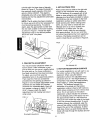
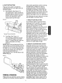
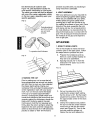
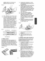
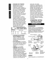
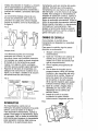
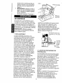
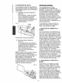
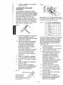
___/'j-__
Operator's Manual
CRRFTSMRNo
Heavy Duty
PLATE JOINER
Model No.
900.277300
CAUTION:
Read and follow all
Safety Rules and Operating
Instructions before First Use
of this Product.
Sears, Roebuck and Co., Hoffman Estates, IL 60179 USA
Form No. 381555-00
MAY96-CD-2
Printed
in U.S.A.
Full one year warranty on Craftsman Industrial
Plate Joiner
If this Craftsman Industrial Plate Joiner fails due to a defect in material or workmanship
within one year from the date of purchase Sears will repair it free of charge.
WARRANTY SERVICE IS AVAILABLE BY SIMPLY RETURNING THE TOOL TO THE
NEAREST STORE OR SERVICE CENTER IN THE UNITED STATES.
This warranty gives you specific legal rights and you may have other rights which vary
from state to state.
Sears,
Roebuck
and Co., Hoffman
IMPORTANT SAFETY
INSTRUCTIONS
READ
injury, including
•
ALL INSTRUCTIONS
insulation
•
AREA
or wet locations.
Prevent
grounded
pipes,
•
of flammable
liquids or gases.
GUARD AGAINST
SHOCK.
does not take the
damaged
invite injuries.
CONSIDER
WORK
tool in presence
•
ELECTRIC
body contact
surfaces.
radiators,
ranges,
DON'T
FORCE
be kept
When
be stored
and high or locked-up
reach of children.
•
and
should
away from work area.
STORE IDLE TOOLS.
use, tools should
cords.
with
For example;
refrigerator
enclosures.
KEEP CHILDREN
AWAY. Do not
let visitors contact tool or extension
cord. All visitors
SERVICING
USE
REPLACEMENT
or replace
CLEAN.
Keep work area well lit. Do not use
place of normal safety precautions
when
operating this tool. The insulation system
is for added protection against injury
resulting from a possible electrical
insulation failure within the tool.
Repair
AREA
areas and benches
tools in damp
thickness of insulation between you and
the tool's electrical system. Tools built with
this insulation system are not intended to
be grounded. As a result, your tool is
equipped with a two prong plug which
permits you to use extension cords
without concern for maintaining
a
ground connection.
PARTS.
WORK
ENVIRONMENT.
Don't expose
power tools to rain. Don't use power
Double insulated tools are constructed
throughout
with two separate layers of
electrical insulation or one double
CAUTION:
WHEN
ONLY IDENTICAL
KEEP
Cluttered
DOUBLEINSULATION
Double
Do
SAFETY INSTRUCTIONS
FOR ALL TOOLS
•
NOTE:
IL 60179
electrician to install the proper outlet.
not change the plug in any way.
WARNING:
When using electric tools,
basic safety precautions should always be
followed to reduce risk of fire, electric
shock, and personal
the following:
Estates,
not in
in dry,
place - out of
TOOL.
It will do the
job better and safer at the rate for
which it was intended.
POLARIZEDPLUGS
•
Polarized plugs (one blade is wider than
the other) are used on equipment
to
reduce the risk of electric shock. When
USE RIGHT TOOL.
Don't force
small tool or attachment
to do the
job of a heavy-duty
tool. Don't use
tool for purpose not intended.
provided, this plug will fit into a polarized
outlet only one way. If the plug does not fit
fully into the outlet, reverse the plug. If it
still does not fit, contact a qualified
°
DRESS
PROPERLY.
loose clothing
2
Do not wear
or jewelry.
They can
•
be caughtin movingparts. Rubber
gloves and non-skidfootwearare
recommendedwhen working
outdoors.Wear protectivehair
coveringto containlong hair.
voltage
USE SAFETY
doubt, use the next heavier gage.
The smaller the gage number, the
heavier the cord.
GLASSES.
Also
DON'T ABUSE CORD. Never carry
tool by cord or yank it to disconnect
from receptacle.
•
CORDS.
WITH
CARE.
16
16
16
12
USE EXTENSION
When
tool is used
STAY ALERT. Watch what you are
doing. Use common sense. Do not
and if
damaged,
have repaired by
authorized service facility. Inspect
operate
extension cords periodically
Before further
CHECK
and
tool when you are tired.
DAMAGED
PARTS.
use of the tool, a
guard or other part that is damaged
replace if damaged.
Keep handles
dry, clean, and free from oil
should be carefully checked to
determine that it will operate
and grease.
OFF
properly
and perform
when not in use, before
function.
Check
DISCONNECT
TOOLS
16
14
14
12
14
12
NotRecommended
outdoors, use only extension cords
intended for use outdoors and
so marked.
and clean for
toot cords periodically
OR LOCK
its intended
for alignment
of
servicing, and when changing
accessories,
such as blades,
bits, cutters.
moving parts, binding of moving
parts, breakage of parts, mounting,
REMOVE ADJUSTING
KEYS AND
WRENCHES.
Form habit of
affect its operation. A guard or other
part that is damaged should be
checking
adjusting
properly repaired or replaced by an
authorized service center unless
and any other conditions
to see that keys and
wrenches are removed
from tool before turning
AVOID UNINTENTIONAL
otherwise
it on.
off when plugging in.
EXTENSION
CORDS.
your extension
condition.
When
indicated
this instruction
use tool if switch
and off.
Make sure
that may
elsewhere
manual.
defective switches
authorized service
STARTING.
Don't carry tool with
finger on switch. Be sure switch is
•
18
18
16
14
MAINTAIN
Follow instructions for lubricating
and changing accessories. Inspect
•
AWG
OUTDOOR
TOOLS
rating.
Total Lengthof Cord in Feet
0-25
26-50
51-100 I01-150
0-50
51-100 101-200 201-300
0 - 6
610
10 - 12
12 -16
better and safer performance.
•
If in
DON'T OVERREACH.
Keep proper
footing and balance at all times.
Keep tools sharp
•
and
ampere
Ampere Rating
More Not more
Than Than
Use clamps or a
It's safer than
using your hand and it frees both
hands to operate tool.
•
on cord length
nameplate
Minimum Gage for Cord Sets
Keep cord from
SECURE WORK.
vise to hold work.
depending
Volts
120V
240V
heat, oil, and sharp edges.
•
in loss of power
and overheating.
The following
table shows the correct size to use
use face or dust mask if operation
is dusty.
•
resulting
replaced by
center. Do not
does not turn it on
SAVE THESE
cord is in good
using an extension
INSTRUCTIONS
cord, be sure to use one heavy
enough to carry the current your
product will draw. An undersized
cord will cause a drop in line
3
in
Have
The various adjustments
on the patented
base/fence
assembly will enable you to
make virtually any biscuit joint imaginable
The tool may be further enhanced by
some simple jigs and fixtures that can be
easily made. Some of the more common
biscuit joinery applications
are shown in
Figure 3 and are discussed in detail in the
applications
section of this manual.
INTRODUCTION
Examine Figure 1 and your plate joiner for
a few minutes to become familiar with the
various features and the names used to
discuss the various controls and you will
need to know where they are.
FIG 3
FIG 1
_
describe
Lock
thefn. knob
The following
sections
EDGE TO EDGE JOINT
will
EDGE
I
,,,./.4
M_TaEL-------b.X I
Paddie switch
JOINT -----]
L__J
Dust
exhaust
po_
Lock on bu_on
Height
adjustment
knob
45 ° FRAME
Adjustable
JOINT
JOINT
_
[-
OFFSE
OFFSET JOINT
SWITCH
Your plate joiner has a paddle switch
located on the underside, as shown in
fence.
_f_
Anti-slippage pin
\
Lock knob
\ Plunge depth
adjustment
knob
OVERVIEW
Figure 1. To turn the tool on, depress the
paddle switch. To turn the tool off, release
the paddle switch. To lock the tool on for
continuous operation, there is a lock on
button located at the rear of the tool just
above the cord. When cutting always hold
the tool with one hand on the paddle
switch and one hand on the handle. To
lock the tool on, depress and hold the
paddle switch as you depress the lock
button. Hold the lock button in as you
gently release the paddle switch. The tool
will continue to run. To turn the tool off
You have purchased
a precision
woodworking
tool. The function of the
plate joiner is to enable you to make
extremely strong and accurate joints in
wood and wood byproducts.
from a locked on condition, depress
release the paddle switch once.
The tool works by a plunging action to
precisely cut crescent shaped slots for the
placement of flat wooden dowels or
"biscuits" like those shown in Figure 2.
and
BLADEREPLACEMENT
In time your saw blade will wear out and
need replacement.
FIG 2
1/2"
To remove the blade, follow the
steps below.
5/16"
2-3/8" I
:
! 2-3/16"_
1.
2.
1-13/1_
Turn off and unplug the plate joiner.
Remove the 4 torx head screws
from the bottom of the shoe, using
the T20 torx screwdriver
provided.
(60m__
(56rnm)__
(46rnm)[
I
#20
_
3.
4.
I
#10
#0
(flat biscuits)
4
Rotate the shoe out of the way.
Use the spanner wrench provided
to loosen (counterclockwise)
the
blade nut. Depress the spindle lock
pin on the top of the gear case to
hold the spindle while you unscrew
the nut.
.
Remove
(See Applications
section
Joints, Figure 27.)
The height adjustment
is accomplished
by
first loosening the lock knob on the right
side of the fence and then rotating the
the blade and have it
sharpened or replace it with a
new one. (Available through Sears
service centers.
.
under Miter
FIG 5
Adjustment Knob
Reinstall the blade by reversing the
steps above. Be sure blade teeth
point counterclockwise
as shown in
Figure 4.
FIG 4
Lock knob
knurled adjustment
knob until the desired
height is reached (see Figure 5).
.
Tightening
the lock knob will then
automatically
align the fence parallel to the
blade and lock it in position. The vertical
scale and pointer located directly under
the lock knob can be used to assist in
IMPORTANT:
Always check the fine
depth adjustment
when sharpening
or replacing the blade. Adjust if
necessary.
(See "Controls" section).
setting this height. The scale readings
indicate distance from the blade centerline
to the fence surface when the fence is set
at 90 ° (see Figure 6). If the depth scale
ever needs to be adjusted, loosen the two
screws that secure the scale and move
THE CONTROLS
The heart of your plate joiner is the
base/fence
assembly. All of the controls
that let you make a variety of precision
cuts are located on this assembly. Take a
few minutes to become familiar with the
various controls.
FIG 6
Pointer points
to 1/2" mark
CAUTION:
Always turn off and unplug
plate joiner before making any adjustments.
1. ADJUSTABLE
Centerline of
FENCE
The adjustable fence provides a sturdy,
precise reference surface to determine the
point at which the slots for the biscuits will
be cut. Its adjustable height feature allows
you to position biscuit slots as close as
3/16" (4.76mm) and as distant as 1-3/8"
(35mm) measured from the workpiece
surface to the centerline of the blade (see
Figure 6). The adjustable
angle feature
allows a full range of settings from 0 ° to 90
as well as a reverse 45 ° bevel which
allows
outside
registration
_
the scale until the pointer is indicating
proper reading (see Figure 6).
2. PLUNGE
DEPTH
blade
the
ADJUSTMENT
The depth of cut can be set to match the
dimensions
of the particular size biscuit
you will be using. The numbers on the
depth adjustment
knob (0,10,20,M)
on miter joints.
5
coincidewith the three sizes of biscuits
shownin Figure2. The letter M stands for
the maximumdepthcapacityof the tool
which is 20mm (25/32").This depthis
obtainableonly with a new bladeand by
backingout the fine adjustmentscrew (see
next section).
NOTE:The M setting has been provided
for future use and will not be necessaryfor
most biscuitingoperations.To select a
depth, alignthe appropriatenumberwith
the red mark scribed in the tool's housing,
as shown in Figure7. Rotatethe depth
adjustmentknobto the desired position
and it will "click"into place.
4. ANTI-SLIPPAGE
Plate Joiners
PINS
tend to slide to the right with
respect to the workpiece when making a
cut. This tendency is increased with a dull
blade or when plunging very rapidly. Antislippage pins have been provided to reduce
this tendency and are located on the front
registration surface on either side of the
blade opening slot. When making some
joints, you may wish to retract the antislippage pins so as not to scratch your
workpiece in a visible area. For this
purpose, simply rotate the anti-slippage
pins approximately
1/6 of a turn and they
will retract back behind the front registration
surface. A flat blade screwdriver
can be
used to rotate the pins as shown in Figure 9.
FIG 9
FIG
7
3. FINE DEPTH
ADJUSTMENT
Anti-slippage pin
You may encounter situations where you
want to leave a little looseness in your
joint so that you can move it slightly before
the glue sets up. For these instances a
fine depth adjustment
has been provided.
To adjust, you must first raise the
adjustable fence to its uppermost
position.
Then insert the T20 torx screwdriver
5. BOTTOM
REGISTRATION
SURFACE
For certain applications,
you will want to use
the bottom surface of the plate joiner for
alignment. When using the bottom
registration surface, the adjustable fence
should be set to 0 °. The height setting is
unimportant. This surface is used primarily
when making 'T' joints (see applications
section). The distance between the
centerline of the blade and the bottom
provided into the opening as shown in
Figure 8. Turn the depth adjustment
screw
clockwise for less depth and counterclockwise for increased depth. Each full
turn causes a change in depth of lmm
(0.04"). Always check the depth
adjustment
by first making test cuts in
scrap wood.
registration surface is fixed at 3/8" (9.5mm)
which allows centering on 3/4" (19mm) thick
stock. The 3 red marks on the bottom
registration surface indicate the centerline
(or the deepest point) of the biscuit cut and
the approximate
width of a #20 biscuit so
that you'll know where the edge of the blade
is and can prevent breakthrough.
To avoid
breaking through the workpiece,
align the
shoe so that neither outside mark extends
FIG 8
beyond the end of the workpiece. If either
side does, there is a good chance that the
blade will break through the surface and ruin
your work.
Fine depth adjustment
6
6. DUST
EXTRACTION
other similar applications
where a strong,
accurate joint is required in wood or
wood by-products.
There are literally
hundreds of variations of joints that can
be made with your Plate Joiner. We will
limit our discussion to six basic joints (see
application section) that can be used to
build on and adapt to your own applications.
There are two options provided for
collecting dust from your plate joiner as
described
below.
A.
Dust Adaptor (See Figure 10)
This attachment,
when inserted as
described
above, allows the use of
several common sizes of vacuum
hose to be attached for direct
vacuum
pick-up
The following are some basic set-up
that will apply to all biscuit joints.
of the dust.
FIG 10
1. BISCUIT
Dust Bag (See Figure
SIZE SELECTION
As mentioned
earlier, the three biscuit
sizes are #0, #10 and #20. Itis a good
rule of thumb to use the largest biscuit
size that will physically fit in the
application.
Unless you are joining narrow
face or picture frames or using 1/2" or
thinner stock, you will find the #20 biscuit
size to suit most applications.
After
selecting the biscuit size, set the depth
adjustment
knob to the corresponding
size
(see Controls section). Also, be sure the
fine depth adjustment
is correctly set by
first testing in a scrap piece. This is
extremely
important as you do not want to
discover during glue-up that your biscuit
slots are not quite deep enough.
Vacuum hose connection
B.
steps
11)
The dust bag provided fits snugly
over the dust adaptor described
above. To empty the bag, open the
zipper underneath
and dump
dust out.
2. BISCUIT
NOTE: When the bag becomes full, the
dust will back-up into the adaptor and the
exhaust port on the right rear of the tool.
To clean out, turn off and unplug the tool
and remove packed dust. The bag will
hold the dust generated from
approximately
70 to 100 #20 biscuit cuts
before filling up.
LOCATION
AND LAYOUT
Generally, biscuits may be spaced and
located at your discretion.
For edge joints,
a good rule of thumb is to space biscuits
every 6-10-inches
on center. It is further
recommended
that biscuits be placed so
that the centerline of the end biscuits is
2-3 inches from the end of the workpiece.
When joining face frames or picture
frames where the workpiece
is narrow, you
may have to choose the smaller biscuit
sizes to keep from "breaking out" on the
end of the joint. Breaking out should be
avoided if possible, but if not you can
assemble the joint and trim off the
exposed biscuit tip after the glue sets (see
Figure 12). When working with material up
to 1" thick, we advise to use a single
biscuit located in the approximate
center
of the material thickness.
If thicker stock is
FIG 11
to be joined, you may choose to use 2
biscuits across the thickness for greater
strength (see Figure 13). Biscuit locations
should be marked by first positioning
the
mating pieces exactly as they are to be
assembled.
Next, make a mark at 90 ° to
the joint interface across both pieces at
GENERALOPERATION
Plate joiners are primarily used for making
cabinetry and furniture, joining millwork or
7
the desiredbiscuit locations(see
Figure 14). SeeApplication sectionfor
more specificinformationon joint layout.
The marksyou make will then be aligned
with one of the center registrationmarks
on the tool, again,dependingupon your
specificapplication.
FIG12
end(Trimoffwith
sawandsand
smooth)
FIG13
produce accurate joints, so practicing
scrap wood first is advisable.
4. JOINT
in
ASSEMBLY
After your joints are cut, you may wish to
trial fit everything together before gluing.
When you are satisfied with your joints,
evenly spread any good quality woodworking glue in each slot as well as on
the mating flat surfaces of your joint. Place
biscuits in the slots, assemble the joint
and clamp until dry. For a biscuit joint to
be most effective, it is important that the
biscuits themselves
be in contact with the
glue. This is because the biscuits absorb
the moisture in the glue and expand to
form a tight joint.
APPLICATIONS
1. EDGE
1" or greater stock thickness
FIG 14
TO EDGE
JOINTS
This is the simplest to make and most
common joint for the plate joiner. Follow
the steps below to produce this joint.
A.
Prepare the workpieces
and lay
them on a work surface exactly as
they are to be assembled.
B.
Spacing biscuits 2-3" in from the
ends and 6-10" apart, lay out the
biscuit centers.
FIG 15
3. MAKING
THE CUT
Prior to making any cut, be sure that all
fence adjustments
are set and lock knobs
are tight. Also, be sure you have selected
the proper depth setting. Clamp your
workpiece firmly and align the plate joiner's
center registration mark with your layout
mark. Turn on the tool and let the blade
come up to full speed (approximately
1
second). Grasping the paddle switch and
handle and positioning
the fence firmly and
squarely against the workpiece,
plunge the
blade until it bottoms against the stop.
Continuing
to hold the tool squarely and
firmly, allow the return spring to retract the
blade from the work and then release the
switch to shut the tool off. It will take some
practice
to obtain
a "feel"
for the tool to
C.
Set up the plate joiner by first
selecting the proper depth setting.
Set the fence to 90 ° . Set the height
adjustment
to position the biscuit in
the approximate
center of the stock
thickness.
D.
Clamp the workpiece and position
the tool so that the center indicator
mark lines up with the first layout
mark (see Figure 16). Turn on the
tool and make the plunge cut.
Retract the tool and release the
paddleswitch to turn the tool off.
Repeatfor each layoutmark.
FIG16
A.
Arrange the workpieces
on a flat
work surface exactly as they are to
be assembled.
B.
Select the proper biscuit size based
on the length of the joint. If the
frame pieces are too narrow for a
#0 biscuit, you will have to allow the
biscuit tip to protrude slightly. Tl'ten
trim the tip off after the joint is dry
(see Figure 12).
Lay out the biscuit locations.
C.
D.
E.
F.
Glue, assemble
and clamp the joint.
at 90 ° and adjust the fence height
to center the biscuit on the stock
For stock thicker than 1", you may
wish to use double biscuits at each
location. Set the height adjustment
to allow at least 3/16" of stock
E.
between the biscuit and the edge of
the work surface. Make all cuts at
themselves
Clamp the workpiece and position
the Plate Joiner to make the first
cut (see Figure
19).
thickness.
this fence setting before readjusting
the fence for the lower cuts. Again,
there should be at least 3/16" of
stock between the biscuit and the
outside wall and between the
biscuits
Set up the tool by selecting the
depth that corresponds
to the
chosen bisc_Jit size. Lock the fence
(see .Figure 17).
FIG 17
3/16" Minimum
3/16" Minimum
F.
G.
H.
T
Turn on the tool and make the
plunge cut.
Repeat for each layout mark.
Glue, assemble
frame.
and clamp the
3/16" Minimum
3. CORNER
2. FRAME
JOINTS
JOINTS
(SEE FIGURE
20)
Corner joints are another common and
excellent application for biscuit joinery.
Follow the procedure below.
Frame joints are an ideal application for
biscuit joinery. With the plate joiner you
can create a very strong, precise joint that
is much faster to make than a dowel or
mortise and tenon joint. Figure 18 shows
two types of frame joints. Follow the steps
outlined below.
A.
Arrange the workpieces
they are to be joined.
B.
Select the biscuit size and layout
the biscuit locations.
C.
Set up the tool by selecting the
proper depth setting, adjusting the
fence to center on the stock
FIG 18
thickness
90 ° .
D.
9
and setting
exactly
as
the angle to
For this joint, you will make cuts
into the edge of one workpiece and
the face of another. The edge cut is
performed
the same as for edge to
edge joints. The face cut is made
by clamping the workpiece and
aligning the tool as shown in
E.
adjust the fence height to center the
cut within the thickness of that
Figure 21. Turn the tool on, make
the plunge cut and repeat for each
layout mark.
Glue, assemble and clamp the joint.
piece.
C.
FIG 20
D.
Clamp the workpiece,
align the tool
and make the plunge cut.
Next, adjust the fence up by an
amount equal to the desired offset.
Use the scale and pointer located
on the right side of the tool under
the fence lock knob.
E.
Clamp the second workpiece,
the tool and make the plunge
F.
Glue, assemble
align
cut.
and clamp the joint.
5. EDGE MITER JOINTS (FIGURE 23)
FIG 21
Edge miters are most commonly used in
box structures or for making multisided
pedestals where you would like to hide the
end grain. Once again, biscuit joinery is an
outstanding method to use both for added
strength as well as ease of assembly.
Follow the steps below to assemble a
90° joint.
FIG 23
4. OFFSET JOINTS (SEE FIGURE 22)
You may wish to have a deliberate offset
between two workpieces. This is easily
accomplished with your plate joiner by
performing the following steps.
A.
Position the workpieces
as they are
to be assembled and layout biscuit
locations on the outside of the joint.
B.
Set up tool by first setting fence
angle to 90 ° . Make the fence
adjustment
such that the biscuit is
located toward the inside of the joint
where the material is thicker, then
select the biscuit size so that the
FIG 22
blade does not protrude through the
outside wall when the cut is made
(see Figure
C.
A.
B.
Arrange the workpieces
as they are
to be assembled
and layout the
biscuit locations.
D.
E.
plunge cut.
Glue, assemble
F.
Set up the tool by selecting the
proper biscuit size and adjusting the
fence angle to 90 ° . Select the
workpiece that will be set back and
10
24).
Clamp the workpiece and align the
tool as shown in Figure 25.
Turn on the tool and make the
and clamp
the joint.
For joints other than 90 ° see
Outside Registration
column in
Figure 26 for proper fence
angle setting.
FIG24
F. Glue, assembleand clampthe joint.
G. For joints other than 90° see Inside
Registrationcolumn in Figure26 for
properfence angle setting.
Insideedge
Positionbiscuit
closerto inside
A
dimension"A"
edgetoincrease
FIG25
FIG27
__
_
6. T-JOINTS
Biscuit joining is a viable alternative to
dadoing when making a T-joint. T-joints
are most commonly
used when attaching
shelves to the sides of a case. The
Reverse 45 ° bevel: Allows outside registration
on miter joints (NOTE: The tool is registered
against the outside surface.)
FIG 26
FENCE
ANGLE
method described below will work if your
shelf material is at least 5/8" thick.
#
OF SIDES
SETTING
JOINT
4
_
90 °
45 °
5
._.
81 °
- 54 °
6
_
75 °
60 °
8
_
67.5 °
67.5°
ANGLE
A.
Place the workpieces
on a work
surface exactly as you will be
assembling
them in the form of an
upside down "T." Mark lightly along
the joint where the top of the shelf
will go (see Figure 28). Mark biscuit
locations at the joint interface on
the shelf piece only.
FIG 28
The above method will produce a joint
where the outside surfaces of the joint are
aligned. If you wish to produce a joint
where the inside surfaces are aligned, use
the following procedures
for a 90 ° joint.
A.
Position workpieces
be assembled.
as they are to
B.
Lay out biscuit locations
inside of the angle.
C.
Set up tool by setting fence angle to
45 ° . Set vertical fence adjustment
so that the biscuit is located toward
on the
g.
the inside of the joint where
material is thicker. Select biscuit
size so that the blade does not
protrude through
the material.
D.
E.
the outside
Lay the shelf down on the mating
workpiece.
Clamp the two
workpieces
together and to the
work surface in this position (see
Figure 29).
FIG 29
face of
Clamp the workpiece
and align the
tool as shown in Figure 27.
Make the plunge cut and repeat for
all biscuit locations.
11
N
C,
O.
Set up the tool by selecting the
proper biscuit size and setting the
adjustable
fence angle at 0 °.
Using the bottom registration
surface, align the tool with the
biscuit location marks and make a
vertical and a horizontal
for each biscuit location
E.
in Figure 30.
Glue, assemble
plunge cut
as shown
and clamp the joint.
FIG 30
IMPORTANT
To assure product SAFETY and
RELIABILITY,
repairs, maintenance
and
adjustment
should be performed by Sears
service centers.
ACCESSORIES
Recommended
accessories
your tool are available
Sears stores or Sears
for use with
at extra cost from
service centers.
12
SEARS
HEAVY
28
DUTY
PLATE
JOINER
--
MODEL
NUMBER
7
900.277300
57
1
34
43
_ 35
37
._.1.
5
60
54
1
4
11
\
_59
66
46
44
72
37_-
v
o,@
64"_
WHITE
LEAD
73
FROM
R SUPPLY
CORD
65
LEADFROM
pOWER
:SUPPLY
24
56
CORD
WIRJNeOLAQP_A_
76
Engr:
JBN
2D6T$
SEARS
HEAVTY
DUTY PLATE
JOINER
--
MODEL
The model number will be found on a nameplate
mention the Model Number in all correspondence
Plate Joiner or when ordering repair parts.
NUMBER
900.277300
attached to the handle. Always
regarding your Heavy Duty
PARTS LIST
...k
ol
ITEM
PART
NO.
NO.
DESCRIPTION
QTY
_1
150320-00
Armature
2
3
150050-00
445861-06
Field
Brush & Lead
2
4
445860-00
Brush
Spring
2
Ring (incl.
449899-05
7
147818-00
Brush
Switch
8
330072-98
Cord
330003-03
330003-17
11
150057-00
12
13
444793-00
445880-00
14
464228-00
16
146929-00
(Incl. 9,10,11,12)1
(Incl. 13)
5
_9
10
& Fan
ITEM
PART
NO.
NO.
PARTS
DESCRIPTION
& Plug (18-2
52
147797-00
Scale
1
53
54
147749-00
147795-00
Ctamp
Quadrant
1
1
_55
56
57
147786-00
147753-00
145439-07
Stop
Pin
Knob
1
2
1
59
60
147760-00
147785-00
Stop
Guide
!
1
38
2
1
_61
62
147736-01
147790-07
Gib
Blade
2
1
Date Code on bottom
items 21.22 and 77.
55
1
1
63
64
147725-00
151001-00
Clamp
Clamp
Washer
Nut
1
1
Adjust to achieve
arrowhead
red,
61
1
65
147741-00
Carrier
Support
1
Must be mounted to the bottom
per the dimension
shown.
Knob
1
Bearing Retainer
Retaining Ring
Plastite Screw
1
1
2
Terminal
M4 x 13 Screw
2
4
445217-02
700248-00
381551-00
O-Ring
Nameplate
22
147803-03
Blade
24
25
147809-00
447847-00
Spring
Lock Button
2
1
_)66
70
147740-01
147745-00
Fence
Pinion,
Paddle
Fan Baffle
1
1
72
147799-00
(8 Teeth)
O-Ring
End
1
73
147754-00
Base
Assm.
1
1
76
77
98103-16
381552-00
Screw
Identification
& Lock Pin (Incl. 35)
1
34
50050-00
35
36826-00
36
37
330005-01
330045-05
_38
39
445886-00
449559-00
40
41
445882-99
330045-16
43
38751-00
44
45
98022-25
98102-10
8
Pinion (12 Teeth)
Gear Case Cover
Gear
Case
Spring
EXTRA
EQUIPMENT:
1
(Incl.
72)
Assembly
(Not Supplied W_
761995-00
Polyrex
Grease
(6 oz.)
1
1
5
283484-00
LUBRICATION:
Polyrex
Grease
(32 oz,'J
Field Case (Incl, 40)
Washer
Contact
Strip
M5 x 0.8 x 25 mm Taptite
1
1
2
2
Unit)
7 grams of Polyrex grease to be applied to gear teeth in
gear case. Rotate spindle by hand at least two revolufions for grease distribution.
NO
LOAD
TEST
SPECIFICATIONS:
MAX
3.35
SPEED
MIN.
1925
AMPS
MIN.
2.65
Assembly
1
NOTES:
Bearing
retainer must be oriented to gear case
before assembly.
Apply small amount of lubricant
to armature
9
66
Coat O.D
boot.
shaft splines,
with oil before
assembling
of field case.
90 ° cage
Set Pivot plate to dimension
in rubber
Also
position,
Paint
of gear
shown,
order
case cover
With
fence in
this position, adjust scale (Item 52) so that the
small arrowhead
on the scale lines up with the
pointer
within ±0.5
am,
IMPORTANTI
To assure product
SAFETY
and RELIABILITY, repairs, maintenance
and adjustment
should be
performed
by Sears Service Centers
or other qualified
service organizations,
always using Sears replacement
parts,
When servicing
Double Insulated
Tools. it is extremely
important
that
ONLY
IDENTICAL
REPLACEMENT
PARTS BE USED and that REASSEMBLY
OF TOOL IS
IDENTICAL
TO THE ORIGINAL
ASSEMBLY.
Model
No.
900.27730
MAX.
2150
Bag
(for dust bag or standard
1
4
!
Label
1
1
1
2
1
2
(Incl, 76)
Sleeve Bearing
Cord Protector
M4 x 0.7 x 20 mm Tapt_te Screw
Screw
1
1
& O-Ring
O-Ring
Retaining Clip
M5 x 0.8 x 25 mm Screw
M4 x 0.7 x 10 mm Screw
'
1
21
147730-01
150323-00
1
Dust
Compression
Shaft
19
20
30
31
Kit Box
147734-06
147758-00
147759-00
1
Cap & Cover
381553-00
50
51
M3 x 0,5 x 6mmTaptite
Rubber Sleeve
445879-09
152487-01
1
1
1
Plastite
28
29
1 1/2" hose)
Torx Driver T-20
Knob
330045-43
445876-00
152693-00
1
147801-00
330019-13
447846-00
Adaptor
49
18
26
147794-00
1
1
t
17
27
1
Wrench
Screw
Washer
Knob
Bearing
Label
Spanner
330016-07
147750-00
Ball Bearing
Warning
445871-00
47
48
Ball
Screw
(Supplied with Unit)
Manual
M5 x 0.8 x 22 mm Shoulder
1
Screw
SHOWN:
Instruction
147791-00
1
1
S J)
NOT
381555-00
46
1
4)
QTY
Volts
Amps
120
AC/DC
6.5
Engr:
JBN
RPM
10,000
2_6T$
For the repair or replacement part you need
delivered directly to your home
Call 7 am -- 7 pm, 7 days a week
1-800-366-PART
(1-800-366-7278)
PARA ORDENAR PIEZAS CON ENTREGA A
OOalClLIO1-800-659-7084
For in-house major brand repair service
Call 24 hours a day, 7 days a week
1-800-4-REPAIR
(1-800-473-7247)
Para pedir servicio de reparaci6n
domicilio1-800-676-5811
a
For the location of a Sears Parts and
Repair Center in your area
Call 24 hours a day, 7 days a week
immmm
1-800-488-1222
mmmmm(
For information on purchasing a Sears
Maintenance Agreement or to inquire
about an existing Agreement
Call 9 am _ 5 pm, Monday-Saturday
1-800-827-6655
When requesting service or ordering
parts, always provide the following
information:
° Product Type
° Model Number
sold by Sears,
• Part Number
° Part Description
Roebuck
and Co., Hoffman
America's
Estates,
Repair Specialists
IL 60!79
U.S.A.
_.____._
Manual de operaci6n
CRI:I.FTSMI:1No
Para trabajo pesado
ENSAMBLADORA
PARA
TRABAJO PESADO
Modelo No.
900.277300
PRECAUClON: Lea y siga todas las
reglas de seguridad e instrucciones
de operaci6n antes de utilizar este
producto por primera vez.
Sears, Roebuck and Co., Hoffman Estates, IL 60179 USA
Form No. 381555
MAY96-CD-2
Printed
in U.S.A.
Garantia completa por un a_o en la Ensambladora
Industrial Craftsman
Siesta Ensambladora Industrial Craftsman falla debido a material o mano de obra
defectuosos dentro del a_o siguiente a la fecha de compra, Sears la reparar_, sin costo.
EL SERVICIO EN GARANTIA ESTAA SU DISPOSICION SIMPLEMENTE
ENVIANDO
LA HERRAMIENTAA
LA TIENDA O CENTRO DE SERVICIO MAS CERCANO EN LOS
ESTADOS UNIDOS.
Esta garantfa le otorga ciertos derechos
de estado a estado.
Sears, Roebuck
y usted puede tener otros, que pueden variar
and Co., Hoffman Estates, IL 60179
CLAVIJAPOLARIZADA
INSTRUCCIONES
IMPORTANTES
DE
Se emplean clavijas polarizadas
(con una
pata mAs ancha que la otra) para reducir
los riesgos de choque el_ctrico. Cuando el
cord6n el_ctrico cuente con este tipo de
clavija, ajustara en un contacto polarizado
solamente de una manera. Si la clavija no
SEGURIDAD
ADVERTENCIA:
Es indispensable
sujetarse a las precauciones
bAsicas de
seguridad, con la finalidad de reducir el
peligro de incendio, choque el_ctrico y
lesiones personales,
en todas las
ocasiones en que se utilicen herramientas
el_ctricas.
Entre estas precauciones
se
incluyen las siguientes.
LEA TODAS
ajusta completamente
en su contacto,
invi6rtala. Si aQn asf no ajusta, Ilame a un
electricista calificado para que le instale un
contacto polarizado apropiado.
No
modifique o haga cambios en la clavija por
ningQn motivo.
LAS INSTRUCCIONES
INSTRUCClONES
DE
SEGURIDAD PARA
TODAS LAS
DOBLEAISLAMIENTO
Las herramientas
con doble aislamiento
se
han elaborado
de manera integral con dos
capas separadas o una capa de espesor
doble de aislamiento
electrico entre usted
y el sistema
herramientas
HERRAMIENTAS
•
electrico que contienen.
Las
elaboradas
con este sistema
CONSERVE
LIMPIA
TRABAJO.
de aislamiento
no requieren conectarse
a
tierra. Como resultado, su unidad esta
equipada con una clavija de dos patas que
le permite emplear cordones de extensi6n
sin preocuparse
por tener una conexi6n a
tierra.
bancos
°
Las superficies
con objetos
y los
acumulados
en
desorden propician los accidentes.
OTORGUE
PRIORIDADAL
AMBIENTE
DE TRABAJO.
las herramientas
expuestas
NOTA: El doble aislamiento
no substituye
a las precauciones
normales de seguridad
cuando se opera esta herramienta.
La
finalidad de este sistema de aislamiento
LA ZONA DE
No deje
etectricas
a la Iluvia. No las utilice
en lugares inundados o mojados.
Conserve bien iluminada la zona de
trabajo.
No use la herramienta
presencia de Iiquidos
inflamables.
es ofrecer a usted protecci6n
a5adida
contra la lesi6n resultante de fallas en el
aislamiento
electrico interno de la
herramienta.
°
PROTEJASE
CHOQUE
en
o gases
CONTRA
ELECTRICO.
EL
Evite el
PRECAUClON:
UTILICE SOLAMENTE
REFACCIONES
ORIGINALES
CUANDO
HAGA SERVICIO A SU HERRAMIENTA.
contacto corporal con superficies
aterrizadas,
por ejemplo, tuberfas,
Reemplace
da5ados.
refrigeraci6n.
los cordones
radiadores,
el_ctricos
2
antenas
y gabinetes
de
•
CONSERVE
NINOS.
APARTADOS
No permita
A LOS
visitantes toquen las herramientas
los cables de extensi6n. Los
visitantes deben
_.rea de trabajo.
•
GUARDE
estar alejados
LAS
utilizando
seguridad
del
Las
•
guardarse
en un
lugar seco y elevado o bajo Ilave,
fuera del alcance de los niSos.
•
•
en todo momento
apoyados
los pies, Io mismo
bien
bajo las
para las que se
frecuencia
o a sus
en una tarea para la
atrapados
de guantes
calzado
antiderrapante
secos,
por
cuando
y reempl&celas
si estan
Conserve los mangos
limpios
y libres de aceites
grasas.
DESCONECTE
ASEGURELAS
y
APAGADO.
se
O
EN POSlClON
H_galo
cuando
DE
no las
trabaja al aire libre. C_brase bien la
cabeza para sujetarse el pelo si Io
emplee, antes de darles servicio
cuando vaya a cambiarles
tiene largo.
accesorios
como seguetas,
brocas, etc.
COLOQUESE
ANTEOJOS
SEGURIDAD.
una mascarilla
P6ngase tambi_n
contra el polvo si Io
produce la operaci6n
va a efectuar.
TENGA
MUCHO
EL CORDON
DE
•
MANO.
de corte que
CUIDADO
Nunca
•
levante la herramienta
por el
cord6n ni tire de _ste para
desconectarlo
del enchufe.
del calory
los objetos
sustancias
cortantes.
grasosas
SUJETE
OBJETOS
SOBRE
TRABAJE.
Utilice
Adquiera
DE
el h_.bito de
Nunca
una herramienta
con el
dedo en el interruptor. Asegerese
que el interruptor est& en la
posici6n de "apagado"
conectarla.
LOS
LOS QUE
prensas
DE AJUSTE
EVITE QUE LA HERRAMIENTA
SE ACCIONE
sostenga
las
y los bordes
FIRMEMENTE
discos,
HERRAMIENTAS
ACCIDENTALMENTE.
Ap&rtelo
calientes,
LAS LLAVES
y
asegurarse
de que se han retirado
las Ilaves de ajuste de la
herramienta
antes de accionarla.
CON
ELECTRICO.
RETIRE
Y OTRAS
y
LAS
HERRAMIENTAS
el
de caucho
las extensiones
el6ctricas
da5adas.
•
las partes m6viles de las
herramientas.
Se recomienda
empleo
y, si los encuentra
frecuencia
ADECUADA.
No tenga puestas
ropas o artfculos de joyerfa flojos,
quedar
las
dahados, hagalos cambiar o
reparar en un centro de servicio
autorizado.
Revise tambi_n con
que no se dise56.
VISTASE DE LA MANERA
pues podrfan
Obedezca
bien
instrucciones
de lubricaci6n
y
cambio de accesorios.
Inspeccione
los cordones
el_ctricos con
No fuerce a una
la herramienta
sus herramientas
seguridad.
LA HERRAMIENTA
peque5a
que el
equilibrio.
CUIDE SUS HERRAMIENTAS.
afiladas y limpias para que
funcionen
mejor y con mayor
mejor y
dispositivos
de montaje en un
trabajo de tipo pesado. No emplee
•
Conserve
Conserve
herramienta
•
EXTIENDA.
su funci6n
ADECUADA.
•
NO SE SOBRE
LA HERRAMIENTA.
EMPLEE
bien
los objetos
Esta cumplir_,
especificaciones
disefi6.
•
que sujetar
NO FUERCE
con ma.s seguridad
•
para sujetar
con la mano, y adema.s deja libres
ambas manos para operar la
herramienta.
que no se estan
deben
de banco
los objetos sobre los que va a
trabajar. Esto ofrece mayor
o
HERRAMIENTAS
QUE NO EMPLEE.
herramientas
tornillos
que los
o
3
antes de
CORDONES
DE EXTENSION.
partes rotas, las propias
montaduras
y cualesquiera
Asegt3rese que su cord6n de
extensi6n est_ en buenas
condiciones.
Cuando utilice un
detalles
que pudieran
operaci6n
otros
afectar
a la
de la herramienta.
Las
cord6n de extensi6n,
asegQrese de
usar uno con el calibre necesario
guardas y las otras partes que se
encuentren
daSadas deber&n
para soportar
repararse bien o cambiarse en un
centro de servicio autorizado,
a
la corriente
que su
producto necesita. Un cord6n de
extensi6n de menor calibre al
necesario
el voltaje
ocasionar_,
menos
una cafda en
manual del usuario. Haga que se
cambien los interruptores
daSados
en un centro de servicio autorizado.
de la Ifnea, produciendo
p_rdida de potencia
sobrecalentamiento.
que se diga otra cosa en el
y
La tabla 1
No emplee
ninguna
muestra el calibre correcto para
utilizarse de acuerdo de la Iongitud
que tenga
inutilizado
del cord6n
CONSERVE
y el amperaje
que se encuentra
Mientras
nominal
en la placa de
m_s pequeSo
el nt3mero del calibre,
capacidad
o estropeado
el interruptor.
ESTAS
INSTRUCCIONES
identificaci6n
del producto. Si tiene
dudas, utilice el calibre inmediato
superior.
herramienta
es
mayor
INTRODUCCION
tiene el cord6n.
Calibre mfnimo para cordones de extensi6n
Volts "
Longitud total del cord6n en metros
120V
0-7.62 7.63-15.24
15,25-30.48
30.49-45.72
240V
0-15.24 15.25-30.48 30.49-60.96
60.97-91.44
AMPERAJE
M_.s
No m_ts
Calbre del cord6n
de
de
06
18
16
16
14
610
18
16
14
12
10 - 12
16
16
14
12
12 - 16
14
12
No Recomendado
Examine la figura 1 y su ensambladora
durante unos minutos para familiarizarse
con las diferentes caracterfsticas
y sus
nombres. Las secciones siguientes
explicar&n los diferentes controles y usted
deber_, saber en donde se encuentran.
FIG 1
Perilla de seguridad
• CORDONES DE EXTENSION
PARA INTEMPERIE. Cuando
trabaje a la intemperie, utilice
siempre cordones de extensi6n
diseSados exclusivamente para
esta finalidad.
• NO SE DISTRAIGA. Conc_ntrese
en Io que est#. haciendo. Recurra al
sentido comen. No opere ninguna
herramienta si se encuentra
fatigado.
• VERIFIQUE LAS PARTES
DANADAS. Antes de seguir
empleando cualquier herramienta,
es indispensable verificar con
mucho cuidado que las guardas u
otras partes da5adas puedan
operar de la manera adecuada para
cumplir con su funci6n. Verifique la
alineaci6n de las partes m6viles, la
firmeza con que deben encontrarse
sujetas en sus montaduras, las
Interruptor de
Botdn de
encendido
permanente
Puerto de escape
de polvo
Perilla de
ajuste de
altura
Gufa de
ajuste
Perilla de
Perno anti
derrapante
Perilla de
ajuste de
profundidad de
seguridad
penetraci6n
VISTAZO
Usted
4
ha adquirido
una herramienta
para
trabajo de precisi6nen madera.La funci6n
de la ensambladoraes permitirlehacer
ensamblesextremadamenteresistentesy
precisosen madera y productosderivados
de ella.
La herramientatrabaja a base de una
funci6n de penetraci6npara cortar con
precisi6nlas cajas para colocar espigas
planasde madera,como las ilustradaspor
la figura 2.
FIG2
1/2"
3/8"
(12.7 mm)
(9.5 mm)
2-3/8"
(60 mm
2-3/16"
(56 mm
i
(8mm)t'_
herramienta,
justo por encima del cord6n
electrico. Siempre que corte sujete la
herramienta
con una mano en el mango
del interruptor
y la otra mano en el mango
auxiliar. Para asegurar la herramienta
en
posici6n de operaci6n continua, oprima el
gatillo interruptor
al mismo tiempo que el
bot6n de encendido permanente.
Sujete el
bot6n de encendido permanente
mientras
libera el gatillo interruptor. La herramienta
continuar& en funcionamiento.
Para
apagar la herramienta
desde la posici6n
de operaci6n continua, oprima y libere el
gatillo interruptor una vez.
CAMBIODE CUCHILLA
Con el tiempo, la cuchilla de su
herramienta
se desgastar_, y necesitara
cambiarse.
I
#20
#10
#0
(espiga plana)
Para sacar la cuchilla, siga los pasos
descritos a continuaci6n.
1.
Los diferentes ajustes en el montaje
patentado
de la base y la gufa le
permitir_.n hacer casi cualquier ensamble
con espigas que usted se pueda imaginar.
El trabajo de la herramienta
se puede
mejorar con algunos cortes y arreglos
sencillos que se pueden Iograr f_.cilmente.
Algunos de los tipos de ensambles
con
espigas mAs comunes se muestran en la
figura 3 y se tratan a detalle en la secci6n
de aplicaciones
de este manual.
2.
DE BORDE
I
I !
I
I
-"--_
3.
Gire la zapata
camino.
4.
Con la Ilave de horquilla que le
proporcionamos,
afloje (en sentido
contrario aias manecillas del reloj)
la tuerca de la cuchilla. Oprima el
perno de seguro de la flecha que
se encuentra en la parte superior
de la caja de engranes para sujetar
la flecha mientras afloja la tuerca.
5.
Quite la cuchilla y h_.gala afilar o
c_.mbiela por una nueva. (A su
disposici6n
en los centros de
servicio Sears.)
Instale de nuevo la cuchilla
FN£AMR/F
n II I EOE
_
LJ
ESQUINA
ELIEVE
6.
ENSAMBLE
DE MARCO A 45 °
ENSAMBLE
Su ensambladora
cuenta
FIG 4
con un
interruptor de paleta Iocalizado en la parte
inferior, como se ilustra en la figura 1.
Para encender la herramienta,
oprima la
paleta. Para apagar la herramienta,
libere
el interruptor.
Hay un bot6n de encendido
permanente
para asegurar la herramienta
para operaci6n continua. Este bot6n se
encuentra en la parte trasera de la
para apartarla
del
invirtiendo
los pasos citados
anteriormente.
Aseg0rese
que los
EN RELIEVE
INTERRUPTOR
de
estrella de la parte inferior de la
zapata con la Ilave de estrella T20
que le proporcionamos.
FIG 3
ENSAMBLE
Apague y desconecte
la
ensambladora.
Quite los 4 tornillos con cabeza
dientes
sentido
del reloj, como se observa
figura 4.
,
FIG 5
de la cuchilla apuntan en
contrario a las manecillas
Perilla de ajuste
en la
IMPORTANTE:
Siempre revise el
ajuste fino de profundidad
cuando
afile o cambie la cuchilla. AjtJstelo
de ser necesario.
(Consulte
la secci6n
"Controles".)
Perilla de
seguridad
LOSCONTROLES
El coraz6n
de su ensambladora
es el
montaje de la base y la gufa. Todos los
controles que le permiten efectuar cortes
este montaje.
familiarizarse
cuchilla y la superficie de la gufa cuando
esta colocada a 90 ° (figura 6). Si en
alguna ocasi6n se requiere ajustar la
escala de profundidad,
afloje los dos
tornillos que la aseguran y mu6vala hasta
que el indicador apunte hacia la lectura
debida (observe la figura 6).
T6mese unos minutos para
con los diferentes controles.
PRECAUClON:
Siempre apague y
desconecte
ensambladora
antes de
en diversas la
posiciones
se Iocalizan
en
hacer cualquier ajuste.
FIG 6
El indicador apunta a la
marca de 12,7 mm (1/2")
1. GUIA AJUSTABLE
La gufa ajustable proporciona
una
superficie de referencia fuerte y precisa
para determinar
el punto en el que se
cortaran las cajas para las espigas. Su
caracterfstica
de altura ajustable le
permite colocar las cajas tan cercanas
como 4,76 mm (3/16") y tan distantes
como 35 mm (1-3/8") medidas a partir de
la superficie de la pieza de trabajo hasta
la Ifnea central de la cuchilla (observe la
figura 6).La caracter(stica
de ajuste de
a,ngulo le permite variar las posiciones
desde 0 ° hasta 90 ° asf como en _mgulo
invertido de 45 °, que le permite registro
exterior en ensambles
angulares.
(Consulte la secci6n de aplicaciones,
ensambles
angulares, figura 27).
12,7 mm
(1/2") de
la linea
central
,_ de la
cuchilla
2. AJUSTE
DE PROFUNDIDAD
DE
PENETRAClON
La profundidad
del corte se puede ajustar
de acuerdo con el tamafio de las espigas
que piense utilizar. Los nQmeros en la
perilla de ajuste de profundidad
(0, 10, 20,
M) coinciden con los tres tama5os de
espigas mostradas en la figura 2. La letra
'M' equivale a la capacidad
maxima de
profundidad
de corte de la herramienta,
que es de 20 mm (25/32"). Esta
profundidad
se puede obtener solamente
con una cuchilla nueva y sacando el
El ajuste de altura se Iogra de la siguiente
manera: primero se afloja la perilla de
seguridad que se encuentra
al lado
derecho de la gu_a y a continuaci6n
se
gira la perilla moleteada
de ajuste hasta
alcanzar la altura deseada (figura 5).
AI apretar la perilla de seguridad se
alineara la gu(a en paralelo con la cuchilla
autom_tticamente
y se asegurar_, en
posicion. La escala vertical y el indicador
Iocalizados directamente
bajo la perilla de
seguridad se pueden utilizar para
ayudarse a hacer este ajuste de altura.
Las lecturas de la escala indican la
distancia entre la Ifnea central de la
tornillo de ajuste fino (consulte
secci6n).
la siguiente
NOTA: La posici6n 'M' se proporciona
en
caso de que se requiera usar y no
necesariamente
para la mayorfa de las
operaciones
de ensamblaje.
Para
seleccionar
una profundidad,
haga
coincidir el nt_mero apropiado con la
6
marca roja grabadaen la carcazade la
herramienta,como se observaen la
figura 7. Gire la perillade ajustede
profundidada la posici6ndeseaday
chasquear_en su lugar.
una cuchilla
sin filo o cuando
se penetra
demasiado
rapidamente.
Los pernos
antiderrapantes
se proveen para reducir
esta tendencia y se Iocalizan en la
superficie de registro frontal a cualquier
lado de la ranura de salida de la cuchilla.
FIG 7
Cuando haga algunos ensambles,
puede
desear retraer los pernos antiderrapantes
para no rayar la pieza de trabajo en una
zona visible. Para este efecto,
sencillamente
gire los pernos
antiderrapantes
aproximadamente
1/6 de
vuelta y se retraerb, n por detr_.s de la
superficie de registro frontal. Se puede
utilizar un destornillador
piano para girar
los pernos, como se ilustra en la figura 9.
FIG 9
3. AJUSTE
FINO DE PROFUNDIDAD
Puede encontrarse
con situaciones
en las
que quiera dejar un poco de juego en el
ensamble
para poderlo mover un poco
antes que el pegamento
seque. Para
estas ocasiones,
se proporciona
un ajuste
fino de profundidad.
Para ajustarlo, debe
levantar primero la gufa ajustable a la
posici6n mb.s alta. A continuaci6n
inserte
el destornillador
de estrella T20 que le
proporcionamos
en la abertura, como se
observa en la figura 8. Gire el tornillo de
ajuste de profundidad
en el sentido de las
manecillas del reloj para menor
profundidad
yen sentido contrario alas
manecillas del reloj para aumentar la
profundidad.
Cada giro completo cambia
la profundidad
en 1 mm (0,04"). Siempre
revise el ajuste de profundidad
haciendo
cortes de prueba en material de
desperdicio.
Perno antiderrapante
5. SUPERFICIE
INFERIOR
Para ciertas aplicaciones,
usted preferira
utilizar la superficie inferior de la
ensambladora
para alinearse. Cuando
utilice la superficie de registro inferior, la
gufa ajustable de be ajustarse a 0 °, sin
importar el ajuste de altura. Esta superficie
de alineaci6n se utiliza principalmente
para hacer ensambles en 'T' (vea la
secci6n "Aplicaciones").
La distancia entre
la Ifnea central de la cuchilla y el fondo de
la superficie de registro inferior est,. fija a
9,5 mm (3/8") que permite centrar en
madera de 19 mm (3/4"). Las 3 marcas
rojas que se encuentran
en la superficie
de registro inferior indican la Ifnea central
(o el punto m#,s profundo) del corte para la
espiga y aproximadamente
el ancho de
una espiga del No. 20 para que usted
sepa en d6nde se encuentra el filo de la
cuchilla y pueda evitar atravesar la pieza.
Para evitar atravesar la pieza de trabajo,
coloque la zapata de manera que ninguna
de las marcas se extienda mAs alia de los
FIG 8
Ajuste fino de profundidad
4. PERNOS
ANTIDERRAPANTES
Las ensambladoras
tienden
DE REGISTRO
a deslizarse
confines de la pieza de trabajo. Si cualquier
de las marcas sobresale, existen buenas
posibilidades
de que la cuchilla traspase la
pieza y usted arruine su trabajo.
hacia la derecha con respecto a la pieza
de trabajo cuando se efectt3an los cortes.
Esta tendencia aumenta con el uso de
7
6. EXTRACCION
DE POLVO
OPERACIONGENERAL
Su herramienta cuenta con dos opciones
para recolectar el polvo de madera que su
ensambladora genera, como se describe a
continuaci6n.
A.
Adaptador para polvo
figura 10).
(observe
la
Este dispositivo,
cuando se inserta
como se describe en el p#,rrafo
anterior, permite el empleo de
diversos tamaSos de mangueras
de
aspiradora para la extracci6n
directa del polvo.
FIG 10
Las ensambladoras
se utilizan
principalmente
en la fabricaci6n
de
gabinetes y muebles para unir tablones, o
en otras aplicaciones
en que se requieran
uniones precisas y resistentes
de piezas
de madera o sus derivados.
Existen
literalmente cientos de variaciones
de
ensambles que pueden realizarse con su
ensambladora.
Nos limitaremos
a describir
seis ensambles bAsicos que pueden
utilizarse para fabricar y adaptarse
a sus
propias aplicaciones.
Los siguientes son algunos pasos de
ajuste inicial b_.sicos que se aplican a
todos los ensambles de espiga.
1. SELECCION
DE TAMAI_O
DE LA
ESPIGA
Conexi6n para manguera de aspiradora
B.
Bolsa
figura
para polvo
11).
(observe
la
La bolsa para polvo que viene con
su ensambladora
se ajusta sobre el
adaptador para polvo, descrito
anteriormente.
Para vaciar la bolsa,
abra la cremallera
que se
encuentra en la parte inferior y
vacfe el polvo.
NOTA: Cuando la bolsa se Ilena, el polvo
se regresarA hacia el adaptador
y el
puerto de escape que se encuentra
en la
parte trasera de la herramienta.
Para
limpiar, apague y desconecte
la
herramienta
y saque el polvo empacado.
La bolsa contendrA el polvo generado por
aproximadamente
70 a 100 cortes de
cajas No. 20 antes de Ilenarse.
FIG 11
Como se mencion6 con anterioridad,
los
tres tamaSos b_sicos de espigas son #0,
#10 y #20. Como regla pr_.ctica, es mejor
utilizar la espiga m_,s grande que quepa
ffsicamente
en su aplicaci6n. A menos que
quiera ensamblar
tiras angostas o marcos,
o utilice madera de menos de 12,7 mm
(1/2") de espesor, se encontrar_, que las
espigas #20 sirven para la mayorfa de las
aplicaciones.
Despu_s de seleccionar
el
tamaSo de la espiga, coloque la perilla de
ajuste de profundidad
en la indicaci6n
correspondiente
al tama5o de la espiga
(vea en la secci6n de "Controles").
Tambien, asegt]rese
que el ajuste fino de
profundidad
est,, correctamente
ajustado
probando primero en una pieza de madera
de desperdicio.
Esto es de extrema
importancia si no quiere descubrir durante
el pegado que las cajas para sus espigas
no son suficientemente
profundas.
2. LOCALIZACION
Y TRAZO
DE LA
ESPIGA
Generalmente,
las espigas se pueden
espaciar y Iocalizar a discreci6n.
Para
ensambles a media madera, una buena
regla pra.ctica es espaciar las cajas entre
10 y 15 cm de centro a centro. Se
recomienda
tambien que las espigas se
coloquen de tal manera que las espigas
finales queden aproximadamente
entre 5 y
7,5 cm del final de la pieza de trabajo.
Cuando ensamble marcos en que las
piezas de madera sean muy angostas,
usted deber_, seleccionar
los tamaSos de
espigasmas pequeSospara evitar
traspasarel extremo del ensamble.Debe
evitarsetraspasarlas piezas,siempre que
sea posible,pero si no es as/, usted
puede recortarel sobrante de la espiga
despu_sde que el pegamentoseque
(observela figura 12). Cuandotrabajecon
materialeshastade 25 mm (1") de
espesor,le aconsejamosque utilice una
espiga Iocalizadaen la parte centraldel
material.Si se trabajar_ con materialcon
espesormayor,usted puede escoger
colocar dos espigasen la pieza para
aumentarla resistencia(figura 13). La
Iocalizaci6nde las espigasdebe marcarse
colocandoprimero las piezas a unir
exactamentecomo seran ensambladas.A
continuaci6n,haga una marca a 90° de la
uni6n de ambas piezas en los lugaresen
que colocaralas espigas (figura 15). Vea
la secci6nde "Aplicaciones"para obtener
informaci6nm_.sespecfficasobre el
trazadode los ensambles.Las marcas
que usted haga quedar&nalineadascon
una de las marcasde registrode la
herramienta,de nuevo, dependiendode
su aplicaci6nespecffica.
3. CORTE
FIG 12
4. ENSAMBLADO
\
Extremo
sobresaliente
Antes de hacer cualquier corte, asegL_rese
que todos los ajustes de la guia se hayan
colocado correctamente
y que las perillas
est_n apretadas. Tambien, asegerese
de
haber seleccionado
la profundidad
adecuada.
Sujete su pieza de trabajo
firmemente
y haga coincidir la marca de
registro de centro de la ensambladora
con
la marca que usted traz6 en la pieza.
Encienda la herramienta
y permita que la
cuchilla alcance su velocidad m&xima
(aproximadamente
1 segundo). Tome el
interruptor de paleta y el mango lateral y
coloque la guia con firmeza y a escuadra
contra la pieza de trabajo, haga que la
cuchilla penetre hasta que haga contacto
con el tope. ContinQe sujetando la
herramienta
con firmeza y a escuadra,
permita que el resorte retraiga la cuchilla
de la pieza de trabajo y libere el
interruptor
para apagar la herramienta.
Le
tomar_ alg_n tiempo desarrollar
la
sensibilidad
necesaria para que la
herramienta
realice ensambles precisos,
asi que mejor practique un poco en
material de desperdicio
primero.
Despu_s de cortar sus piezas, usted
puede probar el ajuste antes de pegarlas.
Cuando este satisfecho con los cortes que
realiz6, distribuya uniformemente
cualquier pegamento
para madera de
buena calidad en cada caja, asf como en
las superficies
que quedar_.n en contacto.
Coloque las espigas en las cajas, arme la
pieza y prense hasta que seque. Para que
un ensamble de espiga sea mAs eficaz, es
importante
que las propias espigas est_n
en contacto con el pegamento.
Esto se
debe a que las espigas absorber_.n la
humedad del pegamento
y se expandira.n
para formar un ensamble ajustado.
de
la espiga (corte
con segueta y
lije hasta alisar)
FIG 13
Madera de 25,4 mm (1 ") de espesor o mayor
APLICACIONES
FIG 14
1. ENSAMBLES
A MEDIA
MADERA
Esta es la manera m_.s sencilla y m_,s
comt_n de hacer un ensamble con su
herramienta.
continuaci6n
A.
9
Siga los pasos descritos a
para producir este ensamble.
Prepare las piezas de trabajo y
col6quelas
sobre una superficie
exactamente
como ser_.n
ensambladas.
B. Separe las espigasa 5 6 7,5 cm de
los extremosy 15 a 25 cm entre los
centrosde _stas.
caja y la pared exterior
cajas mismas (observe
FIG 17
FIG 15
5 mm (3/16") Minimo
y entre las
la figura 17).
5 mm (3/16") Minimo
5 mm (3/16") Minimo
2. ENSAMBLES
C.
Ajuste la ensambladora
seleccionando
primero la
profundidad
correcta. Coloque la
gufa a 90 °. Coloque el ajuste de
altura aproximadamente
a la parte
central del espesor de la pieza.
D.
Sujete la pieza de trabajo y coloque
la herramienta
de manera que la
Ifnea indicadora central coincida
PARA MARCOS
Los marcos son una aplicaci6n ideal para
los ensambles de espiga y caja. Con la
ensambladora
usted puede crear una
uni6n muy precisa y resistente que es
mucho mAs rApida de hacer que un
ensamble de pernos. La figura 18 muestra
dos tipos de ensambles para marcos. Siga
los pasos descritos a continuaci6n.
FIG 18
con la primera de las Ifneas que
usted traz6 (observe la figura 16).
Encienda la herramienta
y haga el
corte. Retraiga la herramienta
y
libere el gatillo interruptor
para
apagarla. Repita para cada linea
que usted haya marcado.
FIG 16
A.
E.
F.
Agregue el pegamento,
prense la uni6n.
ensamble
B.
Coloque las piezas de trabajo sobre
una superficie plana exactamente
en la manera en que ser&n
ensambladas.
Seleccione
el tamafio adecuado de
C.
espiga basado en la Iongitud de la
uni6n. (Si las piezas del marco son
demasiado
angostas para una
espiga #0, usted deber_, permitir
que la espiga sobresalga
ligeramente
y recortarla despues
que el pegamento
haya secado
(figura 12).
Marque la Iocalizaci6n
de las cajas.
y
Para tablas con espesor mayor a
25 mm (1") usted puede desear
colocar dos espigas en cada zona.
Arregle el ajuste de altura para
dejar por Io menos 5 mm (3/16")
entre la caja y la superficie de la
tabla. Haga todos los cortes con
este ajuste de gufa antes de
reajustarla para los cortes
inferiores. De nuevo, debe haber
por Io menos 5 mm (3/16") entre la
10
D.
Ajuste la herramienta
seleccionando
la profundidad
que
corresponda
al tamafio de la espiga
que haya seleccionado.
Asegure la
guia a 90 ° y ajuste la altura de la
gufa para centrar la caja en el
material.
E.
Asegure
coloque
la pieza de trabajo y
la ensambladora
para
hacer el primer
figura 19).
corte (observe
la
FIG 21
FIG
F.
Encienda
corte.
la herramienta
y haga el
E.
Go
Repita para cada caja.
H.
ASada el pegamento,
prense el marco.
ensamble
y
ASada el pegamento,
prense el ensamble.
4. ENSAMBLES
(OBSERVE
3. ENSAMBLES
LA FIGURA
DE ARISTA
(OBSERVE
de arista son otra
aplicaci6n
perfecta para nuestra
herramienta.
Siga los pasos descritos
continuaci6n.
y
EN RELIEVE
LA FIGURA 22)
Usted puede decidir dejar un relieve
deliberadamente entre dos piezas. Esto
se puede Iograr con facilidad con su
ensambladora realizando los siguientes
pasos.
20)
Los ensambles
ensamble
a
FIG 22
A.
B.
Coloque las piezas de trabajo
exactamente
en la manera en que
ser_.n ensambladas.
Seleccione
el tamaSo adecuado de
espiga y Marque
las cajas.
C.
D.
la Iocalizaci6n
de
Ajuste la herramienta
seleccionando
la profundidad
que
corresponda
al tama5o de la espiga
que haya seteccionada.
Asegure la
guia a 90 °.
Para este ensamble, usted har_,
cortes en el borde de una de las
piezas yen la cara de la otra. El
corte en el borde se hace igual que
para los ensambles
de borde contra
borde. Los cortes en la cara se
A.
Coloque las piezas en la forma en
que las va a ensamblar y trace la
Iocalizaci6n
de las cajas.
B.
Ajuste la herramienta
seleccionando
el tama5o de espiga
adecuado y ajustando la gufa a 90 °.
Tome la pieza que ser_. colocada
como respaldo y ajuste la altura de
la guia para centrar el corte dentro
del espesor de esa pieza.
C.
Sujete la pieza de trabajo, centre
herramienta
y haga el corte.
D.
A continuaci6n,
ajuste la gufa hacia
arriba en la medida que desee
hacer el relieve. Utilice la escala y
el indicador que se encuentran
al
lado derecho de la herramienta
hacen sujetando
la madera y
alineando
la herramienta
como se
muestra en la figura 21. Encienda
la herramienta,
haga el corte y
repita para cada caja.
FIG 20
E.
11
la
debajo de la perilla de seguridad de
la gufa.
Sujete la segunda pieza, centre la
herramienta
y haga el corte.
I
F.
Afiada el pegamento,
prense la uni6n.
5. ENSAMBLES
(FIGURA
ensamble
y
FIG 25
ANGULARES
23)
Los ensambles angulares se utilizan
principalmente en estructuras de cajas o
para hacer pedestales de lados m_ltiples
en los que quiera esconder la veta de la
cara de la madera. De nuevo, los
ensambles de espiga son un m_todo
sobresaliente
para ser utilizado con el fin
de facilitar el armado y dar resistencia.
Sign los pasos descritos a continuaci6n
para hacer un ensamble a 90 °.
Bisel invertido a 45°: Permite el registro exterior
en ensambles angulares (NOTA: La herramienta
se registra contra la superficie exterior.)
FIG 26
#
ANGULO
)E LADOS
FIG 23
DEL
ANGULO
ENSAMBLE
4
. [_
5
6
REGIS]'R0
_
,
IEN LA GUfA
R_ISTR0It_F_'_3_
90 °
45 °
_
81 °
54 °
_
75 =
60 °
67.5 °
67.5 °
135 °
8
A.
B.
Coloque Ins piezas enla manera en
que Ins ensamblara
y trace la
Iocalizaci6n
de Ins cajas en la parte
exterior del ensamble.
El metodo anterior producira un ensamble
en que Ins superficies
exteriores esten
alineadas.
Si desea hacer un ensamble
con las superficies
interiores alineadas,
utilice el siguiente procedimiento
para
ensambles
a 90 °.
Ajuste la gufa de la herramienta
a
90 °. Haga el ajuste a la gufa de
manera que la espiga quede
Iocalizada hacia el interior del
ensamble en donde el material
tiene mayor espesor, a
continuaci6n,
seleccione
el tamafio
de la espiga de manera que la
cuchilla no traspase la pared
cuando haga el corte (observe la
figura 24).
C.
Sujete la herramienta
y centrela
como se muestra en la figura 25.
D.
Encienda
corte.
la herramienta
A.
Coloque Ins piezas en la manera
que Ins ensamblara,
B.
Trace la Iocalizaci6n
de Ins cajas en
la parte interior del _.ngulo.
C.
Ajuste la gufa de la herramienta
a
45 °. Haga el ajuste a la gufa de
manera que la espiga quede
Iocalizada hacia el interior del
ensamble en donde el material
tiene mayor espesor, a
continuaci6n,
seleccione
y haga el
E.
Afiada el pegamento,
prense la uni6n.
ensamble
F.
Para ensambles
con angulos
diferentes a 90 °, consulte la figura
26 para ajustar debidamente
el
Angulo de la herramienta.
y
D.
E.
FIG 24
F.
Borde interior _
Coloque la espiga
////_,,/4_
oerca del borde
//////
interior para aumentar//////
la dimensi6n "A"
//////
_
7
G.
A
12
en
el tamaflo
de la espiga de manera que la
cuchilla no traspase la pared
cuando haga el corte.
Sujete la herramienta
y centrela
como se muestra en la figura 27.
Encienda la herramienta
y haga el
corte; repita en los lugares donde
se haran cajas.
Afiada el pegamento,
prense la uni6n.
ensamble
y
Para ensambles
con a.ngulos
diferentes a 90 °, consulte la figura
26 para ajustar debidamente
el
_ngulo de la herramienta.
FIG 27
D.
Utilice la superficie de registro
inferior, centre la herramienta
alas
marcas de Iocalizaci6n de las cajas
y haga un corte vertical y horizontal
para cada caja, como se observa
en la figura 30.
E.
Afiada el pegamento,
prense la uni6n.
ensamble
y
FIG 30
6. ENSAMBLES
EN 'T'
Los ensambles
de caja y espiga son una
alternativa viable para ranurar cuando se
quiera hacer un ensamble en 'T'. Los
ensambles
en 'T' se utilizan comunmente
para afiadir una repisa a los lados de un
caj6n. El m_todo descrito a continuaci6n
funcionar&
si el material para su repisa
tiene por Io menos 16 mm (5/8") de
espesor.
A.
Coloque la piezas sobre una
superficie exactamente
en la
manera en que las ensamblar_, en
forma de una 'T' invertida. Marque
ligeramente
a Io largo de la uni6n
en el lugar en que termina la repisa
(observe la figura 28). Marque la
Iocalizaci6n
de las cajas
t3nicamente en la pieza que
quedara como repisa.
IMPORTANTE
Para garantizar
la SEGURIDAD
y la
CONFIABILIDAD,
deber_.n hacerse
reparaciones,
mantenimiento
y ajustes
de esta herramienta
en los centros de
servicio Sears.
ACCESORIOS
FIG 28
Dispone usted de los accesorios
para
su herramienta
por un cargo adicional
en las tiendas Sears o en los centros de
servicio Sears.
B,
Coloque la repisa sobre la pieza
con que se unir_., prense las dos
piezas juntas a la superficie de
trabajo en la posici6n que se
muestra en la figura 29.
FIG 29
C,
Ajuste la herramienta
seleccionando
el tamafio de caja
adecuado y ajustando
el _,ngulo de
la gufa a 0 °.
13
T_
e_
o
0
o')
Fz
o4
o
Lu
0
rr
LU
Z
0
.J
w
r_
o
I
LU
0
a
,,_
(/1
iii
a.,
0
O0
,,:1
fr
14
o
d
-_.oZ
"r-"
_
(1)
"(:3
_-_ _
c
0) 0j
"0 "0 "-.-- C 0 •
_'Xo- c
.'_-_
(D- o
C
-0
.I
_
_°
0
o
o
c_
..,1
LU
_'_
_
o-- c
_
c
0
o
ON_
co
_,
_
,g"8
._ G
._=,,
I._
C :
C=.
"0
_ClJJ
0
Z
E. o_ _
>
>,_
o
_EdE_
I::
.®._.o._u
o om
=x
x
==c
"_ oo=ooo_
.,o OOc .......
•
_
-_:,o c
o'u
o_ooooo_-_880
Oo?O_ooooo_
o8,
_,oT
i
o
toO3
0"_'0
X
C
I
I
i
I
I
I
I
I
I
I
I
=-_x
_,=__c
_m-o_
CI
ILl
_
E
.
X
. c
,,-" 0
C_c
0
,_E
o
I
_®,__,=o
-oc-o-o._-c'_'_o
'_-
K_-,C
8888o=G
_'--[3
i
..,..Ix
:_
3_
:="o
_°oo ooo_88_0
oo.
lo
E
_
15
o
For the repair or replacement part you need
delivered directly to your home
Call 7 am m 7 pm, 7 days a week
1-800-366-PART
(1-800-366-7278)
PARA ORDENAR PIEZAS CON ENTREGA A
DOMIClLIO m 1-800-659-7084
For in-house major brand repair service
Call 24 hours a day, 7 days a week
1-800-4-REPAIR
(1-8001473-7247)
Para pedir servicio de reparaci6n
domicilio -- 1-800-676-5811
a
Para Iocalizar el centro de servicio
y partes Sears de su area
Llame las 24 horas, 7 dias a la semana
immmmm
1-800-488-1222
|mmmmm
Para obtener informaci6n sobre la compra
de una pbliza de mantenimiento Sears o
preguntar sobre una p61iza existente
Llame de 9 am a 5 pm, de lunes a
1-800-827-6655
Cuando pida servicio u ordene
refacciones, siempre proporcione
la siguiente informacibn:
* Tipo de producto
o Modelo NDmero
Vendido
por Sears,
° Parte Nt_mero
° Descripci6n de parte
Roebuck
and Co., Hoffman
America's
Estates,
Repair Specialists
IL 60179
U.S.A.