1
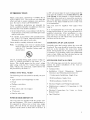
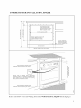
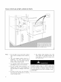
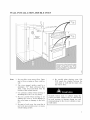
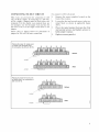
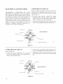
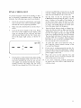
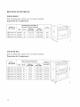
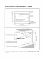
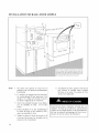
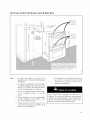
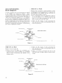
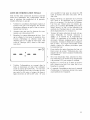
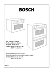
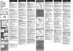
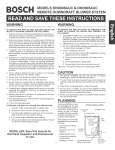
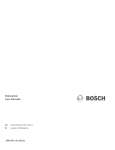
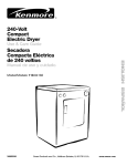
BOSCH
INSTALLATION
INSTRUCTION
for
Bosch Electric Built-in
MANUAL
Single & Double Oven Models HBN 44../45../46..
MANUEL
D'INSTALLATION
four 61ectrique Bosch encastr6,
simple et double
Models HBN 44../45../46..
Ed. 01-02
BOSCH
INSTALLATION
INSTRUCTION
for
Bosch Electric Built-in
MANUAL
Single & Double Oven Models HBN 44../45../46..
BEFORE
YOU BEGIN, READ THESE
INSTRUCTIONS
COMPLETELY
AND CAREFULLY
IMPORTANT:
Save these instructions for the local electrical inspector's use
INSTALLER: Please leave this manual with owner for future reference.
OWNER: Please keep this manual for future reference
Table
INTRODUCTION
TOOLS
.............................................................................................................................
YOU WILL NEED ........................................................................................................
POWER REQUIREMENTS
CHOOSING
STEPS
of Contents
OVEN
.......................................................................................................
LOCATION
FOR INSTALLATION
3
3
3
...............................................................................................
3
..................................................................................................
3
TECHNICAL
DATA .........................................................................................................................
4
SINGLE
OVEN ............................................................................................................................
4
OVEN ..........................................................................................................................
4
DOUBLE
UNDERCOUNTER
SINGLE
WALL
INSTALLATION
OVEN ............................................................................................................................
INSTALLATION
SINGLE
DOUBLE
ELECTRICAL
WIRING
.................................................................................................................
5
5
6
OVEN ............................................................................................................................
6
OVEN ..........................................................................................................................
7
SUPPLY
..................................................................................................................
REQUIREMENTS
CONNECTING
ELECTRICAL
..........................................................................................
......................................................................................................
TO 208 VOLT
CONNECTIONS
CIRCUIT
...............................................................................
8
8
9
...................................................................................................
10
3-WIRE
BRANCH
CIRCUIT
.....................................................................................................
10
4-WIRE
BRANCH
CIRCUIT
.....................................................................................................
10
FINAL
CHECKLIST
........................................................................................................................
11
INTRODUCTION
Please
read
these
instructions
COMPLETELY
AND CAREFULLY.
They will save you time and
effort and help to ensure optimum oven performance. Be sure to observe all WARNINGS.
These
installation
instructions
are
use by a qualified installer. In addition
structions the oven shall be installed:
intended
for
to these in-
• In the United States, in accordance
with the National Electric Code/State
and Municipal codes
and/or local codes.
• In Canada, in accordance
with Canadian
tric Code C22.1-1atest
edition/Provincial
Municipal
codes and/or
These shall be carefully
Note:
Elecand
followed
at all times.
The UL Canadian listing mark consists of the circled UL symbol preceded
by the letter "C", as
shown. This should appear on the oven's rating
plate along with the UL United
States listing
mark, which is the circled UL symbol above but
not preceded by the letter "C".
YOU
The following
oven:
• Tape measure
WILL
tools are needed to install your new
and straightedge
• Level
•
and wire stripper
1" hole saw
• Hand or saber saw.
POWER
be supplied
with
copper
wires
It is recommended
that you have the electrical
wiring and hook-up of your oven performed
by a
qualified
electrician.
After installation
is complete have the electrician
show you where the
main disconnect
is and which of the circuit breakers/fuses are for the oven.
CHOOSING
OVEN
LOCATION
Carefully select the location where the oven will
be placed. The oven should be located for convenient use in the kitchen, but away from strong
drafts. Strong drafts may be caused by open doors
or windows, or by heating
and/or air conditioning
vents or fans. Make sure that electrical power can
be provided to the location selected.
STEPS
FOR
INSTALLATION
The following pages provide the necessary information for proper installation
of the oven arranged as tk_llows:
• Technical
Data
Cutout
Dimensions,
and Mounting instructions
> Undercounter
Installation,
Required
tk_r:
Single Oven
>Wall Installation,
Single Oven
>Wall Installation,
Double
or ruler
screwdriver
• Wire cutters
must
• Installation
Clearances
NEED
• Pencil
• Phillips
The oven
ONLY.
local codes.
If installing your oven in Canada please
check to make sure that you have a model
with the UL Canadian
listing mark, as
shown below:
TOOLS
a 208 volt circuit must be used, wiring inside the
oven must be modified. See Connection
to a 208
Volt Circuit, in this manual. A circuit breaker or
time-delay
fuse sized not to exceed the circuit rating of the appliance
specified on the rating plate
located on the frame behind the door of the oven
is recommended.
REQUIREMENTS
The oven must be supplied with the proper voltage and frequency.
The oven is manut:actured
to
be connected
to a three wire or four wire, single
phase, 240 volt, 60 Hz AC electrical supply on a
separate circuit fused on both sides of the line. If
• Electrical
Supply
• Modifications
Volt Circuit.
and Wiring
required
• Electrical
Connections
Branch Circuit.
• Final Checklist.
Oven
Requirements
if Connecting
for
3-wire
to 208
or
4-wire
TECHNICAL
SINGLE
DATA
OVEN
For cutout
dimensions
Preparing
Location
see following
sections
Electrical
Ratings
and Maximum
Connected
Single Oven
Models
Load
Watts
@240V/208V
Convection
Oven
Volts
Hertz
HBL 442A UC
240/208
60
13.5/13.6
3,250/2,820
Yes
HBL 445A UC
240/208
60
13.5/13.6
3,250/2,820
Yes
HBL 446A UC
240/208
60
13.5/13.6
3,250/2,820
Yes
DOUBLE
OVEN
For cutout
dimensions
Preparing
Location
Amperes
@240V/208V
titled:
see following
sections
Electrical
Ratings
and Maximum
Connected
Double Oven
Models
Volts
titled:
Load
Convection
Oven
Watts
(top/bottom)
?I!240V/208V
Hertz
Amperes
_I!240V/208V
HBN 452A UC 240/208
60
26/26
6,250/5,400
Yes/No
HBN 455A UC 240/208
60
26/26
6,250/5,400
Yes/No
HBN 456A UC 240/208
60
26/26
6,250/5,400
Yes/No
HBN 462A UC 240/208
60
26/26
6,250/5,400
Yes/Yes
HBN 465A UC 240/208
60
26/26
6,250/5,400
Yes/Yes
HBN 466A UC 240/208
60
26/26
6,250/5,400
Yes/Yes
J
J
UNDERCOUNTER
INSTALLATION,
SINGLE
I
I
Oven electrical supply:
Locate junction box in
adjacent cabinet or below
bottom support surface.
i
2:
25-3/8" opening
I
¥
_
width
I
I
co
I
Bottom support surface must
be solid level and able to
support at least of 150 Ibs,
!/4' min. distance
between oven door
frame and adjacent
doors or drawer fronts.
w
toe space area
26-5/8'
maintain
width of oven door frame
Note: Decorative inserts must
minimum spacing as shown.
Secure
oven to cabinet
using the screws
provided. Screws should be inserted through the
mounting
holes in the positions indicated in the
frame (open door to see frame and mounting
holes), Do not overtighten screws,
maintain
Note: Decorative inserts must
minimum spacing as shown.
Refer to and follow Notes
and Warning
listed under Wall Installation,
Single Oven
(facing
page)
WALL
INSTALLATION,
SINGLE
OVEN
25-3/8" opening
width
c
_.-
Electrical
o=¢
supply
junction
Note:
l. Do not slide oven across
age to floor covering
sult.
box
floor.
Dam-
or floor could
re-
2. The oven support surt:ace must be a
minimum
3/4" thick plywood
platform, solid, level and flush with the
bottom of the cabinet cutout.
3. Use extreme caution when moving
installing the oven. It is very heavy.
or
4. Be very careful when moving or installing the oven to avoid damage to
the oven frame or damage to the cabinets.
5. Be sure to level oven. An oven that is
not level may provide
sistent baking results.
poor
6. Be careful when placing
oven. DO
NOT pinch the conduit between
the
oven back or wall and the inner cabinet wall or floor.
or incon-
Securely
t:asten oven to cabinet
using the
screws provided. Failure to do so could result
in oven moving or tipping during use and
causing damage to the oven or cabinets or personal injury.
WALL INSTALLATION,
DOUBLE
OVEN
i
Secure oven to cabinet usingthe
screws
provided.
Screws
should be inserted
through
the mounting
holes
in the
positions
indicated
in the frame (open
door to see frame and mounting
holes).
Do not overtighten screws,
Note:
1. Do not slide oven across floor. Damage to floor covering or floor could result.
2. The oven support surt:ace must be a
minimum
3/4" thick plywood
platform, solid, level and flush with the
bottom of the cabinet cutout.
3. Use extreme caution when moving
installing the oven. It is very heavy.
or
4. Be very careful when moving or installing the oven to avoid damage to
the oven frame or damage to the cabinets.
5. Be sure to level oven. An oven that is
not level may provide
sistent baking results.
6. Be careful when placing
oven. DO
NOT pinch the conduit between
the
oven back or wall and the inner cabinet wall or floor.
poor or incon-
Securely
fasten oven to cabinet
using the
screws provided. Failure to do so could result
in oven moving or tipping during use and
causing damage to the oven or cabinets or personal iniury.
ELECTRICAL
SUPPLY
WIRING
Before installing the oven have a qualified electrician verify that your home is provided with adequate electrical service and that the addition of
the oven will not overload the branch circuit on
which it is to be installed. A separate three-wire
or four-wire single phase, 240 Volt, 60 Hz., or a
208 Volt, 60 Hz. branch circuit is required.
Note:
For use with 208 V, 60 Hz supply voltage
the wiring must be modified as shown in
Connecting to 208 Volt Circuit.
REQUIREMENTS
When making the wire connections,
use the entire
length of the conduit provided (3 feet). The conduit must not be cut.
Before making connections
is off and read and observe
make sure the power
the following:
1.
A separate
three-wire
or four wire, single
phase, 240 Volt, 60 Hz. or 208 Volt, 60 Hz
branch circuit is required for the oven.
2.
The oven must
WIRE ONLY.
3.
In the United
be connected
with COPPER
States:
For hook-up of the oven you will need to have an
approved junction box installed where it will be
easily reached through the front of the cabinet
where the oven will be located. The oven has 3
feet of conduit. Allow two to three feet of slack in
Wiring must conform to the National Electrical Code, ANSI/NFPA
No. 70 latest edition.
You can obtain a copy of the National Electrical Code by writing:
National Fire Protection Association
the line so that the oven can be moved if servicing
is ever necessary.
DO NOT shorten the flexible
conduit.
Batterymarch
Park
Quincy, MA 02269
In Canada:
Wiring must conform to Canadian Electrical
Code C22.1- latest edition. You can obtain
ELECTRICAL
SHOCK
copies of the Canadian
writing:
HAZARD
made.
• Do not use an extension
pliance.
cord with this ap-
• Electrical
ground is required on this appliance. The free end of the green wire (the
ground wire) must be connected
to a suitable ground.
This wire must remain grounded
to the
oven.
• If cold water pipe is interrupted
by plastic,
non-metallic
gaskets, union connections
or
other insulating materials, DO NOT use for
grounding.
• DO NOT ground to a gas pipe.
• DO NOT have a fuse in the NEUTRAL
or
GROUNDING
circuit. A fuse in the NEUTRAL or GROUNDING
circuit could result
in an electrical shock.
• Check with a qualified electrician
if you are
in doubt as to whether
the appliance
is
properly grounded.
Failure to follow these instructions
could result in serious
injury or death.
Code
by
Canadian Standards Association
178 Rexdale Boulevard
Rexdale (Toronto), Ontario, Canada
M9W 1R3
• The electrical power to the oven branch circuit must be shut off while line connections
are being
Electrical
4.
Wire size (COPPER WIRE ONLY) and connections must be suitable for the rating of the
appliance
per the National
Electrical
Code
requirements.
The flexible armored cable extending from the oven should be connected
directly to the junction box.
5.
The junction box should be located so as to
allow as much slack as possible between the
junction box and the oven so it can be moved
if servicing is ever required.
6.
A U.L. listed conduit connector must be provided at each end of the power supply cable.
CONNECTING
To connect
TO 208 V CIRCUIT
The ovens are pre-wired
for connection
to 240
volt, 60 Hertz supply. If connecting
to a 208 volt,
60 Hz. supply a jumper must be used across two
terminals.
For the double oven models there are
two jumpers, one for the upper oven and one for
the lower oven. For the single ovens there is one
jumper.
Please
jumper
refer to figures below for placement
for 208 volt, 60 hertz connection.
to 208 volt circuit:
1
Remove the access
back of the oven(s).
2.
Loosen the first and second screws in the terminal block as shown in applicable
figure
above.
3.
Place the metal jumper
and second
screws and
hold jumper
in place.
4.
Replace
of
access
panel(s)
Placing of jumper for single oven
or upper oven of double oven,
for connection
to 208 volt, 60 Hz.
Before
After
Jumper
Placing of jumper for lower oven
of double oven, for connection to
208 volt, 60 Hz.
Before
Jumper
After
Jumper
on the
between
the first
tighten
screws
to
panel(s).
Jumper
located
ELECTRICAL
This appliances
GROUND
wire
3-WIRE
CONNECTIONS
CIRCUIT
Refer to Figure A, where local codes allow the
connection
of GROUND
wire from the oven to
is manufactured
with a green
connected
to the oven chassis.
the branch circuit
colored wire):
After making sure that the power has been turned
off connect the flexible conduit from the oven to
NEUTRAL
wire (grey or white
• If local
codes
permit,
connect
the green
GROUND
wire from the oven and the white
wire from the oven to the branch circuit NEU-
the junction box using a U.L. listed conduit connector. Figures A and B and the instructions
provided below present the most common
way of
connecting
the ovens. Your local codes and ordinances, of course, take precedence
to these instructions.
Complete
electrical
connections
according to local codes and ordinances.
Junction box _
BRANCH
TRAL wire (grey or white colored
• Connect
the red and black
to the corresponding
wire).
leads from the oven
leads in the junction
box.
CaNe from
suppUy
_er
Whitewires
Red wires.
_
__
Bare o_
_
"BHack wires
CaMe
from
_
BRANCH
U.L.-Iisted conduit connector
oven
Figure
4-WIRE
Neutram
Grounded
A.
• Connect
CIRCUIT
the red and black
to the corresponding
Refer to Figure B:
• Connect
• Connect
the green GROUND
wire from the
oven to the GROUND wire in the junction box
(bare or green colored wire).
Junction
box
CaNe
_-_.
the white
NEUTRAL
box.
leads in the junction
wire
from
power
suppHy
White
wires
BHack wires
wures
CabHe
from
_.
oven
Figure
10
from
(grey or white)
Ungrounded
Bare or green
leads from the oven
_
B.
U.LMisted
conduit
connector
Neutram
the oven
box.
to the
wire in the junction
FINAL
CHECK
LIST
you have modified the oven(s) for use on 208
volt the voltage reading between the black
and red wires should be 190 to 208 volts.
To prevent improper connections
leading to damage of electrical components
and so voiding the
warranty, the following steps must be performed:
1.
2.
3.
5.
Check the electrical
requirements
and make
sure you have the correct electrical
supply
and that the oven is properly grounded.
Make sure all control
sition.
6.
Turn the Mode Selector knob to Manual position, the Selector knob to Bake and turn the
Temperature
knob to 350 °F. The cooling
fan, the oven lights and the heat light should
come on to indicate that the oven is heating.
The heat light will turn off when the set temperature (350 °F) is reached. Turn Temperature knob to off. If you have installed a double oven repeat test tk_r second oven.
7.
To check the other oven functions
refer to
the Using the Oven Controls section of the
Use and Care Manual.
8.
If the oven is working properly turn the Selector knob(s) and the Temperature
Control
knob(s) to their off positions and turn off the
power supply to the oven.
9.
Place the cover on the junction
box
make sure the cover is securely fastened
turn on the power to the oven.
10.
Leave these INSTALLATION
instructions
as well as the USE AND CARE MANUAL
with the owner.
Turn on the power supply to the oven. When
the oven is first turned on the display will
come on showing all the call-outs and then
will become blank with the Set Clock symbol in the upper right corner, as shown below.
0
@
J
.
Check power at the junction box wires using
a volt meter having a range of 0-250 VAC. If
you have installed the oven for use on 240
volt supply you should find that the voltage
reading
between
the black and red wires
(Line to Line) should be 220 to 240 volts. If
pressing
the Set
the plus (+) or miof the display to
the time is set de-
press the Set Clock button to enter the time.
A "beep" will sound and the Set Clock symbol in the upper right will disappear.
knobs are in the off po-
SET (_
Set the time of day by
Clock button and pressing
nus (-) button, to the right
set the correct time. Once
and
and
11
BOSCH
MANUEL
D'INSTALLATION
four 61eetrique
Bosch eneastr6,
Models HBN 44../45../46..
VEUILLEZ
simple
et double
LIRE ATTENTIVEMENT
CE MANUEL
L'INSTALLATION
IMPORTANT:
Conservez
ce manuel
pour
AVANT
l'inspecteur
DE COMMENCER
61ectrique
local.
INSTALLATEUR:
Veuillez remettre
ce manuel
au propri6taire
de l'appareil
pour r6f6rence.
PROPRII_TAIRE:
Veuillez garder
ce manuel
et vous en servir pour r6f6rence.
Table
INTRODUCTION
OUTILS
.............................................................................................................................
DONT
VOUS AUREZ BESOIN ................................................................................
SPECIFICATIONS
CHOIX
DE L'INSTALLATION
DONNI_ES
FOUR
ELECTRIQUES
DE L'EMPLACEMENT
ETAPES
TECHNIQUES
REQUISES
....................................................................
INSTALLATION
INSTALLATION
15
..........................................................................................................................
FOUR DOUBLE
ALIMENTATION
LES CONNEXIONS
...........................................................................................................
16
16
16
17
17
18
............................................................................................................................
18
..........................................................................................................................
19
EN I_LECTRICITI_
FILS t_LECTRIQUES
CONNEXION
....................................................................................
...........................................................................................................................
FOUR SIMPLE
15
..............................................................................................
..............................................................................................................
MURALE
15
15
SOUS LE COMPTOIR
FOUR SIMPLE
15
DU FOUR ............................................................................
SIMPLE ............................................................................................................................
FOUR DOUBLE
REQUIS
A UN CIRCUIT
........................................................................................
20
.................................................................................................
20
A 208 VOLTS
21
I_LECTRIQUES
.......................................................................
..........................................................................................
22
CIRCUIT
)t 3 FILS .....................................................................................................................
22
CIRCUIT
)t 4 FILS .....................................................................................................................
22
LISTE
14
des mati_res
DE ¥1_RIFICATION
FINALE
..........................................................................................
23
INTRODUCTION
Veuillez lire enti_rement
et attentivement
les instructions
contenues dans ce manuel.
Cela vous
permettra
de gagner
du temps et d'obtenir
de
meilleurs rdsultats de votre four. Prenez soin de
respecter toutes les MISES EN GARDE.
Les instructions
d'installation
sont destin@s/_
un
installateur
qualifid.
En plus de ces instructions,
le four dolt etre installd comme suit:
• Aux i_tats-Unis, conformement
aux Normes
lectriques
nationales/Normes
provinciales
municipales
et/ou Normes locales.
eet
• Au Canada,
conformement
au normes
canadiennes de l'electricite,
Code C22.1-derni_re
edition/Normes
provinciales
et
municipales
et/ou normes locales.
Ces normes
Note:
doivent
etre respect@s
SOUS_
Ce symbole canadien UL consiste en un cercle
dans lequel sont inscrites les lettres UL et le tout
est precede d'un "C". Ce signe doit apparaitre sur
la plaque de specifications
du four, accompagne
du symbole americain
(mame dessin UL, mais
non precede du "C").
DONT
VOUS
AUREZ
Pour installer votre nouveau
soin des outils suivants:
• Un ruban il mesurer
BESOIN
four, vous aurez be-
et une ragle.
• Un crayon.
• Un tournevis
positif principal
disjoncteur/fusible
de debranchement
du four.
et quel est le
en tout temps.
Sice four est installe au Canada, veuillez
vous assurer que votre module comporte
le symbole canadien UL indique ci-des-
OUTILS
une source de courant alternatif
(C.A.) separde,
par un circuit/_ trois ou quatre ills/_ phase unique,
240 volts, 60Hz. Si vous devez utiliser un circuit
de 208 volts, il faut absolument
modifier le filage
/_ l'interieur
du tour. Refdrez-vous/_
Connexions
'a un circuit de 208 volts, dans ce manuel.
I1 est
recommande
d'avoir un disjoncteur
ou un fusible
emp@hant
l'appareil
d'aller au-deli_ des limites
indiquees sur la plaque de specifications
fix@ sur
le cadre du four, derribre la porte.
Ce four dolt etre connecte /_ l'aide de ills electriques en cuivre SEULEMENT.
Nous vous recommandons
de faire installer
et
brancher votre four par un electricien
qualifie.
Aprbs que l'installation
est achevee,
demandez
/_
l'electricien
de vous montrer o/1 se trouve le dis-
CHOIX
DE L'EMPLACEMENT
DU FOUR
Choisissez avec soin l'endroit oO vous placerez le
four. I1 devrait etre facile d'ac@s dans la cuisine,
mais loin des courants d'air.
Les courants d'air
sont causes par des portes ou fenetres ouvertes, ou
encore par le chauffage et/ou la climatisation/ventilation.
Assurez-vous
que l'endroit
que vous
avez choisi peut facilement _tre alimentd en dlectricite.
l_TAPES
DE L'INSTALLATION
Vous trouverez
dans les pages qui suivent
description,
etape par etape, de l'installation
votre tour. En voici les principaux
elements:
• Donnees techniques
• Dimensions
de l'emplacement,
quis et instructions
de montage
une
de
espacements
pour:
> une installation
sous le comptoir,
> une installation
murale,
tkmr simple
> une installation
murale,
four double
re-
four simple
Phillips.
• Un niveau/_
bulle d'air.
• Un coupe-ill
lectrique.
electrique
et un denudeur
de fil e-
• Une scie pour trous de 1".
en electricite
• Modifications
208 volts.
necessaires
• Connexions
ou/_ 4 ills
• Un scie manuelle.
SPI_CIFICATIONS
• Alimentation
I_LECTRIQUES
electriques
• Liste de verification
et filage requis
pour
un
circuit
pour un circuit/_
de
3 ills
finale
REQUISES
Le four doit _tre alimente par un courant de voltage et de frequence
adequats.
I1 doit etre relie /_
15
DONNI_ES
FOUR
TECHNIQUES
SIMPLE
Pour les dimensions,
Prdparation
Mod61es
four
rdfdrez-vous
_ la section intitulde
de l'emplacement
Spdcifications
dlectriques
et
charge dlectrique
maximale
h
simple
Four it
convection
Hertz
Amperes
240V/208V
Watts
240V/208V
HBN 442A UC 240/208
60
13.5/13.6
3,250/2,820
Oui
HBN 445A UC 240/208
60
13.5/13.6
3,250/2,820
Oui
HBN 446A UC 240/208
60
13.5/13.6
3,250/2,820
Oui
FOUR
Volts
DOUBLE
Pour les dimensions,
Prdparation
rdfdrez-vous
il la section intitulde
de l'emplacement.
Spdcifications dlectriques et
charge dtectrique maxilnale
ModUles ii
four double
Volts
Hertz
240V/208V
Watts
240V/208V
Amperes
Four '_
convection
(haut/bas)
HBN 452A UC 240/208
60
26/26
6,250/5,400
Oui/Non
HBN 455A UC 240/208
60
26/26
6,250/5,400
Oui/Non
HBN 456A UC 240/208
60
26/26
6,250/5,400
Oui/Non
HBN 462A UC 240/208
60
26/26
6,250/5,400
Oui/Oui
HBN 465A UC 240/208
60
26/26
6,250/5,400
Oui/Oui
HBN 466A UC 240/208
60
26/26
6,250/5,400
Oui/Oui
16
/
J
INSTALLATION
SOUS
w
LE COMPTOIR,
SIMPLE
I
I
dO
FOUR
Alimentation
en electrique du four:
Localisez la bo'ite de derivation dans
larmoire adjacente ou sous la surface
de support inferieure,
I
I
I
I
25-3/8'
I
Largeur
de Iouverture
I
I
I
I
I
O3
I
La surface de support inferieure dolt
@re solide, de niveau et capable de
supporter au moins !50 Ibs,
1/4 ' min. de distance
entre le cadre de la
porte du four et les
portes au tiroirs adjacents.
Espace
26-5/8 ' Largeur
de la butee
du cadre de la porte du four
Note: les panneaux decoratifs doivent maintenir
le minimum d'espace requis, tel quindique.
Fixez le four & I armoire & laide des vis fournies.
Les vis doivent @re inser6es dans les trous de
montage, dans les positions indiquees
sue le
cadre (ouvrez la porte pour voir le cadre et les
trous de montage), Ne serrez pas les vis trop
fort,
Note: les panneaux decoratifs doivent maintenir
le minimum d'espace requis, tel quindique.
Veuillez vous rdfdrer aux notes
(page opposde).
et mises en garde
mentionndes
sous. Installation
murale,
four
simple
17
INSTALLATION
MURALE,
FOUR
SIMPLE
25-3/8"
Large
de Pouverture
/
©
Fixez le four a I'armoire a I'aide des vis fournies.
Les vis doivent 8tre ins6r6es dans les trous de
montage, dans les positions indiqu6es sur le cadre (ouvrez la porte pour voir le cadre et les trous
de montage). Ne serrez pas les vis trop fort.
o
Note:
1. Ne faites pas glisser
le tour sur le
plancher car cela pourrait endommager
le plancher.
2. La surface de support du tour doit etre
en contre-plaqud
d'une dpaisseur d'au
moins 3/4", solide, de niveau et encastrd dans l'alignement
de l'armoire.
3. Soyez tr_s prudent lorsque
cez ou installez
le four.
lourd.
le four, prenez soin de ne
le conduit entre l'arribre
lemur et la paroi de Farplancher.
bien le four/_
l'armoire/_
vous ddplaI1 est tr_s
4. Faites attention /_ ne pas endommager
le cadre du four ou les armoires, lorsque vous installez le four.
5. Veillez/_ placer le four de niveau. S'il
n'est pas de niveau, les rdsultats de la
cuisson s'en ressentiront.
18
6. En placant
pas coincer
du four ou
moire ou le
Fixez
l'aide
des vis
fournies. Si vous ne le t:aites pas, cela pourrait
rdsulter en un ddplacement
ou un basculement
du four et pourrait endommager
le tour, les armoires ou encore causer des blessures.
INSTALLATION
MURALE,
FOUR
DOUBLE
Fixez le four & larmoire & laide des vis fournies.
Les vis doivent @re inserees dans les trous de
montage, dans les positions indiquees sur le cadre (ouvrez la porte pour voir le cadre et les trous
de montage). Ne serrez pas les vis trop fort.
Note:
6. En placant le four, prenez soin de ne
pas coincer le conduit entre l'arriare
du four ou lemur et la paroi de Farmoire ou le plancher.
1. Ne faites pas glisser
le four sur le
plancher car cela pourrait endommager
le plancher.
2. La surface de support du tour doit etre
en contre-plaqud
d'une dpaisseur d'au
moins 3/4", solide, de niveau et encastrd dans l'alignement
de l'armoire.
3. Soyez tr_s prudent lorsque
cez ou installez
le four.
lourd.
vous ddplaI1 est tr_s
4. Faites attention /_ ne pas endommager
le cadre du four ou les armoires, lorsque vous installez le four.
Fixez
bien le four/_
l'armoire/_
l'aide
des vis
fournies. Si vous ne le t:aites pas, cela pourrait
rdsulter en un d@lacement
ou un basculement
du four et pourrait endommager
le four, les armoires ou encore causer des blessures.
5. Veillez/_ placer le four de niveau.
S'il
n'est pas de niveau, les rdsultats de la
cuisson s'en ressentiront.
19
ALIMENTATION
EN
FILS
I_LECTRICITI_
Avant d'installer
le four, demandez
/_ un electricien qualifie de verifier que votre maison dispose
d'un service electrique
adequat et que le rajout
d'un tour ne surchargera
pas le circuit.
Un circuit
separe, /_ trois ou quatre ills, /_ phase unique, 240
volts, 60Hz, ou 208 volts, 60 Hz est requis.
Note:
Si vous utilisez un circuit de 208 volts, 60
Hz, il faut modifier le filage tel qu'indique dans: Connexions
'3 un circuit de
208 volts.
I_LECTRIQUES
REQUIS
Lors des connexions
des ills de votre appareil, utilisez toute la longueur
du conduit
electrique
foumi (3 pieds). Ne coupez pas ce conduit.
Avant de brancher l'appareil/_
la source d'electricite, assurez-vous
que le courant est coupe et suivez les instructions
ci-dessous:
1.
Un circuit distinct /_ trois ou quatre ills, /_
phase unique, 240 volts, 60Hz, ou 208 volts,
60 Hz est requis pour ce tkmr.
2.
Le four doit atre connecte/_
3.
Aux l_tats-Unis:
lectriques
en cuivre
l'aide
de ills e-
SEULEMENT.
Le filage doit _tre conforme
aux Normes electriques nationales,
et/_ la dernibre edition
de I'ANSI/NFPA
No 70. Pour obtenir une
Pour brancher
le four, vous devrez placer une
boite de derivation
/_ un endroit facile d'ac@s, il
l'interieur
de l'armoire
o/1 est place le four. Le
four est muni d'un conduit de 3 pieds de long.
Laissez deux ou trois pieds de fil lfiche pour que
le tour puisse atre facilement
deplace en cas de
reparation.
NE RACCOURCISSEZ
PAS le
conduit flexible.
copie du Code
la demande/_:
National
electrique
Fire Protection
National,
faites-en
Association
Batterymarch
Park
Quincy, MA 02269
Au Canada:
DANGER
DE CHOC
I_LECTRIQUE
• Le courant electrique alimentant
etre coupe durant le branchement.
le four doit
• N'utilisez
pas de rallonge
electrique
avec
cet appareil.
• Cet appareil necessite une mise /_ la terre.
L'extremite
du fil vert (ill de mise /_ la
terre) doit atre reliee /_ une mise /_ la terre
adequate.
Ce fil electrique doit rester relie au four.
• Si les tuyaux d'eau froide comportent
des
parties en plastique,
des joints non-metalliques ou d'autres
materiaux
isolants,
NE
LES UTILISEZ PAS pour la mise/_ la terre.
• N'UTILISEZ
PAS DE TUYAUX DE GAZ
pour la mise/_ la terre.
• Ne placez pas de fusible sur le fil NEUTRE
ou le fil de MISE A LA TERRE.
Un tel fusible pourrait resulter en un choc electrique.
• Si vous avez le moindre doute, faites verifier par un electricien
que votre appareil est
bien mis/_ la terre.
Le fait de ne passe
tions peut entrainer
la mort.
2O
Le filage doit
nadiennes
de
niare edtion.
canadien
de
mande/_ :
conformer/_
de serieuses
ces instrucblessures ou
atre conforme aux Normes cal'electricite,
Code C22.1 - derPour obtenir une copie du Code
l'electricite,
faites-en
la de-
Canadian Standards Association
178 Rexdale Boulevard
Rexdale (Toronto), Ontario, Canada
M9W 1R3
4.
Le calibre des ills (EN CUIVRE SEULEMENT) et les connexions doivent atre approprides au type d'appareil et conformes aux
exigences des Normes electriques nationales.
Le cfible flexible sortant du tour dolt atre relid directement/_ la boite de derivation.
5.
La boite de derivation dolt atre placee de maniare /_ permettre une certaine liberte de
mouvement du four, au cas o/l on ait/_ deplacer l'appareil pour reparation.
6.
Un connecteur marque UL dolt atre place /_
chaque extremite du cfible d'alimentation electrique.
CONNEXION
A UN CIRCUIT
A
Pour une telle connexion,
effectuez
ce qui suit:
208 VOLTS
1
Les tours
sont equipes
de filage
pour
une
connexion
/_ un circuit de 240 volts, 60 Hz. Si
vous avez l'intention
de le brancher /_ un circuit
Enlevez
l'arriare
2.
Devissez
legarement
la premiare
et la
deuxiame vis du bloc du terminal, tel qu'illustre ci-dessous.
3.
Placez le cfible en mdtal entre
et la deuxi6me
vis et resserrez
de 208 volts, vous devrez placer un cfible entre
deux terminaux. Pour les modbles/_ fours doubles,
il faudra deux cfibles, un pour le four du haut et
un autre pour le four du bas. Veuillez vous refdrer
aux illustrations
ci-dessous pour l'installation
des
cfibles necessaires
/_ un circuit de 208 volts,
60 Hz.
Installation
du
four simple ou
d'un modele a
une connexion
volts,
le(s) panneau(x)
du(des) four(s).
que le cfible reste
4.
Replacez
d'accas
situes
il
la premi6re
les vis afin
en place.
les panneaux
d'acc_s.
c&ble pour un
le four superieur
four double, pour
a un circuit de 208
60 Hz.
Avant
Pont
Apr_s
Pont
Installation
du c_ble pour le four
inferieur d'un modele a four double,
208 volts, 60 Hz.
pour une connexion
a un circuit
de
Avant
U
Pont
Apr_s
Pont
21
CIRCUIT
LES CONNEXIONS
I£LECTRIQUES
Refdrez-vous/_ la figure A pour laquelle les codes
et rbglements, locaux permettent la connexion du
fil de MISE A LA TERRE du four au fil du circuit NEUTRE (fil blanc ou gris):
• Si les rbglements locaux le permettent, reliez le
fil vert de MISE A LA TERRE provenant du
four et le fil blanc provenant du four, au fil
blanc ou gris du circuit NEUTRE.
Ce four est fourni avec un fil electrique de MISE
LA TERRE vert, rattache au chfissis. Apr_s
vous etre assure que le courant est coupe, reliez le
conduit flexible du four/_ la boite de derivation/_
l'aide d'un connecteur approuve U.L. Les figures
A et Bet les instructions suivantes presentent le
moyen le plus commun de brancher les tours. Les
normes et r_glements locaux regissant l'electricite
ont cependant preseance sur ces instructions. Effectuez les connexions electriques conformement
aux codes et r_glements locaux.
Botte
de derivation
• Reliez les fils rouges et noirs provenant du
four, aux fils de couleur correspondante dans la
boite de derivation.
C&bUe d'aUimentation
--.
Fils
A 3 FILS
61ectrique
Fils rouges _
_Fils
CfbUe venant
du four
Figure
CIRCUIT
A 4 FILS
ReKrez-vous/_
_-
noirs
Connecteur
approuv_
U.L. CSA
A.
• Reliez les fils rouges et noirs provenant du
four, aux fils de couleur correspondante dans la
boite de derivation.
la figure B:
• Reliez le fil vert de MISE A LA, TERRE, provenant du four, au fil de MISE A LA TERRE
dans la boite de derivation (fil denude ou de
couleur verte).
Boite de d6dvation
• Reliez le fil blanc provenant du four au fil
NEUTRE (gris ou blanc) dans la boite de derivation.
C&bUe d'aUimentation
_Uectrique
_.
_.
Fils Mancs
Neutre non misa
la terre
Fil vert ou dOnud6
C&ble venant
du four
_.
" Connecteur
Figure
22
B.
approuve
U.L. CSA
LISTE
DE VITRIFICATION
FINALE
Afin d'eviter toute connexion
incorrecte
pouvant
causer des dommages
aux composantes
electriques et entrainer une annulation
de la garantie,
veuillez effectuer ce qui suit:
1.
Verifiez les conditions electriques requises et
assurez-vous
que vous disposez des articles
electriques adequats et que le four est correctement mis/_ la terre.
2.
Assurez-vous
que tous les boutons
mande sont/_ la position OFF.
3.
Branchez
le courant
alimentant
avez modifie le tour pour un circuit de 208
volts, la lecture doit alors atre entre 190 et
208 volts.
5.
Reglez l'horloge
en appuyant
sur le bouton
Set Clock et en appuyant
sur les boutons
plus (+) ou moins (-), il droite de l'afficheur.
Une fois que l'heure juste est atteinte, appuyez sur le bouton Set Clock pour introduire l'heure. Un "bip" se fera entendre et le
symbole de l'horloge
dans le coin superieur
droit disparaitra.lus
(+) or minus (-).
6.
Tournez le bouton selecteur de mode/_ la position
Manuelle,
le bouton
selecteur
/_
"Bake"
et le bouton de la temperature
/_
3505F. Le ventilateur
et les lampes du four
devraient s'allumer,
indiquant que le tour est
en marche. Tournez le bouton de la temperature/_ "OFF". S'il s'agit d'un modale/_
four
double, repetez les mames procedures
pour
le deuxiame four.
7.
Pour verifier les autres fonctions du tour, refdrez-vous/_
la section "Utilisation
des commandes du tour" dans le manuel d'utilisation
et d' entretien.
8.
Si le four fonctionne
bien, remettez les boutons selecteurs et le bouton de la temperature
/_ la position OFF, puis coupez le courant.
9.
Replacez le couvercle
de la boite de derivation, assurez-vous
qu'il est bien fixe et rebranchez le courant.
10.
Ce manuel
d'utilisation
de com-
le tour.
Lor-
qu'on allume le four pour la premiere
fois,
l'ecran
d'affichage
va afficher
toutes les
donnees puis vase vider de tout signe, sauf
celui de l'horloge
(SET) dans le coin superieur droit.
O
O
,
Verifiez
l'alimentation
en courant dans la
boite de derivation
/_ l'aide d'un voltmatre
ayant un rayon de 0-250 VAC. Si vous ates
sur un circuit de 240 volts, la lecture du voltage entre les ills noirs et rouges (de ligne /_
ligne) doit atre de 220/_ 240 volts. Si vous
d'installation
ainsi que le manuel
et d'entretien
doivent atre remis
au proprietaire
de l'appareil.
23
Code 09BH0300
TPS Gallarate-
(02-001)