1
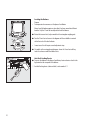
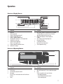
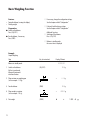
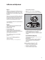
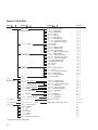
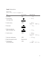
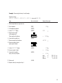
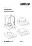
Operating Instructions
ACCULAB ATILON
Electronic Analytical and Precision Balances
98648-016-08
Contents
3 Warnings and Safety Precautions
43 ISO/GLP-compliant Printout/Record
4 Getting Started
45 Data Interface
5 Installation
46 Troubleshooting Guide
11
11
12
13
Operation
Display and Operating Elements
Basic Weighing Function
Calibration and Adjustment
16
16
17
18
19
23
Configuration (Operating Menu)
Functions of the Keys during Configuration
Menu Navigation; Example: Setting the Language
Parameter Settings: Menu
Parameter Settings: Overview
Input: ID Number, Date and Time
26
26
28
30
32
34
36
38
40
Application Programs
Counting
Weighing in Percent
Calculation
Animal Weighing/Averaging
Net-total Formulation
Totalizing
Density Determination
Mass Unit Conversion
2
47 Care and Maintenance
48 Recycling
49
50
52
53
Overview
Specifications
Accessories
C Marking
Warnings and Safety Precautions
Safety
§ To prevent damage to the equipment, please read these
operating instructions carefully before using the balance.
! Do not use this equipment in hazardous locations.
! The balance may be opened only by trained service
technicians.
! Disconnect the balance from power before connecting or
disconnecting peripheral devices.
! If you operate the balance under ambient conditions
subject to higher safety standards, you must comply with
the applicable installation regulations.
! Exposure to excessive electromagnetic interference can
cause the readout value to change. Once the disturbance
has ceased, the instrument can be used again in
accordance with its intended purpose.
Make sure that no liquid enters the equipment housing;
use only a slightly moistened cloth to clean the balance.
– Connect only Acculab accessories, as these are optimally
designed for use with your Atilon balance. The operator
shall be solely responsible for installation and testing of any
modifications to Acculab equipment, including connection
of cables or equipment not supplied by Acculab. On request,
Acculab will be happy to provide information on operating
specifications (in accordance with the Standards for defined
immunity to interference).
$ Do not open the balance housing. If the seal is broken,
this will void all claims under the manufacturer’s warranty.
$ If you have any problems with your balance, contact your
local customer service center.
Symbols
The following symbols are used in these instructions:
§ indicates required steps
$ indicates steps required only under certain conditions
> describes what happens after you have performed a
particular step
Installation
! Make sure the voltage rating printed on the power supply
is identical to your local line voltage.
– Proceed with extreme caution when using pre-wired
RS-232 connecting cables, as the pin assignments may
not be compatible with Acculab equipment. Before
connecting the cable, check all pin assignments against
the cabling diagrams and disconnect any lines that are
assigned differently.
– indicates an item in a list
! indicates a hazard
! If there is visible damage to the equipment or power cord,
disconnect the equipment from power and lock it in a
secure place to ensure that it cannot be used for the time
being.
3
Getting Started
Storage and Shipping Conditions
– Do not expose the balance to extreme temperatures,
moisture, shocks, blows or vibration.
Unpacking the Equipment
§ After unpacking the equipment, please check it immediately
for any external damage.
$ If you detect any damage, proceed as directed in the
chapter entitled “Care and Maintenance,” under “Safety
Inspection.”
$ Save the box and all parts of the packaging for any future
transport. Disconnect all cables before packing the balance
for shipping.
–
–
–
–
Equipment Supplied
Balance
Weighing pan
Pan support (only for models with a round weighing pan)
AC adapter
Additional equipment supplied with models
ATL-224, -124:
– Sliding-door draft shield
– Drip/breeze ring
– Draft shield base plate
Additional equipment supplied with models
ATL-623, -423, -153:
– Round glass draft shield with cover
4
–
–
–
–
Installation
Choose a location that is not subject to the following
negative influences:
Heat (heater or direct sunlight)
Drafts from open windows and doors
Excessive vibration during weighing
Excessive moisture
Conditioning the Balance
Moisture in the air can condense on cold surfaces
whenever the equipment is moved to a substantially
warmer place. To avoid the effects of condensation, allow
the balance to sit for 2 hours, at room temperature, before
plugging into AC power.
Installation
§
–
–
–
–
Setting Up the Balance
Instruments with sliding-door draft shield:
Place components inside the chamber in the following order:
Draft shield base plate
Drip/breeze ring
Pan support
Weighing pan
§
–
–
–
–
–
Instruments with a round glass draft ring:
Position the components listed below in the order given:
Place the lower lid on the balance with the raised edge facing upwards
Pan support
Weighing pan
Glass draft ring
Place the upper lid on the draft shield ring with the raised edge facing downwards
Instruments with a round weighing pan
§ Position the components listed below in the order given:
– Pan support
– Weighing pan
Instruments with a rectangular weighing pan:
§ Place the weighing pan on the balance
5
–
–
§
§
Connecting the Balance to AC Power/Safety Precautions
Use only original Acculab AC adapters. For use within
U.S./Canada: part no. 6971413
Europe: part no. 6971412
1) Connect the angle plug to the balance
2) Connect the AC adapter to the wall outlet (mains)
AC Adapter with Country-specific Power Cord
Some models come with separate country-specific power cords for the
AC adapter.
§ 1) Connect the angle plug to the balance
§ 2) Select the power cord for your area and connect it to the AC adapter
§ 3) Plug the power cord into the wall outlet (mains)
Use an original Acclulab AC adapter with a wide input voltage range
$ (100 to 240 V~), order no. 6971966, and replaceable power cord:
6900901 (US/CDN)
6900905 (AUS)
6971945 (UK)
6900902 (ZA)
6971973 (India)
6971977 (Argentina)
6971980 (Denmark)
6971978 (China)
6971776 (Italy)
6971975 (Israel)
6900900 (Europe)
Safety Precautions
Plug-in AC Adapter 6971412/6971413:
The AC adapter rated to Class 2 can be plugged into any wall outlet without
taking additional safety precautions.
Benchtop AC Adapter 6971966:
The AC adapter rated to Class 1 can be plugged into any wall outlet without
additional safety precautions.
The ground terminal is connected to the
balance housing, which can be additionally grounded for operation.
The data interface is also electrically connected to the balance housing (ground).
6
NOTE: This equipment has been tested and found to
comply with the limits pursuant to part 15 of FCC Rules.
These limits are designed to provide reasonable protection
against harmful interference. This equipment generates,
uses and can radiate radio frequency energy and, if not
installed and used in accordance with these instructions,
may cause harmful interference to radio communications.
For information on the specific limits and class of this
equipment, please refer to the Declaration of Conformity.
Depending on the particular class, you are either required
or requested to correct the interference.
If you have a Class A digital device, you need to comply
with the FCC statement as follows: “Operation of this
equipment in a residential area is likely to cause harmful
interference in which case the user will be required to
correct the interference at his own expense.”
If you have a Class B digital device, please read and follow
the FCC information given below:
“However, there is no guarantee that interference will not
occur in a particular installation. If this equipment does
cause harmful interference to radio or television reception,
which can be determined by turning the equipment off and
on, the user is encouraged to try to correct the interference
by one or more of the following measures:
– Reorient or relocate the receiving antenna.
– Increase the separation between the equipment and
receiver.
– Connect the equipment into an outlet on a circuit different
from that to which the receiver is connected.
– Consult the dealer or an experienced radio/TV technician
for help.”
Before you operate this equipment, check which FCC class
(Class A or Class B) it has according to the Declaration of
Conformity included. Be sure to observe the information of
this Declaration.
7
Connecting Electronic Peripheral Devices
§ Make sure to unplug the balance from AC power before you connect or disconnect
a peripheral device (printer or computer) to or from the interface port.
Warmup Time
To ensure accurate results, the balance must warm up before operation
as follows:
– Models ATL-153-I and ATL-822-I: 2 hours
– All other models: 30 minutes
Only after this time will the instrument have reached the required operating
temperature.
Operation Outside the Temperature Range
! Operating the balance beyond the temperature range of +10…+30°C
(50°…86°F). Differences from the specifications listed in the chapter on
“Specifications” are possible.
8
Below-Balance Weighing
A port for a below-balance weighing hanger
is located on the bottom of the balance.
§ Open cover plate on the bottom of the balance.
Important: set the balance on its side to access the cover plate. DO NOT turn the
balance upside-down.
§ Using the built-in hook 1: Attach the sample (e.g., using a suspension wire)
to the hanger.
$ Install a shield for protection against drafts if necessary.
1
9
Leveling the Balance
Purpose:
– To compensate for unevenness at the place of installation
Always level the balance again any time after it has been moved to a different
location. Only the 2 front feet are adjusted to level the balance.
L
R
§ Retract the two rear feet (only on models with a rectangular weighing pan).
R
L
§ Turn the 2 front feet as shown in the diagram until the air bubble is centered
within the circle of the level indicator.
> In most cases this will require several adjustment steps.
R
L
§ On models with a rectangular weighing pan: Lower the 2 rear feet until they
touch the surface on which the balance rests.
Anti-theft Locking Device
§ To secure the balance at the place of installation, fasten a chain or a lock to the
lug located on the rear panel of the balance.
$ Anti-theft locking device (chain and lock): order number LC-1
10
Operation
Overview of Display Elements
1
2
12
11
10
3
9
8
7
4
5
6
Pos. Designation
1
2
3
4
5
6
7
8
9
10
Pos. Designation
Weight unit
Menu level indicator
Symbol: “GLP printing mode active”
Symbol: “Printing mode active”
Symbol: “Application program active”
Calculated-value indicator (i.e., not a weight value)
Symbol: Gross or net value
Symbols for active application
(W, Z, L, V, R, A, C)
Symbol: Calibration/adjustment function
Symbols for zero range
11
12
<<
<
V
>
↵
Busy symbol: command is being processed (for example,
“Wait for stability icon); after you turn on the power,
A will be displayed until you press a key
Weight value displayed in selected weight unit
Symbols:
Save settings and exit the operating menu
One menu level higher
Scroll through menu items
Next item on current menu level
Select a parameter setting
Overview of Operating Elements
1
ATILON
2
ON/OFF
8
CLEAR
MENU
ZERO
ENTER
TARE
Pos. Designation
Pos. Designation
1
2
3
4
6
7
8
5
CAL
3
4
5
7
6
On/off
Level indicator
Start calibration/adjustment routine
Data output:
Press this key to send readout values to the built-in data
interface.
Taring
PRINT
Start an application program
Open the operating menu | Select an application program
Clear
This key is generally used to cancel functions:
– Quit application program
– Cancel calibration/adjustment routine |
Exit the operating menu
11
Basic Weighing Function
$ If necessary, change the configuration settings:
See the chapter entitled “Configuration”
Features
– Taring the balance (zeroing the display)
– Printing weights
$ If desired, load the factory settings:
See the chapter entitled “Configuration”
Preparation
§ Switch on the balance:
Press (ON/OFF)
Additional Functions
$ Switching off the balance:
Press (ON/OFF)
§ Tare the balance, if necessary:
Press (TARE)
$ Balance in standby mode:
the current time is displayed
Example
Simple Weighing
Step
Key (or instruction)
Display/Printout
Balance in standby mode
1. Switch on the balance
Self-test is performed,
followed by automatic
initial tare function.
10:32:30
(ON/OFF)
2. Place container on weighing pan
(in this example: 11.5 g).
3. Tare the balance
+
(TARE)
4. Place sample in container
(in this example: 132 g).
5. Print weight
12
0.0 g
0.0 g
+
(PRINT)
11.5 g
N
132.0 g
+
132.0 g
Calibration and Adjustment
Purpose
Calibration is the determination of the difference between
the weight readout and the true weight (mass) of a sample. Calibration does not entail making any changes within
the balance.
To block calibration/adjustment:
– Select Cal.-Adj.-blocked in the menu
– Close the menu access switch on the back of the balance
Adjustment is the correction of this difference between the
measured value displayed and the true weight (mass) of
the sample, or the reduction of the difference to an allowable level within maximum permissible error limits.
In the Acculab Atilon, both functions are performed at one
touch of the CAL key.
–
–
–
–
Features
Calibration/adjustment can be performed only when:
there is no load on the balance
the balance is tared
the internal signal is stable
for external calibration, the value displayed for the
calibration weight on the balance does not differ from the
nominal weight value by more than 2%
For details on generating an ISO/GLP-compliant printout
of calibration/adjustment results, see page 43.
Following calibration/adjustment, the application program
is cleared.
If these conditions are not met, an error message is
displayed “Err 02”.
Internal Calibration/Adjustment
In the operating menu, select Cal.-Adj.-Cal.Int.
before beginning.
The built-in motorized calibration weight is applied and
removed automatically for internal calibration and
adjustment.
You can use any of the following weight units in
calibration/adjustment:
CAL.unit. - gram, Kilogr. or Pound
§
>
>
>
Select calibration/adjustment: Press (CAL)
The built-in weight is applied automatically
The balance is calibrated and adjusted
The built-in calibration weight is removed.
13
Internal Calibration/Adjustment
Set the following parameters:
SETUP - bal.scal. - CAL.Adj. - Cal.Int. (menu code 1.1. 9. 4)
The built-in motorized calibration weight is applied and removed automatically for internal calibration and adjustment.
Step
Key (or instruction)
1. Unload and tare the balance.
(TARE)
2. Start calibration/adjustment.
(CAL)
The built-in weight is applied automatically.
3. Calibration/adjustment performed
4. The built-in weight is removed.
14
Display
0.0 g
CAL.Int. g
CAL.RUN.
CAL.end g
0.0 g
External Calibration
Parameters (changes in factory settings):
SETUP-bal.scale-cAL.adj.-Cal.Ext. (menu code 1.1. 9. 1)
The required calibration weight is configured at the factory (see “Specifications”)
Step
Key (or instruction)
1. Unload and tare the balance.
(TARE)
2. Start calibration/adjustment.
(CAL)
Display
0.0 g
Cal.Ext. g
Once you store the zero point
the required calibration weight
is prompted (flashing display).
- 5000.0 g
3. Apply the prompted calibration
weight (in this example: 5000 g)
Weight too light:
a minus sign “–” is shown
Weight too heavy:
a plus sign “+” is shown.
5000.0 g
The display stops flashing
as soon as the weight value is
within the defined limit.
4. Calibration/adjustment performed;
then the calibration weight
is displayed.
5. Remove the calibration weight.
Cal.end g
+ 5000.0 g
0.0 g
15
Configuration (Operating Menu)
You can configure the balance; i.e., adapt it to individual requirements.
Functions of the Keys during Configuration
Symbol
V
>
↵
<<
<
Key
(MENU)*
Press and hold
(ENTER)
(ENTER)
(CLEAR)
Press and hold
(CLEAR)
(CLEAR)
Function
Scroll through menu items
One menu level lower
Confirm menu item
Save settings and exit menu from any position
Save settings and exit menu
One menu level higher
Indicates menu level
* On some models, the keypad overlay shows the German word “MENUE“ for MENU.
16
Menu Navigation
Example: Setting the Language
Step
Key (or instruction)
Display
1. Open the menu:
In weighing mode: first menu item is shown.
(MENU)* (hold)
Applic.
2. Scroll upward within the
menu level; after the last
menu code, the first
code is displayed again.
Repeatedly: (MENU)*
Input
...
languag.
3. Select menu level.
Repeatedly: (ENTER)
(scrolls to the right)
english o
4. Change setting:
Scroll until the desired setting is shown.
(MENU)*
Espanol
5. Confirm the menu code;
“o” indicates the active setting.
(ENTER)
Espanol o
6. Return to the next higher menu
level (from the second level).
(CLEAR)
Lengua
$ Set other menu items as desired.
(MENU)*, (ENTER)
7. Save settings
and exit menu
Repeatedly: (CLEAR)
or
$ Exit menu without saving changes.
(ON/OFF)
> Restart your application.
0.0 g
* On some models, the keypad overlay shows the German word “MENUE“ for MENU.
17
Parameter Settings: Menu
Level 1
Level 2
Level 3
Menu code
Setup
Bal.Scal.
Balance parameters
Ambient Ambient conditions
app.fil. Application filter
Stab.Rng. Stability range
Taring Taring 1)
AutoZer. Auto zero
Wt.Unit Basic weight unit
Display Display accuracy1)
Cal./adj. Function of the (CAL) key
Cal.Unit. Weight unit for calibratio 1)
Baud Baud rate
parity Parity
Stopbit Number of stop bits
handshk. Handshake mode
databit Number of data bits
Dat.Rec. Output: SBI (ASCII) or printout
Print (manual/automatic)
StopAut. Stop automatic printing
Tar./prt. Tare balance after ind. print
Prt.Init. Printout of appl. parameters
format Line format for printout
GLP ISO/GLP-compliant printout
time 12h/24h
date-Format
Menu
Signal Acoustic signal (beep)
Keys Keypad
ext. Keys. Funktion external Keypad
On Mode Power-on mode
Backlit Display backlighting
menu Factory settings
1. 1. 1.
1. 1. 2.
1. 1. 3.
1. 1. 5
1. 1. 6
1. 1. 7.
1. 1. 8.
1. 1. 9.
1. 1.11.
1. 5. 1.
1. 5. 2.
1. 5. 3.
1. 5. 4.
1. 5. 5.
1. 5. 6.
1. 6. 1.
1. 6. 2.
1. 6. 4.
1. 6. 5.
1. 6. 6.
1. 6. 7.
1. 6. 8.
1. 6. 9.
1. 8. 1.
1. 8. 2.
1. 8. 3.
1. 8. 4.
1. 8. 5.
1. 8. 6.
1. 9. 1.
2. 1.
2. 2. 2.
2. 3. 1.
2. 3. 2.
2. 4. 1.
2. 5. 1.
2. 6. 1.
2. 7. 1
2. 7. 2.
2. 8. 1.
2. 8. 2.
2. 9. 1.
Interf. Interface
Prnt.Out
Settings for print function
extras
Additional functions
reset
Applic.
Application programs
Weigh
Unit Toggle wt. unit
Count
Density Density determination
Disp.Dig. Display accuracy 1)
Counting. Resolut. Resolution
Ref.Updt. Autom. ref. sample updating
Dec.Plcs Decimal places
Comp.Prt. Printout of components
Comp.Prt. Printout of components
Activty. Animal activity
start
Method (operator)
Dec.Plcs Decimal places
Dec.Plcs Decimal places
Input Input
ID no., Date, time
Input: ID no., date, time
3. 1./2./3.
Info Information
Version , Ser. No. , Model
Display software version, serial no., model
4. 1./2./3.
Languag.
English (factory setting)
Deutsch German
Franc. French
Ital. Italian
Espanol Spanish
PyCCKV1V1 Russian
polski Polish
Codes Menu shows codes (not texts)
Percent Weighing in percent
Net-Tot Net-total formulation
Total Totalizing
AnimalW. Animal weighing
Calc. Calculation
.
1
) Setting cannot be changed on verified balances
18
5. 1.
5. 2.
5. 3.
5. 4.
5. 5.
5. 6.
5. 7.
5. 8.
Parameter Settings: Overview
ο = Factory setting √ = User-defined setting
Level 1
Level 2
Level 3
Setup
Bal.Scal.
Balance
parameters
Ambient
Ambient
conditions
(Filter adaptation)
V.Stable Very stable
ο Stable
Unstabl
V.Unstbl. Very unstable
1. 1. 1. 1
1. 1. 1. 2
1. 1. 1. 3
1. 1. 1. 4
App.filt.
Application filter
ο Final.Rd. Final readout mode
Filling Filling mode
1. 1. 2. 1
1. 1. 2. 2
Stab.Rng.
Stability range
1/4-Dig. (digit)
1/2-Dig.
1-Digit
ο 2-Digit
4-Digit
8- Digit
1. 1. 3. 1
1. 1. 3. 2
1. 1. 3. 3
1. 1. 3. 4
1. 1. 3. 5
1. 1. 3. 6
Taring
Taring
AutoZer.
Auto zero
Wt.Unit
Basic weight
unit
Disp.Dig.
Display
accuracy
Cal./adj.
Function of the
(CAL) key
Cal.Unit. Unit
for calibration
weight
Level 4
o
Menu code
W/o Stb W/o stability
W/ StAb After stability
1. 1. 5. 1
1. 1. 5. 2
Off
1. 1. 6. 1
1. 1. 6. 2
ο On
For list of units, see
“Toggling between Weight
Units”
ο All
Minus 1
1. 1. 7. 1
1. 1. 7. 23
1. 1. 8. 1
1. 1. 8. 2
ο Cal. ext. External cal./adj.
Cal. int. Internal cal./adj.
Blocked (CAL) key blocked
1. 1. 9. 1
1. 1. 9. 2
1. 1. 3. 3
ο Grams
1. 1.11. 1
1. 1.11. 2
1. 1.11. 3
Kilogr. Kilograms
Pounds1)
19
Level 1
Level 2
Level 3
Setup
Interf.
Interface
Baudrate
600
ο 1200
2400
4800
9600
19200
1. 5. 1. 3
1. 5. 1. 4
1. 5. 1. 5
1. 5. 1. 6
1. 5. 1. 7
1. 5. 1. 8
Parity
Parity
ο Odd
Even
None
1. 5. 2. 3
1. 5. 2. 4
1. 5. 2. 5
StopBit
No. of stop bits
ο 1 Stop
2 Stop
1. 5. 3. 1
1. 5. 3. 2
Handshk.
Handshake
mode
Softw.are
ο Hardw.are
None
1. 5. 4. 1
1. 5. 4. 2
1. 5. 4. 3
DataBit
No. of data bits
ο 7 Bits
8 Bits
1. 5. 5. 1
1. 5. 5. 2
Dat.Rec.
Communication mode
SBI (ASCII)
ο Printer (GLP printout)
1. 5. 6. 1
1. 5. 6. 2
Print
(manual/
automatic)
Man. W/o W/o stability
ο Man.With W/ stability
Aut. W/o Autom. w/o stability
Aut.With. Autom. w/ stability
1. 6. 1. 1
1. 6. 1. 2
1. 6. 1. 3
1. 6. 1. 4
StopAut. Stop
automatic printing
ο Off Not possible
On Use print key (PRINT)
1. 6. 2. 1
1. 6. 2. 2
aut.Cycl.
Time-dependent
automautomatic printing
ο EachVAl (1 display update)
1. 6. 3. 1
Tar./prt. Tare
the balance after
individual printout
ο off
On
1. 6. 4. 1
1. 6. 4. 2
Prnt.Out
Printing fct.
20
Level 4
Menu code
Level 1
Level 2
Level 3
Setup
Prnt.Out
Printing
Prt.Init.
Printing application parameters
Off
ο All All parameters
MainPar. Main parameters
1. 6. 5. 1
1. 6. 5. 2
1. 6. 5. 2
Format Line
format for printout
16 Char. 16 characters (w/o ID)
ο 22 Char. 22 characters (w/ ID)
2 Char. 2 characters (w/ ID)
(Date/Time and weight value)
1. 6. 6. 1
1. 6. 6. 2
1. 6. 6. 3
GLP Printout
as ISO/GLPcompliant
ο Off
Cal.-adj. Only for calib./adj.
Always All printouts
1. 6. 7. 1
1. 6. 7. 2
1. 6. 7. 3
Extras
Additional
functions
Reset
Reset menu
Level 4
Menu code
time
24 h 24-hour format
12 h 12-hour format “AM/PM”
1. 6. 8. 1
1. 6. 8. 2
date
dd.mmm.yy Day/month/year
mmm.dd.yy Month/day/year
1. 6. 9. 1
1. 6. 9. 2
Menu*
ο CanEdit Can change settings
Rd. Only Read only
1. 8. 1. 1
1. 8. 1. 2
Signal
Acoustic signal
Off
ο On
1. 8. 2. 1
1. 8. 2. 2
Keys
Keypad
ο Free
Locked
1. 8. 3. 1
1. 8. 3. 2
ext.Key
Function of the
external switch
ο print key
z/tare key (TARE)
cal key (CAL)
select key (MENU)*
CF key (CLEAR)
enter key
1. 8. 4. 1
1. 8. 4. 2
1. 8. 4. 3
1. 8. 4. 4
1. 8. 4. 5
1. 8. 4. 9
On Mode
Power-on
mode
ο Off/On Off/on/standby
Standby On/standby
Auto On Auto on
1. 8. 5. 1
1. 8. 5. 2
1. 8. 5. 3
Backlit
Display
backlighting
Off
ο On
1. 8. 6. 1
1. 8. 6. 2
Menu*
Factory settings
Yes Restore defaults
ο No Do not restore defaults
1. 9. 1. 1
1. 9. 1. 2
* On some models, the keypad overlay shows the German word “MENUE“ for MENU.
21
Level 1
Level 2
Applic.
Applic.
programs
Weigh
Unit
Toggle units
Level 4
Menu code
Disp.Dig.1)
Display
accuracy
ο All
Minus 1
2. 1.
2. 2. 2. 1
2. 2. 2. 2
Resolut.
Resolution
ο Disp.Acc. Display accuracy
10-fold 10 times > disp.
2. 3. 1. 1
2. 3. 1. 2
Ref.Updt.
Autom. reference
updating
ο Off
Auto
2. 3. 2. 1
2. 3. 2. 2
Percent
Weighing
in percent
Dec.Plcs
Decimal places
None No dec. places
ο 1 Dec.Pl. 1 decimal place
2 Dec.Pl. 2 decimal places
3 Dec.Pl. 3 decimal places
2. 4. 1. 1
2. 4. 1. 2
2. 4. 1. 3
2. 4. 1. 4
Net-Tot
Net-total
Comp.Prt.
Component
printout
Off
ο On
2. 5. 1. 1
2. 5. 1. 2
Total
Totalizing
Comp.Prt.
Component
printout
Off
ο On
2. 6. 1. 1
2. 6. 1. 2
AnimalW.
Animal
weighing
Activty.
Animal activity
Calm (fluct.: 2% of test obj.)
ο Active (fluct.: 5% of test obj.)
V.Active(fluct.: 20% of test obj.)
2. 7. 1. 1
2. 7. 1. 2
2. 7. 1. 3
Start
Manual
ο Auto. Automatic
2. 7. 2. 1
2. 7. 2. 2
Method
(operator)
ο Mul. Multiplier
Div. Divisor
2. 8. 1. 1
2. 8. 1. 2
Dec.Plcs
Decimal
places
None No dec. places
ο 1 Dec.Pl.1 decimal place
2 Dec.Pl.2 decimal places
3 Dec. Pl. 3 decimal places
2. 8. 2. 1
2. 8. 2. 2
2. 8. 2. 3
2. 8. 2. 4
Dec.Plcs
Decimal places
None No dec. places
ο 1 Dec.Pl.1 decimal place
2. 9. 1. 1
2. 9. 1. 2
Counting
Calc.
Calculation
Density
Density
determination
1
) Setting cannot be changed on verified balances
22
Level 3
Input: ID number, Date and Time
Level 1
Level 2
Level 3
Menu
Code
Input
Input
ID No.
3. 1.
DATE
ID input for ISO/GLP compliant data record;
7 characters max.
Permitted characters: 0 to 9; A to Z;
dash/hyphen; space
Menu item for setting the date
3. 2.
TIME
Menu item for setting the time
3. 3.
Depending on the setting you select for the menu item “SETUP-PRNT.OUT-DATE,” the date will be displayed in the
following format:
Format
Display: Date
DD.MMM.YY
MMM.DD.YY
Depending on the setting you select for the menu item “SETUP-PRNT.OUT-TIME,” the time will be displayed in the
following format:
Time
Display: Time
24-hour format
12-hour format
23
Example: ID No., Date and Time
Step
Key (or instruction)
Display
1. Open the menu:In weighing mode;
first menu item is displayed.
(MENU)* hold
APPLIC.
2. Select “Input”.
(MENU)*
Input
3. Select input for ID no.
twice (ENTER)
ID NO.
4. Set or change the ID no. –
hold down key to automatically
change the digit(s):
(MENU)*
(MENU)* hold
3------
5. Scroll within the 7-digit.
(ENTER) or
(CLEAR)
3-aBC12
6. Save input when you
have reached the last digit of the ID no.
(ENTER)
ID NO.
7. “Select “Date.”
(MENU)*, (ENTER)
FEB. 08.
8. Change setting –
hold down key to automatically change the digit(s).
(MENU)*
(MENU)* hold
FEB. 10.
9. Toggle between
Day/Month/Year positions.
(ENTER) or
(CLEAR)
FEB. 10.
10. Save setting when you reach the “YEAR” position.
(ENTER)
datE
11. Select “Time.”
(MENU)*, (ENTER)
10.46.23
12. Change setting –
change the digit(s):
(MENU)*
(MENU)* hold
11.46.23
13. Toggle between
Hour/Minute/Second positions.
(ENTER) or
(CLEAR)
11.46.32
14. Set seconds to zero.
(MENU)*
11.47.00
15. Save setting when you have reached the “second” position.
(ENTER)
Time
16. Save all settings
and exit the menu.
repeatedly
(CLEAR)
> Restart your application.
* On some models, the keypad overlay shows the German word “MENUE“ for MENU.
24
0.0 g
Device Information
Level 1
InFormation
Level 2
Level 3
Example
Menu code
version
Show software version
rel.36.03
4. 1.
Ser. No.
Show serial number
To toggle focus between
upper and lower display
sections, press (MENU)*
10801234
4. 2.
model
Show model designation
(to change focus from upper
to middle to lower display
section and back, press (MENU)*
Atl-8201
4. 3.
Display of Menu Items: Text or Codes
Languag.
English (factory setting)
Deutsch German
Franc. French
ital.Italian
Espanol Spanish
pyccKV1V1 Russian
polski Polish
codes Menu shows codes (not texts)
5. 1.
5. 2.
5. 3.
5. 4.
5. 5.
5. 6.
5. 7.
5. 8.
* On some models, the keypad overlay shows the German word “MENUE“ for MENU.
25
Application Programs
Counting
Display symbol: Z
Purpose
The Counting program enables you to determine the
number of parts that each have approximately equal weight.
To do this, a known number of parts (the reference sample
quantity) is weighed first, and the individual piece weight
(reference weight) is calculated from this result. Thus the
number of parts subsequently placed on the balance can be
determined from their weight.
Preparation
§ Select the Counting application in the menu:
see “Configuration.”
§ Set the following parameters:
Changing the Reference Sample Quantity
Activate function:
Press the (MENU)* key
Select the desired reference sample quantity (1 to 100):
In increments of 1: Press the (MENU)* key briefly
In increments of 10:
Press and hold the (MENU)* key.
The quantity is stored in battery-backed memory.
Reference Sample Updating
Automatic reference sample updating
optimizes the counting accuracy.
You can activate or deactivate this function in the menu.
Automatic reference sample updating
is performed when the requirements,
including the specified stability criterion, have been met.
The abbreviation opt, for “optimizing”, is displayed
briefly with the new reference sample quantity.
Applic. Application program
Count.
Resolut. Resolution
o Disp.Acc. Display accuracy
10-fold 10-fold higher
Ref.Updt. Autom. ref. sample updating
o Off
Autom.
Display accuracy
Automatic
Printout: Counting
nRef
wRef
Qnt
+
10
: Reference sample quantity
+ 21.14 g
: Reference weight
+
500 pcs : Calculated quantity
o = Factory setting
* On some models, the keypad overlay shows the German
word “MENUE“ for MENU.
26
Example : Counting parts of equal weight
Parameter: Applic. - Count. (menu code 2. 3.)
Step
Key (or instruction)
1. Place empty container
on the balance.
2. Tare the balance.
Display/Data output
+
22.6 g
0.0 g
(TARE)
3. Add reference sample quantity
to container (in this example:
20 pcs).
4. Changing the reference sample quantity:
(MENU)*
ref 10pcs
5. Select reference sample quantity:
In increments of 1 (1, 2, 3, etc. to 100)
In increments of 10 (10, 20, etc. to 100)
Repeatedly: (MENU)*
Press briefly
(MENU)* press and hold
ref 20pcs
6. Confirm selected reference sample quantity
and start application. The current reference
weight remains stored until a new reference
weight remains stored until a new reference
is set or the power supply is interrupted.
(ENTER)
+
20pcs
nRef
wRef
7. Add desired number of pieces.
+
*
20 pcs
1.07 g
500pcs
8. If desired, print quantity.
(PRINT)
Qnt
9. Toggle display between
mean piece weight, weight,
quantity.
Repeatedly:
(MENU)*
1.07 gG
+ 535.0 g *
+
500pcs *
10. Unload the balance.
+
500 pcs
*
–
21pcs
*
11. Repeat as needed, starting from step 7.
12. Delete reference value.
(CLEAR)
0.0 g
* On some models, the keypad overlay shows the German word “MENUE“ for MENU.
27
Weighing in Percent
Display symbol: %
Purpose
This application program allows you to obtain weight readouts in percent which are in proportion to a reference
weight.
Preparation
§ Select the Weighing in percent application in the menu:
see “Configuration.”
Changing the Reference Percentage
Activate function:
Press the (MENU)* key
Select the desired reference (1 to 100):
In increments of 1: Press the (MENU)* key briefly
In increments of 10: Press and hold the (MENU)* key.
The percentage is stored in battery-backed memory.
§ Set the following parameters:
Applic. Application program
Percent Weighing in percent
Dec.Plcs. Decimal places
None No decimal places
o 1 Dec. Pl. 1 decimal place
2 Dec. Pl. 2 decimal places
3 Dec. Pl. 3 decimal places
Printout: Weighing in percent
pRef
Wxx%
Prc
: Reference percentage
: Reference weight net xx% for
selected reference percentage
94.9 % : Calculated reference percentage
100
111.6 g
+
o = Factory setting
* On some models, the keypad overlay shows the German
word “MENUE“ for MENU.
28
Example: Determining residual weight in percent
Parameter settings: Applic. - Percent (menu code 2. 4.)
Reference percentage: Ref 100%
Step
1. Tare the balance.
Key (or instruction)
Display/Data output
(TARE)
0.0 g
2. Place sample equal to 100%
on the balance (in this example: 111.6 g).
3. Information:
Enter reference percentage
(Changing the reference: see the previous page).
4. Initialize the balance
The current reference weight remains
stored until a new reference is set
or the power supply is interrupted.
(MENU)*
ref 100 %
(MENU)*
+
100.0 %
pRef
Wxx%
*
+
100 %
111.6 g
5. Remove sample (e.g., for drying).
6. Place unknown weight on balance
(in this example: 105.9 g).
+
94.9 %
*
7. If desired, print percentage.
(PRINT)
Prc
8. Toggle display between
weight and percentage.
Repeatedly:
(MENU)*
+
+
105.9 g
*
94.9 %
*
9. Clear display of residual weight
and reference percentage.
(CLEAR)
+
105.9 g
10. If desired, print net residual weight.
(PRINT)
N
+
+
94.9 %
05.9 g
* On some models, the keypad overlay shows the German word “MENUE“ for MENU.
29
Calculation
Display symbol: C
Purpose
Use this application program to calculate weight value
using a multiplier or divisor. This can be used, for example,
to determine the weight per unit area, or “gsm” weight
(grams per square meter), of paper.
Preparation
§ Select the Calculation application in the menu:
see “Configuration.”
Setting the Factor or Divisor
Activate function:
Press the (MENU)* key
Select a number of up to 7 digits and, if needed,
one decimal point (0.000001 to 9999999):
In increments of 1: Press the (MENU)* key briefly
To increase the value without pressing repeatedly:
Press and hold the (MENU)* key.
The selected operator is stored in battery-backed memory.
§ Set the following parameters:
Applic. Application program
Calc. Calculation
Method (Operator)
o Mul. Multiplier
div. Divisor
Printout: Calculation
Mul
Div
Res
+ 1.2634
: Multiplier
+ 0.6237
: Divisor
+
79.7 o : Result
Dec.Plcs. Decimal places
None No Decimal places
o 1Dec. Pl. 1 Decimal places
2Dec. Pl. 2 Decimal places
3Dec. Pl. 3 Decimal places
o = Factory setting
* On some models, the keypad overlay shows the German
word “MENUE“ for MENU.
30
Example:
Calculating the weight per unit area of paper: An A4 sheet of paper is used in this example, with surface dimensions
of 0.210 m + 0.297 m = 0.06237 m2. To determine the weight per unit area, the total weight is divided by the surface.
Parameter settings:
Applic. - Calc. - Method - Div. (menu code 2. 8. 1. 2)
Step
Key (or instruction)
1. Tare the balance.
(TARE)
2. Activate divisor input.
(MENU)*
3. Set the divisor (in this example: 0.06237):
(ENTER),
Display/Data output
0.00 g
______0.
Position the decimal point,
5+ (MENU)*,
2+ (ENTER),
__.00000
Enter numerals
Repeatedly
(MENU)* or press and hold:
(ENTER), etc.
__.06000
__.06237
(ENTER)
+
4. Store the divisor and initialize the balance
The current divisor remains stored in
battery-backed memory until the setting
is changed.
0.0 o
Div
5. Weight per unit area:
Place an A4 sheet of paper
on the balance.
+
6. If desired, print result.
(PRINT)
Res
7. Toggle display between
weight and calculated value.
Repeatedly:
(MENU)*
+
+
8. Unload the balance.
+
0.6237
79.7 o
*
+
79.7 o
4.97 g *
79.7 o *
0.0 o
*
9. Repeat as needed, starting from Step 5.
* On some models, the keypad overlay shows the German word “MENUE“ for MENU.
31
Animal Weighing/Averaging
Display symbol: V
Purpose
Use this program to determine the weights of unstable
samples (e.g., live animals) or to determine weights under
unstable ambient conditions. With this program, the balance calculates the weight as the average of a defined
number of individual weighing operations (also referred to
as “subweighing operations”).
Preparation
§ Select the Animal weighing application in the menu: see
“Configuration.”
Changing the Number of Subweighing
Operations
Activate function:
Press the (MENU)* key
Select the desired number of
measurement (1 to 100):
In increments of 1:
Press the(MENU)* key briefly
In increments of 10:
Press and hold the (MENU)* key.
The selected number of measurements is stored in
battery-backed memory
§ Set the following parameters:
Printout: Animal weighing
Applic. Application program
AnimalW. Animal weighing
: Number of subweighing
operations
x-Net + 410.1 g : Calculated average
mDef
20
activty. Animal activity
Calm Stable readout
o Active Unstable
V.Active Very unstable readout
Start
manual
o Autom. Automatic
o = Factory setting
* On some models, the keypad overlay shows the German
word “MENUE“ for MENU.
32
Example: Determining animal weight with automatic start and 20 subweighing operations (measurements)
Parameter settings: Applic. AnimalW. (menu code 2. 7.)
Step
Key (or instruction)
Display/Data output
1. Place animal weighing bowl on the balance.
22.6 g
2. Tare the balance.
(TARE)
3. Change the number of subweighing operations:
(MENU)*
ref
4. Set number of measurements:
In increments of 1 (1, 2, 3, etc. to 100)
In increments of 10 (10, 20, etc. to 100)
Repeatedly:
(MENU)* Press briefly
or (MENU)* and hold
ref 20
5. Confirm number of measurements and start
automatic animal weighing.
The number of measurements remains stored
in battery-backed memory until the setting is changed.
(ENTER)
+
0.0 g
6. Place first animal in bowl.
The balance delays the start of measure
ments until the difference between 2
measurements meets the criterion.
$ If you selected the manual start mode, press:
30
0.0 g
*
888
20
19
....
1
(ENTER)
7. Read off the result
The result is displayed with the
“*” symbol (= calculated value)
and remains displayed until the sample
(animal) is removed from the load plate (bowl).
8. Unload the balance.
+
410.1 g G
*
mDef
x-Net +
+
0.0 g
20
410.1 g
*
9. Weigh next animal (if desired).
Next weighing series begins automatically.
* On some models, the keypad overlay shows the German word “MENUE“ for MENU.
33
Net-total Formulation
Display symbol: R
Purpose
This application program enables you to weigh in individual
components either by their individual weight or by the total
weight. You can print out both the total weight and the
individual weights of the components.
Preparation
§ Select the Net-total application in the menu:
see “Configuration.”
Features
– Weigh up to 99 components from “0” to a defined total
component weight.
– Store component weights
(printout shows “Comp xx” with
– display zeroed automatically after value is stored, and
– automatic printout
– Clear component memory following cancellation of the
weighing sequence (by pressing) and printout of the total
weight.
§ Set the following parameters:
Applic. Application program
Net-TotL. Net-total formulation
Comp.Prt. Printout of components
– Toggling between component weight and total weight by
pressing and holding (MENU)*.(< 2 sec).
– Printout of the total of the individual component weights
(T-Comp)
Off
o On
o = Factory setting
Printout: Net-total formulation
Comp 2+ 278.1 g : Second component
T-Comp+2117.5 g : Sum of components
* On some models, the keypad overlay shows the German
word “MENUE“ for MENU.
34
Example: Counting parts into a container
Parameter settings:
Applic. - Net-Tot (menu code 2. 5.)
Step
Key (or instruction)
Display/Data output
1. Place empty container on the balance.
65.0 g
2. Tare the balance.
(TARE)
3. Add first component.
4. Store component data.
0.0 g
+ 120.5 g
(ENTER)
+
0.0 g
Comp 1+
5. Add next component.
6. Store component data.
(ENTER)
* NET
120.5 g
+
70.5 g
* NET
+
0.0 g
* NET
Comp 2+
7. Weigh in further components
as desired.
Repeat steps
5 and 6
8. Fill to desired final value view
the current total weight value.
(MENU)*
+ 191.0 g
9. Print total weight and clear
the component memory.
(CLEAR)
+ 2117.5 g
T-Comp+
70.5 g
*
2117.5 g
* On some models, the keypad overlay shows the German word “MENUE“ for MENU.
35
Totalizing
Display symbol: R
Purpose
This application program lets you add values from successive, mutually independent weight values to a total that
exceeds the capacity of the balance.
Preparation
§ Select the Totalizing application in the menu:
see “Configuration”.
Features
– Totalizing memory for up to 99 values
– Store component weights (printout shows
“Comp xx” with automatic printout
– Toggle display between the current individual weight value
and the value in totalizing memory by pressing (MENU)*.
– Printout of the total of the individual component weights
(S-Comp)
§ Set the following parameters:
Applic.Application program
– To close the application program and print the total weight:
press (CLEAR)
Total Totalizing
Comp.Prt Printout of components
Off
o On
o = Factory setting
Printout: Totalizing
Comp 2+ 278.1 g : Second
component
S-Comp+2117.5 g : Totalizing memory
* On some models, the keypad overlay shows the German
word “MENUE“ for MENU.
36
Example: Totalizing weight values
Parameter settings:
Applic.-Total-Comp.Prt-On (Code 2. 6. 1. 2)
Step
1. Tare the balance.
Key (or instruction)
(TARE)
2. Place sample balance
(in this example: 380 g).
3. Store value in memory.
Display/Data output
(ENTER)
0.0 g
+
380.0 g
+
380.0 g
Comp 1+
*
4. Remove sample.
+
0.0 g
5. Place the next sample on the
balance (in this example, 575 g).
+
575.0 g
+
+
955.0 g
*
575.0 g
*
6. Store value in memory.
(ENTER)
380.0 g
*
*
Comp 2+
7. View the value in totalizing memory.
(ENTER)
8. Weigh in further components as desired.
Repeat steps 5 and 6
9. Print total weight and
clear the totalizing memory.
(CLEAR)
+
955.0 g
575.0 g
G*
0.0 g
S-Comp+
2117.5 g
37
Density Determination
Display symbol: W
Purpose
This application program enables you to determine the
density of solid substances using the buoyancy method.
You can have results displayed with one decimal place,
or no decimal places: see “Configuration” .
Note: the sample holder and suspension wire used in the
example below are not included with the balance.
Preparation
§ Select the Density Determination application in the menu:
see “Configuration.”
§ Set the following parameters:
Applic. Application program
density Density determination
dec.plcs Decimal places
none
o 1dec.pl
o = Factory setting
38
No decimal places
1 decimal place
Printout for Density Determination
Wa
+ 20.0 g : Weight in air
Wfl
+ 15.0 g : Weight in liquid
Rho
4.0 o : Result: density
of the sample
Example: Determining the density of a solid sample.
Parameter settings:
Applic.-Density-Dec.Plcs-1 Dec. Pl (menu code 2. 9. 1. 2)
Step
Key (or instruction)
Display/Data output
1. Attach sample holder to suspension wire.
2. Tare the balance.
(TARE)
3. Start application program.
(ENTER)
4. Confirm “Air” display.
(ENTER)
5. Determine the weight
of the sample in air:
Place sample on the balance.
6. Store value for weight in air.
0.0 g
air
+
?
20.0 g
*
(ENTER)
7. Remove sample from the balance
water
?
8. Determine weight in liquid:
place sample in holder.
9. Confirm “water” display.
(ENTER)
10. Immerse sample in liquid.
11. Store value for weight in
liquid, view result, and print.
12. Delete result.
0.0 g
+
(ENTER)
15.0 g
*
*
+
4.0 o
*
Wa
+
Wfl +
Rho
20.0 g
15.0 g
4.0 o
(CLEAR)
13. Repeat as desired, starting from Step 3.
39
Mass Unit Conversion
Purpose
Use this application program to change the weight value
displayed from the basic weight unit to any of 4 application
weight units (see table on next page).
Preparation
§ Select the Unit application for toggling weight units:
see chapter on “Configuration” (Parameter Settings)
Features
– Set the basic unit and display accuracy in the Setup menu:
see “Configuration.”
– Set the application weight units and display accuracies in
the Application menu.
– These settings are stored in battery-backed memory.
– The basic unit is active when the balance is powered up.
§ Set the following parameters:
Applic.ation program
Toggle wt, unit
dec.plcs. Display accuracy
o All
minus1
All decimal places
Reduced by 1 place
o = Factory setting
Printout for Wt. Unit Toggling
N
+
100.0 g
+ 0.22046 lb
13-Jan-2005 08:35
N
+ 3.5275 ozt
40
: Weight with 16-character data output format
: Weight with 22-character data output format
: Data output format for two-line printout:
: Date/time and weight
Example: Change display from the basic unit (in this example, grams [g]) to pounds [lb] and then to Troy ounces [ozt].
Set the following parameters: Applic. Unit (Code 2. 2.)
Step
Key (or instruction)
Display
(MENU)*
None
2. Select an application unit;
in this example, pounds
(see table on next page).
Repeatedly:
(MENU)*
pound
3. Confirm the weight unit (pounds).
(ENTER)
pound
o
4. Select the next application.
(ENTER)
KEINE
o
Repeatedly:
(MENU)*
troy.oz.
(ENTER)
troy.oz. o
(CLEAR)
0.00 g
Preparation:
1 Begin selection of an application weight unit.
weight unit; in this example: Troy ounces
(see table on next page).
5. Confirm weight unit (Troy ounces).
o
6. Select other application units if
desired (max. 4 total) (otherwise,
confirm None by pressing ENTER).
7. Save selection.
Conversion:
8. Place sample on balance
9. Toggle unit for weight value
+ 100.00 g
Repeatedly:
(ENTER)
+ 0.22046 lb
+ 3.5275 ozt
* On some models, the keypad overlay shows the German word “MENUE“ for MENU.
41
The following weight units are available in your Atilon balance (in legal metrology, only units permitted by national law are
available):
Menu item
1) UserDef. 1)
2) Grams (factory setting)
3) Kilogr.
4) Carats
5) Pounds
6) Ounces
7) Troy Oz.
8) HKTael
9) Sng.Tael.
10) Twn.Tael
11) Grains
12) Peny.Wt.
13) Milligr.
14) Pt.P.Lb.
15) Chn.Tael
16) Mommes
17) Austr.Ct.
18) Tola
19) Baht
20) Mesghal
21) Tons
22) Lb / Oz 2)
23) Newton
1
Unit
Grams
Grams
Kilograms
Carats
Pounds
Ounces
Troy ounces
Hong Kong taels
Singapore taels
Taiwanese taels
Grains
Pennyweights
Milligrams
Parts per pound
Chinese taels
mommes
Austrian carats
Tola
Baht
Mesghal
Tons
Pounds : ounces
Newton
Conversion factor
1,00000000000
1.00000000000
0.00100000000
5.00000000000
0.00220462260
0.03527396200
0.03215074700
0.02671725000
0.02645544638
0.02666666000
15.4323583500
0.64301493100
1000.00000000
1.12876677120
0.02645547175
0.26670000000
5.00000000000
0.08573333810
0.06578947436
0.21700000000
0.00000100000
0.03527396200
0.00980665000
Display symbol
o
g
kg
o
lb
oz
ozt
tl
tl
tl
GN
dwt
mg
o
tl
m
Kt
o
b
o
t
lb oz
N
)= User-defined weight unit; can be loaded in the balance over an optional RS-232 or USB interface using a computer program.
) = The format for display of pounds/ounces cannot be changed: xx:yy.yy x=lb, y=oz
2
42
ISO/GLP-compliant Printout/Record
Features
You can have device information, ID texts and date and
time printed before (GLP header) and after (GLP footer)
the values of a weighing series. These parameters include:
–
–
–
–
–
–
–
GLP header:
Date
Time at beginning of measurement
Balance manufacturer
Balance model
Balance serial number
Software version number
Identification number of the current sampling operation
GLP footer:
– Date
– Time at end of measurement
– Field for operator signature
! Operating the Balance with Printer:
(e.g. YDP03-OCE):
§ Select the following settings on the balance and on the
printer:
– Software handshake:
Setup-interf.-handshk.-sftware
(menu code 1. 5. 4. 1)
Configuration
§ Setting menu codes for the printout (see “Configuration”):
– ISO/GLP-compliant printout or record only for
calibration/adjustment:
Setup-Prnt.Out-GLP-Cal.-Adj.
(menu code 1. 6. 7. 2) or
ISO/GLP-compliant printout or record always on:
Setup-Prnt.Out-GLP-Always on
(menu code 1. 6. 7. 3)
– Line format for printout: include data ID codes
(22 characters; factory setting):
Setup -Prnt.Out-Format-22 Char.
(menu code 1. 6. 6. 2)
– Formats for time:
setup-prnt.0ut-time-24 h
(menu code 1. 6. 8. 1) or
setup-prnt.oUt-time-12 h
(menu code 1. 6. 8. 2)
– Formats for date:
setup-prnt.0ut-date-dd.mmm.yy
(menu code 1. 6. 9. 1) or
setup-prnt.oUt-date-mmm.dd.yy
(menu code 1. 6. 9. 2)
! No ISO/GLP-compliant record
is output if any of the following settings are configured:
Setup-Prnt.Out-Print-Aut. W/o or
Aut.With (menu code 1. 6. 1. 3, 1. 6. 1. 4, ) or
Format-16 Char. (menu code 1. 6. 6. 1)
Function Keys
Transfer header and first measured value: press (PRINT)
> The header is included with the first printout/data record.
To output header and reference data automatically when an
application program is active: press
Exit the application:
1) To send the GLP footer: press (CLEAR)
2) Quit application program: press (CLEAR) again
43
The ISO/GLP-compliant printout can contain the following lines:
-------------------17-Aug-2006
10:15
ACCULAB
Mod.
ATL-8201-1
Ser. no.
10105355
Ver. no.
00-36-01
ID
2690 923
-------------------L ID
nRef
10 pcs
wRef
21.14 g
Qnt
+
567 pcs
-------------------17-Aug-2006
10:20
Name:
--------------------
Dotted line
Date/time (beginning of measurement)
Balance manufacturer
Model
Balance serial number
Software version
ID
Dotted line
Measurement series no.
Counting: reference sample quantity
Counting: reference weight
Counting result
Dotted line
Date/time (end of measurement)
Field for operator signature
Blank line
Dotted line
ISO/GLP-compliant printout for external calibration/adjustment:
-------------------17-Aug-2006
10:30
ACCULAB
Mod.
ATL-8201-1
Ser. no.
10105352
Ver. no.
00-36-01
ID
2690 923
-------------------Cal. Ext. Test
Set
+
5000.0 g
Diff. +
0.2 g
Cal. Ext. Complete
Diff.
0.0 g
-------------------17-Aug-2006
10:32
Name:
--------------------
44
Dotted line
Date/time (beginning of measurement)
Balance manufacturer
Model
Balance serial number
Software version
ID
Dotted line
Calibration/adjustment mode
Calibration weight
Difference determined in calibration
Confirmation of completed calibration procedure
Difference from target following adjustment
Dotted line
Date/time (end of measurement)
Field for operator signature
Blank line
Dotted line
Data Interface
Purpose
Your balance comes equipped with an interface port for
connection to a computer or other peripheral device. You
can use a computer to change, start and/or monitor the
functions of the balance and the application programs.
Female Interface Connector:
1
14
25-contact female connector, RS-232:
Pin 1: Signal ground
Pin 2: Data output (TxD)
Pin 3: Data input (RxD)
Pin 4: Internal ground (GND)
Pin 5: Clear to send (CTS)
Pin 6: Not connected
Pin 7: Internal ground (GND)
Pin 8: Internal ground (GND)
Pin 9: Not connected
Pin 10: Not connected
Pin 11: + 12 V
(power supply for Sartorius printer)
Pin 12: Reset _ Out *)
Pin 13: + 5 V
Pin 14: Internal ground (GND)
Pin 15: Universal remote switch
Pin 16: Not connected
Pin 17: Not connected
Pin 18: Not connected
Pin 19: Not connected
Pin 20: Data terminal ready (DTR)
Pin 21: Not connected
Pin 22: Not connected
Pin 23: Not connected
Pin 24: Not connected
Pin 25: +5 V
*) = Hardware restart
13
25
Preparation
You can set these parameters for other devices in the Setup
menu (see the chapter entitled “Configuration”).
You will also find a detailed description of the available
data interface commands in the file “Data Interface
Descriptions for ATL Models”, which you can download
from the Acculab website at www.acculab.com by selecting
“Download Instruction Manuals” from the “Service” menu.
The many and versatile properties of these balances can be
fully utilized for printing out records of the results when you
connect your balance to a Acculab data printer. The recording capability for printouts makes it easy for you to work in
compliance with ISO/GLP.
For remote switch
45
Troubleshooting Guide
Error codes are shown on the main display for approx. 2 seconds.
The program then returns automatically to the previous mode.
Display
No segments appear
on the display
high
low or Err 54
err 54, typical
App.err.
dis.err.
prt.err.
err 02
err 10
err 11
The weight readout
changes constantly
The weight readout
is obviously wrong
46
Cause
No AC power is available
Solution
Check the AC power supply
The power supply is not plugged in
The load exceeds the balance’s capacity
Something is touching
the weighing pan
Weighing system defect
Cannot store data:
Load on weighing pan too light or no
sample on pan while application is active
Data output not compatible
with output format
Interface port for printer
output is blocked
Plug in the power supply
Unload the balance
Move the object that is
touching the weighing pan
Contact Acculab dealer
Increase load
Calibration parameter
not met; e.g.:
– balance not tared
– load on weighing pan
The [Tare] key is blocked when
there is data in the second tare
memory (net-total); only 1 tare
function can be used at a time
Tare memory not allowed
Unstable ambient conditions
(excessive vibration or draft)
at the place of installation
A foreign object is caught between
weighing pan and balance housing
The balance was not
calibrated/adjusted
Balance not tared/zeroed
before weighing
Change the configuration in
the operating menu
Reset the menu factory settings,
or
Contact Acculab dealer
Calibrate only when zero
is displayed
– Press [Tare] to tare the balance
– Unload the balance
Press [Clear] to clear the tare
memory and release the tare key
Press [Tare]
Set up the balance in another area
Remove the foreign object
Calibrate/adjust the balance
Tare/zero the balance
before weighing
Care and Maintenance
Repairs
§ Repair work must be performed by trained service technicians. Any attempt by
untrained persons to perform repairs may result in considerable hazards for the
user. If the instrument requires repairs, please contact your Acculab dealer.
Cleaning
§ Unplug the AC adapter from the wall outlet (mains supply). If you have an interface cable connected to the balance port, unplug it from the port.
! Make sure that no liquid enters the balance/scale housing.
! Do not aggressive cleaning agents (solvents or similar agents).
§ After cleaning, wipe down the balance with a soft, dry cloth.
On analytical balances remove and clean the weighing pan as follows:
§ Reach beneath the drip/breeze and lift it carefully, together with the pan support,
to avoid damaging the weighing system.
! Make sure that no liquid enters the balance housing.
Cleaning Stainless Steel Surfaces
Clean all stainless steel parts regularly. Remove the stainless steel weighing pan and
thoroughly clean it separately. Use a damp cloth or sponge to clean stainless steel
parts on the balance. You can use any household cleaning agent that is suitable for
use on stainless steel. Clean stainless steel surfaces only by wiping them down.
Then rinse cloth or sponge thoroughly and wipe down areas to remove all traces of
the cleaning agent. Afterwards, allow the equipment to dry. If desired, you can apply
oil to the cleaned surfaces as additional protection.
47
Recycling
Safety Inspection
If there is any indication that safe
operation of the balance is no longer warranted:
§ Turn off the power and disconnect the equipment from AC
power immediately.
> Lock the equipment in a secure place to ensure that it cannot be used for the time being.
Notify your Acculab dealer. Repair work must be performed
by trained service technicians.
We recommend having the power
supply inspected by a certified electrician at regular intervals, according to the following checklist:
– Insulating resistance: > 7 megaohms measured with a
constant voltage of at least 500 volts at a 500 K-ohm load
– Leakage current: < 0.05 mA measured with a properly
calibrated multimeter
Information and Instructions on Disposal and
Repairs
Packaging that is no longer required must be disposed of at
the local waste disposal facility. The packaging is made of
environmentally friendly materials that can be used as secondary raw materials.
The equipment, including accessories and
batteries, does not belong in your regular
household waste. The EU legislation
requires its Member States to collect
electrical and electronic equipment and
disposed of it separately from other unsorted municipal
waste with the aim of recycling it.
48
In Germany and many other countries, Acculab takes care
of the return and legally compliant disposal of its electrical
and electronic equipment on its own. These products may
not be placed with the household waste or brought to
collection centers run by local public disposal operations –
not even by small commercial operators.
For disposal in Germany and in the other Member States
of the European Economic Area (EEA), please contact our
service technicians on location or our cooperation partner
in Goettingen, Germany:
Sartorius
Service Center
Weender Landstrasse 94-108
37075 Goettingen, Germany
In countries that are not members of the European
Economic Area (EEA) or where no Acculab affiliates, subsidiaries, dealers or distributors are located, please contact
your local authorities or a commercial disposal operator.
Prior to disposal and/or scrapping of the equipment,
any batteries should be removed and disposed of in local
collection boxes.
Acculab, its affiliates, subsidiaries, dealers and distributors
will not take back equipment contaminated with hazardous
materials (ABC contamination) – either for repair or disposal. Please refer to the accompanying leaflet/manual
or visit the Internet website (www.sartorius.com) for comprehensive information that includes the service addresses
to contact if you plan to send your equipment in for repairs
or proper disposal.
Overview
Specifications
Built-in motorized
calibration weight
All ATL...-I models
AC power source/power
requirements, voltage, frequency
AC adapter 230 V or 115 25 V,
+15% to – 20%, 48 – 60 Hz
Power consumption
VA
maximum 16; typical 8 (STNG6)
Approx. hours of operation with the
YRB05Z rechargeable battery pack
(backlighting on)
h
35
49
Specifications for Individual Models
Model
Weighing capacity
Readability
Tare range (subtractive)
Repeatability (std. deviation)
Linearity
Response time (average)
Sensitivity drift within +10 to +30°C
Adaptation
to ambient conditions
External calibration weight
Operating temperature range
Net weight, approx.:
Weighing pan size
Weighing chamber height
Dimensions (W + D + H)
Model
Weighing capacity
Readability
Tare range (subtractive)
Repeatability (std. deviation)
Linearity
Response time (average)
Sensitivity drift within +10 to +30°C
Adaptation
to ambient conditions
External calibration weight
(of at least accuracy class...)
Operating temperature range
Net weight, approx:
Weighing pan size
Dimensions (W + D + H)
50
g
g
g
<± g
<± g
s
<±/K
g
kg
mm
mm
mm
g
g
g
<± g
<± g
s
<±/K
g
kg
mm
mm
ATL-224-I
ATL-124-I
220
120
0.0001
0.0001
220
120
0.0001
0.0001
0.0002
0.0002
2.5
2 · 10–6
By selection of 1 of 4 optimized filter levels; display
update: 0.1 – 0.4 (depends on filter level selected)
200 (E2)
100 (E2)
+10 … +30 °C (273 ... 303 K, 50° ... 86 °F)
4.4 | 4.7
90 d
230
230 + 303 + 330
ATL-84-I
80
0.0001
80
0.0001
0.0002
50 (E2)
ATL-623-I
ATL-423-I
620
420
0.001
0.001
620
420
0.001
0.001
0.002
0.002
1
1
2 · 10–6
2 · 10–6
By selection of 1 of 4 optimized filter levels; display
update: 0.05 – 0.4 (depends on filter level selected)
ATL-153-I
150
0.001
150
0.001
0.003
1.3
5 · 10–6
500 (E2)
200 (F1)
+10 … +30 °C (273 ... 303 K, 50° ... 86 °F)
3.2 | 3.6
3.2 | 3.6
115 d
230 + 303 + 136
100 (F1)
2.6 | 3.0
Specifications for Individual Models
Model
Weighing capacity
Readability
Tare range (subtractive)
Repeatability (std. deviation)
Linearity
Response time (average)
Sensitivity drift within +10 to +30°C
Adaptation
to ambient conditions
(of at least accuracy class...)
Operating temperature range
Net weight, approx.:
Weighing pan size
Dimensions (W + D + H)
Model
Weighing capacity
Readability
Tare range (subtractive)
Repeatability (std. deviation)
Linearity
Response time (average)
Sensitivity drift within +10 to +30°C
Adaptation
to ambient conditions
External calibration weight
(of at least accuracy class...)
Operating temperature range
Net weight, approx.:
Weighing pan size
Dimensions (W + D + H)
g
g
g
<± g
<± g
s
< ±/K
g
kg
mm
mm
g
g
g
<± g
<± g
s
< ±/K
g
kg
mm
mm
ATL-6202-I
ATL-4202-I
ATL-2202-I
6200
4200
2200
0.01
0.01
0.01
6200
4200
2200
0.01
0.01
0.01
0.02
0.02
0.02
1.1
1.1
1.1
2 · 10–6
2 · 10–6
2 · 10–6
By selection of 1 of 4 optimized filter levels; display
update: 0.1–0.4 (depends on filter level selected)
5000 (E2)
2000 (E2)
2000 (F1)
+10 … +30 °C (273 ... 303 K, 50° ... 86 °F)
3.1 | 3.5
3.1 | 3.5
3.1 | 3.5
180+180
180+180
180+180
230+303+91
ATL-822-I
820
0.01
820
0.01
0.03
1.0
5 · 10–6
500 (F2)
2.0 | 2.6
115 d
230+303+87
ATL-8201-I
ATL-6201-I
8200
6200
0.1
0.1
8200
6200
0.1
0.1
0.3 | 0.1
0.3 | 0.1
1
1
10 · 10–6
By selection of 1 of 4 optimized filter levels; display
update: 0.05 – 0.4 (depends on filter level selected)
5000 (F2)
+10 … +30 °C (273 ... 303 K, 50° ... 86 °F)
2.7 | 3.5
180+180
230+303+91
51
Accessories
External calibration weights:
For model
Accuracy class
ATL-224
E2
ATL-124
E2
ATL-623
E2
ATL-4202
E2
ATL-6202
E2
ATL-153
F1
ATL-423
F1
ATL-2202
F1
ATL-822
F2
ATL-8201, ATL-6201
F2
or
± 25 mg
Product
Data printer
with date, time, statistics
evaluation, transaction
counter functions and LCD
Order No.
YDP03-0CE
Remote display, reflective
(for connection to data interface port)
YRD02Z
External rechargeable battery pack YRB05Z
With battery-level indicator (LED); can be recharged using
the AC adapter (charge time for completely discharged
battery pack: 15 hours); see "Specifications" for hours of
operation. To recharge the battery pack:
Unplug the AC adapter from the balance and plug it into the
battery pack
SartoConnect
data transfer software for direct transmission of weight
values to another program (e.g., MS Excel)
– with RS-232C connecting cable, length: 1 m (~20 in)
YSC01L
– with RS-232C connecting cable, length: 5 m (~16 ft)
YSC01L5
– with RS-232C connecting cable, length: 15 m (~50 ft)
YSC01L15
52
Weight in grams
200
100
500
2000
5000
100
200
2000
500
5000
5000
Product
Density determination kit
– for ED224S, ED124S
Order no.
YCW5228-00
YCW5128-00
YCW5528-00
YCW6228-00
YCW6528-00
YCW5138-00
YCW5238-00
YCW6238-00
YCW5548-00
YCW6548-00
YSS653-00
Order No.
YDK01LP
Industrial AC adapter, model ING2,
protection rating: IP65 in accordance
with EN 60529
– for 230 V
69 71899
– for 120 V
69 71500
Data cable
– for connecting a computer with
a USB port
– for computer connection, 25-pin
– for computer connection, 9-pin
YCC01-USBM2
7357312
7357314
Adapter cable
from D-Sub 25-pin male
connector to D-Sub 9-contact
female connector; length: 0.25 m
6965619
Anti-theft locking device
LC-1
C Marking
The balance complies with the following EC Directives and
European Standards:
Council Directive 89/336/EEC
“Electromagnetic compatibility (EMC)”
Applicable European Standards:
Limitation of emissions:
In accordance with product standard EN 61326-1 Class B
(residential area)
Defined immunity to interference:
in accordance with product standard EN 61326-1
(minimum test requirements,
non-continuous operation)
Important Note:
The operator shall be responsible for any modifications
to Acculab equipment and must check and, if necessary,
correct these modifications.
On request, Sartorius will provide information on the
minimum operating specifications (in accordance with
the Standards listed above for defined immunity to
interference).
73/23/EEC “Electrical equipment designed for
use within certain voltage limits”
Applicable European Standards:
EN 60950
Safety of information technology equipment including
electrical business equipment
EN 61010
Safety requirements for electrical equipment for measurement, control and laboratory use Part 1: General requirements
If you use electrical equipment in installations and under
ambient conditions requiring higher safety standards,
you must comply with the provisions as specified in the
applicable regulations for installation in your country.
53
Address label/Dealer’s stamp
Copyright by Acculab.
All rights reserved. No part of this publication
may be reprinted or translated in any form
or by any means without the prior written
permission of Acculab.
The status of the information, specifications
and illustrations in this manual is indicated
by the date given below.
Acculab reserves the right to make changes
to the technology, features, specifications
and design of the equipment without notice.
Status:
October 2007, Acculab
W1A000 · KT
Publication No.: WAT6003-e07101