1
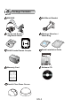
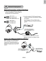
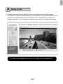
Quick Installation Guide
English
繁中
簡中
日本語
Français
Español
SD8362E
20x Zoom‧2MP‧Full HD
P/N: 625014300G Ver.1.0
Copyright c 2011 VIVOTEK INC. All rights reserved.
Deutsch
Português
Italiano
Türkçe
Polski
Русский
Česky
Svenska
English
Warning Before Installation
Power off the Network Camera as
soon as smoke or unusual odors are
detected.
Refer to your user’s manual for the
operating temperature.
Contact your distributor in the
event of occurrence.
Do not disassemble the Network
Camera.
Do not touch the Network Camera
during a lightning storm.
Do not insert sharp or tiny objects
into the Network Camera.
Do not drop the Network Camera.
Do not manually pan and tilt the
Network Camera when the power is
on.
EN-1
1
Package Contents
SD8362E
Wall Mount Bracket
D
GN
2DO
1DO
+
DO
GND
D13
D12
D11
Moisture Absorber /
Metal Ring
O-ring and Screws /
Alignment Sticker
Silica gel
Silica gel
RJ45 Female/Female Coupler
Quick Installation Guide
Quick Installation Guide
English
繁中
簡中
日本語
Français
Español
Deutsch
Português
Italiano
Türkçe
Polski
Русский
Česky
Svenska
SD8362E
20x Zoom•2MP•Full HD
Warranty Card
Software CD
Black & Clear Dome Covers
EN-2
English
2
Physical Description
Inner View
SD/SDHC Card Slot
Status LED
Reset Button
Lens
Outer View
GND
DO2DO1DO+
D
GN
2DO
1DO
+
DO
GND
D13
D12
D11
GND
D13
D12
D11
General I/O
Terminal Block
Ethernet 10/100
RJ45 Plug
Audio Out (green)
Microphone In (pink)
Power Cord Socket (black)
Ground
EN-3
3
Hardware Installation
Mounting the Network Camera
1. Attach the alignment sticker to the wall.
2. Drill four pilot holes into the wall.
3. Attach the black cover to the Network Camera using the supplied four black
screws.
4. Stick the supplied two pieces of moisture absorber symmetrically to the inner
side of the dome cover. Then place the metal ring into the dome cover to fix the
moisture absorber.
5. Fix the dome cover to the Network Camera and secure it by rotating it clockwise.
6. Loosen the three screws on the front opening of the wall mount bracket.
7. Place the O-ring on the front opening of the wall mount bracket.
8. Feed the cables through the front opening of the wall mount bracket and pull them
from wall outlet.
9. Attach the Network Camera to the wall mount bracket by tightening the three
screws on the front opening of the wall mount bracket.
10. Fasten the wall mount bracket to the wall.
10
1
7
8
2
3
5
6
4
Silica gel
Silica gel
EN-4
9
English
4
Network Deployment
General Connection (without PoE Plus)
1. If you have external devices such as
sensors and alarms, connect them to
the general I/O terminal block.
GND
DO2DO1DO+
GND
DI3
DI2
DI1
GND: Ground
DO2: Digital Output 2
DO1: Digital Output 1
DO+: Digital Outupt (DC12V)
GND: Ground
DI3: Digital Input 3
DI2: Digital Input 2
DI1: Digital Input 1
2. Use the supplied RJ45 female/female
coupler to connect the Network Camera
to a switch.
Use Category 5 Cross Cable when
Network Camera is directly connected
to PC.
POWER
COLLISION
1
2
3
4
5
LINK
RECEIVE
PARTITION
D
GN 2DO 1DO +
DO
GND
D13
D12
D11
AC 24V 3.5A Adapter
(optional)
3. Connect the power cable from the
Network Camera to a power outlet.
Power over Ethernet (PoE Plus 802.3at)
When using a non-PoE switch
Use a PoE Plus power injector
(optional) to connect between the
Network Camera and a non-PoE
switch.
D
GN
2DO
1DO
+
DO
GND
D13
D12
D11
PoE Plus Power Injector
(optional)
Non-PoE Switch
POWER
EN-5
COLLISION
1
2
3
4
5
LINK
RECEIVE
PARTITION
5
Assigning IP Address
1. Install "Installation Wizard 2" from the Software Utility directory on the software CD.
2. The program will conduct an analysis of your network environment. After your network
is analyzed, please click on the "Next" button to continue the program.
IW2
Installation
Wizard 2
3. The program will search for VIVOTEK Video Receivers, Video Servers, and Network
Cameras on the same LAN.
4. After a brief search, the main installer window will pop up. Double-click on the MAC
address that matches the one printed on the camera label or the S/N number on the
package box label to open a browser management session with the Network Camera.
Network Camera
Model No: SD8362E
MAC:0002D1730202
00-02-D1-73-02-02
192.168.3.143
R o HS
This device complies with part 15 of the FCC rules. Operation is subject to the following two conditions:
(1)This device may not cause harmful interference, and
(2) this device must accept any interference received, including interference that may cause undesired operation.
Pat. 6,930,709
0002D1730202
Made in Taiwan
EN-6
SD8362E
English
6
Ready to Use
1. A browser session with the Network Camera should prompt as shown below.
2. You should be able to see live video from your camera. You may also install the 32channel recording software from the software CD in a deployment consisting of
multiple cameras. For its installation details, please refer to its related documents.
For further setup, please refer to the user's manual on the software CD.
EN-7
Quick Installation Guide
English
繁中
簡中
日本語
Français
Español
SD8362E
20x Zoom‧2MP‧Full HD
P/N: 625014300G Ver.1.0
Copyright c 2011 VIVOTEK INC. All rights reserved.
Deutsch
Português
Italiano
Türkçe
Polski
Русский
Česky
Svenska