1
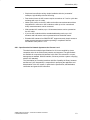
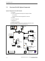
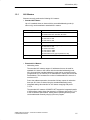
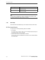
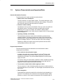
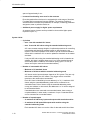
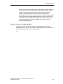
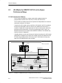
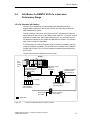
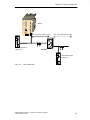
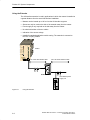
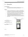
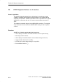
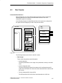
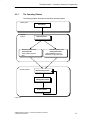
Preface, Contents
AS-Interface (AS-i)
SIMATIC NET
The AS-i Master
AS-Interface – Introduction and
Basic Information
Further AS-i System Components
The Master Mode – Commands, Sequence, Programming
1
2
3
4
Manual
Appendix
AS-Interface
Industrial Ethernet
PROFIBUS
AS-Interface
12/99
C79000-G8976-C089
Release 03
References
A
Glossary
B
SIMATIC NET – Support and Training
C
Safety Guidelines
This manual contains notices which you should observe to ensure your own personal safety, as well as to
protect the product and connected equipment. These notices are highlighted in the manual by a warning
triangle and are marked as follows according to the level of danger:
!
!
!
Danger
indicates that death, severe personal injury or substantial property damage will result if proper precautions
are not taken.
Warning
indicates that death, severe personal injury or substantial property damage can result if proper precautions are not taken.
Caution
indicates that minor personal injury or property damage can result if proper precautions are not taken.
Note
draws your attention to particularly important information on the product, handling the
product, or to a particular part of the documentation.
Qualified Personnel
Only qualified personnel should be allowed to install and work on this equipment. Qualified persons are
defined as persons who are authorized to commission, to ground, and to tag circuits, equipment, and systems in accordance with established safety practices and standards.
Correct Usage
Note the following
!
Warning
This device and its components may only be used for the applications described in the catalog or the
technical description, and only in connection with devices or components from other manufacturers which
have been approved or recommended by Siemens.
This product can only function correctly and safely if it is transported, stored, set up, and installed
correctly, and operated and maintained as recommended.
Trademarks
SIMATICR, SIMATIC HMIR and SIMATIC NETR are registered trademarks of the SIEMENS AG.
Third parties using for their own purpose any other names in this document which refer to trademarks
might infringe upon the rights of the trademark owners.
Copyright E Siemens AG 19989All rights reserved
Disclaimer of Liability
The reproduction, transmission or use of this document or its
contents is not permitted without express written authority.
Offenders will be liable for damages. All rights, including rights
created by patent grant or registration of a utility model or design, are
reserved.
We have checked the contents of this manual for agreement with the
hardware and software described. Since deviations cannot be
precluded entirely, we cannot guarantee full agreement. However,
the data in this manual are reviewed regularly and any necessary
corrections included in subsequent editions. Suggestions for
improvement are welcomed.
Siemens AG
A&D
Geschaeftsgebiet Industrie–Automatisierung
Postfach 4848, D-90327 Nuernberg
Siemens Aktiengesellschaft
Technical data subject to change.
E Siemens AG 1999
C79000-G8976-C089
Preface
Purpose of the Manual
This manual contains basic information and an introduction to the AS-Interface
system concept and the corresponding system components.
You require this manual to understand the manuals that are shipped with the AS-i
system components, particularly with the AS-i master.
This release of the manual contains supplementary information relating to the
expansion of the AS-i master specification and the extended SIMATIC NET
product range.
This involves the following aspects:
S
The extended addressing mode allows the addressing of up to 62 AS-i slaves.
S
Integrated, simple analog value transfer.
The AS-Interface is an open international standard
The AS-Interface is the open international standard EN 50 295. Leading
manufacturers of actuators and sensors support the AS-Interface world-wide. The
electrical and mechanical specifications are available for interested companies.
Further Support – Who to Contact
If you have technical questions about using the product described here, please
contact your local Siemens representative.
You will find further information in the appendix in “Support and Training”.
SIMATIC NET AS-Interface – Introduction and Basic Information
C79000-G8976-C089/03
i
Preface
Other Documentation
You should also read the product information bulletins supplied with the AS-i
components from SIMATIC NET and the manuals that can be ordered additionally.
Refer also to the references in the appendix of this manual.
-
ii
SIMATIC NET AS-Interface – Introduction and Basic Information
C79000-G8976-C089/03
Contents
1
2
3
4
AS-Interface (AS-i) . . . . . . . . . . . . . . . . . . . . . . . . . . . . . . . . . . . . . . . . . . . . . . . . . . . . . .
1-1
1.1
Area of Application . . . . . . . . . . . . . . . . . . . . . . . . . . . . . . . . . . . . . . . . . . . . . .
1-2
1.2
1.2.1
1.2.2
1.2.3
Overview of the AS-i System Components . . . . . . . . . . . . . . . . . . . . . . . . . .
AS-i Masters . . . . . . . . . . . . . . . . . . . . . . . . . . . . . . . . . . . . . . . . . . . . . . . . . . . .
AS-i Slaves . . . . . . . . . . . . . . . . . . . . . . . . . . . . . . . . . . . . . . . . . . . . . . . . . . . . .
Further AS-i System Components . . . . . . . . . . . . . . . . . . . . . . . . . . . . . . . . .
1-4
1-5
1-6
1-8
1.3
System Characteristics and Important Data . . . . . . . . . . . . . . . . . . . . . . . . .
1-9
The AS-i Masters . . . . . . . . . . . . . . . . . . . . . . . . . . . . . . . . . . . . . . . . . . . . . . . . . . . . . . .
2-1
2.1
AS-i Masters for the SIMATIC S7-200 . . . . . . . . . . . . . . . . . . . . . . . . . . . . . .
2-2
2.2
AS-i Masters for the SIMATIC S7-300 . . . . . . . . . . . . . . . . . . . . . . . . . . . . . .
2-4
2.3
AS-i Master for SIMATIC S5 PLCs in the Higher Performance Range . .
2-6
2.4
AS-i Master for SIMATIC S5 PLCs in the Lower Performance Range . . .
2-7
2.5
AS-i Gateways . . . . . . . . . . . . . . . . . . . . . . . . . . . . . . . . . . . . . . . . . . . . . . . . . .
2-8
2.6
AS-i Master for ET 200X . . . . . . . . . . . . . . . . . . . . . . . . . . . . . . . . . . . . . . . . .
2-10
2.7
AS-i Master for PC-AT . . . . . . . . . . . . . . . . . . . . . . . . . . . . . . . . . . . . . . . . . . .
2-11
Further AS-i System Components . . . . . . . . . . . . . . . . . . . . . . . . . . . . . . . . . . . . . . .
3-1
3.1
The AS-i Cable . . . . . . . . . . . . . . . . . . . . . . . . . . . . . . . . . . . . . . . . . . . . . . . . .
3-2
3.2
AS-i Modules: Blocks of the AS-i Slaves . . . . . . . . . . . . . . . . . . . . . . . . . . . .
3-3
3.3
Installing an AS-i Module . . . . . . . . . . . . . . . . . . . . . . . . . . . . . . . . . . . . . . . . .
3-5
3.4
AS-Interface Repeater / Extender . . . . . . . . . . . . . . . . . . . . . . . . . . . . . . . . .
3-6
3.5
Addressing Unit . . . . . . . . . . . . . . . . . . . . . . . . . . . . . . . . . . . . . . . . . . . . . . . . .
3-9
3.6
SCOPE Diagnostic Software for AS-Interface . . . . . . . . . . . . . . . . . . . . . . .
3-10
The Master Mode – Commands, Sequence, Programming . . . . . . . . . . . . . . . . .
4-1
4.1
4.1.1
4.1.2
Master-Slave Principle . . . . . . . . . . . . . . . . . . . . . . . . . . . . . . . . . . . . . . . . . . .
Tasks and Functions of the AS-i Master . . . . . . . . . . . . . . . . . . . . . . . . . . . .
How an AS-i Slave Functions . . . . . . . . . . . . . . . . . . . . . . . . . . . . . . . . . . . . .
4-2
4-3
4-4
4.2
4.2.1
4.2.2
4.2.3
Data Transfer . . . . . . . . . . . . . . . . . . . . . . . . . . . . . . . . . . . . . . . . . . . . . . . . . . .
The Operating Phases . . . . . . . . . . . . . . . . . . . . . . . . . . . . . . . . . . . . . . . . . . .
Interface Functions . . . . . . . . . . . . . . . . . . . . . . . . . . . . . . . . . . . . . . . . . . . . . .
Operating Extended AS-i Slaves with Standard AS-i Masters . . . . . . . . . .
4-5
4-7
4-10
4-11
SIMATIC NET AS-Interface – Introduction and Basic Information
C79000-G8976-C089/03
iii
Contents
A
References . . . . . . . . . . . . . . . . . . . . . . . . . . . . . . . . . . . . . . . . . . . . . . . . . . . . . . . . . . . . .
A-1
B
Glossary . . . . . . . . . . . . . . . . . . . . . . . . . . . . . . . . . . . . . . . . . . . . . . . . . . . . . . . . . . . . . . .
B-1
C
SIMATIC NET – Support and Training . . . . . . . . . . . . . . . . . . . . . . . . . . . . . . . . . . . .
C-1
Index
-
iv
SIMATIC NET AS-Interface – Introduction and Basic Information
C79000-G8976-C089/03
AS-Interface (AS-i)
1
This chapter deals with the following topics:
S
The range of applications that can be covered by the AS-Interface
S
Which system components are available on the AS-Interface
S
The system properties of the AS-Interface
SIMATIC NET AS-Interface – Introduction and Basic Information
C79000-G8976-C089/03
1-1
AS-Interface (AS-i)
1.1
Area of Application
AS-i Cable Replaces “Cable Harnesses”
The Actuator/Sensor Interface or AS-Interface, normally abbreviated to AS-i, is a
connection system for the lowest process level in automation systems. The cable
harnesses previously found at this level are replaced by a single electrical cable,
the AS-i cable. Using the AS-i cable and the AS-i master, the simplest binary
sensors and actuators can be connected to the control devices at the field level via
AS-i modules.
AS-Interface in SIMATIC
AS-Interface is the SIMATIC product name for the AS-i technology.
Under the name AS-interface, Siemens produces master interface modules for
industrial PCs and programmable controllers. The range of available master
interface modules is being permanently extended. Up-to-date information can be
obtained from your local Siemens office.
The following diagram illustrates the position of AS-i within the automation system.
AS-Interface
Management level
Industrial Ethernet
Cell level
Field level
PROFIBUS
Process
level
AS-Interface
Figure 1-1
The AS-interface is distinguished by several main characteristics:
S
1-2
AS-interface is optimized for connecting binary sensors and actuators. The AS-i
cable is used both for data exchange between the sensors/actuators (AS-i
slaves) and the AS-i master as well as for power supply to the sensors /
actuators.
SIMATIC NET AS-Interface – Introduction and Basic Information
C79000-G8976-C089/03
AS-Interface (AS-i)
S
Simple and cost-effective wiring: simple installation with the “penetration”
technique, high flexibility with tree-like wiring.
S
Fast reaction times: the AS-i master requires a maximum of 5 ms for cyclic data
exchange with up to 31 nodes.
S
Nodes (AS-i slaves) on the AS-i cable can be either sensors/actuators with an
integrated AS-i connector or AS-i modules to which up to four conventional
binary sensors/actuators can be connected.
S
With standard AS-i modules, up to 124 actuators/sensors can be operated on
the AS-i cable.
S
If you use AS-i modules with the extended addressing mode, up to 186
actuators and 248 sensors can be operated with one extended master.
S
Extended AS-i masters from SIMATIC NET support extremely simple access to
analog sensors/actuators or modules operating in compliance with the
AS-Interface slave profile 7.3/7.4.
AS-i - Open Standard for Network Systems at the Process Level
The electrical and mechanical specifications for AS-i were compiled by eleven
companies active in the field of binary sensors and actuators. The specifications
are available for companies with interests in this field. This makes AS-i an open,
heterogeneous standard. With AS-interface, Siemens provides a system complying
with the AS-i standard.
The “Association for Promoting Interfaces with Bus Capability for Binary Actuators
and Sensors” (AS-i Association) is responsible for promoting the application and
dissemination of the AS-i system; in particular the specification, standardization,
certification and general user information.
SIMATIC NET AS-Interface – Introduction and Basic Information
C79000-G8976-C089/03
1-3
AS-Interface (AS-i)
1.2
Overview of the AS-i System Components
System Components in the AS-i Network
S
AS-i master
S
AS-i slaves, distinguished according to their design as follows:
– AS-i modules
– Sensors/actuators with an integrated AS-i connection
S
AS-i cable
S
AS-i power supply unit
S
Addressing unit
S
SCOPE for AS-Interface
The following diagram illustrates how the described components can be
interconnected. The tree structure is particularly clear.
AS-i master
AS-i power
supply unit
SIMATIC, e.g. CP 343-2
(slave 2)
Sonar BERO with an
integrated AS-i connection
Branch
Branch M12
Inductive BERO
with an integrated
AS-i connection
(slave 1)
A slave
AS-i modules
with extended
addressing mode
Button
B slave
ÑÑÑ
4I module for
connecting standard
sensors
(slave 3)
Solenoid valve
Indicator
lamp
Standard sensor
e.g. ind. BERO
4O module with relay contacts
for connecting standard
actuators
(slave 4)
Standard transmitter
e.g. position switch
Shaped AS-i cable
Round AS-i cable
24 V DC
contactor
Standard 24V DC power
supply unit for external
supply to standard
actuators
Figure 1-2
1-4
SIMATIC NET AS-Interface – Introduction and Basic Information
C79000-G8976-C089/03
AS-Interface (AS-i)
1.2.1
AS-i Masters
Siemens currently produces the following AS-i masters:
S
Standard AS-i Master
Up to 31 standard slaves or slaves with the extended addressing mode (A
slaves only) can be attached to standard AS-i masters.
for System
Standard AS-i master
SIMATIC S5 PLC:
CP 2433 for S5-90U, S5-95U, S5-100U,
CP 2430 for S5-115U, S5-135U, S5-155U
SIMATIC S7 PLC:
CP 242-2 for S7-200
CP 242-8 for S7-200
CP 342-2 for S7-300
SIMATIC C7:
C7-621 ASi
Distributed I/Os:
DP/AS-Interface Link 20 (type of protection IP 20)
CP 242-8 for S7-200
CP 2433 for ET 200U
CP 342-2 for ET 200M
CP 142-2 for ET 200X
DP/AS-Interface Link (type of protection IP 65)
IBM-compatible PCs:
CP 2413 for PC-AT
S
Extended AS-i Masters
– Addressing mode
The extended AS-i masters support 31 addresses that can be used for
standard AS-i slaves or AS-i slaves with the extended addressing mode.
AS-i slaves with the extended addressing mode can be connected in pairs
(programmed as A or B slaves) to an extended AS-i master and can use the
same address. This increases the number of addressable AS-i slaves to a
maximum of 62.
Due to the address expansion, the number of binary outputs is reduced to
three per AS-i slave on slaves using the extended addressing mode.
– Integrated analog value transfer for AS-i slaves complying with profile
7.3/7.4
The extended AS-i masters of SIMATIC NET support the integrated transfer
of AS-Interface analog slaves that operate in compliance with profile 7.3/7.4
of the AS-Interface specification. Analog slaves operating with this profile
can be addressed extremely simply by the user program.
SIMATIC NET AS-Interface – Introduction and Basic Information
C79000-G8976-C089/03
1-5
AS-Interface (AS-i)
for System
Extended AS-i masters
SIMATIC S7 PLC:
CP 243-2 for S7-200
CP 343-2 for S7-300
Distributed I/Os:
DP/AS-Interface Link 20E (type of protection IP 20)
CP 343-2 for ET200M
Note
Since the range of available AS-i masters is constantly being extended, consult
your Siemens representative about further AS-i masters.
1.2.2
AS-i Slaves
All the nodes that can be addressed by an AS-i master are known as AS-i slaves.
AS-i Slave Assembly System
AS-i slaves with the following assembly systems are available:
S
AS-i modules
AS-i modules are AS-i slaves to which up to 4 conventional sensors and up to 4
conventional actuators can be connected.
S
Sensors/actuators with an integrated AS-i connection
Sensors/actuators with an integrated AS-i connection can be connected directly
to the AS-Interface.
1-6
SIMATIC NET AS-Interface – Introduction and Basic Information
C79000-G8976-C089/03
AS-Interface (AS-i)
Addressing Mode
AS-i slaves are available with the following addressing modes:
S
Standard slaves
Standard slaves each occupy one address on the AS-Interface. Up to 31
standard slaves can be connected to the AS-Interface.
S
Slaves with the extended addressing mode (A/B slaves)
Slaves with the extended addressing mode can be operated in pairs at the
same address with an extended AS-i master. This doubles the number of
addressable AS-i slaves to 62.
One of these AS-i slaves must be programmed as an A slave using the
addressing unit and the other as a B slave. Due to the address expansion, the
number of binary outputs is reduced to three per AS-i slave.
A slaves can also be operated with a standard AS-i master (see also Section
4.2.3)
For more detailed information about these functions, refer to the AS-i master in
the previous section.
Analog Slaves
Analog slaves are special AS-i standard slaves that exchange analog values with
the AS-i master. Analog slaves are available with the following profiles:
S
Analog slaves complying with profile 7.1/7.2
Analog slaves complying with profile 7.1/7.2 require special program sections in
the user program (drivers, function blocks) that execute the sequential transfer
of analog data.
S
Analog slaves complying with profile 7.3/7.4
Analog slaves complying with profile 7.3/7.4 are intended for operation with
extended AS-i masters. The extended AS-i masters handle the exchange of
analog data with these slaves automatically. No special drivers or function
blocks are required in the user program.
SIMATIC NET AS-Interface – Introduction and Basic Information
C79000-G8976-C089/03
1-7
AS-Interface (AS-i)
1.2.3
Further AS-i System Components
AS-i Cable
The AS-i cable, designed as an unshielded 2-wire cable, transfers signals and
provides the power supply for the sensors and actuators connected using AS-i
modules.
Networking is not restricted to one type of cable. If necessary, appropriate modules
or “T pieces” can be used to change to a simple 2-wire cable.
Note
If you change to a simple 2-wire cable, keep in mind the technical restrictions such
as cable cross section, voltage drop, and cable length as described in the AS-i
specification (see /1/ and /2/).
AS-i Power Supply Unit
The AS-i power supply unit supplies power for the AS-i nodes connected to the
AS-i cable. For actuators with particularly high power requirements, the connection
of an additional load power supply may be necessary (for example using special
application modules).
Addressing Unit
The addressing unit allows simple programming of AS-i slave addresses.
SCOPE for AS-Interface
SCOPE AS-interface (previously SCOPE S1) is a monitoring program for
WINDOWS which can record and evaluate the data exchange in AS-i networks
during the commissioning phase and during operation. SCOPE AS-interface can
be operated on a PC under WINDOWS in conjunction with the AS-i master
communications processor CP 2413.
1-8
SIMATIC NET AS-Interface – Introduction and Basic Information
C79000-G8976-C089/03
AS-Interface (AS-i)
1.3
System Characteristics and Important Data
How the AS-Interface Functions
The AS-Interface/AS-i system operates as outlined below:
S
Master-slave access techniques
The AS-i interface is a “single master system”. This means that there is only
one master per AS-i network which controls the data exchange. This polls all
AS-i slaves one after the other and waits for a response.
S
Electronic address setting
The address of an AS-i slave is its identifier. This only occurs once within an
AS-Interface system. The setting can either be made using a special
addressing unit or by an AS-i master. The address is always stored
permanently on the AS-i slave. When they are supplied, the AS-i slaves always
have the address “0”.
S
Operating reliability and flexibility
The transmission technique used (current modulation) guarantees high
operating reliability. The master monitors the voltage on the cable and the
transferred data. It detects transmission errors and the failure of slaves and
sends a message to the PLC. The user can then react to this message.
Replacing or adding AS-i slaves during normal operation does not affect
communication with other AS-i slaves.
Physical Characteristics
The most important physical characteristics of the AS-Interface and its
components are as follows:
S
2-wire cable for data and power supply
A simple 2-wire cable with a cross section of 2 x 1.5 mm2 can be used.
Shielding or twisting is not necessary. Both the data and the power are
transferred on this cable. The power available depends on the AS-i power
supply unit used.
For optimum wiring, the mechanically coded AS-i cable is available preventing
the connections being reversed and making simple contact with the AS-i
application modules using the penetration technique.
S
Tree structure network with a cable length up to 100 m
The “tree structure” of the AS-Interface allows any point on a cable section to
be used as the start of a new branch. The total length of all subsections can be
up to 100 m.
S
Direct integration
Practically all the electronics required for a slave have been integrated on a
special IC. This allows the AS-i connector to be integrated directly in binary
actuators or sensors. All the required components can be installed within a
SIMATIC NET AS-Interface – Introduction and Basic Information
C79000-G8976-C089/03
1-9
AS-Interface (AS-i)
space of approximately 2 cm3.
S
Increased functionality, more uses for the customer
Direct integration allows devices to be equipped with a wide range of functions.
Four data and four parameter lines are available. The resulting “intelligent”
actuators/sensors increase the possibilities, for example, monitoring, parameter
assignment, wear or pollution checks etc.
S
Additional power supply for higher power requirements
An external source of power can be provided for slaves with a higher power
requirement (see /1/).
System Limits
S
Cycle time
– max. 5 ms with standard AS-i slaves
– max. 10 ms with AS-i slaves using the extended addressing mode
AS-i uses constant message lengths. Complicated procedures for controlling
transmission and identifying message lengths or data formats are not
required. This makes it possible for a master to poll all connected standard
slaves within a maximum of 5 ms and to update the data both on the master
and slave.
If only one AS-i slave using the extended addressing mode is located at an
address, this slave is polled at least every 5 ms. If two extended slaves (A
and B slave) share an address, the maximum polling cycle is 10 ms. (B
slaves can only be connected to extended masters.)
S
Number of connectable AS-i slaves
– Maximum of 31 standard slaves
– Maximum of 62 slaves with the extended addressing mode
AS-i slaves are the input and output channels of AS-i system. They are only
active when called by the AS-i master. They trigger actions or transmit
reactions to the master when commanded.
Each AS-i slave is identified by its own address (1 to 31). A maximum of 62
slaves using the extended addressing mode can be connected to an
extended master. Pairs of slaves using the extended addressing mode
occupy one address; in other words, the addresses 1 to 31 can be assigned
to two extended slaves.
If standard slaves are connected to an extended master, these occupy a
complete address; in other words, a maximum of up to 31 standard slaves
can be connected to an extended master.
S
Number of inputs/outputs
– A maximum of 248 binary inputs and outputs with standard modules
– A maximum of 248 inputs/186 outputs with modules using the
extended addressing mode
Each standard AS-i slave can receive 4 bits of data and send 4 bits of data.
1-10
SIMATIC NET AS-Interface – Introduction and Basic Information
C79000-G8976-C089/03
AS-Interface (AS-i)
Special modules allow each of these bits to be used for a binary actuator or
a binary sensor. This means that an AS-i cable with standard AS-i slaves
can have a maximum of 248 binary attachments (124 inputs and 124
outputs). All typical actuators or sensors can be connected to the
AS-interface in this way. The modules are used as distributed inputs/outputs.
If modules with the extended addressing mode are used, a maximum of 3
inputs and 3 outputs is available per module; in other words a maximum of
248 inputs and 186 outputs can be operated with modules using the
extended addressing mode.
Range of Functions of the Master Modules
The functions of the AS-i master modules are stipulated in the AS-i master
specification (see /1/ and /2/). An overview of these functions can be found in the
PICS in the appendix of the master module manual.
-
SIMATIC NET AS-Interface – Introduction and Basic Information
C79000-G8976-C089/03
1-11
AS-Interface (AS-i)
1-12
SIMATIC NET AS-Interface – Introduction and Basic Information
C79000-G8976-C089/03
The AS-i Masters
2
AS-Interface is a single-master system. For SIMATIC systems, there are
communications processors (CPs) that control the process or field communication
as the AS-i masters.
These also include gateways that operate like an AS-i master and allow access to
the actuators and sensors, for example, of PROFIBUS DP.
This chapter introduces you to these AS-i system components. For more detailed
information on handling, configuring, and programming, refer to the manual of the
relevant device.
SIMATIC NET AS-Interface – Introduction and Basic Information
C79000-G8976-C089/03
2-1
The AS-i Masters
2.1
AS-i Masters for the SIMATIC S7-200
CP 242-2 (Standard AS-i Master)
The CP 242-2 module allows the connection of an AS-i chain to the S7-200
programmable logic controller. The CP 242-2 provides the complete functionality of
the AS-i master specification for standard AS-i masters (profile M1).
S7-200 CPU
CPU 212
SIEMENS
SIMATIC
S7–200
AS-i master
CP 242-2
Passive module
(without integrated
AS-i connection)
Active module
(with integrated
AS-i connection)
AS-i power supply
Actuator/sensor
(with integrated
AS-i connection)
AS-i cable
Branch
Figure 2-1
CP 243-2 (Extended AS-i Master)
The CP 243-2 module allows connection of an AS-i chain to the new S7-200 series
(CPU 222, CPU 224, etc.). The CP 243-2 is an extended master complying with
profile M1e; in other words, it covers the complete functionality of the AS-i master
specification for extended AS-i masters.
2-2
SIMATIC NET AS-Interface – Introduction and Basic Information
C79000-G8976-C089/03
The AS-i Masters
CP 242-8 (Standard AS-i Master)
The CP 242-8 has not only the functions of the CP 242-2 but also a connection to
PROFIBUS DP (DP slave). This allows the cost-effective connection of an S7-200
to PROFIBUS DP and the AS-Interface at the same time.
Wider ranging network via PROFIBUS DP
S7-200 CPU
SIEMENS
SF
RUN
STOP
SIMATIC
S7–200
I 0.0
I 0.1
I 0.2
I 0.3
I 0.4
I 0.5
I 0.6
I 0.7
Q0.0
Q0.1
Q0.2
Q0.3
Q0.4
Q0.5
CP242-2
AS-Interface
Master
29 24 19 14
28 23 18 13
9 4
SF
8 3
APF
27 22 17 12
31 26 21 16 11
7 2
6 1
CER
AUP
30 25 20 15 10
5 0
CM
X2
34
6GK7
242-2AX00-0XA0
AS-i master/DP slave
CP 242–8
Passive module
(without integrated
AS-i connection)
Active module
(with integrated
AS-i connection)
AS-i power supply
Actuator/sensor
(with integrated
AS-i connection)
AS-i cable
Branch
Figure 2-2
SIMATIC NET AS-Interface – Introduction and Basic Information
C79000-G8976-C089/03
2-3
The AS-i Masters
2.2
AS-i Masters for the SIMATIC S7-300
CP 342-2 (Standard AS-i Master)
The CP 342-2 is available as the standard AS-i master module for controllers of
the S7-300 range and for the ET 200M distributed I/O system.
The CP 342-2 occupies 16 input and 16 output bytes in the analog area of the
controller via which the input data of the slaves can be read and the output data of
the slaves can be set.
When using an FC, in addition to the I/O data exchange, it is also possible to
execute master calls from within the control program. The FC is supplied on a
diskette along with the manual for the CP 342-2.
CP 342-2 / 343-2
S7-300
Active AS-i application module
(with slave ASIC)
Passive AS-i application module
(without integrated
AS-i connection)
AS-i power
supply unit
AS-i cable
(4 x slave)
Binary sensors and actuators
(with integrated
AS-i connection)
= Slave ASIC
Binary sensors and actuators
(without integrated AS-i connection)
Active or passive
AS-i application module
Branch of the
AS-i cable
Actuator or sensor
with direct connection
Figure 2-3
2-4
SIMATIC NET AS-Interface – Introduction and Basic Information
C79000-G8976-C089/03
The AS-i Masters
CP 343-2 (Extended AS-i Master)
The CP 343-2 is an extended AS-i master for S7-300 series controllers and the ET
200 M distributed I/O system.
The CP 343-2 occupies 16 input and 16 output bytes in the analog area of the
controller via which the AS-i standard slaves and AS-i A slaves can be addressed.
AS-i B slaves have an additional I/O area that is accessible using SFCs.
When using an FC, in addition to the I/O data exchange, it is also possible to
execute master calls from within the control program. The FC is supplied on a
diskette along with the manual for the CP 343-2.
SIMATIC NET AS-Interface – Introduction and Basic Information
C79000-G8976-C089/03
2-5
The AS-i Masters
2.3
AS-i Master for SIMATIC S5 PLCs in the Higher
Performance Range
CP 2430 (Standard AS-i Master)
The CP 2430 is available as a master module (AS-i standard master) for
programmable controllers of the S5-115U, S5-135U, S5-155U series.
The CP 2430 is a double master that can operate two independent AS-i networks
each with a maximum of 31 slaves.
If required, the AS-i master can be used like an I/O module in the PLC to address
the input and output data of the AS-i slaves. In the address area of the PLC, it
occupies 16 input and 16 output bytes per AS-i chain, in other words a total of 32
input bytes and 32 output bytes. In terms of programming the PLC, there is no
difference between an AS-i master and standard I/O modules. The software only
needs a minimum of adaptation.
If handling blocks are used, the full range of functions according to the AS-i master
specification is available. As an option, the I/O data can also be transferred to the
CP 2430 using handling blocks. In this case, the CP 2430 does not occupy any
space in the I/O address area of the controller.
SIMATIC NET Industrial Ethernet
or
CP 2430
SIMATIC NET PROFIBUS
Segment A
AS-i cable
Segment B
Active AS-Interface
application module
(with slave ASIC)
Passive AS-Interface application module
(without integrated
AS-i connection)
AS-i power
AS-i cable
(4 x slave)
supply unit
Binary sensors and actuators
Binary sensors and actuators
(with integrated
AS-i connection)
= slave ASIC
(without integrated AS-i connection)
Active or passive
AS-Interface user module
Branch of the
Actuator or sensor
AS-i cable
with direct
connection
Figure 2-4
2-6
Example of a SIMATIC S5 System Configuration with the CP 2430
SIMATIC NET AS-Interface – Introduction and Basic Information
C79000-G8976-C089/03
The AS-i Masters
2.4
AS-i Master for SIMATIC S5 PLCs in the Lower
Performance Range
CP 2433 (Standard AS-i Master)
The CP 2433 is available as a master module (AS-i standard master) for
programmable controllers of the S5-90U, S5-95U, S5-100U series and the ET
200U distributed I/O system.
The AS-i master is used like an I/O module in the PLC to address the input and
output data of the AS-i slaves. In the address area of the PLC, it occupies 16 input
bytes and 16 output bytes. When programming the PLC, the user does not see
any difference between an AS-i master and standard I/O modules. The software
only needs a minimum of adaptation.
If a function block is used, the complete range of functions according to the AS-i
master specification is available. This function block is available for the SIMATIC
S5-95U and S5-100U / CPU 103 and is supplied on diskette with the manual for
the CP 2433.
The CP 2433 occupies a double slot on the bus bar.
S5-95U
AS-i
power
supply
unit
CP 2433
Actuator or sensor
with direct
connection
Passive AS-i module
(without integrated
AS-i connection)
Active AS-i module
(with integrated
AS-i connection)
AS-i cable
(4 x slave)
Binary sensors and actuators
(with integrated
AS-i connection)
Branch of the
AS-i cable
Binary sensors and actuators
(without integrated
AS-i connection)
Active or passive
AS-i module
= Slave ASIC
Figure 2-5
Example of a SIMATIC S5 PLC with the CP 2433
SIMATIC NET AS-Interface – Introduction and Basic Information
C79000-G8976-C089/03
2-7
The AS-i Masters
2.5
AS-i Gateways
DP / AS-i Gateway
Even when using the PROFIBUS DP distributed I/Os, the use of AS-Interface can
have advantages. The networking of the process peripherals can be extended
beyond PROFIBUS to include the actuators/sensors.
The following devices can be used as gateways to PROFIBUS:
2-8
S
DP/AS-Interface Link 20 (a link designed in compliance with IP 20 for
interfacing AS-Interface to PROFIBUS DP)
S
DP/AS-Interface Link 20E (link designed in compliance with IP 20 with extended
AS-i master functionality for interfacing AS-Interface to PROFIBUS-DP)
S
CP 242-8 (simultaneous connection of an S7-200 to PROFIBUS DP and
AS-Interface)
S
CP 142-2 in the ET 200X
S
CP 342-2 in the ET 200M
S
CP 343-2 in the ET 200M (extended master)
S
CP 2433 in the ET 200U
S
S5-95U PLC with PROFIBUS interface and CP 2433
S
S7-300 / CPU 315-2 DP with CP 342-2 or DP343-2
S
DP/AS-Interface Link (link designed in compliance with IP 65 for connecting the
AS-Interface to PROFIBUS DP)
SIMATIC NET AS-Interface – Introduction and Basic Information
C79000-G8976-C089/03
The AS-i Masters
Wider ranging network via PROFIBUS DP
DP/AS-Interface Link 20 E
ADR
BF
29 24 19 14 9 4
28 23 18 13 8 3
DIA
SF
DP-AS-Interface
Link20
APF
27 22 17 12
7 2
31 26 21 16 11
6 1
CER
AUP
30 25 20 15 10
5 0
CM
X2
34
6GK714152AA0
Passive module
(without integrated
AS-i connection)
Active module
(with integrated
AS-i connection)
AS-i power supply
Actuator/sensor
(with integrated
AS-i connection)
AS-i cable
Figure 2-6
AS-i distributor
Example of a System Configuration with the DP/AS-Interface Link 20
SIMATIC NET AS-Interface – Introduction and Basic Information
C79000-G8976-C089/03
2-9
The AS-i Masters
2.6
AS-i Master for ET 200X
CP 142-2 (Standard AS-i Master)
The CP 142-2 module (AS-i standard master) can be operated in the ET 200X
distributed I/O system. It allows the connection of an AS-i chain to the I/O device.
The special feature of the ET 200X distributed I/O system is its rugged
construction complying with IP 65, IP 66 and IP 67.
PROFIBUS-DP master
PROFIBUS
PROFIBUS
CP 142-2
ET 200 X
Round
cable
Active AS-i application module
(with integrated AS-i connection)
Passive AS-i application module
(without integrated
AS-i connection)
AS-i cable
AS-i power
supply unit
(4 x slave)
Binary sensors
and actuators
(with slave ASIC)
= slave ASIC
Figure 2-7
2-10
Binary sensors and actuators
(without slave ASIC)
Active or passive AS-i
application module
Branch of the
AS-i cable
Actuator or sensor with
direct connection
Example of an ET 200X with CP 142-2
SIMATIC NET AS-Interface – Introduction and Basic Information
C79000-G8976-C089/03
The AS-i Masters
2.7
AS-i Master for PC-AT
CP 2413 (Standard AS-i Master)
The CP 2413 (AS-i standard master) allows the attachment of AS-Interface to
PCs.
The hardware of the AS-i master is implemented as a short PC-AT card. Up to four
AS-i master CPs can be operated at the same time in one PC. This means that the
Siemens AS-i PC master is also suitable for complex control tasks. The firmware
running on the PC master is loaded when the host is started up.
An operating and demonstration program is available which provides the current
status of the slaves on the cable and permits simple operation of the slaves. This
program can also be used for diagnostic purposes; it also allows the programming
of the addresses of AS-i slaves.
Since not only the AS-i master card can be operated in a PC, but also PC
interfaces for the Industrial Ethernet and PROFIBUS bus at the same time, the
data supplied by the AS-i slaves can also be made available to other stations in the
network.
PROFIBUS or
Industrial Ethernet
AS-i power
supply unit
PC-AT
CP 2413
Actuator or sensor
with direct connection
Active AS-i module
(without integrated
AS-i connection)
Active AS-i module
(with integrated
AS-i connection)
AS-i cable
(4 x slave)
Binary sensors and actuators
without slave ASIC
Binary sensors and actuators
with slave ASIC
Active or passive AS-i
module
= Slave ASIC
Branch of the
AS-i cable
Figure 2-8
Example of a System Configuration with PC-AT and CP 2413
SIMATIC NET AS-Interface – Introduction and Basic Information
C79000-G8976-C089/03
2-11
The AS-i Masters
Library for Integrating the AS-i Functions
There are masters and libraries for C and Visual Basic applications for the master
under MS-DOS and Windows. These functions are described in the “CP 2413 AS-i
Master Module” manual.
-
2-12
SIMATIC NET AS-Interface – Introduction and Basic Information
C79000-G8976-C089/03
Further AS-i System Components
3
As well as the AS-i masters described in this manual, the components of the AS-i
transmission system and the AS-i slaves are also required on the AS-Interface.
The following sections provide an overview of the basic characteristics and
interaction of these components.
Due to the continuing development of new AS-i system components, a complete
presentation of all the currently available components is not possible. Refer to the
available system catalogs and ask your Siemens office for more information.
SIMATIC NET AS-Interface – Introduction and Basic Information
C79000-G8976-C089/03
3-1
Further AS-i System Components
3.1
The AS-i Cable
Design and Advantages
The AS-i cable (shaped cable) allows simple and fast installation of an AS-i
system. The AS-i cable is a rubberized 2-wire cable (2 x 1.5 mm2). The profile
section prevents stations being connected with incorrect polarity.
The AS-i cable is contacted using the penetration technique. Contact blades
penetrate the rubber jacket and make contact with the two wires. This
guarantees a low contact resistance and
10 mm
ensures a reliable data connection. The cable
does not need to be cut, have its insulation
removed or be screwed down. For this type of
4 mm
connection, there are coupling modules
6,5 mm
designed for the penetration technique.
The jacket of the AS-i cable is rubber. If modules need to be moved after they
have been connected to the AS-i cable this is possible without causing any
problems. The AS-i cable is “self-healing”. This means that the holes made by the
contact blades in the rubber jacket of the cable close themselves and revert to the
type of protection IP67. When the cable is installed in an AS-i module, the cable
seals the openings. The type of protection IP67 is therefore achieved.
Use of Other 2-Wire Cables
Apart from the special AS-i cable, any 2-wire cable with a cross-section of 2 x 1.5
mm2 can be used. Shielding or twisting is not necessary. For the transition from
the special AS-i cable to a different cable (e.g. a standard round cable) there is a
special module available without integrated electronics (transition from the AS-i
cable to four M12 connectors and transition from the AS-i cable to one M12
connector).
3-2
SIMATIC NET AS-Interface – Introduction and Basic Information
C79000-G8976-C089/03
Further AS-i System Components
3.2
AS-i Modules: Blocks of the AS-i Slaves
Concept
Within the AS-i system, the AS-i modules can be compared with input and output
modules. Along with the actuators and sensors they make up the AS-i slaves and
connect the slaves to the AS-i master. The actuators/sensors are connected via
M12 connectors. The pinout corresponds to DIN IEC 947 5-2. The modules with
dimensions of approximately 45 x 45 x 80 mm are used locally on the machine
itself. They are connected via the AS-i cable and have the degree of protection
IP67.
Active and Passive Modules
The following modules must be distinguished:
S
The active AS-i module with integrated AS-i chip
Using this, conventional sensors and actuators can be connected. Every normal
actuator or sensor can therefore be networked via AS-i.
S
The passive AS-i module
This does not contain its own electronics and allows the connection of AS-i
sensors and actuators with integrated AS-i chips.
In keeping with the concept of the standard AS-i master and the extended AS-i
master (see Section 1.2), either AS-i chips with standard functions or with
extended functions are used.
The modules are designed so that a uniform electromechanical interface to the
AS-i cable can be created. This is achieved with the uniform lower section of the
module, which is therefore also known as a coupling module.
Specially constructed upper module sections, also known as application modules
are also available. The variations in the module components range from the simple
cover for branching the AS-i cable to application modules with integrated AS-i
chips for connecting up to four conventional sensors or actuators.
SIMATIC NET AS-Interface – Introduction and Basic Information
C79000-G8976-C089/03
3-3
Further AS-i System Components
Example:
The following diagram illustrates an active AS-i module for four connections.
Operating indicator of the
actuator/sensor
switching signal
Upper section
(application module)
Application module operating
indicator
M12 connector
for
actuator/sensor
lower section
(coupling module)
AS-i cable
Standard rail 35
mm
Figure 3-1
Note
Please ask your local sales office or distributor about other AS-i modules (for
example 4I/4O module).
3-4
SIMATIC NET AS-Interface – Introduction and Basic Information
C79000-G8976-C089/03
Further AS-i System Components
3.3
Installing an AS-i Module
The installation of an AS-i module on the AS-i cable is particularly simple using the
connection technique described. This is made clear by the following illustration:
Figure 3-2
1. The coupling module is screwed or clipped
onto a 35 mm standard rail. The coupling
module includes four stoppers. These are
used to close unused cable openings.
Figure 3-3
2. The AS-i cable is inserted. It locks into a
guide above the contact blades and is
secured mechanically. No electrical contact
is established. Two stoppers are inserted in
the unused cable opening.
Figure 3-4
3. By screwing down the application module,
the AS-i cable is pressed onto the contact
blades. They penetrate the conductors at
two points and guarantee a reliable
connection. After correct installation, the
module has the type of protection IP67.
SIMATIC NET AS-Interface – Introduction and Basic Information
C79000-G8976-C089/03
3-5
Further AS-i System Components
3.4
AS-Interface Repeater / Extender
Area of Application
The AS interface repeater and extender is intended for use in an actuator-sensor
interface environment.
The device is used to extend the maximum possible length of the AS-interface of
100 m. An existing 100 m segment can be extended by a maximum of two further
100 m segments.
Using the Repeater
The AS-interface repeater is used when slaves must be operated on all cable
segments. A separate AS-interface power supply unit is then required for each
AS-interface segment (before and after the repeater). The repeater has the
following features:
3-6
S
Extends the cable length to a maximum of 300m.
S
Slaves can be used on both sides of the repeater.
S
A power supply unit is required on both sides of the AS interface.
S
Electrical isolation of the two cables.
S
Separate indication of the correct voltage for each side.
S
Installation in standard application module casing.
SIMATIC NET AS-Interface – Introduction and Basic Information
C79000-G8976-C089/03
Further AS-i System Components
ACTIVESLAVES
CP FAULT
RUN
S1 POWER FAIL
30
20
10
Master
CONFIGERROR
AUTOPROG
CONFIGMODE
SETCONFIG
CHANGEMODE
CP 2433
SINICS1
6GK1243–3SA00
1 2 34 5 6
S
II
M
I
N
9
8
7
6
5
4
3
2
1
0
7 9
+
8 10
max. 100 m AS-Interface cable
max. 100 m AS-Interface cable
S
POW
IRSUPPLY
ASI+
ASI–
Schirm
123456
L1
N
Schirm
ASI
+
ASI
–
AS-Interface power
supply unit
Repeater
S
II
M
I
N
S
POW
IRSUPPLY
ASI+
ASI–
Schirm
123456
L1
N
AS-Interface power
supply unit
Schirm
ASI
+
ASI
–
Figure 3-5
Using the Repeater
SIMATIC NET AS-Interface – Introduction and Basic Information
C79000-G8976-C089/03
3-7
Further AS-i System Components
Using the Extender
The AS-Interface extender is used in applications in which the master is installed at
a greater distance from the actual AS-Interface installation:
S
Masters can be located up to 100 m from the AS-interface segment.
S
Slaves can only be used on the side of the extender away from the master.
S
Power supply is only required on the side away from the master.
S
No electrical isolation of the two cables.
S
Indication of the correct voltage.
S
Installed in standard application module casing. The extender is mounted on
the FK-E coupling module.
ACTIVESLAVES
CP FAULT
RUN
S1 POWER FAIL
30
20
10
Master
CONFIGERROR
9
8
7
6
AUTOPROG
CONFIGMODE
SETCONFIG
CHANGEMODE
CP 2433
SINICS1
6GK1243–3SA00
1 2 34 5 6
5
4
3
2
1
0
7 9
+
8 10
max. 100m AS-Interface cable
max. 100 m AS-Interface cable
Extender
S
II
M
I
N
S
POW
IRSUPPLY
AS-Interface power
supply unit
ASI+
ASI–
Schirm
123456
L1
N
Schirm
ASI
+
ASI
–
Figure 3-6
3-8
Using the Extender
SIMATIC NET AS-Interface – Introduction and Basic Information
C79000-G8976-C089/03
Further AS-i System Components
3.5
Addressing Unit
Area of Application
Each slave on the AS-i requires an address. This address is saved on the slave.
You can program the address of a slave using the addressing unit.
Handling
To program a module (application module), it is plugged in to the special adapter
on the addressing unit. The stored address is displayed on the unit when you press
the ADR button. The new address is set using the arrow buttons. After pressing
the PRG button, the new address is saved on the application module (slave).
Addressing intelligent sensors/actuators is the same as with application modules.
The sensor/actuators are connected to the addressing unit via an M12 connector.
The addressing unit has an integrated M12 socket for this purpose.
The addressing unit is supplied by integrated batteries that can be charged using
an external power unit. When not in use, the unit switches off automatically after a
period of time.
Adapter
M12 socket
Address setter
extremely simple operation
Integrated adapter
suitable for application modules
Attachment also possible via M 12
(Sonar Bero)
Adresse+
Adresse–
Programmi eren
Lesen/I in
PRG
ADR
3RX9400–0AA00
Figure 3-7
SIMATIC NET AS-Interface – Introduction and Basic Information
C79000-G8976-C089/03
3-9
Further AS-i System Components
3.6
SCOPE Diagnostic Software for AS-Interface
Area of Application
The SCOPE diagnostic software for the AS-Interface is a monitoring program
capable of recording and evaluating the data exchange in AS-i networks during
installation and operation. SCOPE for AS-interface can be operated on a PC under
WINDOWS in conjunction with the AS-i master communications processor CP
2413.
The software is operated using the known WINDOWS conventions. The complete
range of functions can be found in the SIMATIC NET catalog /3/ and the product
manual.
Functions
SCOPE for AS-interface provides the following functions:
3-10
S
Online display of all master and slave user data in overview (data monitor);
S
Monitoring of slave activities
S
Online display of essential statistical values of data exchange on the bus;
S
Trigger and filter functions for recording;
S
Recording of the entire data exchange in a ring buffer;
S
Documentation functions. -
SIMATIC NET AS-Interface – Introduction and Basic Information
C79000-G8976-C089/03
The Master Mode – Commands, Sequence,
Programming
4
The tasks and functions of an AS-i master are described below.
This section is important for understanding the functions, modes and interfaces
available with the AS-i master modules. These functions and interfaces are
described in detail in the manuals of the individual CPs.
For further information refer to /1/
SIMATIC NET AS-Interface – Introduction and Basic Information
C79000-G8976-C089/03
4-1
The Master Mode – Commands, Sequence, Programming
4.1
Master-Slave Principle
How the AS-Interface Operates
The AS-Interface operates on the master-slave principle. This means that the AS-i
master connected to the AS-i cable controls the data exchange with the slaves via
the interface to the AS-i cable.
The following diagram illustrates the two interfaces of the AS-i master CP.
S
The process data and parameter assignment commands are transferred via the
interface between the master CPU and the master CP.
The user programs have suitable function calls and mechanisms available for
reading and writing via this interface.
S
Information is exchanged with the AS-i slaves via the interface between the
master CP and AS-i cable.
PLC / PC
AS-i slave
CPU
AS-i master
CP
I/O
User
program
Interface to the user
program
Configuration
Address
Parameters
AS-i cable
Figure 4-1
4-2
SIMATIC NET AS-Interface – Introduction and Basic Information
C79000-G8976-C089/03
The Master Mode – Commands, Sequence, Programming
4.1.1
Tasks and Functions of the AS-i Master
Graded Range of Performance – Use of Profiles According to the AS-i
Specification
The AS-i master specification distinguishes masters with different ranges of
functions known as a “profile”.
For standard AS-i masters and extended AS-i masters there are three different
master classes (M0, M1, M2 for standard masters, M0e, M1e, M2e for extended
masters). The AS-i specification stipulates which functions a master in a particular
class must be able to perform (refer also to the PICS in the appendix of the manual
for the particular CP).
The profiles have the following practical significance:
S
Master profile M0 / M0e:
The AS-i master can exchange I/O data with the individual AS-i slaves. The
master is configured by using the station configuration found on the cable
known as the “expected configuration”.
S
Master profile M1 / M1e :
This profile covers all the functions according to the AS-i master specification.
S
Master profile M2 / M2e:
The functionality of this profile corresponds to master profile M0/M0e, but in this
profile the AS-i master can also assign parameters to the AS-i slaves.
The essential difference between extended AS-i masters and standard AS-i
masters is that they support the attachment of up to 62 AS-i slaves using the
extended addressing mode. Extended AS-i masters from SIMATIC NET also
provide particularly simple access for AS-Interface analog slaves complying with
profile 7.3/7.4.
Note
If you decide to use standard operation (master profile M0), you can skip the
remaining sections in this chapter. Continue reading in the manual of your CP to
find out the steps required for installation and operating the module.
SIMATIC NET AS-Interface – Introduction and Basic Information
C79000-G8976-C089/03
4-3
The Master Mode – Commands, Sequence, Programming
4.1.2
How an AS-i Slave Functions
Connecting to the AS-i Cable
The AS-i slave has an integrated circuit (AS-i chip; see also Section 3.2) that
provides the attachment of an AS-i device (sensor/actuator) to the common bus
cable to the AS-i master. The integrated circuit contains the following components:
S
4 configurable data inputs and outputs
S
4 parameter outputs
The operating parameters, configuration data with I/O assignment, identification
code, and slave address are stored in additional memory (for example EEPROM).
I/O Data
The useful data for the automation components that were transferred from the AS-i
master to the AS-i slave are available at the data outputs. The values at the data
inputs are made available to the AS-i master when the AS-i slave is polled.
Parameter
Using the parameter outputs of the AS-i slave, the AS-i master can transfer values
that are not interpreted as simple data. These parameter values can be used to
control and switch over between internal operating modes of the sensors or
actuators. It could, for example, be possible to update a calibration value during
various operating phases. This function is possible with slaves with an integrated
AS-i connection providing they support the function in question.
Configuration
The input/output configuration (I/O configuration) indicates which data lines of the
AS-i slave are used as inputs, outputs or as bidirectional outputs. The I/O
configuration (4 bits) can be found in the description of the AS-i slave (an overview
of codings can be found in /1/).
In addition to the I/O configuration, the type of the AS-i slave is described by an
identification code, and with newer AS-Interface slaves by three identification
codes (ID code, ID1 code, ID2 code).
For more detailed information on the ID codes, refer to the manufacturer’s
description.
4-4
SIMATIC NET AS-Interface – Introduction and Basic Information
C79000-G8976-C089/03
The Master Mode – Commands, Sequence, Programming
4.2
Data Transfer
Information/Data Structure
Before introducing you to the operating phases and the functions during these
operating phases, a brief outline of the information structure of the AS-i
master/slave system is necessary.
In the following diagram, the data fields and lists of the system are configured in
the system structure diagram you saw in the previous section.
PLC / PC
AS-i
slave
AS-i master CP
CPU
Data images
I/O data
User
program
Act. params.
I/O data
Parameters
Act. configuration
data
LDS
Configuration data
LAS
Address
Config. data
(EEPROM)
Exp. configuration
data
Parameters
LPS
Figure 4-2
The following structures are found on the AS-i master:
S
Data images
These contain temporarily stored information:
– Actual parameters
The actual parameters are an image of the parameters currently on the AS-i
slave.
– Actual configuration data
The actual configuration data field contains the I/O configurations and ID
codes of all connected AS-i slaves once these data have been read from the
AS-i slaves.
– The list of detected AS-i slaves (LDS)
The LDS specifies which AS-i slaves were detected on the AS-i bus.
SIMATIC NET AS-Interface – Introduction and Basic Information
C79000-G8976-C089/03
4-5
The Master Mode – Commands, Sequence, Programming
– The list of activated AS-i slaves (LAS)
The LAS specifies which AS-i slaves were activated by the AS-i master. I/O
data are only exchanged with activated AS-i slaves.
S
I/O data
The process input and output data.
S
Configuration data
These are non-volatile data (e.g. stored in an EEPROM), which are available
unchanged even following a power failure.
– Expected configuration data
These are selectable comparison values which allow the configuration data
of the detected AS-i slaves to be checked.
– List of permanent AS-i slaves (LPS)
This list specifies the AS-i slaves expected on the AS-i cable by the AS-i
master. The AS-i master checks continuously whether all the AS-i slaves
specified in the LPS exist and whether their configuration data match the
expected configuration data.
The AS-i slave has the following structures:
S
I/O data
S
Parameters
S
Actual configuration data
The configuration data include the I/O configuration and the ID codes of the
AS-i slave.
S
Address
The AS-i slaves have address “0” when installed. To allow a data exchange, the
AS-i slaves must be programmed with addresses other than “0”. The address
“0” is reserved for special functions.
4-6
SIMATIC NET AS-Interface – Introduction and Basic Information
C79000-G8976-C089/03
The Master Mode – Commands, Sequence, Programming
4.2.1
The Operating Phases
The following diagram illustrates the individual operating phases.
Offline phase
Initialization
Startup
Phase
Detection Phase
Activation phase in the
protected mode
”Startup with configured
data”
Normal operation
Activation phase in the
configuration mode
”Startup without configured
data/obtain configuration data”
Data Exchange Phase
Management Phase
Inclusion Phase
Figure 4-3
SIMATIC NET AS-Interface – Introduction and Basic Information
C79000-G8976-C089/03
4-7
The Master Mode – Commands, Sequence, Programming
Initialization mode
The initialization mode, also known as the offline phase, sets the basic status of
the master. The module is initialized after switching on the power supply or
following a restart during operation. During the initialization, the images of all the
slave inputs and the output data from the point of view of the application are set to
the value “0” (inactive).
After switching on the power supply, the configured parameters are copied to the
parameters field so that the subsequent activation uses the preset parameters. If
the AS-i master is reinitialized during operation, the values from the parameters
field which may have changed in the meantime are retained.
Startup Phase
S
Detection phase: Detection of AS-i slaves in the startup phase
During startup or after a reset, the AS-i master runs through a startup phase
during which it detects which AS-i slaves are connected to the AS-i cable and
what type these slaves are. The “Type” of the slaves is specified by the
configuration data stored permanently on the AS-i slave when it is
manufactured and can be queried by the master. Configuration files contain the
I/O assignment of an AS-i slave and the slave type (ID codes).
The master enters detected slaves in the list of detected slaves (LDS).
S
Activation phase: Activating AS-i slaves
After the AS-i slaves are detected, they are activated by the master sending a
special call. When activating individual slaves, a distinction is made between
two modes on the AS-i master:
– Master in the configuration mode:
All detected stations (with the exception of the slave with address “0”) are
activated. In this mode, it is possible to read actual values and to store them
for a configuration (–> configuration mode).
– Master in the protected mode:
Only the stations corresponding to the expected configuration stored on the
AS-i master are activated. If the actual configuration found on the AS-i cable
differs from this expected configuration, this is indicated by the AS-i master.
The master enters activated AS-i slaves in the list of activated slaves (LAS).
S
Normal mode
On completion of the startup phase, the AS-i master switches to the normal
mode.
– Data exchange phase
In the normal mode, the master sends cyclic data (output data) to the
individual AS-i slaves and receives their acknowledgment messages (input
4-8
SIMATIC NET AS-Interface – Introduction and Basic Information
C79000-G8976-C089/03
The Master Mode – Commands, Sequence, Programming
data). If an error is detected during the transmission, the master repeats the
appropriate poll.
– Management phase
During this phase, all existing jobs of the control application are processed
and sent. Possible jobs are, for example, as follows:
Parameter transfer:
Four parameter bits (three parameter bits with AS-i slaves with the extended
addressing mode) are transferred to a slave and are used, for example, for a
threshold value setting.
Changing slave addresses:
This function allows the addresses of AS-i slaves to be changed by the
master if the AS-i slave supports this particular function.
– Inclusion phase
In the inclusion phase, newly added AS-i slaves are included in the list of
detected AS-i slaves and providing the configuration mode is selected they
are also activated (with the exception of slaves with address “0”). If the
master is in the protected mode, only the slaves stored in the expected
configuration of the AS-i master are activated. With this mechanism, slaves
that were temporarily out of service are also included again.
SIMATIC NET AS-Interface – Introduction and Basic Information
C79000-G8976-C089/03
4-9
The Master Mode – Commands, Sequence, Programming
4.2.2
Interface Functions
To control the master/slave interaction from the user program, there are various
functions available on the interface. The possibilities are explained based on the
illustration below. Here, simply the possible operations and the direction of data
flow are illustrated.
AS-i master
AS-i slave
CPU
CP
Data images
Process image
I/O data
User
program
I/O data
I/O data
Act. params.
1. read/write
Parameter
s
Act. configuration
data
Configuration data
LDS
LAS
3.
Configure actual
4. Supply slaves with
configured parameters
(activation)
Config. data
(EEPROM)
Exp. configuration
data
2.
Read / store
configuration
data
Parameters
LAS
Figure 4-4
1. Read/write
When writing, parameters are transferred to the slave and the parameter
images on the CP; when reading, parameters are transferred from the slave or
from the CP parameter image to the CPU.
2. Read and store (configured) configuration data
Configured parameters or configuration data are read from the non-volatile
memory of the CP.
3. Configure actual
When reading, the parameters and configuration data are read from the slave
and stored permanently on the CP. When writing, parameters and configuration
data are stored permanently on the CP.
4. Supply slaves with configured parameters
Configured parameters are transferred from the non-volatile area of the CP to
the slaves.
4-10
SIMATIC NET AS-Interface – Introduction and Basic Information
C79000-G8976-C089/03
The Master Mode – Commands, Sequence, Programming
4.2.3
Operating Extended AS-i Slaves with Standard AS-i Masters
Note
Please note the following information about operating extended AS-i slaves with
standard AS-i masters!
S
If A slaves are connected to standard masters, make sure that the most
significant slave bit (bit 4) of each A slave is set to “0”. The most significant
parameter bit (bit 4) must also be set to “1” (default value).
Without these settings, the A slave cannot be operated with a standard master.
S
B slaves must not be connected to standard AS-Interface masters.
-
SIMATIC NET AS-Interface – Introduction and Basic Information
C79000-G8976-C089/03
4-11
The Master Mode – Commands, Sequence, Programming
4-12
SIMATIC NET AS-Interface – Introduction and Basic Information
C79000-G8976-C089/03
References
A
/1/
AS-Interface Das Aktuator-Sensor-Interface für die Automation
Werner Kriesel, O.W. Madelung, Carl Hanser Verlag München Wien 1994
/2/
AS-Interface Complete Specification
can be ordered from the AS-i Association e.V.
Address:
AS-International Association e.V.
Geschäftsführung: Dr. Otto W. Madelung
Auf den Broich 4A
D – 51519 Odenthal
Germany
Tel.: +49 – 2174 – 40756
Fax.: +49 – 2174 – 41571
(The AS-i technology is promoted by the AS-Interface Association e. V.)
Internet address of the AS-International Association e.V.:
http://www.as-interface.com
/3/
SIMATIC NET Industrial Communications Networks
Catalog IK 10
The catalog can be ordered from your local SIEMENS branch office or distributor.
/4/
Profibus & AS-Interface
Components on the Field Bus
Catalog ST PI
The catalog can be ordered from your local SIEMENS branch office or distributor.
SIMATIC NET AS-Interface – Introduction and Basic Information
C79000-G8976-C089/03
A-1
References
/5/
SIMATIC NET
Industrial Communications Networks PROFIBUS Networks
Manual
Siemens AG
/6/
PROFIBUS standard EN 50170
Order numbers
The order numbers of the SIEMENS documentation listed above can be found in
the catalogs “SIMATIC NET Industrial Communication, Catalog IK10” and
“SIMATIC Programmable Controllers SIMATIC S7 / M7 / C7”.
You can order these catalogs and obtain additional information from your local
SIEMENS branch or distributor.
-
A-2
SIMATIC NET AS-Interface – Introduction and Basic Information
C79000-G8976-C089/03
Glossary
B
APF
AS-i Power Fail. Flag or LED display that indicates that the power supply on the
AS-i cable is too low or has failed (for example failure of the AS-i power supply
unit).
AS-i (AS-Interface)
Actuator-sensor interface. A network system for the lowest field area of the
automation range. It is suitable for networking sensors and actuators with control
devices. (previously: SINEC S1)
AS-i A/B slave
AS-i A/B slaves use the extended addressing mode. Pairs of A/B slaves can be
assigned to one address on the AS-Interface; by organizing addresses in this
way, up to 62 AS-i A/B slaves can be attached to the AS-Interface.
AS-i analog slave
AS-i analog slaves are special AS-i standard slaves that exchange analog values
with the AS-i master.
AS-i library
Library whose functions allow the user program to communicate with the AS-i
driver.
AS-i master
The AS-i master is used to monitor and control the simplest binary actuators and
sensors via AS-i modules or AS-i slaves.
A distinction is made between a standard AS-i master and an extended AS-i
master.
SIMATIC NET AS-Interface – Introduction and Basic Information
C79000-G8976-C089/03
B-1
Glossary
AS-i module
For the AS-Interface, a module concept has been defined that allows the blocklike linking of AS-i slaves – sensors and actuators – via AS-i modules.
The following types of module exist:
The active AS-i module with an integrated AS-i chip; using this, up to four conventional sensors and actuators can be connected.
The passive AS-i module; this functions as a distributor and provides a connection for up to four sensors and actuators with an integrated AS-i chip.
In keeping with the concept of the standard AS-i master and the extended AS-i
master, either AS-i chips with standard functions or with extended functions are
used in the AS-i slaves.
AS-i slave
All the nodes that can be addressed by an AS-i master are known as AS-i
slaves.
AS-i slaves are distinguished by their design (AS-i modules and sensors or
actuators with an integrated AS-i attachment) and their address range (AS-i
standard slaves and AS-i A/B slaves with the extended addressing mode).
AS-i standard slave
An AS-i standard slave always occupies one address on the AS-Interface; with
this address organization, up to 31 AS-i standard slaves can be attached to the
AS-Interface.
Extended AS-i master
An extended AS-i master supports 31 addresses that can be used for standard
AS-i slaves or AS-i slaves with the extended addressing mode. This increases
the number of addressable AS-i slaves to a maximum of 62.
The extended AS-i masters of SIMATIC NET support the integrated transfer of
AS-Interface analog slaves that operate in compliance with Profile 7.3/7.4 of the
AS-Interface Specification.
LAS
List of activated slaves.
LDS
List of detected slaves.
LPS
List of permanent slaves.
B-2
SIMATIC NET AS-Interface – Introduction and Basic Information
C79000-G8976-C089/03
Glossary
Nibble
A nibble is a unit of information consisting of four bits.
Standard AS-i master
Up to 31 standard slaves or slaves with the extended addressing mode (A slaves
only) can be attached to a standard AS-i master.
-
SIMATIC NET AS-Interface – Introduction and Basic Information
C79000-G8976-C089/03
B-3
Glossary
B-4
SIMATIC NET AS-Interface – Introduction and Basic Information
C79000-G8976-C089/03
C
SIMATIC NET – Support and Training
SIMATIC Training Center
To help you to become familiar with the SIMATIC S7 automation system, we offer a
range of courses. Please contact your regional training center or the central
training center in D 90327 Nuremberg, Germany. Infoline: Tel. 0180 523 5611 (48
Pfg./min), Fax. 0180 523 5612
Internet:
http://www.ad.siemens.de/training
E-mail:
[email protected]
SIMATIC Customer Support Hotline
Open round the clock, worldwide:
Nuremberg
Johnson City
Singapore
SIMATIC Basic Hotline
Nuremberg
Johnson City
Singapore
SIMATIC BASIC Hotline
SIMATIC BASIC Hotline
SIMATIC BASIC Hotline
Local time:Mo.-Fr. 8:00 to 18:00
Local time:Mo.-Fr. 8:00 to 17:00
Local time:Mo.-Fr. 8:30 to 17:30
Phone:
+49 (911) 895-7000
Fax:
+49 (911) 895-7002
461-2522
Phone:+1 423
E-mail:
simatic.support@
nbgm.siemens.de
Fax:
+1 423 461-2231
E-mail:
simatic.hotline@
sea.siemens.com
SIMATIC NET AS-Interface – Introduction and Basic Information
C79000-G8976-C089/03
Phone:+65 740-7000
Fax:
+65 740-7001
E-mail:
simatic.hotline@
sae.siemens.com.sg
C-1
SIMATIC NET – Support and Training
SIMATIC Premium Hotline
(Calls charged, only with
SIMATIC Card)
Time:Mo.-Fr. 0:00 to 24:00
Phone:
+49 (911) 895-7777
Fax:
+49 (911) 895-7001
SIMATIC Customer Support Online Services
The SIMATIC customer support team provides you with comprehensive additional
information on SIMATIC products in its online services:
S
You can obtain general current information:
– On the Internet at http://www.ad.siemens.de/net
– Using fax polling no. 08765 - 93 02 77 95 00
S
Current Product Information leaflets and downloads which you may find useful
for your product are available:
– On the Internet at http://www.ad.siemens.de/csi/net
– Via the Bulletin Board System (BBS) in Nuremberg (SIMATIC Customer
Support Mailbox) under the number +49 (911) 895-7100.
To access the mailbox, use a modem with V.34 (28.8 Kbps) capability with
the following settings: 8, N, 1, ANSI, or dial in using ISDN (x.75, 64 Kbps).
Further Support
If you have further questions on SIMATIC NET products, please contact your
Siemens representative in your local Siemens office.
The addresses are listed:
S
in our catalog IK 10
S
on the Internet (http://www.ad.siemens.de)
-
C-2
SIMATIC NET AS-Interface – Introduction and Basic Information
C79000-G8976-C089/03
Numbers
2-wire cable, 1-9, 3-2
A
A/B slaves, 1-7
Activation phase, 4-8
in the configuration mode, 4-7
in the protected mode, 4-7
Address setting, electronic, 1-9
Addressing mode, 1-5, 1-10
slaves with extended addressing mode, 1-7
Addressing unit, 1-8, 3-9
Analog value transfer, 1-5
AS-i cable, 1-2, 1-4, 1-8, 3-2
AS-i master, 1-4, 2-2
extended, 1-5
Siemens products, 1-5
standard, 1-5
tasks and functions, 4-3
AS-i master specification, 1-11
AS-i module, 1-6, 3-5
meaning and function, 3-3
AS-i power supply unit, 1-4, 1-8
AS-i slave, 1-4, 1-5, 1-6
addressing mode, 1-7
analog slaves, 1-5
configuration, 4-4
functions, 4-4
maximum number, 1-10
AS-i slave assembly system, 1-6
AS-Interface , in SIMATIC, 1-2
CP 343-2 in the ET 200M (extended master),
2-8
Cycle time, 1-10
D
Data exchange phase, 4-7, 4-8
Detection phase, 4-7, 4-8
Diagnostic software, 3-10
Double master, 2-6
DP / AS-i gateway, 2-8
DP/AS-Interface Link, 2-8
DP/AS-Interface Link 20, 2-8
DP/AS-Interface Link 20 E, 2-8
E
Electrical isolation, 3-6
Extender, 3-6
F
FC, 2-4, 2-5
I
I/O configuration, 4-4
I/O data, 4-4, 4-6
Inclusion phase, 4-7, 4-9
Information/data structure, 4-5
Initialization, 4-7
Initialization mode, 4-8
Interface functions, 4-10
C
Configuration data, 4-6
CP 142-2 (standard AS-i master), 2-10
CP 142-2 in the ET 200X, 2-8
CP 2413 (standard AS-i master), 2-11
CP 242-2 (standard AS-i master), 2-2
CP 242-8, 2-8
CP 242-8 (standard AS-i master), 2-3
CP 243-2 (extended AS-i master), 2-2
CP 2430 (standard AS-i master), 2-6
CP 2433, 2-8
CP 2433 (standard AS-i master), 2-7
CP 2433 in the ET 200U , 2-8
CP 342-2 (standard AS-i master), 2-4
CP 342-2 in the ET 200M, 2-8
CP 343-2 (extended AS-i master), 2-5
L
List of permanent AS-i slaves (LPS), 4-6
Load current supply, additional, 1-8
LPS, 4-6
M
Management phase, 4-7, 4-9
Master in the configuration mode, 4-8
Master in the protected mode, 4-8
Master profile M0/M0e, 4-3
Master profile M1/M1e, 4-3
Master profile M2 / M2e, 4-3
SIMATIC NET AS-Interface – Introduction and Basic Information
C79000-G8976-C089/03
Index-1
Master-slave access techniques, 1-9
Master-slave principle, 4-2
R
Normal mode, 4-8
Range of functions, of the master modules,
1-11
Read and store (configured) configuration data,
4-10
Repeater / extender, 3-6
O
S
Offline phase, 4-8
Operating phases, 4-7
Operating reliability and flexibility, 1-9
SCOPE for AS-Interface, 1-4, 1-8
SCOPE S1, 1-8
Sensors/actuators, with integrated AS-i
connection, 1-6
Slave addresses, changing, 4-9
Standard rail, 3-5
Startup phase, 4-8
System characteristics, 1-9
System components, 1-4
System limits, 1-10
N
P
Parameter lines, 1-10
Physical characteristics, 1-9
Power supply, additional, 1-10
power supply, 1-8
PROFIBUS DP, 2-3
Profiles according to the AS-i specification, 4-3
T
Tree structure, 1-9
Index-2
SIMATIC NET AS-Interface – Introduction and Basic Information
C79000-G8976-C089/03
Siemens AG
A&D PT2
Östliche Rheinbrückenstr. 50
D–76181 Karlsruhe
Federal Republic of Germany
From:
YourName:
_ _ _ _ _ _ _ _ _ _ _ _ _ _ _ _ _ _ _ _ _ _ _ _ _ _ _ _ _
YourTitle:
_ _ _ _ _ _ _ _ _ _ _ _ _ _ _ _ _ _ _ _ _ _ _ _ _ _ _ _
Company Name:
_ _ _ _ _ _ _ _ _ _ _ _ _ _ _ _ _ _ _ _ _ _ _ _ _ _
Street:
_ _ _ _ _ _ _ _ _ _ _ _ _ _ _ _ _ _ _ _ _ _ _ _ _ _
City, Zip Code
_ _ _ _ _ _ _ _ _ _ _ _ _ _ _ _ _ _ _ _ _ _ _ _ _ _
Country:
_ _ _ _ _ _ _ _ _ _ _ _ _ _ _ _ _ _ _ _ _ _ _ _ _ _
Phone:
_ _ _ _ _ _ _ _ _ _ _ _ _ _ _ _ _ _ _ _ _ _ _ _ _ _
Product: AS-Interface – Introduction and Basic Information, Manual
Please check any industry that applies to you:
r
Automotive
r
Pharmaceutical
r
Chemical
r
Plastic
r
Electrical Machinery
r
Pulp and Paper
r
Food
r
Textiles
r
Instrument and Control
r
Transportation
r
Nonelectrical Machinery
r
Other _ _ _ _ _ _ _ _ _ _ _
r
Petrochemical
$
SIMATIC NET AS-Interface – Introduction and Basic Information
C79000-G8976-C089/03
1
Remarks Form
Your comments and recommendations will help us to improve the quality and usefulness
of our publications. Please take the first available opportunity to fill out this questionnaire
and return it to Siemens.
Please give each of the following questions your own personal mark within the range
from 1 (very good) to 5 (poor).
1.
Do the contents meet your requirements?
2.
Is the information you need easy to find?
3.
Is the text easy to understand?
4.
Does the level of technical detail meet your requirements?
5.
Please rate the quality of the graphics/tables:
If you encountered any specific problems, please explain below:
_ _ _ _ _ _ _ _ _ _ _ _ _ _ _ _ _ _ _ _ _ _ _ _ _ _ _ _ _ _ _ _ _ _ _
_ _ _ _ _ _ _ _ _ _ _ _ _ _ _ _ _ _ _ _ _ _ _ _ _ _ _ _ _ _ _ _ _ _ _
_ _ _ _ _ _ _ _ _ _ _ _ _ _ _ _ _ _ _ _ _ _ _ _ _ _ _ _ _ _ _ _ _ _ _
_ _ _ _ _ _ _ _ _ _ _ _ _ _ _ _ _ _ _ _ _ _ _ _ _ _ _ _ _ _ _ _ _ _ _
_ _ _ _ _ _ _ _ _ _ _ _ _ _ _ _ _ _ _ _ _ _ _ _ _ _ _ _ _ _ _ _ _ _ _
_ _ _ _ _ _ _ _ _ _ _ _ _ _ _ _ _ _ _ _ _ _ _ _ _ _ _ _ _ _ _ _ _ _ _
_ _ _ _ _ _ _ _ _ _ _ _ _ _ _ _ _ _ _ _ _ _ _ _ _ _ _ _ _ _ _ _ _ _ _
_ _ _ _ _ _ _ _ _ _ _ _ _ _ _ _ _ _ _ _ _ _ _ _ _ _ _ _ _ _ _ _ _ _ _
_ _ _ _ _ _ _ _ _ _ _ _ _ _ _ _ _ _ _ _ _ _ _ _ _ _ _ _ _ _ _ _ _ _ _
_ _ _ _ _ _ _ _ _ _ _ _ _ _ _ _ _ _ _ _ _ _ _ _ _ _ _ _ _ _ _ _ _ _ _
_ _ _ _ _ _ _ _ _ _ _ _ _ _ _ _ _ _ _ _ _ _ _ _ _ _ _ _ _ _ _ _ _ _ _
_ _ _ _ _ _ _ _ _ _ _ _ _ _ _ _ _ _ _ _ _ _ _ _ _ _ _ _ _ _ _ _ _ _ _
SIMATIC NET AS-Interface – Introduction and Basic Information
C79000-G8976-C089/03
2