1
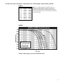
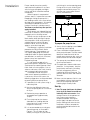
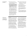
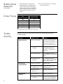
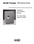
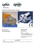
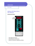
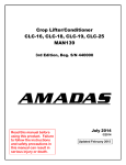
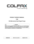
Zenith Pumps B-9000
Gear Pumps
®
Installation,
Care and
Maintenance
Zenith
Chemical Duty
Gear Pumps
®
Thoroughly read and understand this entire manual
before installation and operation of pump.
®
Zenith
In 1926, Zenith Pumps was approached
by the synthetic fiber industry to design
a pump that would provide precise,
pulseless and repeatable flow while
ensuring ultimate product quality. The
options then were the same as those in
the chemical process industry today—
diaphragm, lobe, coarse gear, piston,
plunger and screw pumps. Each has
problems with pulsation, flow inaccuracies, multiple seal areas and slip, which
require constant calibration, high maintenance and extended downtimes.
Zenith Pumps met the challenge
and designed a rotary external gear
pump of unique precision and simplicity.
Manufacturing techniques were developed to hold tolerances to ±.00005",
minimizing internal clearances and
assuring accurate and precise metering.
The pump’s simplistic design of only
three moving parts – two metering gears
and a drive shaft – provided long life
and reduced maintenance.
For years, engineers have relied on
Zenith to provide precision fluid handling solutions for their most difficult
pumping applications. Zenith gear
pumps can be found wherever precise,
pulseless, and repeatable metering of
fluids is required.
Benefits
High Accuracy — Stable, repeatable
accuracy, ensures an exact volume
per revolution without expensive flow
meters.
flows are assured even under varying
conditions of temperature, viscosity and
pressure.
Precision Construction — Ground and
lapped components allow for operating
clearances to .00015" and provide high
volumetric efficiency.
Minimum Pulsation — Unique design
offers virtually pulseless flow without
valves or flexible elements to hinder
performance.
Active Flowmeter Concept —
Unparalleled mechanical precision,
combined with the closed loop set point
Specifications
three moving parts and 400 series
stainless steel construction, the pump
provides excellent corrosion resistance
for most chemical processes, and is
through-hardened to 54 Rc or better for
maximum life.
Experience — Zenith has over 74
years of application experience with
engineers available 24 hours a day to
support your precision fluid metering
needs.
Capacities (cc/rev): 0.05, 0.3, 0.6, 1.2,
Seals:
2.4, 4.5, 9.0, 15, 30, 45, 90
Single Mechanical, Double Lip,
Packed or Magnetic
Recommended Speed:
.05 to 30 cc/rev, up to 500 RPM
45 & 90 cc/rev, up to 300 RPM
Rotation:
Flow Range:
Port Connections:
up to 27,000 cc/Minute, (7 GPM)
Metric thread or SAE 61 Standard
Inlet Pressure: 300 psi (20 Bar) Max.
Outlet Pressure: 1000 psi (70 Bar) Max.
Differential Pressure:
Optional Port Adapters:
Clockwise (CW) facing drive shaft
20 to 1000 psi. (viscosity dependent)
M12 X 1/4" NPT . . . . . . . . . 0.05 – 2.4 cc/rev
1/2" SAE X 1/2" NPT . . . . . . 4.5 – 9.0 cc/rev
3/4" SAE X 3/4" NPT. . . . . . . 15 – 30 cc/rev
1-1/4" SAE X 1-1/4" NPT. . . 45 – 90 cc/rev
Temperature:
Optional Band heaters:
0° F (-18° C) Minimum
400° F (205° C) Maximum (with magnetic
coupling seal)
645° F (340° C) Maximum (dependant on
shaft seal materials)
2
Low Cost of Ownership — With only
150 Watt, 115 VAC . . . . 0.05 – 2.4 cc/rev
325 Watt, 115 VAC . . . . 4.5 – 9.0 cc/rev
650 Watt, 230 VAC . . . . . 15 – 30 cc/rev
1500 Watt, 230 VAC . . . 45 – 90 cc/rev
Design
Zenith’s B-9000 Series precision metering pumps utilize a rotary external spur
gear which dispenses an exact volume
of fluid per shaft revolution (cc/rev).
Precision ground and lapped construction, including alignment dowels,
allows for close control of operating
clearances. This ensures precise,
pulseless and repeatable flow under
varying process conditions.
Integrated closed loop speed control and a compact motor driver system
maintains up to .01% accuracy of set
point speeds and also accepts automated interfaces.
The B-9000 Series is constructed of
400 series stainless steel, providing
excellent bearing qualities (hardness 54
Rc) and corrosion resistance for most
chemical processes. The pump offers
increased uptime while minimizing maintenance due to its simple design of only
three moving parts.
The B-9000 Series is a new generation of Zenith’s traditional B-Series pump.
While maintaining precise flow characteristics, its optimum gear design
reduces bearing loads, while increasing
speed capability. The pump allows
direct piping and shaft engagement and
includes a single mechanical shaft seal,
(other seal types available).
Operation
Fluid enters the pump through the inlet
port located in the front plate and fills
the gear pocket. As the gears rotate, a
precise amount of fluid is trapped by the
side walls of the gear pockets and gear
teeth.
The metered fluid is transported by
the rotation of the gears to the discharge
side of the pump where the gear teeth
come into mesh. This action forces the
fluid out of the gear teeth and through
the outlet port located in the front plate.
The pressure developed is determined
by the pump size, the gear clearances,
pump speed, fluid viscosity and impedance to flow.
Pump speed is limited by practical
considerations. If a high viscosity fluid is
being metered and pump speed is
increased beyond a certain point, the
fluid may not be able to fill the gear
teeth spaces, and the pump will not
obtain enough fluid to maintain normal
volumetric efficiency. Lack of sufficient
fluid is called starvation or cavitation.
This can be remedied by increasing the
inlet pressure or reducing pump speed.
See table 1 on page 5.
Metering of thin fluids requires a
different approach. Since the pump
depends upon the metered fluid for
lubrication of internal bearing surfaces,
speeds are normally limited. These
bearing surfaces include the bearing
areas in the front and rear plates, and
the driver gear turning about the arbor.
Accelerated wear and even seizure may
be the result of high speeds, especially
if attended by low lubricity or a fluid
containing abrasive particles. In certain
applications, it is recommended to use a
pump of larger capacity operated at a
lower speed. Contact our Applications
Engineering Department for assistance.
Pump efficiency depends on four
basic variables: fluid viscosity, gear
clearances, differential pressure and
pump speed. The less viscous the fluid,
the more likely it is to flow through a
given orifice. In a Zenith pump, this
orifice is the gear clearance. Differential
pressure forces the fluid through this
clearance at a steady rate, regardless
of the pump speed. Thus, the slip is
constant for a given amount of time. The
actual delivery of fluid is the measured
delivery minus the slip. If we increase
the pump speed we increase the measured delivery, while the slip remains
constant, causing the pump to become
more efficient. Likewise, if we slow the
pump down, the pump becomes less
efficient. Slip is repeatable and predictable, and pump operation can be
adjusted to compensate and, thus,
accuracy is very high. See Graph 1 on
page 5.
Zenith B-9000 Series pumps are
designed for operating temperatures
less than 645°F. When operating at
temperatures above ambient, heat
jackets should be used, and pumps
should be heated slowly and uniformly
to avoid warpage and internal component
interference.
The 400-Series stainless steels used
in the construction of the B-9000 Series
pumps provide sufficient corrosion
resistance for most standard chemical
processes. The material hardness will
provide a high degree of wear resistance
as well. However, processes involving
corrosive or abrasive fluids should
always be reviewed by Zenith.
3
Operation
(continued)
Magnetic Coupling Pumps
In normal operation, the magnetic poles
of the outer drive magnet remain aligned
with the magnetic poles of the inner
pump magnet. The motion of the motor
is smoothly transferred to the pump
shaft. If the torque load on the pump
exceeds the magnetic coupling
strength, then the outer magnets will
rotate past the inner magnets and the
magnetic poles will misalign. The outer
magnet will increase to a no-load motor
speed while the inner magnet remains
relatively motionless. Excessive noise
and vibration can be observed as the
poles of a decoupled magnet move past
one another.
The pump should be stopped
immediately if the magnets decouple.
Continued operation of the motor with
the magnets decoupled will reduce the
future strength of the coupling. The
magnets will not properly realign until
the motor has been stopped. Before
restarting the motor, one should determine the cause of the decoupling and
remedy the problem. Decoupling does
not necessarily indicate a pump failure.
It indicates that an instantaneous torque
requirement of the pump has exceeded
the strength of the magnetic coupling
supplied with the system.
Without disassembly of the pump it
can be difficult to determine whether the
magnetic coupling or the pump internals
are operating incorrectly. The following
is a list of examples that could result in
magnet decoupling:
• Blockage or restriction in the discharge side of the system
• Discharge pressure in excess of
nominal conditions
• Too rapid acceleration or deceleration of the drive system
• An increase in fluid viscosity
• Foreign particles impinging upon
pump internal components
• Increased friction due to a poorly
lubricating process fluid
4
The decoupling characteristic of magnets can be a safety feature, preventing
inadvertent pump/motor overloads.
Magnets should be chosen so that their
decoupling torque is greater than the
pump input torque. This should include
any transient, starting, and stopping
conditions in addition to steady state
values.
The decoupling torque can vary with
different fluids, temperatures, operating
pressures, and magnet sizes. Accurate
sizing of magnets for a specific application
requires precise knowledge of several
operating conditions. Check with your
Zenith representative to see which 9000MD system is appropriate.
General Magnetic Coupling
Precautions
WARNING
Both the inner and outer magnetic
rotors are very powerful. Handle them
with care.
Danger! Persons with cardiac pacemakers
should stay at least 8 feet from the
magnetic product at all times.
Do not position hands or fingers so that
they may become trapped between the
two magnetic rotors, or between one
magnet and a metal object.
Do not position the magnets near one
another unless assembling the pump to
the system. Both rotors should be fastened to their respective shafts before
bringing them into proximity.
Do not place the magnets near any electronic equipment or media that is sensitive to magnetic fields (computers,
diskettes, credit cards, etc.)
When storing and assembling the
magnetic coupling, make sure that no
small metallic fasteners, pieces or other
foreign objects adhere to the rotors or
barrier cap.
If the magnets de-couple, stop the drive
system for the pump immediately.
Determine the cause of the excessive
torque requirement and remedy the
problem prior to re-starting the system.
Inlet Pressure Loss (psi) = Viscosity(cps) • Displacement(cc/rev) • Shaft Speed(rpm) • [(Specific Gravity • W1)+W2]
Table 1
cc/rev
0.3
0.6
1.2
2.4
4.5
9.0
15.0
30.0
45.0
90.0
W1
4.29E-06
1.93E-06
1.21E-06
9.34E-07
3.00E-07
2.24E-07
1.11E-07
8.61E-08
3.38E-08
2.49E-08
W2
2.32E-06
2.47E-06
2.77E-06
3.38E-06
3.46E-07
4.19E-07
7.47E-08
9.28E-08
1.65E-08
2.02E-08
Note: This sizing procedure should be used as a
guideline for estimating pump type, pump size
and system requirements. Please consult Zenith to
confirm pump and system selection prior to placing
a purchase order.
Graph 1
B-9000 or H-9000 Pump Performance
1.00
0.90
cc/r
ev
ev
cc/r
cc/rev
rev
15 cc/
1
9 & 30
4.5 &
0.1
.05
2.4
c/rev
90 c
0.01
ev
0.001
c/rev
0.00
cc/r
0.10
Key:
∆P = Pressure (psi)
µ = Viscosity (cp)
N = Speed (rpm)
45 c
0.20
ev
0.30
1.2
0.50
0.40
cc/r
ev
cc/r
0.60
0.6
0.70
0.3
Derating Factor
0.80
10
100
∆P/(µ•N)
Flowrate = pump capacity (cc/rev) x rpm x performance factor
5
Installation
Pumps should always be carefully
unpacked and inspected. If any items
are missing or damaged, the freight
carrier and Zenith should be notified
immediately.
While the pump is composed of
stainless steel, it is a precision instrument.
Dropping or hitting the pump with a
non-yielding material can cause serious
damage to the components. All materials
are through-hardened to maximum
hardness resulting in a brittle material.
Treat them as you would any other precision
gaging instrument.
Zenith pumps are shipped filled with
mineral oil. If necessary, flush the pump
thoroughly with a cleaning solvent.
Prior to start-up, the pump must be
lubricated by either priming the pump
with the process fluid, or by pouring a
suitable lubricant into the inlet port.
Rotate the drive shaft until lubricant
appears at the discharge port.
The following is a general installation
procedure for Zenith B-9000 Series
metering pumps. The procedure may
vary slightly depending on the exact
model purchased. For special applications,
considerations, or technical assistance,
please contact our Applications
Engineering Group.
It is not recommended to flush
downstream process equipment utilizing
Zenith precision metering pumps. Most
fluids used as flushing agents, such as
solvents and water, have a low viscosity
and have poor lubricating qualities.
Catastrophic failure may occur
under certain operating conditions. If it
is necessary to flush the system, the
following suggestions are recommended
to prevent premature pump failure:
1. If possible, flush the system using a
lubricating fluid.
2. Minimize the differential pressure
across the pump ports to a maximum
of 25 psi.
3. Reduce the pump speed to an
acceptable level (approximately
10 rpm)
4. Flush the pump for the shortest
allowable time, yielding effective
cleansing of the system, and no
longer than necessary.
5. It is recommended to use a bypass
around the pump as illustrated in
Figure A. This will allow for high
velocity flushing of the system while
6
minimizing risk to the metering pump.
During the flush cycle, fluid will pass
through and around the pump. This
will allow the system to be flushed
quickly and effectively.
Figure A
Pump
Bypass
Valve
To prepare the pump for use:
1. Always flush the piping system before
connecting it to the pump.
2. Filters should be installed upstream
of the pump inlet port. The filter should
ideally be sized to one half of the
pumps gear clearances but, must not
restrict the flow of fluid to the inlet port.
3. Turn pumps by hand before start-up
to ensure free rotation.
4. For applications above ambient temperatures, if using heaters, heat the
pump slowly and evenly (including
the seal arrangement) prior to
introducing fluid into the pump. This
prevents thermal shock and material
distortion.
5. Make sure that process fluid is in the
pump before starting. Apply positive
pressure to the pump inlet when
metering high-viscosity fluids.
Start Up
1. Note: The pump should never be allowed
to run dry or be allowed to run with nonlubricating fluids such as water. Allow
enough time for all components of
the system to reach process
temperature before starting the
pump. Apply inlet pressure to the
pump, allowing time to ensure that
the process fluid has entered the
pump to provide lubrication for the
bearing areas.
Installation
(continued)
2. Before starting, remove all flow
restrictions downstream of the pump
to allow initial operation with as low a
back pressure as possible.
3. Start the pump at the slowest speed possible and, if possible, with a lubricating
fluid. Zenith B-9000 pumps must never be
run without a fluid. Watch the point of
discharge for evidence of fluid. If no
discharge is seen after a reasonable
length of time, shut down the pump
and check for obstructions in the system and proper pump rotation. The
term “sufficient length of time” is subjective, and cannot be quantified
because of differences in installation.
If, for example, a connection can be
broken within a few inches of the
pump outlet port, the flow would be
evident with several seconds. If the
distance between the pump outlet
and the point of final discharge is
long, more time would be needed
before flow is confirmed.
Cleaning,
Inspection
and Repair
Remember: Zenith metering pumps are
made for exact duty. In order to develop
high pressure and minimize slip, the
clearance between the metering gears
and their housing must be as small as
possible, yet large enough to allow adequate lubrication. All parts are machined
to extreme accuracy. Critical dimensions
are held between one and two tenthousandths of an inch (.0001"/.0002").
Accurate performance is dependent
upon proper handling. Please handle
the pumps with extreme care, and if possible, set aside a separate clean area for
pump maintenance and repair.
It is recommended that pump users
institute a program for dimensional
inspection of critical parts in order to
keep maintenance and operating costs
to a minimum. By noting the performance
Note: The pump will discharge a cloud of
bubbles when it is started, but this
will subside when the air is purged
from the pump. This is a normal
part of pump startup.
4. When satisfactory operation is
achieved, the pump and system can
gradually be brought up to normal
operating speed and pressure.
4. Listen for any sounds of distress
when first starting the pump and turn
the pump off immediately if any are
heard. Investigate for causes of
distress.
5. If, at any time during operation, the
pump does not appear to be running
smoothly, stop the pump immediately
to avoid serious internal damage.
of a pump immediately before removing
it from service and correlating the performance to measured component wear,
the maximum limit for the pump’s critical
components can be established.
Additionally, the service life of the pump
can be predicted and downtime can be
scheduled accordingly.
If necessary, any Zenith precision
metering pump requiring maintenance can
be returned to the factory for complete
repair and overhaul. For a large number
of pumps, Zenith offers a contract repair
service which helps to reduce repair
costs and delivery time. Zenith Pumps
also offers pump maintenance seminars.
For more information concerning Zenith
pump repair services, please contact our
Customer Service Department.
7
Lapping or
Blocking
To remove nicks, burrs and scour marks
from pump parts, place two layers of
400-Grit Emery Cloth on a lapping block
or plate. A granite flat is also suitable.
Apply light pressure to the part and turn
it using a figure 8 motion approximately
ten times until a smooth finish appears.
Areas that are commonly lapped are the
sides of metering gears and the inside
faces of front, gear and rear plates. After
lapping is completed the parts are ready
to be cleaned with a safe industrial solvent.
Always use clean, lint free rags and
compressed air to clean components.
Paper towels are not acceptable
because they can leave small pieces of
paper and dust on the pump parts.
Use chemical brushes to clean between
gear teeth, bores and reliefs. After all
components are “hospital clean”, the
pump can be reassembled.
If cleaned parts are not to be
reassembled for a period of time, they
should be coated with a rust preventative
fluid, such as mineral oil, to prevent
rusting.
New and replacement parts should
always be deburred and cleaned using
the above procedures.
B-9000 Series
Disassembly
Note: As parts are disassembled, place
them carefully on a clean surface such
as a soft cloth. Do not allow them to
knock together. Pay close attention to the
order in which parts are removed. This
will aid in the reassembly of the pump.
Instructions below assume the pump
has been removed from the system, for
example, magnetically driven pumps
with adapter plates have been disengaged from the housings.
• On the .05 through 2.4 cc/rev
models, set screws will have to be
removed to allow removal of the
mechanical seal (13) from the drive
shaft (2). On models larger than 2.4
cc/rev, first remove the carbon seal
face from the seal, then pull the
mechanical seal (13) from the drive
shaft (2). Some materials of the
seal (face) are brittle in nature, use
extreme caution so as not to damage the seal or its components.
Caution: Please review the precautions
listed on Page 4 for Magnetically
Coupled Pumps.
1. Remove the square key (17).
For Magnetically Coupled Pumps
skip to step 3d.
2.
For mechanical face seal and double
lip seal pumps, remove the socket
head screws (18) from the seal
housing (11). For packing seal
pumps, remove the hex head
screws (15) from the packing gland
(14), then lift off the packing gland.
3. Lift off the seal housing (11) and
remove the seal.
a) Mechanical Face Seal Pumps:
• The ceramic seat may be removed
from the housing by pushing it out
with finger pressure. If it is stuck,
use two small Allen keys or other
small pins to press the seat from
the housing using the two access
holes on the housing face.
• Remove the o-ring (15) from the
recessed area in the seal housing
(NOTE: .05 through 2.4 cc/rev
models do not have the o-ring).
8
b) Double Lip Seal Pumps:
• Press the lip seal (51) from the seal
housing using finger pressure, or
by pressing on the seal using a
plastic tool.
c) Packing Seal Pumps:
• Remove the packing seal rings (13)
from the Inside of the seal housing
(11).
• Remove the collar plate (12) from
the drive shaft (2).
d) Magnetically Coupled Pumps:
• If applicable, remove the screws
that secure the barrier cap to the
adapter plate. Remove the barrier
cap and its O-Ring. NOTE: There
could be process fluid contained in
the barrier cap.
• Loosen setscrew at the bottom of
the inner rotor with appropriate
Allen wrench. NOTE: Beware of
strong magnetic forces. Slide the
inner rotor off the shaft.
• Remove the square key from the
pump shaft.
• Remove the four socket head
screws/washers that are securing
B-9000 Series
Disassembly
(continued)
the adapter plate to the pump
body. Lift the adapter plate off the
pump body and retrieve the ORing.
4. Loosen and remove the socket head
screws (19) and (20) from the back
of the rear plate (7).
5. Remove the rear plate (7). Always
use the pry slots to prevent scratching
precision tapped surfaces.
6. Remove the gear plate (3), being
careful to note the alignment of any
markings on the plate. Always use
the pry slots to prevent scratching
the plates.
Caution: Do not allow metering gears to
be lifted out with the gear plate. They
may drop, causing damage to the gear
teeth. Note that the slip-fit dowels (10)
may come off with the gear plate.
8. Remove the driving gear (5).
9. Remove the round key (4).
10. Remove the drive shaft (2) from the
front plate (8).
11. Remove the driven gear (6) from the
arbor (9).
12. Remove the slip-fit dowels (10) by
turning and pulling simultaneously.
13. If the arbor (9) is to be replaced or
thoroughly checked, press out by
using an arbor press, pressing
toward the inside of the pump (the
shortest press distance).
14. Replace sleeve bearings (32 & 34)
in front and rear plates as necessary
and hone in the plate to the original
new part specifications. Contact
Zenith for dimensions. NOTE: .05
through 2.4 cc/rev models do not
have sleeve bearings.
7. Remove the retaining ring (16) from
the shaft (2) which holds the driving
gear (5) in place.
Inspection
and Part
Preparation
After the parts have been cleaned,
they should be inspected for nicks,
burrs and stubborn residue. The gears
and the edges of the gear plate pockets
are the most likely areas to be damaged
because of sharp edges. An illuminated
magnifier facilitates examination.
1. All flat surfaces of plates and gears
should be “blocked”. Blocking is the
act of rubbing the flat surface of a part
on 400-grit, 500-grit or 3/0 abrasive
paper, which is supported on a
machinist’s or inspector’s surface
plate. A few light but firm rubs usually
are enough to remove residue and
minor metal disturbances. Remember
to use a figure 8 pattern to retain flatness and perpendicularity of holes
when lapping plates.
1. Heavy disturbances or residue on
front or rear plates (NOT the gear
plate!) may require stronger blocking
on 320-grit or even 240-grit abrasive
paper followed by blocking on a finer
abrasive paper. Deep score marks or
metal transfer cannot be removed by
blocking, and the surfaces must be
ground. When surfaces are ground,
care must be taken to maintain the
perpendicularity of the precision
ground holes with the inner plate surface. The gear plate should never be
ground; to do so would reduce the
axial gear clearance to the point
where interference might occur when
the pump is reassembled. Gears can
be ground as well, but interchangeability and clearances are altered.
Grinding gears is NOT recommended!
2. Gears, shafts and arbors should be
lightly polished on the O.D.
3. Any nicks in the gear teeth should be
removed by carefully stoning the
parts with a fine India oilstone or an
Arkansas stone.
4. The edges of the gear’s I.D., bearing
holes and dowel holes should be
lightly stoned with a round Arkansas
stone to remove any nicks. Then polish
the I.D. with a small piece of fine
abrasive paper, 400-grit or finer.
5. After all preparation has been completed, remove the abrasive grain
and loose residue in an ultrasonic
cleaner or other suitable cleaning
method. Abrasive grain is larger in
size than the pump clearances.
6. At this point, dimensional inspection
may be made if desired.
9
.05 - 2.4 cc/rev B-9000
Retaining Ring 16
Key 4
Square Key 17
Interpret per
ASME-Y14.5M 1994
Driving Gear 5
19 SHCS M8x1.25
Gear Plate 3
7 Rear Plate
9 Arbor
Front Plate 8
2 Drive Shaft
6 Driven Gear
10 Hollow Dowel
13 Type 8-IT Mechanical Seal
11 Seal Housing
21 Dryseal Type Plug
18 SHCS M4x0.7
Diagram 1
4.5 & 9 cc/rev B-9000
Rear Plate Assembly 7
Retaining Ring 16
Round Key 4
Interpret per
ASME-Y14.5M 1994
20 SHCS M6x1
Driving Gear 5
19 SHCS M10x1.5
Gear Plate 3
33 Rear Plate
Front Plate Assembly 8
34 Sleeve Bearing
9 Arbor
6 Driven Gear
10 Hollow Dowel
O-Ring 15
32 Sleeve Bearing
Square Key 17
31 Front Plate
2 Drive Shaft
13 Type 502 Mechanical Seal
11 Seal Housing
18 SHCS M6x1
Diagram 2
10
15 & 30 cc/rev B-9000
Rear Plate Assembly 7
Retaining Ring 16
Round Key 4
Interpret per
ASME-Y14.5M 1994
Driving Gear 5
20 SHCS M6x1
Gear Plate 3
19 SHCS M12X1.75
Grade 12.9
33 Rear Plate
Front Plate Assembly 8
34 Sleeve Bearing
9 Arbor
6 Driven Gear
10 Hollow Dowel
O-Ring 15
32 Sleeve Bearing
31 Front Plate
2 Drive Shaft
13 Mechanical Seal
11 Seal Housing
18 SHCS M8x1.25
Diagram 3
45 & 90 cc/rev B-9000
SHCS M16x2 19
Rear Plate Assembly 7
Retaining Ring 16
Round Key 4
Interpret per
ASME-Y14.5M 1994
20 SHCS M6x1
Driving Gear 5
33 Rear Plate
Gear Plate 3
34 Sleeve Bearing
Front Plate Assembly 8
10 Hollow Dowel
Square Key 17
9 Arbor
6 Driven Gear
O-Ring 15
32 Sleeve Bearing
Mechanical Seal 13
31 Front Plate
2 Drive Shaft
11 Seal Housing
18 SHCS M8x1.25
Diagram 4
11
B-9000 Series
Assembly
Use both pages of the assembly drawing during the reassembly process to
assure correct orientation of all parts.
Considerable care should be taken
to prevent wedging or jamming of parts.
Never force the parts together. They will
drop into place if properly aligned.
Note: If the pump will not turn freely
after each component is installed,
then the last piece installed needs
additional attention or replacement.
Provide a can of compatible lubricant,
preferably SAE-50 motor oil or mineral oil.
If the pump is to be used at temperatures
greater than 212°F (100°C), lubricant
should be chosen for high temperature
service. Shaft, arbor, dowels, and gears
should be lubricated prior to assembly.
Take care to remove excess fluid from
between the plate surfaces using a clean
towel. Threads should be lubricated with
a temperature-rated, anti-seize compound.
For service under 212°F (100°C), a molydisulfide-based grease may be used.
During assembly, considerable care
should be taken to prevent wedging or
jamming of close-fitting components.
Never force the parts together. They will
drop into place if properly aligned.
Caution: Please review the precautions
listed on Page 4 for Magnetically
Coupled Pumps.
1. Place the front plate (8) on a flat
surface with the inner surface of
the plate facing up.
2. If the arbor (9) was removed, press
arbor into the front plate (8) using
the driven gear (6) as a guide for
pressing the arbor perpendicular
(upright) into the plate.
3. Push the slip-fit dowels (10) into the
dowel holes in the front plate (8).
4. Place the driven gear (6) on the
arbor (9).
5. Place the gear plate (3) over the
dowels (10) and driven gear (6).
On .05 through 2.4cc/rev models,
the gear plate may be installed in
either direction. On models larger
than 2.4cc/rev, align the clearance
hole for the fastener (19) with the
corresponding tapped hole on
the front plate.
6. Install the drive shaft (2) from the
opposite side of the front plate.
12
7. Install the round key (4) into the
keyway on the drive shaft.
8. Slide the driving gear (5) onto the
drive shaft and into the gear plate.
Take care to align the keyway in the
gear with the key (4). The key may
need to be held down to prevent it
from being damaged by the gear.
9. Install the retaining ring (16) on the
rear plate end of the drive shaft (2).
10. Install the rear plate (7).
11. Install the socket head screws (19)
through the rear plate (7) and torque
to 50% of recommended torque
(see table page 14) using a crossing pattern. Check for free rotation
of the gears. If acceptable, continue
to torque to full recommended
torque. Again, check for free rotation
of the gears.
12. Install the socket head screw (20)
through the rear plate (7) and torque
to recommended value.
13. Install the seal onto the drive shaft (2).
NOTE: To facilitate assembly of the shaft
seal, place the pump on a flat surface
with the shaft in a vertical position.
a) Mechanical Face Seal Pumps:
• The mechanical seal (13) will be
installed onto the drive shaft (2) with
the carbon end facing away from
the front plate (8). Take care when
pressing the seal onto the shaft, as
the elastomer can be damaged by
the keyway or shaft edge.
• On the .05 through 2.4 cc/rev models,
align the set screws with the grooves
machined in the drive shaft (2), then
tighten the set screws. On larger
models, the seal will slide up the
shaft until it rests against the collar.
• On 4.5 cc/rev and larger models,
install the o-ring (15) into the recess
in the seal housing (11). If necessary,
use heavy silicone grease to keep
the o-ring in place.
• On 4.5 cc/rev and larger models,
install the carbon seat into the
mechanical seal with the exposed
rib of the seat toward the ceramic
seat of the seal assembly. The
notches of the carbon seat should
mate with the tabs of the mechanical seal. Use heavy silicone grease
to keep the seat fitted to the
mechanical seal.
B-9000 Series
Assembly
(continued)
• Install the ceramic seat into the seal
housing (11) with the o-ring of the
seat away from the mechanical seal.
• Gently slide the seal housing (11)
over the drive shaft (2) until the seal
housing is in place and lined-up with
the bolt holes on the front plate (8).
• Install the socket head screws (18)
into the seal housing (11) and tighten
to the recommended torque. NOTE:
On the .05 through 9 cc/rev models,
tighten the screws using a crossing
pattern.
b) Double Lip Seal Pumps:
NOTE: The seal assembly tool (52) is
required for lip seal installation.
• The inner diameter of the lip seal
(51) must first be shaped before
installing onto the drive shaft (2).
Slide the lip seal over the seal
assembly tool (52) with the springs
of the lip seal being the last side
inserted. The lip seal should be
allowed to sit for 10-15 minutes to
allow for expansion of the lips.
• After the lips have expanded, the lip
seal (51) should be slid off of the
seal assembly tool (52), flipped
over, and then reinserted onto the
seal assembly tool so that the
springs are the first side inserted.
• Once reinserted onto the seal assembly tool (52), coat the outer rim of the
lip seal (51) with a lip seal lubricant.
• The lubricated lip seal (51) and the
seal assembly tool (52) to which it is
attached should be directed into the
seal housing (11) so that the spring
of the lip seal faces away from the
rear of the seal housing. The seal
assembly tool should be inserted
completely into the seal housing and
guided through the drive shaft hole
until the lip seal touches and is flush
with the rear wall of the seal housing.
Make sure there is no gap between
the lip seal and the seal housing.
• Place the open end of the seal
assembly tool (52) over the pump
drive shaft (2). NOTE: Make sure that
the key (17) is not in place on the drive
shaft. Slide the lip seal (51) and seal
housing (11) along the seal assembly
tool until it smoothly glides over the
drive shaft. Continue until the seal
housing is in place and lined-up with
the bolt holes on the front plate (8).
• Install the socket head screws (18)
into the seal housing (11) and tighten to the recommended torque.
NOTE: On the .05 through 9 cc/rev
models, tighten the screws using a
crossing pattern.
c) Packing Seal Pumps:
• Slide the collar plate (12) over the
drive shaft (2).
• Install four new packing rings (13)
into the packing housing (11).
• Gently slide the packing housing
(11) over the drive shaft (2). If
necessary, use the flat side of the
packing gland (14) to push the
packing housing into place to
prevent the packing rings from
being pushed out of the packing
housing.
• Use the packing gland (14) to
slightly compress the packing rings
(13) and properly position the packing housing (11).
• Remove the packing gland (14),
taking care not to move the packing
housing (11). Install the socket head
screws (18) through the packing
housing (11) and the collar plate
(12) into the front plate (8). Tighten
to the recommended torque.
• Place the packing gland (14) into
position over the packing housing
(11). Install the hex head bolts (15)
through the packing gland and
tighten finger tight.
d) Magnetically Coupled Pumps:
• Insert the smaller O-Ring into the
groove on the adapter plate, using
compatible grease to retain the
O-Ring into the groove.
• Install the plate with the O-Ring
facing the pump body using the
four socket head screws and
sealing washers.
• Insert the square key onto the pump
shaft, then slide the inner magnet
onto the shaft. Refer to certified
pump assembly drawing to determine the correct height/placement
of the magnet. NOTE: This is critical
to the pumps proper operation.
• Secure the inner magnet by
tightening the setscrew upon
the square key.
continued
13
B-9000 Series
Assembly
(continued)
Screw Torque
• Place the larger O-Ring into the
exposed face of the adapter plate.
Lower the barrier cap into position
over the inner magnet. If applicable
mount the barrier cap by installing/
tightening the eight socket head
screws.
Size
(Metric Alloy Steel)
M4
M6
M8
M10
M12
M16
14. Install the square key (17) into the
drive shaft keyway.
Recommended
Torque (in -lbs)*
31
108
262
519
910
2250
*Lubricated values/if non-lubricated increase by 33%.
Troubleshooting
Possible malfunctions of the pump with their causes and remedies are listed in
the following table.
Trouble
Probable Cause
Remedy
Pump will not turn
1) Drive malfunction
Verify that drive powered.
Assure that alarm circuits are
clear. Check motor drive
current and speed settings.
2) Process conditions
changed
Check process conditions
for proper temperature,
pressures, viscosities and
materials.
3) Entrained particle
Disassemble and clean
pump; replace any damaged
parts.
4) Possible internal
damages
Disassemble and clean
pump; replace any damaged
parts. Consult factory.
1) Worn seal face(s)
Replace seals.
Excessive seal
assembly leakage
2) Improperly positioned Check seal and faces for
seal or faces
proper position.
Reduced pump
efficiency
14
3) Excessive inlet
pressure
Reduce inlet pressure.
1) Worn gear(s)
Replace worn gear(s).
3) Process conditions
changed
Consult factory for gear
clearance recommendations
for new process conditions.
FAILURE, IMPROPER SELECTION OR IMPROPER USE
OF THE PRODUCTS AND/OR SYSTEMS DESCRIBED
HEREIN OR RELATED ITEMS CAN CAUSE DEATH,
PERSONAL INJURY AND PROPERTY DAMAGE.
WARNING
This document and other information from Zenith
Pumps, its subsidiaries and authorized distributors provide product
and/or system options for further investigation by users having
technical expertise. It is important that you analyze all aspects of
your application and review the information concerning the product
or system in the current product catalog. Due to the variety of
operating conditions and applications for these products or systems,
the user, through its own analysis and testing, is solely responsible
for making the final selection of the products and systems and
assuring that all performance, safety and warning requirements
of the application are met.
The products described herein, including without limitation,
product features, specifications, designs, availability and pricing,
are subject to change by Zenith Pumps and its subsidiaries at any
time without notice.
ISO 9001: 2000 Registered
Zenith® Pumps
A Colfax Buisiness Unit
1710 Airport Road
Monroe, NC 28110
Phone: 704-289-6511 • Fax: 704-289-9273
[email protected] • www.zenithpumps.com
© Copyright 2000 Zenith Pumps
B-9000 C&M 12/04