1
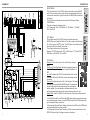
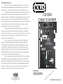
LIMITED WARRANTY
This product is warranted to the original consumer purchaser to be free from
defects in materials and workmanship under normal installation, use and service for a
period of one (1) year from the date of purchase as shown on the purchaser’s receipt.
The obligation of Rolls Corporation under this warranty shall be limited to repair
CS1000
or replacement (at our option), during the warranty period of any part which proves
defective in material or workmanship under normal installation, use and service, provided
the product is returned to Rolls Corporation, TRANSPORTATION CHARGES PREPAID. Products returned to us or to an authorized Service Center must be accompanied by
a copy of the purchase receipt. In the absence of such purchase receipt, the warranty
CABLE SCANNER
1
period shall be one (1) year from the date of manufacture.
This warranty shall be invalid if the product is damaged as a result of deface-
BATTERY 9 V
2+
3-
ment, misuse, abuse, neglect, accident, destruction or alteration of the serial number,
improper electrical voltages or currents, repair, alteration or maintenance by any person or
party other than our own service facility or an authorized Service Center, or any use
violative of instructions furnished by us.
This one-year warranty is in lieu of all expressed warranties, obligations or
liabilities. ANY IMPLIED WARRANTIES, OBLIGATIONS, OR LIABILITIES,
TONE OUTPUT SIDE
4+
+ = positive polarity
- = negative polarity
1 = ground
2+
LIMITED IN DURATION TO THE ONE YEAR DURATION OF THIS WRITTEN
3-
warranty lasts, so the above limitation may not apply to you.
IN NO EVENT SHALL WE BE LIABLE FOR ANY SPECIAL, INCIDENTAL
OR CONSEQUENTIAL DAMAGES FOR BREACH OF THIS OR ANY OTHER
WARRANTY, EXPRESSED OR IMPLIED, WHATSOEVER. Some states do not allow
the exclusion or limitation of special, incidental or consequential damages so the above
limitation or exclusion may not apply to you. This warranty gives you specific legal
1
1
2+
34+
5
6
7
+3
2
1
-30
3-
2+ 1
3
0
4
1
CHANTABILITY AND FITNESS FOR A PARTICULAR PURPOSE, SHALL BE
1
1
2
-10
-20
2+
2
pwr
3-
1
3
CABLE
TEST
OFF
2+ 1
INCLUDING BUT NOT LIMITED TO THE IMPLIED WARRANTIES OF MER-
LIMITED WARRANTY. Some states do not allow limitations on how long an implied
TEST
TONE
2+
1
dB
+7
1
TONE LEVEL
(NOTE: Levels indicated are BALANCED.
For unbalanced levels, subtract 6 dB. )
32+
2
3
2
2
1
MADE IN USA
PHANTOM POWER
PRESENT
RECEIVE
LINE
1
2+
34+
5
6
1
2+
34+
5
6
7
8
SEND
LINE
1
1
2
2
3
3
4
>52
4
5
>42
5
6
>32
6
7
>21
7
8
>11
8
PHANTOM POWER
VOLTAGE
3
3
1
1
2
3
4
5
6
7
1
2
3
4
5
6
1
2
3
4
5
6
7
8
rights, and you may also have other rights which vary from state to state.
• Cable Scan
• Test Tone Generator
• Phantom Power Test
ROLLS CORPORATION
SALT LAKE CITY, UTAH
10/03
RY
A
N
MI
I
EL
R
OWNERS MANUAL
P
INTRODUCTION
SPECIFICATIONS
Thank you for your purchase of the Rolls CS1000 Cable Scanner. In addition to testing
ten different cable ends, it has a variable level 1 kHz Tone Generator for testing audio
equipment, and a Phantom Power voltage and phase tester. This device was designed
with the audio professional in mind. Please take a moment and review this manual as it
contains important information for proper operation of the CS1000.
Scan rate:
Test Tone frequency:
Test Tone level:
Tone output impedance;
PLEASE NOTE: This Owners Manual assumes the user
has a basic working knowledge of audio equipment and
connectors.
To prolong battery life, remember to move the TEST
TONE / CABLE TEST switch to the OFF position when
the CS1000 is not in use
INSPECTION _____________________________________________________
1. Unpack and inspect the CS1000 box and package.
If obvious physical damage is noticed, contact the carrier immediately to make a
damage claim. We suggest saving the shipping carton and packing materials for
safely transporting the unit in the future.
2. Please complete our online Warranty Registration by visiting our website;
www.rolls.com. Click on the REGISTER YOUR WARRANTY HERE line. Or,
complete the Warranty Registration Card and return it to the factory.
TABLE OF CONTENTS ____________________________________________
Introduction
1
Inspection
1
Table of Contents
1
Battery Installation
1
Description
2
Speak-On® is a registered
Section I: Cable Scanning
3
trademark of Neutrik
Section II: 1 kHz Test Tone
4
Section III: Phantom Power
4
Schematic
5
Typical Cable Scan Chart
5
Specifications
6
Warranty
Back Cover
BATTERY INSTALLATION __________________________________________
The CS1000 operates on a single 9 volt alkaline battery. To replace the battery,
press in the small tab on the side of the battery cover and lift it up. Carefully
remove the battery from the CS1000 and disconnect the battery cable. Connect a
new 9 volt alkaline to the battery cable and place into the compartment. Replace
1the battery cover. Remember to properly dispose of the old battery.
300mS per LED
1 kHz
-30 dB to + 7 dB balanced
100 Ohms unbalanced
200 Ohms balanced
17
6 hours of operation
4.65” W x 6.95” H x 2.275” D
(11.8 x 17.65 x 5.78 cm)
2.8 lbs.
No. of LEDs:
Estimated battery life:
Size:
Weight (with battery):
_________________________________________________________________
TYPICAL CABLE SCAN CHART
CABLE
JACKS
LEDS
--------------------------------------------------------------------------------------SEND RECEIVE
SEND RECEIVE
Speaker
1/4”
Banana
1
2
3
1
2
1
Speaker
1/4”
Speak-on® 1
1
2
3
1
2
1
1
2
3
1,3
2
1,3
Instrument
1/4’
1/4’
Microphone
XLRf XLRm
1
2
3
1
2
3
Stereo Sound Card
1/8”
1/8”
1
2
3
1
2
3
MIDI (5 pin)
MIDI
MIDI
1
2
3
4
5
1
2
3
4
5
Telephone
RJ11 RJ11
2
3
4
5
5
4
3
2
Note: This will vary greatly depending
on the number of wires connected and
what type of telephone the cable is for.
The chart is for a standard phone line
to telephone cable.
6
SCHEMATIC
DESCRIPTION
RIGHT PANEL
The right hand side of the CS1000 contains the cable scanning SEND
jacks. If you are connecting a cable with an unmatched amount of pins
or electronic connections, plug the end with the MAXIMUM connections
to this side.
The XLR jacks on this side are also used for the Phantom Power
VOLTAGE test.
This side contains the following jacks:
1/4”, Speak-on®, RCA, XLR Female, 1/8”, XLR Male, 7- Pin MIDI,
RJ11, and RJ45.
LEFT PANEL
The left hand side of the CS1000 contains the cable scanning
RECEIVE jacks in Cable Test Mode. In Test Tone mode, these jacks are
the 1 kHz test tone OUTPUT jacks. The XLR jacks on this side are also
used for the Phantom Power Present test.
The left panel contains the following jacks:
Banana, 1/4” TRS, Speak-on®, RCA, XLR Female, 1/8” (3.5mm) TRS,
XLR Male, 7-pin MIDI, RJ11, and RJ45.
TOP PANEL
Battery 9 V: This is the cover for the 9 volt battery compartment.
Test Tone / Cable Test Switch: Selects the operating mode of
the CS1000 - Cable Test, Test Tone, Phantom Power test, or
OFF.
pwr LED: Indicates the CS1000 is in either Cable Test or Test
Tone mode. When this LED dims, battery replacement will be
necessary.
Tone Level: Adjusts the level of the 1 kHz test tone. The levels
indicated by the knob are BALANCED levels. This means the
device being tested is receiving both positive and negative
polarity signals. If you are testing an unbalanced device, with
only the positive signal and ground, divide the amount shown in half.
Signal LEDs: These 16 LEDs (8 on the Send side, 8 Receive) indicate several
things:
• In Cable Test mode the lit LED on the SEND side indicates a signal being sent
on corresponding pin number, on the RECEIVE side the lit LED indicates which
pin that signal is being received on.
• When testing Phantom Power Voltage, the bottom five LEDs on the SEND side
will indicate the Phantom Power voltage.
• When testing Phantom Power Presence, LEDs number two and three on the
RECEIVE side will light if voltage is present on both pins.
1
BATTERY 9 V
2+
3-
TEST
TONE
2+
1
TONE OUTPUT SIDE
4+
+ = positive polarity
- = negative polarity
1 = ground
2+
-10
1
+3
-30
3-
dB
(NOTE: Levels indicated are BALANCED.
For unbalanced levels, subtract 6 dB. )
3
2
1
3-
1
2+
34+
5
6
7
1
2+
34+
5
6
1
2+
34+
5
6
7
8
5
1
TONE LEVEL
32+
MADE IN USA
PHANTOM POWER
PRESENT
RECEIVE
LINE
SEND
LINE
1
1
2
2
3
3
4
>52
4
5
>42
5
6
>32
6
7
>21
7
8
>11
8
PHANTOM POWER
VOLTAGE
1
2
3
4
2
+7
2+ 1
1
1
0
-20
2+
2
pwr
3-
1
3
CABLE
TEST
OFF
2+ 1
1
3
2
2
3
1
1
2
3
4
5
6
7
1
2
3
4
5
6
1
2
3
4
5
6
7
8
2
CABLE SCANNING
Testing Audio cables
The most common (but certainly not all) types of professional audio cables are:
Speaker cables, instrument cables, microphone cables, cassette, cd, and vcr/dvd
player cables, headphone/earphone adapter cables, and computer sound card
cables. The plugs utilized on these cables are represented on the CS1000. They
are: Banana, Speak-On®, 1/4”, RCA, 1/8” (3.5mm), and XLR.
The remaining types of cables available for testing by the CS1000 are MIDI cables
(both 5 and 7 pin), telephone cables (RJ11), and ethernet/CAT5 cables (RJ45).
To test a cable, connect the ends into their appropriate jack. Connect only one
plug per side. IMPORTANT: If you are testing a cable with more connections on
one side than the other (ie: XLR to 1/4” unbalanced or a 1/4” TRS to dual 1/4” TS
Insert cable), plug the end with the maximum number of connections on the
SEND side.
Move the Test Tone / Cable Test switch to Cable Test. Make sure the PWR LED
lights indicating that the CS1000 is on and the battery is sufficient for testing.
The SEND LINE LED will light corresponding to the pin number sending the scan
signal, and the RECEIVE LINE LED that corresponds to the pin number receiving
the signal will light as the CS1000 proceeds to scan the connections of the cable.
For example; if you connect a working XLR microphone cable to their corresponding jacks and move the switch to Cable Test, LEDs 1 and 1 will light, followed by 2
and 2, then 3 and 3. A Typical Cable Scan Chart is provided on page 5 of this
manual showing which order the LEDs light when testing a few common cables.
MIDI Cables
Some MIDI cables only connect pins 3, 4, and 5 since the MIDI standard only
uses these pins. Hence, if you connect a MIDI cable to the CS1000, test it and
notice only pins 3, 4, and 5 are lighting - the cable is probably good.
Telephone Cables
Some telephone cables are wired in reverse order to properly connect the phone
line to a telephone. Pin 5 is connected to pin 2, pin 4 is connected to pin 3, and so
on. Keep in mind that a handset cable may be tested using the RJ11 jacks as well.
When testing cables, wiggle the ends as well as the cable around to help verify
there are no shorts or opens in the cable.
3
1 KHZ TONE GENERATOR OPERATION
When troubleshooting an audio system, having a test tone is imperative. The
CS1000 has the connectors available for virtually every audio system in use. Thus
most any audio device can be connected to the CS1000 for signal verification and
processing.
The signal from the Tone Generator is sent out the jacks on the left hand side of
the unit. This is a balanced signal and, as indicated, the positive signal is on pins 2
and 4, and the negative signal is on pins 3. Pin 1 is grounded. If you are testing an
unbalanced device the output level indicated by the Tone Level knob is exactly half
of that shown.
The Test Tone generator is strong enough to drive certain devices directly for
testing without additional power. For example; a speaker may be directly connected to the CS1000 and the 1 kHz tone may be heard from the speaker. Headphones can be directly driven, as well as telephone lines.
Connect a working cable to the CS1000 TONE OUTPUT SIDE (known as the
RECEIVE side when in Cable Test mode), and move the TEST TONE / CABLE
TEST switch to TEST TONE. Adjust the TONE LEVEL control for the appropriate
signal output level. If you are testing a mixer’s Microphone Input and thereby its
mic preamps, you’ll want to set the TONE LEVEL around -30 to -20 dB. Otherwise
you may overdrive the mic preamps. If you are testing a Line Input on a mixer or
signal processor, set the TONE LEVEL around 0 to +3 dB. For direct device
testing like a speaker or headphones, set the TONE LEVEL to +7 or maximum.
PHANTOM POWER TESTING _______________________________________
Phantom Power Voltage
To test phantom power voltage, connect the XLR cable with the phantom power to
be tested into either the male or female XLR jack on the right hand or SEND
side of the unit. Set the switch to Cable Test. The voltage amount will be indicated
by the PHANTOM POWER VOLTAGE LEDs. The flickering is normal. The actual
voltage amount will be between the LED that’s lit and the one above it that is not
lit. For example, if the >32 LED is lit and the >42 LED is not, the actual phantom
power voltage is between 32 and 42 volts.
Phantom Power Phase
For proper phantom power operation, both pins 2 and 3 should have power
present. To ensure that both pins have power, connect the cable with the phantom
power to the XLR jacks on the left hand or RECEIVE side of the unit. Set the
switch to Cable Test. If none or only one of the PHANTOM POWER PRESENT
LEDs light, there is a problem with the cable or phantom power circuitry.
4