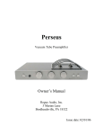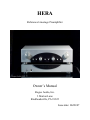
1
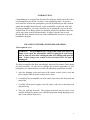
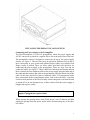
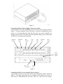
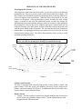
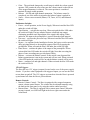
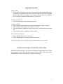
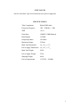
HERA
Reference Linestage Preamplifier
Owner’s Manual
Rogue Audio, Inc.
3 Marian Lane
Brodheadsville, PA 18322
Issue date: 06/08/07
TABLE OF CONTENTS
1) Introduction
2
2) Unpacking the Hera Preamplifier
2
3) Installing the Hera into your system
3
4) Operation of the Hera Peamplifier
6
5) Troubleshooting
8
6) Registration of your Hera
8
8) Fuse values
9
9) Specifications
9
10) Product Registration and Warranty
10
1
INTRODUCTION
Congratulations on your purchase decision! We at Rogue Audio truly believe that
our preamplifiers provide the “smartest” value in high-end audio. If you have
never owned a vacuum tube preamplifier you will be thrilled by the silky-smooth
sound and incredible detail that only a tube preamplifier can provide. And with
the Hera preamplifier, you can be sure that you are getting the very best in tube
amplification. We at Rogue Audio are extremely proud of our products and want
you to enjoy them to their fullest potential. So please, take the time to read
through this short manual so that you can be confident that you have set up your
preamplifier properly.
UNPACKING THE HERA POWER PREAMPLIFIER
Tools required: none
WARNING - This preamplifier uses voltages that could cause injury or
death. Never open the preamplifier while it is plugged in, and always
wait at least one hour after turning the unit off to unplug and open the
unit. Lethal voltages can remain in the electronics after the unit is
unplugged.
The Hera preamplifier has been painstakingly inspected for cosmetic flaws during
and after assembly. In order not to damage the cosmetic appearance of your
preamplifier it is important that you follow the unpacking instructions carefully.
1. Open the shipping carton and remove the remote control, power cord and
power supply cables from the corners of the carton.
2. Carefully lift the preamplifier out of the carton, and remove the foam pads and
plastic bag.
3. Carefully lift the power supply out of the carton, and remove the foam pads
and plastic bag.
4. Save the packing materials. The packing materials and box have been
carefully designed to protect your valuable equipment during shipping so you
don’t want to throw them away.
2
Figure 1.
INSTALLING THE HERA INTO YOUR SYSTEM
Connecting the Power Supply to the Preamplifier
The Hera Preamplifier is a two box preamplifier, where the power supply and
AC/DC conversion is placed in a separate box to lower the noise floor of the unit.
The preamplifier chassis is designed to sit directly on top of the power supply
chassis, see Figure 1. The two boxes may be placed on different racks if this is
more convenient in your system and optional longer cables are available from
Rogue Audio if needed. There are three cables provided with the Hera for
connecting the power supply to the preamplifier. These are four, five and six
conductor cables. See Figure 2. These cables have both male and female ends on
them. Connect the four conductor cable to the power supply using the male end of
the cable and then connect the cable to the preamplifer using the female end of the
cable. Do the same for the five and six conductor cables. It is important to make
these connections before connecting the power cord to the wall outlet. Note that
certain critical portions of the Hera circuitry remain energized even when the unit
is turned off so do not disconnect any of these cables while the power supply is
plugged into a power outlet.
Warning – Never disconnect any of the three cables while the power
supply is plugged into a power outlet.
When moving the preamp always turn off the power, wait 15 minutes and then
unplug the preamp from the power outlet before disconnecting any of the three
rear cables.
3
Figure 2
Connecting the Hera Power Supply to the power outlet:
Connect the IEC end of the detachable power cord to the Power Supply, shown in
Figure 3. Plug the opposite end of the power cord into an appropriate power
outlet. It is recommended that both the Hera and your power amplifier are
plugged into the same wall outlet if possible (perhaps using a power outlet strip)
in order to avoid creating a ground loop.
Balanced
Outputs
Balanced
Input
RCA
Outputs
Unity
Gain
Tape
Loop
Processor
Loop
RCA
Inputs
Power
Supply
Cables
IEC
Power Plug
Main
Fuse
Figure 3
Connecting the Hera to two channel (Stereo) sources:
Connections are made on the rear panel of the preamplifier and are shown in
Figure 3. The input connections for two channel source material are made via
RCA Jacks or XLR Balanced Connectors. There are 4 RCA line level inputs:
4
Phono (for an external phono preamp), CD, Tuner, and AUX 1. There is also one
pair of Balanced XLR inputs.
Connecting the Hera to multi channel sources using the Unity Gain Input:
The Hera features a unity gain bypass allowing you to integrate your two channel
music systems into a multichannel home theater system. This conveniently
enables you to share speakers and amps between systems without switching
interconnect or speaker cables. In this configuration the Hera is then used with
two channel sources such as CD Players, turntables, tuners etc, while a separate
processor or multi channel receiver is used with multichannel sources such as
DVD movies. Simply connect the left and right front outputs from your processor
to the unity gain inputs on the Hera. These inputs route the home theater signal
directly to the power amp completely bypassing the active circuitry in the Hera.
To activate this unity gain input, the bypass switch on the front of the preamplifier
must be pushed in (see Figure 3). Once this switch is on, all other inputs are
deactivated and the preamplifier is in bypass mode. Note that if the preamplifier is
turned off it automatically goes into bypass mode.
Connecting an audio processor to the Hera:
The Hera features a processor loop which allows processors (equalizer, room
correction, bass enhancement, etc.. ) to be used. There are two sets of RCA jacks
on the rear of the preamp for connecting to/from a processor. When the processor
button is pushed in a blue LED below the button will light indicating that the
source signal is going through the processor. With the button out the signal
bypasses the processor. Note that if no processor is connected and the button is
pushed in then the signal is interrupted and there will be no output from the
preamplifier.
Connecting a tape or CD recorder to the Hera:
The Hera features a buffered tape loop and tape monitor for recording from other
sources and for monitoring the recording as it is being made. The buffered tape
output prevents “loading down” of the preamp by the recording equipment thus
providing a higher level of fidelity in the recording process as well as the
monitored playback. Connect the output jacks from the recording device to the
“Tape In” jacks on the back of the Hera. Connect the “Tape Out” jacks on the
Hera to the input jacks of the recording device. Note that if the Tape Monitor
button is pushed in on the Hera that the source will be the output from the
recording device.
Connecting the Hera to the power amplifier:
There are two RCA outputs and two Balanced XLR outputs. These are used to
connect the Preamplifier to the Power Amplifier in your system. Note that the
output in balanced mode is 3dB higher than for single ended mode.
Connecting a subwoofer to the Hera:
A second set of both RCA and XLR outputs are provided that can be used for
connecting a subwoofer to the Hera. The signal to these outputs is identical to the
signal going to the power amp and varies with the volume control. Note that these
outputs can also be used for biamping or running a second power amp located
elsewhere.
5
OPERATION OF THE PREAMPLIFIER
Powering up the System:
After all proper connections have been made, you are now ready to turn the Hera
preamplifier on. The power on/off switch is on the front of the power supply. The
Hera employs an automated sequential soft-starting mode to prolong tube life as
well as to suppress turn-on transients. When the unit is first turned on, the tube
heaters are energized. After approximately twenty seconds, the high voltage
supply is turned on and after and additional twenty seconds the outputs are
disconnected from ground and the preamp is ready for operation. After turning on
the preamplifier, turn on the power amplifier and source material and you are
ready for listening. Note that critical portions of the Hera remain energized even
with the power button in the off position. The first time that the Hera is turned on
(and anytime it is unplugged from the power outlet) it is best to let it idle for a few
minutes before playing music. This allows these portions of the circuitry to reach
optimum operating parameters.
NOTE - This unit will not play for approximately 40-60 seconds after
power on while the preamp goes through its sequential start-up.
Selector
Switch
Tape
Monitor
Processor
Gain
Switch
Bypass
Phase
Invert
Balance
Knob
Balance
Switch
Mono
Volume
Control
Mute
LED
Power
Switch
Figure 4
Switches and Controls:
The Hera is equipped with extremely high quality volume, balance, source, and
gain switches. It also has power, tape monitor, processor, bypass, phase invert,
balance, and mono buttons. See Figure 4. In addition the Hera is provided with a
remote volume control and mute feature.
Knob Controls
• Volume - The Hera employs a proprietary stepped attenuator that is connected
to a DC motor via a miniature slipper clutch. Volume adjustments are made
in approximately 2dB increments.
6
•
•
•
Gain – The gain knob changes the overall range in which the volume control
operates. This permits the user to fine tune the volume control so that full use
of the stepped attenuator is achieved. The center position is considered
nominal for single ended operation.
Balance - full left and right channel attenuation. The balance control is
completely out of the audio circuit unless the balance button is pushed in.
Source – selects source material (Phono, CD, Tuner, AUX1, and Balanced
inputs)
Pushbutton Switches
• Power – on/off operation, on the Power Supply. When activated the blue LED
under the switch will light.
• Tape Monitor - activates the tape loop. When activated the blue LED under
the switch will light. The tape monitor features a buffered tape output
eliminating potential sonic degradation of the signal while taping. When
pushed in, the input to the preamplifier is sourced from the taped material.
• Processor - activates the processor loop. When activated the blue LED under
the switch will light.
• Bypass – As explained in the Installation Section, the bypass switch routes the
unity gain input directly to the amplifier ouputs effectively bypassing the
preamplifier. When activated the blue LED under the switch will light.
• Phase Invert – switches the phase of the output of the preamplifier. When
activated the blue LED under the switch will light. Note that correcting the
phase of some recordings may provide better fidelity.
• Balance – activates the balance control. If this switch is not depressed the
balance potentiometer is not in the system and will not work. When activated
a blue LED under the switch will be on and the balance control will be active
• Mono – combines left and right channels. When activated the blue LED under
the switch will be lit.
12Volt Triggers:
The Hera has two 12V trigger (outputs) located on the rear of the power supply
chassis. If you have other equipment with triggered inputs you can use the Hera
to turn them on and off. The 12V triggers are turned on when the Hera is powered
up and turned off when the Hera is powered down.
Remote Controls
• Remote Volume Control – The Hera is equipped with a stepped attenuator
remote volume control feature. The volume may be adjusted manually using
the knob on the front panel, or by using the remote control provided.
• Remote Mute - The Hera is equipped with a remote mute control. When the
preamp is muted, a red LED will light in the lower right corner under the
volme knob.
7
TROUBLESHOOTING
Speaker Hum
• If hum can be heard from more than a few inches from the loudspeaker, there
is probably a ground loop. Be sure to have the amp and all sources plugged
into the same outlet if possible. If this fails to cure the hum, call customer
service at Rogue Audio for further advice 570-992-9901.
Unit does not turn on
• Check that the power cord connection is secure
Unit does not play
• Ensure that the interconnects are connected to the proper input or output.
• Ensure that the interconnects are connected securely.
• Processor button is pushed in with no processor or with the processor turned
off.
• Tape monitor button is pushed in with no signal.
One channel does not play
• Ensure that the balance pot is centered.
• Ensure that the tubes are seated correctly and securely
For further problems, please call Rogue Audio Technical Support at 570-992-9901.
OWNER AND WARRANTY REGISTRATION FORM
Included with this manual is an Owner and Warranty Registration Form. Please
take a minute to fill out this card and return it to Rogue Audio. This card must be
returned within 30 days of purchase to validate the warranty.
8
FUSE VALUES
One 5A slow Blow Type Fuse located on rear of power supply box
SPECIFICATIONS
Tube Complement
Eight 6H30P tubes
Frequency Response
1Hz – 250KHz +/- 3dB
THD
<0.1%
Gain Stage
12dB SE, 15dB Balanced
Rated Output
1V RMS
Output impedance
150 Ohms
Maximum Output
25 Peak
Main Unit Dimensions
18_ x 15_ x 31/2
Power Supply Dimensions 18_ x 15_ x 51/2
Main Unit Weight
28 Lb
Power Supply Weight
25 Lb
Shipping Weight
60 Lb
Power Requirements
115/230V – 50/60Hz
9
LIMITED WARRANTY
Warranty Period
This product has been manufactured under the highest standards of quality and workmanship. Rogue Audio
Inc. (hereinafter “Rogue Audio”) warrants this product against defects in material or workmanship as
follows:
With the exception of vacuum tubes, Rogue Audio warrants to the original purchaser of this product all
parts of this product against defects in material and workmanship for a period of three years from the date of
retail purchase. Rogue Audio warrants the vacuum tubes for a period of six months from the date of retail
purchase. Any defective parts will be replaced free of charge, excluding shipping and handling.
Proof of purchase in the form of a bill of sale or recited invoice which indicates that the product is within
the warranty period must be presented to obtain warranty service. Rogue Audio suggests that the purchaser
retain the dealer’s bill of sale as evidence of the date of retail purchase.
What’s Not Covered
This warranty does not cover cosmetic damage or any damage that results from product misuse, product
abuse, installation error, connection to an improper voltage supply, accident, improper maintenance,
alterations, modifications not authorized in writing by Rogue Audio, lightening, power surges, or acts of God.
Use of any other than Rogue Audio factory parts may void this warranty.
This warranty does not cover the cost of parts and labor which would be otherwise provided without charge
under this warranty, obtained from any source other than Rogue Audio.
This warranty applies only to consumer use of this product and does not cover any product that is used in
any trade or business, or in an industrial or commercial application.
This warranty applies only to the original purchaser of this product when purchased from an
Authorized Rogue Audio dealer.
This warranty is valid only in the United States.
YOUR RIGHTS
ROGUE AUDIO LIMITS ITS OBLIGATIONS UNDER ANY IMPLIED WARRANTIES UNDER STATE
LAWS TO A PERIOD NOT TO EXCEED THE WARRANTY PERIOD. SOME STATES DO NOT
ALLOW LIMITATIONS ON HOW LONG AN IMPLIED WARRANTY LASTS, AND SOME STATES
DO NOT ALLOW THE EXCLUSION OR LIMITATION OF INCIDENTAL OR CONSEQUENTIAL
DAMAGES, SO THE ABOVE LIMITATIONS OR EXCLUSIONS MAY NOT APPLY TO YOU. THIS
WARRANTY GIVES YOU SPECIFIC LEGAL RIGHTS, AND YOU MAY HAVE OTHER
RIGHTS WHICH MAY VARY FROM STATE TO STATE.
To Obtain Service
To obtain service, you must contact Rogue Audio and obtain a return authorization number. The product
must be delivered to Rogue Audio in its original packaging prepaid at the following address:
Rogue Audio Inc.
3 Marian Lane
Brodheadsville, PA 18322
10