1
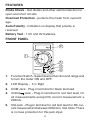
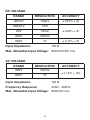
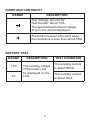
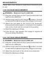
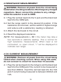
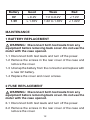
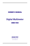
USER'S MANUAL
Digital Multimeter
DMR-1100A
CIRCUIT-TEST ELECTRONICS
www.circuittest.com
INTRODUCTION
Your Circuit-Test DMR-1100A Digital Multimeter incorporates the latest technology to provide you with a feature
packed instrument. With it you can measure a wide range
of voltages, current and resistance in the lab, shop, car and
home. This product has been designed for the electrician,
technician and hobbyist.
SAFETY INFORMATION
This meter conforms to IEC-61010 for Category I 600V and
pollution degree 2. This meter is designed for indoor use
only and proper guidelines must be followed for personal and
product safety. Per IEC1010 over installation category, equipment of overvoltage Category I is equipment for connection
to circuits in which measures are taken to limit the transient
overvoltages to an appropriate low level. Examples include
protected electronic circuits. Note: Do not use this meter for
measurements within overvoltage Category II, III and IV.
SAFETY SYMBOLS
This symbol adjacent to another symbol, terminal
or operating device indicates that the operator must
refer to an explanation in the Operating Instructions
to avoid personal injury or damage to the meter.
This symbol adjacent to one or more terminals identifies them as being associated with ranges that may,
in normal use, be subjected to particularly hazardous
voltages. For maximum safety, the meter and its test
leads should not be handled when these terminals
are energized.
2
This symbol advises the user that the terminal(s)
so marked must not be connected to a circuit point
at which the voltage with respect to earth ground
exceeds (in this case) 600 VAC or VDC.
WARNING
1. Set the function switch correctly before making any
measurements.
2. Do not operate the unit unless the case is completely
closed.
3. Disconnect test leads from equipment before removing
the battery.
4. Never connect unit to AC or DC powered circuits when
function switch is set to Ω, diode check or continuity.
5. To safeguard against electrical shock or damage to
instrument, never connect to more than 600V DC or
600V AC between input jacks and ground.
6. Always inspect the instrument, test leads and other
accessories for damage prior to use.
7. Read this instruction manual carefully and completely
before using.
SAFETY PRECAUTIONS
High voltage AC and DC circuits are dangerous. Always
consider circuits to be energized. Never assume any equipment is de-energized. Lack of caution or poor safety practices
can be very dangerous and/or lethal.
3
FEATURES
Diode Check - test diodes and other semiconductors for
open and short circuits.
Overload Protection - protects the meter from overvoltage.
Auto-Polarity - indication on display that polarity is
reversed.
Battery Test - 1.5V and 9V batteries.
FRONT PANEL
2
1
20
V
200
600
OFF
600
~
V
200
2000
μ
20
m
2000
m
A
200
m
200
m
2000
k
200
k
10A
Ω
1.5V
20k
BATT.
2000
9V
200
CIRCUIT-TEST
10A
UNFUSED 10A MAX
For 10 sec. MAX
every 15 min.
VΩ mA
DMR-1100A
DIGITAL MULTIMETER
FUSED
200mA 250V ~ MAX
600V ~ MAX
COM
CAT I
600V
5
4
3
1. Function Switch - Select desired function and range and
to turn the meter ON and OFF.
2. LCD Display - 3 ½ Digit
3. COM Jack - Plug-in terminal for black test lead
4. VΩmA Jack - Plug-in terminal for red test lead, for
all measurements except DC current measurement ≥
200mA.
5. 10A Jack - Plug-in terminal for red test lead for DC current measurement between 200mA to 10A. Note: There
is no fuse protection for this jack input.
4
SPECIFICATIONS
a. GENERAL
Display:
3.5 digit, 0.5" (12mm) H LCD
Polarity:
Automatic, minus (-) sign indicates negative polarity
Ranging:
Over range:
Low Battery:
Manual ranging
"1" is displayed
"
" or "BAT" indicates low battery
Input Impedance: 1M Ω (DCV/ACV)
Sampling Rate:
About 2 to 3 times/sec.
Storage Temp.: -10 to 50oC
Power Source:
1 - 9V Battery
Operation Temp.: 0 to 40oC
Fuse:
Dimensions:
Weight:
GMA 250mA/250V
70(W) x 127(H) x 25(D)mm
170g (including battery)
b. TECHNICAL
Note: Accuracy is stated at 65°F to 83°F (18°C to 28°C)
and less than 75% RH.
Accuracy is:
± ([ % of reading] + [Number of least significant digits])
5
DC VOLTAGE
RANGE
RESOLUTION
ACCURACY
200mV
100μV
± (0.5% + 5)
2000mV
1mV
20V
10mV
200V
100mV
600V
1V
Input Impedance: ± (0.8% + 5)
± (1.0% + 5)
1M Ω
Max. Allowable Input Voltage: 600V DC/AC rms
AC VOLTAGE
RANGE
RESOLUTION
200V
100mV
600V
1V
Input Impedance: ACCURACY
± (1.2% + 10)
1M Ω
Frequency Response:
45Hz - 400Hz
Max. Allowable Input Voltage: 600V AC rms
6
DC CURRENT
RANGE
RESOLUTION
2000μA
1μA
20mA
10μA
200mA
100μA
± (1.2% + 5)
10A
10mA
± (2.0% + 5)
Overload Protection:
ACCURACY
± (1.0% + 5)
Fuse, 250mA/250V, Fast (for the "VΩ
inputs only)
mA" terminal's
There is no fuse protection for the "10A" terminal's
inputs.
Max. Allowable Input Current: 10A
(For inputs > 2A : measurement duration < 10 secs,
interval > 15 minutes)
RESISTANCE
RANGE
RESOLUTION
ACCURACY
200Ω
0.1Ω
± (1.2% + 5)
2000Ω
1Ω
20kΩ
10Ω
200kΩ
100Ω
2000kΩ
1kΩ
Max. Open Circuit Voltage:
7
± (1.0% + 5)
± (1.2% + 5)
about 3V
DIODE AND CONTINUITY
RANGE
DESCRIPTION
Test Voltage: about 2.8V
Test Current: about 1mA
The approximate forward voltage
drop in mV will be displayed.
The built-in buzzer will sound when
the resistance is less than about 50Ω
BATTERY TEST
RANGE
DESCRIPTION
1.5V
The working voltage
of the battery will
be displayed on the
LCD.
9V
8
TEST CONDITION
The working current
is about 20mA.
The working current
is about 5mA.
MEASUREMENTS
Please take a few minutes to read these instructions prior
to use.
1 DC VOLTAGE MEASUREMENT
WARNING: Maximum input is 600V DC.
1-1Plug the red test lead into the V jack and the black test
lead into the COM jack.
1-2Set the range switch to the desired position. It is best
to start with the highest range if the voltage is not known.
1-3Attach the test leads to the circuit to be measured.
Ensure that the black lead is connected to the negative
side of the circuit and the red lead to the positive.
1-4Read the displayed voltage.
1-5If the minus(-) sign appears the voltage is negative at
the point being measured.
2 AC VOLTAGE MEASUREMENT
WARNING: Maximum input is 600V AC.
2-1Plug the red test lead into the V jack and the black test
lead into the COM jack.
2-2Set the range switch to the desired position. It is best
to start with the highest range if the voltage is not known.
2-3Attach the test leads to the circuit to be measured.
2-4Read the displayed voltage.
9
3 RESISTANCE MEASUREMENT
WARNING: Remove all power from the circuit being
tested when checking resistance. Discharge any charged
capacitors. Never connect the probes to any voltage
while the selector is set to OHM.
3-1Plug the red test lead into the V jack and the black test
lead into the COM jack.
3-2Set the range switch to the desired Ω position. If the
resistance is not known, set the switch to highest range
and reduce until a satisfactory reading is obtained.
3-3Attach the test leads to the circuit.
3-4Read the displayed resistance.
NOTE: For measurements > 1M Ω the meter may take a
few seconds to stabilize reading. This is normal for
high resistance measurements. When input is not
connected, i.e. open circuit, "1" will be displayed to
indicate over range.
4 DC CURRENT MEASUREMENT
WARNING: Remove all power from the circuit being
tested when checking current. When using 10A scale,
do not connect to circuit for more than 10 seconds.
4-1Plug the red test lead into the mA jack and the black test
lead into the COM jack if the current to be measured is
less than 200mA. Insert the red test lead into the 10A
jack if current being measured is between 200mA and
10A.
10
4-2Set the range switch to one of the current ranges. If
you are unsure of the amount of current being measured
set switch to the highest reading and reduce until a
satisfactory reading is obtained.
4-3Remove power from the circuit that is to be measured.
Open up the circuit and connect the black lead to the
negative side and the red lead to the positive side of
the circuit so that the test leads are in series with the
load to be measured.
4-4Apply power to the circuit.
4-5Read the displayed current.
NOTE: If changing range switch to or from the 10A position
first disconnect power and test leads from the circuit
being tested. Repeat the above steps using the correct
input jack and range switch position.
5 DIODE TEST
WARNING: Remove all power from the circuit being
tested when using the diode check. Discharge any
charged capacitors. Never connect the probes to any
voltage while the selector is set to .
5-1Plug the red test lead into the V jack and the black test
lead into the COM jack.
5-2Set the function switch to
11
.
5-3 Connect the red test lead to the anode and the black test
lead to the cathode of the diode to be tested.
5-4 The approximate forward voltage drop of the diode will
be displayed in mV. If the connection is reversed “1”
will be displayed.
6 CONTINUITY TEST
WARNING: Remove all power from the circuit being
tested when checking continuity. Discharge any charged
capacitors. Never connect the probes to any voltage
while the selector is set to .
6-1 Plug the black test lead into the COM jack and red test
lead into the V jack
6-2 Set the function switch to
.
6-3 Connect the probes across the circuit to be measured.
6-4 If the resistance is lower than about 50Ω, the buzzer
will sound.
7 BATTERY TEST
7-1 Plug the black test lead into the COM jack and red test
lead into the V jack
7-2 Set the function switch to desired BATT range position
(1.5V or 9V).
7-3 Connect the test leads to the two terminals of the battery
to be measured and note the reading.
12
Battery
Good
Weak
Bad
9V
> 8.2V
7.2 to 8.2V
< 7.2V
1.5V
> 1.35V
1.22 to 1.35V
< 1.22V
MAINTENANCE
1 BATTERY REPLACEMENT
WARNING: Disconnect both test leads from any
equipment before removing back cover. Do not use the
meter with the case opened.
1-1Disconnect both test leads and turn off the power.
1-2Remove the screws in the rear cover of the case and
remove the cover.
1-3Unsnap the battery from the connector and replace with
a new 9V battery.
1-4Replace the cover and cover screws.
2 FUSE REPLACEMENT
WARNING: Disconnect both test leads from any
equipment before removing back cover. Do not use the
meter with the case opened.
2-1Disconnect both test leads and turn off the power.
2-2Remove the screws in the rear cover of the case and
remove the cover.
13
2-3Replace the blown fuse with a GMA 250mA/250V fuse.
Do not use a fuse which has a higher rated value than
specified or try to bypass the fuse.
2-4Replace the cover and cover screws.
LIMITED WARRANTY
Circuit-Test Electronics warrants to the original purchaser
that this product be free of defect in material or workmanship
for a period of 2 years from the date of purchase.
Any product which has been subjected to misuse or accidental damage is excluded from the warranty. Except as
stated above, Circuit-Test Electronics makes no promises or
warranties either expressed or implied including warranties
of merchantability or the fitness for any particular purpose.
M-DMR-1100A / 07R13
14