1
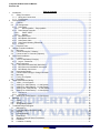
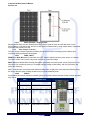
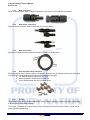
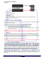
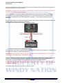
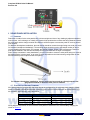
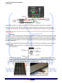
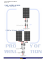
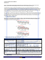
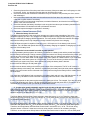
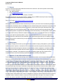
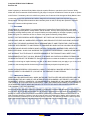
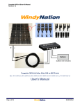
Complete Off-Grid Solar Kit Manual
Revision 2.0
windynation
Complete Off-Grid Solar Kits
30 to 400 Watts
Installation Manual
Page 1 of 21
windynation
03/31/2014
Complete Off-Grid Solar Kit Manual
Revision 2.0
1
2
3
4
5
6
7
Table of Contents
Introduction ...................................................................................................................................................... 3
1.1
Safety Precautions .................................................................................................................................. 3
1.1.1 Wiring and Connections ...................................................................................................................... 3
1.1.2 Environment ........................................................................................................................................ 3
Product Overview ............................................................................................................................................. 3
2.1
Features .................................................................................................................................................. 3
2.2
Kit Components ....................................................................................................................................... 3
2.2.1 Solar Panel .......................................................................................................................................... 3
2.2.1.1
Monocrystalline – Polycrystalline ............................................................................................... 4
2.2.2 Solar Charge Controller ....................................................................................................................... 4
2.2.2.1
PWM – MPPT ............................................................................................................................. 4
2.2.2.2
Models ........................................................................................................................................ 4
2.2.3 MC4 Connectors.................................................................................................................................. 5
2.2.4 MC4 Branch Connectors ..................................................................................................................... 5
2.2.5 Solar Panel Cable................................................................................................................................ 5
2.2.6 Solar Panel Mounting Z-Brackets........................................................................................................ 5
2.2.7 Inverter ................................................................................................................................................ 5
2.3
Required Tools ........................................................................................................................................ 6
Charge Controller Installation .......................................................................................................................... 6
3.1
Mounting .................................................................................................................................................. 6
3.2
Connect Controller To Battery ................................................................................................................. 6
3.3
Connect Load To Controller (Optional) ................................................................................................... 7
Solar Panel Installation .................................................................................................................................... 8
4.1
Location ................................................................................................................................................... 8
4.2
12 or 24 Volt Battery Charging ................................................................................................................ 8
4.2.1 Layout - Placement.............................................................................................................................. 9
4.3
MC4 Connectors...................................................................................................................................... 9
4.3.1 MC4 Connector Assembly Instructions ............................................................................................... 9
4.3.2 MC4 Connector Installation Instructions.............................................................................................. 9
4.3.3 MC4 Branch Connectors ..................................................................................................................... 9
4.4
Interconnect Panels ............................................................................................................................... 10
4.5
Connect Solar Panel(s) to Charge Controller ........................................................................................ 10
4.6
Mounting ................................................................................................................................................ 11
4.7
Fusing Your System .............................................................................................................................. 12
4.8
Grounding .............................................................................................................................................. 12
Panel Placement and Wiring .......................................................................................................................... 13
5.1
100W – 12 Volt System ......................................................................................................................... 13
5.2
200W (Two 100W Panels) – 12 Volt System ........................................................................................ 13
5.3
200W (Two 100W Panels) – 24 Volt System ........................................................................................ 14
5.4
300W (Three 100W Panels) – 12 Volt System ..................................................................................... 15
5.5
400W (Four 100W Panels) – 12 Volt System ....................................................................................... 16
5.5.1 1x4 Layout ......................................................................................................................................... 16
5.5.2 2x2 Layout ......................................................................................................................................... 16
5.6
400W (Four 100W Panels) – 24 Volt System ....................................................................................... 17
Batteries ......................................................................................................................................................... 17
6.1
Types ..................................................................................................................................................... 17
6.2
Sizing ..................................................................................................................................................... 17
6.3
Wiring Battery Banks ............................................................................................................................. 18
Troubleshooting and Support......................................................................................................................... 18
7.1
Maintenance .......................................................................................................................................... 18
7.2
Frequently Asked Questions (FAQ) ...................................................................................................... 19
7.3
Support .................................................................................................................................................. 20
7.1
Limited Warranty ................................................................................................................................... 20
7.2
Restrictions ............................................................................................................................................ 20
7.3
Warranty Claims & Return Procedures ................................................................................................. 20
7.4
Disclaimer .............................................................................................................................................. 21
7.5
Limitation of Liability .............................................................................................................................. 21
Page 2 of 21
windynation
03/31/2014
Complete Off-Grid Solar Kit Manual
Revision 2.0
1 INTRODUCTION
Congratulations on purchasing a high quality renewable energy product where building your own off-grid solar
system has never been easier. Although installation is quick and professional using the materials included in
your kit, it is important to read this manual and understand all the mechanical and electrical requirements prior
to beginning installation. If there are questions or concerns of any sort, please contact us at
[email protected] for further assistance.
The installer must be familiar and conform to all the safety precautions cited in this manual as well as any local
jurisdictions that must be adhered to.
1.1 SAFETY PRECAUTIONS
CAUTION:
Working with and installing electrical equipment is dangerous. Potential hazards include, but are not limited to,
electrocution and electrical fires. Always consult a licensed electrician when installing any electrical equipment.
CAUTION:
When solar panels are placed in sunlight or other light sources, they produce electrical energy and a voltage will
appear on the output terminals. To avoid a shock hazard, keep the panel covered with a dark material during
installation and avoid contact with the output terminals. Before handling the solar panel, test the voltage output
of the solar panel with a voltmeter to confirm it is not outputting voltage.
1.1.1
Wiring and Connections
• Wiring size and installation must comply with the National Electrical Code (NEC).
• Observe correct polarity with all inter-connections between the solar panel, charge controller, and the
battery. Reverse polarity may cause damage.
• Make sure all wire connections are tight and secure, loose connections may cause sparks and
intermittent behavior.
1.1.2
Environment
• Do not perform installation in the presence of any flammable materials.
• Make sure you work in a well-ventilated area
• Use properly insulated tools and remove metal items such as rings, bracelets, and watches.
2 PRODUCT OVERVIEW
Windy Nation offers many varieties of preconfigured off-grid solar kits designed to be modular and easily
expandable. Each kit is capable of a wide variety of power production needs from simply trickle charging
batteries to fully supporting the power needs of a cabin or RV.
2.1 FEATURES
•
•
•
•
Auxiliary power for RV’s and boats. Popular with commercial RV retrofitters
Great for camping or remote cabins. Power devices in remote back country locations
Easy way to provide power for sheds, light poles and gates without the need for trenching and laying
cables
Two or more panels can provide back-up power for critical appliances like a refrigerator during a power
outage.
2.2 KIT COMPONENTS
IMPORTANT: Not all of the components listed are included with each kit. The quantity and exact model of each
item will vary depending on the kit ordered.
2.2.1
Solar Panel
The solar panel is a set of solar photovoltaic modules that generate electricity and are available in powers of
30W, 60W, and 100W; with either Monocrystalline or polycrystalline solar cells. For kits sized 200W and larger,
the use of multiple 100W panels is utilized.
Page 3 of 21
windynation
03/31/2014
Complete Off-Grid Solar Kit Manual
Revision 2.0
2.2.1.1
Monocrystalline – Polycrystalline
Monocrystalline solar cells are manufactured using a single crystal of silicon and are dark black in color.
Polycrystalline, on the other hand, are blue in color and are manufactured by using multiple silicon crystals that
are melted and poured into a cast.
2.2.2
Solar Charge Controller
The solar charge controller regulates the battery charge and prevents overcharging of the batteries thus
increasing battery performance and lifespan.
2.2.2.1
PWM – MPPT
PWM (Pulse Width Modulation) Controllers use a FET switch to rapidly connect a power source, to a battery.
The switch "opens" and "closes" many times a second, to control the charge.
MPPT (Maximum Power Point Tracking) Controllers dynamically convert the power source (PV panels) via an
efficient DC-DC conversion process, to a suitable charging voltage for the battery, with very low losses, and
about 95% efficiency.
MPPT controllers are more efficient than PWM and will produce roughly 20% more power than PWM by using
the Vmp of the solar panel (Voltage at Max Power) to create additional power.
2.2.2.2
Models
Windy Nation has several controllers available; please consult the individual manuals for the controller provided
with your kit.
SKU
DESCRIPTION
1
CHC-1224-10
10A PWM Solar Controller
2
CHC-1224-30
30A PWM Solar Controller
3
4
Page 4 of 21
CHC-TRMX-40 TrakMax 40 MPPT Controller
CHC-LCD-30
P30L 30A LCD Controller
windynation
03/31/2014
Complete Off-Grid Solar Kit Manual
Revision 2.0
2.2.3
MC4 Connectors
Single-contact connector used to connect solar panels; See Section 4.3 for additional information
2.2.4
MC4 Branch Connectors
Splitter/Combiner connector used to easily interconnect solar panels
2.2.5
Solar Panel Cable
Assembly of copper electrical conductors available in 12AWG or 10AWG sizes
2.2.6
Solar Panel Mounting Z-Brackets
Mounting brackets used to secure panel to a flat surface. There are four (4) brackets used for each solar panel
and include the following fasteners used to secure the bracket to the panel:
a. 1/4" diameter stainless steel bolts (1/2" long)
b. Stainless Steel flat washers and lock washers
c. K-Lock stainless steel nuts (will not vibrate loose)
2.2.7
Inverter
An electronic device that converts the battery DC voltage (Direct Current) provided from the solar panel/battery
to an AC voltage (Alternating Current).
The inverter, if included, will connect directly to the 12V battery and will provide three 120VAC outlets used to
power typical household items.
Page 5 of 21
windynation
03/31/2014
Complete Off-Grid Solar Kit Manual
Revision 2.0
2.3 REQUIRED TOOLS
•
•
•
•
•
•
•
Two adjustable wrenches
Wire crimping tool
Wire stripper
Philips head screwdriver
Bolt to secure Z-Bracket to mounting surface (4x per panel); e.g.: lag bolt, carriage bolt, etc.
Batteries (Deep Cycle preferred)
Fuses
3 CHARGE CONTROLLER INSTALLATION
NOTE: The charge controller you receive depends on the kit ordered. Please refer to the controller instructions
specific to the model you received.
Insure all terminating connections are clean and tight to prevent arcing and overheating.
The controller must be installed in an area that satisfies all of the following conditions:
1.
Dry: Avoid any location where water can contact the controller
2.
Cool: Ambient air temperature between 30°F and 105°F (0°C and 40°C)
3.
Ventilated: Allow at least 2 in (50 mm) of clearance above and below and at least 1 in (25 mm) on
each side for proper air flow.
CAUTION: All electronic circuits may be damaged by static electricity. To minimize the likelihood of electrostatic
damage, discharge yourself by touching an electrical ground (e.g.: copper pipe) prior to handling the unit.
3.1 MOUNTING
Mounting is optional but for best results, locate the charge controller as close as possible to the batteries and
the batteries and charge controller as close to the panels as practical. The controller can be mounted on a
vertical or horizontal surface. Be sure to orient the controller so that any open end of the controller (if applicable)
is at the top. This will prevent foreign material from settling into the unit.
Securely fasten the controller to ensure it cannot slide in any direction.
IMPORTANT: Loose connectors result in excessive voltage drop and may cause over heated wires and melted
insulation, which can lead to solar system failure and electrical fires.
3.2 CONNECT CONTROLLER TO BATTERY
The wire included in your kit is to be used primarily to connect the solar panels to the controller. It is important to
adequately size your battery cable according to your system size, taking into account any future expansion that
may be implemented. For additional information regarding wire size, please refer to the Windy Nation website or
contact us directly. Two lengths of cable will be required, a positive (+) and a negative (-). It is recommended to
identify each cable or use a different colored cable for each connection (eg: black and red). Connect the wire
designated as positive (+), usually red, to the BATTERY terminals on the charge controller labeled ‘BAT +’ and
tighten the terminal with a screwdriver. Connect the wire designated as negative (-), usually black, to the
BATTERY terminals on the charge controller labeled ‘BAT -’ and tighten the terminal with a screwdriver.
NOTE: The polarity should be identified on the screw-down terminals of the charge controller; however, the
naming convention of the terminals may differ slightly, depending on the model of the solar controller that came
with your Kit.
Page 6 of 21
windynation
03/31/2014
Complete Off-Grid Solar Kit Manual
Revision 2.0
Once the connections are made to the battery terminals on the charge controller, make sure the battery post
terminals are clean and free from corrosion.
IMPORTANT: A properly sized fuse needs to be placed in the positive wire connecting the charge controller to
the battery; See Section 4.4.4 for assistance.
It is recommended to use a battery cable lug appropriately sized to fit the post of your battery. Connect the
remaining loose end of the wire designated as positive (+), to the positive post/terminal of the BATTERY.
Connect the remaining loose end of wire designated as negative (-), to the negative post/terminal of the
BATTERY.
As soon as the battery is connected to the charge controller, the controller will power automatically and should
indicate a battery voltage is applied (eg: green LED).
The diagram below shows the connection for controller to battery
3.3 CONNECT LOAD TO CONTROLLER (OPTIONAL)
The connection of a DC load is optional and most applications will not utilize this connection. It is designed to be
used with 12VDC lighting or small 12VDC appliances.
CAUTION: A Power Inverter (if used) should never be connected to the LOAD terminals of the controller. The
inverter will be connected directly to the BATTERY posts.
If desired, connect your small 12VDC light or appliance to the LOAD terminals on the controller. For most light
bulbs the polarity doesn’t matter. However, if your Bulb or small appliance has Positive (+) and Negative (-)
leads, make sure to connect them to the corresponding terminals on the charge controller.
IMPORTANT: A properly sized fuse needs to be placed in the positive wire connecting the load (e.g. light, etc)
to the charge controller.
The diagram below shows the connection for controller to load
Page 7 of 21
windynation
03/31/2014
Complete Off-Grid Solar Kit Manual
Revision 2.0
4 SOLAR PANEL INSTALLATION
4.1 LOCATION
Determine a location for the solar panel that is in direct sunlight and clear of any shading by adjacent obstacles
such as trees, roof overhangs, etc. Ideally, the panels will be positioned to minimize the wiring distance between
the solar panel and the charge controller and will have sufficient space to access the panel for servicing should
it be required.
For Northern Hemisphere installations, the solar panels should be mounted at angle facing true south (true north
for Southern Hemisphere installations). The mounting angle should be equal to the latitude location of where
you are installing the solar panels. For example, the latitude of Miami, Florida, USA is 25 degrees. Therefore,
solar panels installed in this area should ideally be facing true south at a tilt angle of 25 degrees.
Due to design constraints in many installations, you will not be able to mount the solar panel facing true south at
the ideal tilt angle. In these cases, try to come as close as possible to the ideal mounting configuration as this
will maximize the power output from the solar panels.
For Northern Hemisphere installations, face the solar panel true south at a tilt angle equal to the
geographical latitude of where the solar panel is installed.
4.2 12 OR 24 VOLT BATTERY CHARGING
All of Windy Nation’s Complete Off-Grid Solar Kits can be configured for 12 volt battery bank charging. Windy
Nation’s Complete Off-Grid Solar Kits that contain an even number of solar panels can be configured for 12 or
24 volt battery bank charging. See Table below:
Size of Solar Kit
100W
200W
300W
400W
# Solar Panels Included
One (1)
Two (2)
Three (3)
Four (4)
Battery Bank Compatibility
12 volts
12 or 24 volts
12 volts
12 or 24 volts
Wiring diagram instructions on how to wire the solar panels in each kit for 12 or 24 volt battery charging are
shown in Section 5
Page 8 of 21
windynation
03/31/2014
Complete Off-Grid Solar Kit Manual
Revision 2.0
4.2.1
Layout - Placement
For systems using more than one panel that will connect together, the 36” connection cable may limit the
possible orientation of the inter-connected panels. Proposed orientations are located in Section 5 but user
applications may not have the necessary space available to achieve this layout. In these cases, the use of MC4
extension cables may be required to connect panels together. These are available through Windy Nation in
multiple lengths to accommodate your installation.
4.3 MC4 CONNECTORS
The output wires from the junction box of the solar panel are terminated with MC4 connectors. The Positive (+)
wire is terminated with a MC4 Female Connector (marked "+") and the Negative wire is terminated with a MC4
Male Connector (marked "-").
Windy Nation’s MC4 connectors are compatible for use with AWG #10, AWG #12, or AWG #14 wire/cable with
an outer insulation diameter between 2.5 and 6.0 mm. The MC4 connectors provide a reliable and water
resistant way for conveniently making electrical connections between solar panels and the extension cable.
Male Connector
Female Connector
4
7
3
3
8
5
6
6
2
1
ITEM #
1
2
3
4
5
6
7
8
DESCRIPTION
Female Insulated Connector Housing
Male Insulated Connector Housing
Housing Nut with internal rubber bushing/cable gland (seals wire entry)
Female Mating Contact
Male Mating Contact
Wire Crimp Area
Locking Tab
Locking Slot - Unlock Area (press to release)
4.3.1
MC4 Connector Assembly Instructions
1) Strip 1/4” of the insulation from the cable end to be terminated with the MC4 connector using a wire stripper.
Be careful not to nick or cut the conductor.
2) Insert the bare conductor into the crimping area (Item 6) of the metallic mating contact and crimp using a
special purpose crimping tool. If a crimping tool is not available the wire may be soldered into the contact.
3) Insert the metallic mating contact with the crimped wire through the Housing Nut and rubber bushing (Item
3) and into the insulated housing, till the metallic pin fits snug into the housing.
4) Tighten the Housing Nut (Item 3) onto the connector housing. When the nut is tightened, the internal rubber
bush is compressed around the outer jacket of the cable and thus, provides water-tight sealing.
4.3.2
MC4 Connector Installation Instructions
Push the Two Connector pairs together such that the two locking tabs on the MC4 Female Connector (Item 7)
align with the two corresponding locking slots on the MC4 Male Connector (Item 8). When the two connectors
are coupled, the locking tabs slide into the locking slots and secure.
To uncouple the two connectors, press the ends of the locking tabs (Item 7) as they appear in the open locking
slot (Item 8) to release the locking mechanism and pull the connectors apart.
CAUTION: Make sure that no current is flowing when uncoupling is attempted.
4.3.3
MC4 Branch Connectors
MC4 Branch Connectors are used to interconnect solar panels together. There are two different branch
connectors, one type accepts two male MC4 connectors on the input side and has a male MC4 connector for its
output. The other type accepts two female MC4 connectors and has a female MC4 connector for its output.
Page 9 of 21
windynation
03/31/2014
Complete Off-Grid Solar Kit Manual
Revision 2.0
MC4 Branch connectors do NOT require any preparation. The metal female and male pins are pre-installed at
the factory inside the MC4 Branch Connectors. This means that the MC4 Branch Connectors can simply be
snapped into place.
4.4 INTERCONNECT PANELS
Before you proceed, you must avoid exposing the solar panel to direct sunlight. This will avoid any electrical
shock hazard during installation. Make sure that the solar panel/array is covered with an opaque (dark) material
to block solar irradiation. Test the voltage output of the solar panel with a voltmeter to confirm it is not outputting
voltage.
Once you have determined to use 12V or a 24V system and the relative placement of the panels, you must now
wire the solar panel(s) together using the wiring diagram and required components shown in Section 5 as a
guide. Once this is complete, there will be one PV positive cable and one PV negative cable coming from the
solar panel(s).
You will need to make two extension cables (one positive and one negative) using the supplied PV cable and
MC4 connector pair. Each cable will need to be long enough to reach the charge controller and will have an
MC4 Connector on one end and the other wire end will be stripped approx. 0.2” (5mm) as shown below.
Instructions were provided in Sec 4.3.1 on how to assemble the MC4 connectors.
Label or mark the stripped end to identify whether it is Positive (+) or Negative (-) and connect each cable to the
corresponding PV positive cable and one PV negative cable coming from the solar panel(s). Make sure the MC4
Connectors are completely connected and the locking tabs are ‘snapped’ in place as stated in Sec 4.3.2.
4.5 CONNECT SOLAR PANEL(S) TO CHARGE CONTROLLER
IMPORTANT: Do NOT connect the solar panels to the solar charge controller until the solar charge controller
has been completely connected to the 12 or 24 volt battery as stated in Sec 3.2.
CAUTION:
High voltages may be present on the solar panel output wiring. Solar panels produce electricity when exposed
to light. Use caution and avoid touching any conductors in the system circuit to avoid electric shock.
Insert the stripped ends of the extension cable from Sec 4.4 into the appropriate terminal on the charge
controller. Positive PV lead is connected to the positive terminal (marked “PV +”) of the charge controller and the
negative PV lead is connected to the negative terminal (marked “PV -”) of the charge controller.
Page 10 of 21
windynation
03/31/2014
Complete Off-Grid Solar Kit Manual
Revision 2.0
Use a Philips screwdriver to tighten the terminals on the charge controller and secure the connections.
Once you connect the solar extension cables into the charge controller PV terminals, you may remove the
covering of the solar panels. The controller should indicate a charging solar panel if there is enough sunlight.
IMPORTANT: A properly sized fuse needs to be placed in the positive wire connecting the solar panels to the
charge controller.
4.6 MOUNTING
You may now secure the solar panels to their permanent structure. The solar panels should be mounted to a flat
surface that is strong enough to handle the weight bearing load of the solar panels. If the panels will be mounted
on a roof, make sure the material is strong enough to provide support to the solar panel including wind loading.
To minimize wind loading effects in an RV or mobile application, place the panel’s longest edge parallel with the
direction of wind travel.
Use the included Z-Brackets and fasteners (four Z-Brackets per solar panel) to attach the solar panel to the flat
mounting surface.
2. Attach the Z-Brackets to the four oval shaped holes on the backside of the solar panel using the
included fasteners.
3. Secure the solar panel to the mounting surface by bolting the four Z-brackets to the mounting surface.
Note: The bolt to secure the Z-Bracket to the mounting surface is not included in this kit. This is because
the bolt type (lag bolt, carriage bolt, etc) and bolt length will depend on the mounting surface type
(metal, wood, and fiberglass) and thickness; See image below.
Page 11 of 21
windynation
03/31/2014
Complete Off-Grid Solar Kit Manual
Revision 2.0
4.7 FUSING YOUR SYSTEM
It is necessary to add fuses or circuit breakers to the Complete Off-Grid Solar Panel Kits. While the systems will
function without fuses or circuit breakers, fusing protects the system from accidental short circuits, power
surges, and accidental incorrect wiring. An ATC fuse can be used (available at auto parts stores) or a circuit
breaker can be purchased at most hardware stores. The table below shows the recommended fuse/breaker size
for each system based on 12 or 24 volt configurations.
12 Volt System 24 Volt System
Solar Kit Size
Breaker Size
Breaker Size
100W
10 Amps
N/A
200W
20 Amps
10 Amps
300W
30 Amps
N/A
400W
40 Amps
20 Amps
The figure below shows where the fuses or circuit breakers should be placed.
Wiring diagram example of two 100 Watt solar panels wired for 24 volt battery charging showing the
fuse/breaker locations.
4.8 GROUNDING
Although not required for low voltage, the panel can be grounded by connecting a conductive wire the frame.
Page 12 of 21
windynation
03/31/2014
Complete Off-Grid Solar Kit Manual
Revision 2.0
5 PANEL PLACEMENT AND WIRING
5.1 100W – 12 VOLT SYSTEM
5.2 200W (TWO 100W PANELS) – 12 VOLT SYSTEM
Page 13 of 21
windynation
03/31/2014
Complete Off-Grid Solar Kit Manual
Revision 2.0
5.3 200W (TWO 100W PANELS) – 24 VOLT SYSTEM
Page 14 of 21
windynation
03/31/2014
Complete Off-Grid Solar Kit Manual
Revision 2.0
5.4 300W (THREE 100W PANELS) – 12 VOLT SYSTEM
Page 15 of 21
windynation
03/31/2014
Complete Off-Grid Solar Kit Manual
Revision 2.0
5.5 400W (FOUR 100W PANELS) – 12 VOLT SYSTEM
5.5.1
1x4 Layout
5.5.2
2x2 Layout
Page 16 of 21
windynation
03/31/2014
Complete Off-Grid Solar Kit Manual
Revision 2.0
5.6 400W (FOUR 100W PANELS) – 24 VOLT SYSTEM
6 BATTERIES
The battery is a critical component in your renewable energy system to store the power generated by your solar
panels and provide a relatively constant source of power when the grid is down, or during periods when your
photovoltaic system is not producing power. Although batteries are not one hundred percent efficient, they are
predictable and stable enough for reliable long-term service.
Windy Nation recommends Deep Cycle lead-acid batteries and discourages the use of car or marine batteries.
This is because car and marine batteries are designed to give a large burst of energy when starting a vehicle
and are not made for deep discharges. However, golf cart batteries are a less expensive acceptable alternative.
6.1 TYPES
There are three main types of batteries that are commonly used in renewable energy systems, each with their
own advantages and disadvantages.
1. Flooded or “wet” batteries are the most cost efficient and the most widely used batteries in photovoltaic
applications. They require regular maintenance and need to be used in a vented location.
2. Gel Cell uses a silica additive in its electrolyte solution that causes it to stiffen or gel, eliminating some of
the issues with venting and spillage.
3. Absorbed Glass Mat (AGM) construction method suspends the electrolyte in close proximity with the
plate’s active material.
Gel Cell and AGM batteries are both sealed, requiring virtually no maintenance. They are more suitable for
remote applications where regular maintenance is difficult, or enclosed locations where venting is an issue.
6.2 SIZING
All deep cycle batteries are classified and rated in amp-hours. Amp-hours is the term used to describe a
standardized rate of discharge, measuring current relative to time. It is calculated by multiplying amps and
Page 17 of 21
windynation
03/31/2014
Complete Off-Grid Solar Kit Manual
Revision 2.0
hours. The generally accepted rating time period for most manufacturers is 20 hours. This means that the
battery will provide the rated amperage for about 20 hours until it is completely discharged.
To determine the number or charge size of batteries you need, you must first determine how much energy
storage you need in Watt-hours (Wh). If you are connected to the utility grid, you can use your monthly utility bill
to calculate your average energy usage or you can multiply the wattage of the appliances you use (or intend to
use) by the number of hours you use them in a day. Because Watts = Amps x Volts, and you want to know the
number of Amp-hours, you would divide the number of Wh by the voltage of your system.
As an example: you calculate your usage to be 1,000 watt-hours (or 1 kWh) per day and your system is on a 12volt battery bank, then you need 83 amp-hours of useful storage (1000/12). However, lead-acid batteries cannot
be fully discharged so the battery bank should be double the useful storage capacity. For this example, your
battery bank should be 166Ah or larger.
6.3 WIRING BATTERY BANKS
Batteries can be wired together and configured in ‘banks’ to achieve the desired battery bank voltage, such as
12V or 24V, or to achieve the relevant size for your system needs. This can be done with series, parallel, or
series/parallel connections as shown below.
7 TROUBLESHOOTING AND SUPPORT
Problem
There is no current or voltage
produced by the solar panel(s)
The charge controller is not
working. The charge controller is
not turning “on”.
Everything is hooked up correctly.
The sun is shining directly onto the
solar panels but no charge is going
to the batteries.
My equipment is connected
correctly but I’m barely getting any
current,
Possible Remedies
(1) It is too dark outside for the solar panels to produce power or the solar
panel(s) are in the shade.
(2) Check for loose, broken or corroded connections in the solar panel cable.
(3) Check fuses/breakers.
(1) Check for loose, broken or corroded connections in the cables between
the charge controller and battery bank.
(2) Check fuses/breakers.
(3) Verify battery voltage is sufficient to power up the charge controller.
Check the voltage of the battery bank. The battery bank is most likely fully
charged and the solar charge controller has disconnected the solar panels
from the battery. The solar charge controller will reconnect the solar panels
to the battery bank when it once again requires charging.
Check the voltage of your battery bank. If it is over 13V the charge controller
may be reducing the flow to prevent over charging the battery. This means
your system is working perfectly. If the battery voltage is low, the battery may
be damaged.
7.1 MAINTENANCE
The following maintenance is recommended to ensure optimum performance and longevity of the solar system:
Page 18 of 21
windynation
03/31/2014
Complete Off-Grid Solar Kit Manual
Revision 2.0
•
•
•
•
•
•
Clean the glass surface of the solar panel when necessary. Always use water and a soft sponge or cloth
for cleaning. A mild, non-abrasive cleaning agent can be used to remove dirt.
Check the electrical and mechanical connections every six months to verify that they are clean, secure
and undamaged.
Inspect the solar panels and make sure the surfaces are free from dust, dirt, and other debris; clean with
a wet cloth or glass cleaner if necessary.
Check to make sure all structural components, mechanical fasteners, and electrical connections are
secure, clean, and corrosion-free.
Check and maintain the battery electrolyte levels at regular intervals as per the battery manufacturer’s
recommendations if flooded wet cell lead acid batteries are used.
Check and replace damaged components if necessary.
7.2 FREQUENTLY ASKED QUESTIONS (FAQ)
1. What size battery should I use?
The battery size depends on how much power storage your system needs regardless of how much
generation capacity you have. You can have ten 100W solar panels charging a 50Ah battery or you could
have one 100W panel charging 1000Ah of batteries. The more panels, the faster the batteries will charge
and when the battery bank is fully charged the charge controller will prevent over charging.
Each 100 Watt solar panel is capable of charging up to a 125 amp hour 12 volt battery under normal
conditions. Two 100 Watt solar panels wired for 24 volt battery charging are capable of charging up to a 125
amp hour 24 volt battery bank.
2. What size inverter should I use with my solar panels?
In an off-grid battery backup system, the inverter is connected to a battery bank and the panels feed power
into the battery bank through a charge controller. Since the inverter isn’t directly connected to the panels, you
can use any size inverter you want as long as it is compatible with your battery bank and the devices you
plan to power. You can have 10kW of solar panels in the same system as a 450W inverter or you could have
one 100W panel in the same system as a 7kW inverter. The size of the inverter just limits the size of the
devices that your system can power, which affects how quickly the battery bank is drained.
Inverter size has nothing to do with panel count.
Inverter size has almost nothing to do with the power output of the solar panels. The DC to AC inverter is
connected directly to the battery and, therefore, is powered by the battery bank (the solar panels charge the
battery). Any size inverter can be connected to the battery bank as long as the battery bank is suitably sized
for the inverter.
You could have 1000 Watts of solar connected to your battery bank and only use a 100 Watt inverter. Or you
could have only 100 Watts of solar connected to the battery bank and have a 1000 Watt inverter.
Inverter size depends on the power requirements of the loads you will run. For example, if you are only going
to use a 100 Watt light bulb, then a 150 Watt inverter will easily provide the power. But, if you want to run a
1500 Watt vacuum cleaner, then you should get a 2000 Watt inverter.
3. Are the solar panels included in my kit 12 volt, 18 volt, or 24 volt solar panels?
Without going into detail, the Maximum Power Voltage (abbreviated Vpm) of a solar panel should be rated at
about 1.5 times the nominal battery voltage. For example, a solar panel used for 12 volt battery charging
needs to have a Vpm of about 18 (1.5 x 12 = 18).
The Windy Nation 100 Watt Solar Panels included in these kits have a Vpm of 18. Therefore, these solar
panels are typically referred to in the solar industry as “12 volt solar panels” because they are designed for
12 volt battery bank charging.
A solar panel designed for 24 volt battery bank charging needs to have a Vpm of about 36 (24 x 1.5 = 36).
When two solar panels with a Vpm of 18 are wired in series, the two Vpm‘s of each solar panel add together.
Therefore, two Windy Nation 100 Watt Solar Panels wired in series have a Vpm of 36. The 24 volt wiring
diagrams shown in Section 5 show how to wire two solar panels in series for 24 volt battery charging.
Therefore, we can say that two Windy Nation 100 Watt Solar Panels wired in series is a “24 volt solar panel”.
Page 19 of 21
windynation
03/31/2014
Complete Off-Grid Solar Kit Manual
Revision 2.0
7.3 SUPPORT
If you are experiencing technical problems and cannot find a solution in this manual, please contact Windy
Nation Inc. for further assistance.
• Call: (805) 323-6445
•
Email: [email protected]
•
Write: 1082 Front Street, Unit B, Ventura, CA 93001
For challenging issues or to just ask a question, consider using our FREE Community Forums! Consult our
community of DIYers for fast answers to all your questions.
Post on our Forums: http://www.windynation.com/community/
7.1 LIMITED WARRANTY
Windy Nation warrants that Solar Panel Off-Grid Kit (the “Product”), will be free from manufacturing defects in
materials and workmanship under normal authorized use consistent with product instructions for a period of one
(1) year from the date the original purchaser (“Customer”) receives the Product (the “Warranty Period”). This
warranty extends only to the original purchaser. The Customer’s sole and exclusive remedy and the entire
liability of Windy Nation, its suppliers and affiliates for breach of the warranty is, at Windy Nation’s option, either
(i) to replace the Product (or defective component part(s)) with a new or reconditioned Product (or component
part(s)); (ii) to repair the reported problem; or (iii) to refund the purchase price of the Product. Repaired or
replaced products are warranted for the remainder of the original warranty period only. No employee, agent,
dealer or other person is authorized to give any warranties on behalf of Windy Nation not expressly set forth in
this limited warranty.
7.2 RESTRICTIONS
No warranty will apply if the Product (i) has been altered or modified except by Windy Nation; (ii) has not been
installed, operated, repaired, or maintained in accordance with instructions supplied by Windy Nation; (iii) has
been subjected to abnormal physical, thermal or electrical stress, misuse, negligence, or accident. If Windy
Nation determines that the problem with the Product is not due to a manufacturing defect in Windy Nation’s
workmanship or materials, or otherwise does not qualify for warranty repair, then the Customer will be
responsible for the costs of all necessary repairs and expenses incurred by Windy Nation.
7.3 WARRANTY CLAIMS & RETURN PROCEDURES
To be eligible for service under this warranty, the Customer must submit a service request within the Warranty
Period by contacting Windy Nation in writing or via telephone and obtaining a Returned Materials Authorization
(“RMA”) number. This RMA must be obtained before returning any product under this warranty. Notification
must include a description of the alleged defect, the manner in which the Product was used, the serial number,
and the original purchase date in addition to the name, address, and telephone number of the Customer. Within
five (5) business days of the date of notification, Windy Nation will provide the Customer with an RMA number
and the location to which the Customer must return the defective Product. Any Product returned for warranty
service shall be shipped at the expense and risk of the Customer. The Customer must return the entire Product
kit (or, if authorized by Windy Nation, the defective component parts), within fifteen (15) days after issuance of
the RMA number. Windy Nation will be under no obligation to accept any returned Product that does not have a
valid RMA number. Customer’s failure to return the Product within fifteen (15) days of its receipt of an RMA
number may result in cancellation of the RMA. All parts that Windy Nation replaces shall become Windy
Page 20 of 21
windynation
03/31/2014
Complete Off-Grid Solar Kit Manual
Revision 2.0
Nation’s property on the date Windy Nation ships the repaired Product or part back to the Customer. Windy
Nation will use all reasonable efforts within thirty (30) days of receipt of the defective Product to repair or replace
such Product. If a warranty claim is invalid for any reason, the Customer will be charged at Windy Nation’s thencurrent rates for services performed and will be charged for all necessary repairs and expense incurred by
Windy Nation. If Windy Nation determines that a warranty claim is valid, it will ship the repaired or replaced
Product to Customer at Windy Nation’s cost.
7.4 DISCLAIMER
Windy Nation Inc. (“Windy Nation”) is not assembling the Complete Solar Panel Off-Grid Kit, or any other
product offered by Windy Nation. Windy Nation, and its directors, officers, and employees disclaim, and by
purchasing a Windy Nation product you accept all liability and responsibility for damage to property, injury, or
death arising out of or related to the use or misuse of any product offered by Windy Nation.
EXCEPT FOR THE EXPRESS LIMITED WARRANTY SET FORTH IN THE PREVIOUS PARAGRAPH, WINDY
NATION DISCLAIMS ALL WARRANTIES, EXPRESS, IMPLIED AND STATUTORY INCLUDING, WITHOUT
LIMITATION, THE IMPLIED WARRANTIES OF MERCHANTABILITY AND FITNESS FOR A PARTICULAR
PURPOSE WITH RESPECT TO ANY PRODUCTS PROVIDED BY WINDY NATION. NO ORAL OR WRITTEN
INFORMATION OR ADVICE GIVEN BY WINDY NATION, ITS DEALERS, DISTRIBUTORS, AGENTS OR
EMPLOYEES SHALL IN ANY WAY INCREASE THE SCOPE OF THIS WARRANTY. WINDY NATION DOES
NOT WARRANT THAT THE QUALITY OR PERFORMANCE OF THE PRODUCTS WILL MEET YOUR
REQUIREMENTS OR THAT YOU WILL BE ABLE TO ACHIEVE ANY PARTICULAR RESULTS FROM USE
OR MODIFICATION OF THE PRODUCTS. Some jurisdictions do not allow the limitation or exclusion of implied
warranties or how long an implied warranty may last, so the above limitations may not apply to you. In any such
jurisdiction, the warranty shall be limited to the minimum warranty and period required by law.
WINDY NATION EXPRESSLY DISCLAIMS ALL LIABILITY FOR BODILY INJURIES OR DEATH THAT MAY
OCCUR, DIRECTLY OR INDIRECTLY, BY USE OF THE PRODUCT BY ANY PERSON.
7.5 LIMITATION OF LIABILITY
UNDER NO CIRCUMSTANCES WILL WINDY NATION OR ITS AFFILIATES OR SUPPLIERS BE LIABLE OR
RESPONSIBLE FOR ANY LOSS OF USE, INTERRUPTION OF BUSINESS, LOST PROFITS, LOST DATA,
OR INDIRECT, SPECIAL, INCIDENTAL, OR CONSEQUENTIAL DAMAGES OF ANY KIND REGARDLESS OF
THE FORM OF ACTION, WHETHER IN CONTRACT, TORT (INCLUDING NEGLIGENCE), STRICT LIABILITY
OR OTHERWISE, EVEN IF WINDY NATION OR ITS AFFILIATE OR SUPPLIER HAS BEEN ADVISED OF
THE POSSIBILITY OF SUCH DAMAGE.
Some states do not allow the exclusion or limitation of incidental or consequential damages, so these limitations
may not apply to you. Neither Windy Nation nor its affiliates or suppliers will be held liable or responsible for any
damage or loss to any items or products connected to, powered by or otherwise attached to the Product. The
total cumulative liability to Customer, from all causes of action and all theories of liability, will be limited to and
will not exceed the purchase price of the Product paid by Customer. This warranty gives the Customer specific
legal rights and the Customer may also have other legal rights that vary from state to state.
Page 21 of 21
windynation
03/31/2014