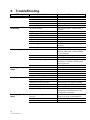
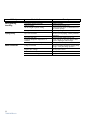
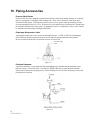
1
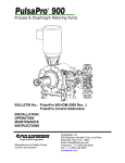
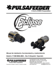
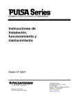
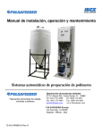
Installation Operation Maintenance Instruction MD Series Model#: Serial#: English Mechanical Diaphragm Metering Pump Pulsafeeder Factory Service Policy Should you experience a problem with your Pulsafeeder pump, first consult the troubleshooting guide in your operation and maintenance manual. If the problem is not covered or cannot be solved, please contact your local Pulsafeeder Sales Representative or Distributor, or our Technical Services Department for further assistance. Trained technicians are available to diagnose your problem and arrange a solution. Solutions may include purchase of replacement parts or returning the unit to the factory for inspection and repair. All returns require a Return Authorization number to be issued by Pulsafeeder. Parts purchased to correct a warranty issue may be credited after an examination of original parts by Pulsafeeder. Warranty parts returned as defective which test good will be sent back freight collect. No credit will be issued on any replacement electronic parts. Any modifications or out-of-warranty repairs will be subject to bench fees and costs associated with replacement parts. Safety Considerations: 1. Read and understand all related instructions and documentation before attempting to install or maintain this equipment 2. Observe all special instructions, notes, and cautions. 3. Act with care and exercise good common sense and judgment during all installation, adjustment, and maintenance procedures. 4. Ensure that all safety and work procedures and standards that are applicable to your company and facility are followed during the installation, maintenance, and operation of this equipment. Revision History: Rev A (1-28-15) - Created Document Copyright ©2015 Pulsafeeder, Inc. All rights reserved. Information in this document is subject to change without notice. No part of this publication may be reproduced, stored in a retrieval system or transmitted in any form or any means electronic or mechanical, including photocopying and recording for any purpose other than the purchaser’s personal use without the written permission of Pulsafeeder, Inc. ii Table of Contents 1. INTRODUCTION ..................................................................................................................................... 4 2. PRINCIPLES OF OPERATION .................................................................................................................. 4 2.1 Reagent Head Assembly ........................................................................................................ 5 2.2 Control Assembly .................................................................................................................... 5 2.3 Gear Ratio Assembly .............................................................................................................. 5 3. EQUIPMENT INSPECTION ....................................................................................................................... 6 3.1 Storage ..................................................................................................................................... 6 4. INSTALLATION ...................................................................................................................................... 6 4.1 Location .................................................................................................................................... 6 4.2 Piping System .......................................................................................................................... 7 4.3 Suction Pressure Requirements ............................................................................................ 8 4.4 Discharge Pressure Requirements ........................................................................................ 8 5. EQUIPMENT STARTUP ........................................................................................................................... 9 5.1 Check oil level .......................................................................................................................... 9 5.2 Fastener Inspection................................................................................................................. 9 5.3 Output Adjustment .................................................................................................................. 9 5.4 Priming the Reagent Head ...................................................................................................... 10 5.5 Calibration ................................................................................................................................ 11 6. M AINTENANCE ...................................................................................................................................... 12 6.1 Lubrication ............................................................................................................................... 12 6.2 Wet End Removal, Inspection, & Reinstallation ................................................................... 13 6.3 Check Valves ........................................................................................................................... 15 6.4 Motor Removal & Reinstallation ............................................................................................ 18 7. REPLACEMENT PARTS .......................................................................................................................... 19 7.1 KOPkit Program ....................................................................................................................... 19 7.2 Ordering KOPkits or Parts ...................................................................................................... 19 8. MODEL NUMBER IDENTIFICATION........................................................................................................... 20 9. TROUBLESHOOTING.............................................................................................................................. 21 10. PIPING ACCESSORIES ........................................................................................................................... 23 iii 1. Introduction The BLACKLINE® metering pump is positive displacement, mechanically operated reciprocating diaphragm pump. Each pump consists of a power end and a process end separated by a PTFE faced diaphragm. Individual pumps will vary in appearance due to various liquid ends and accessories; however, the basic principles of operation remain the same. 2. Principles Of Operation Figure 1, reagent head operation A diaphragm reciprocates at a preset stroke length, displacing an exact volume of process fluid. Diaphragm retraction causes the product to enter through the suction check valve. Diaphragm advance causes the discharge of an equal amount of the product through the discharge check valve. 4 72-001-02 Rev A 2.1 Reagent Head Assembly The typical reagent head assembly consists of reagent head, diaphragm, and suction and discharge cartridge check valves. This assembly is the only part of the pump to contact the process liquid; consequently, maintenance is critical to pump performance. 2.2 Control Assembly The BLACKLINE® pump incorporates a lost motion style of stroke length adjustment to limit diaphragm travel during the suction portion of each stroke. The stroke length setting is indicated by a (0% – 100%) scale located on the stroke adjustment assembly. Stroke length is changed by turning the hand knob. This turns a mechanism, which limits rearward travel of the diaphragm. Refer to Section 6.4 for further information. For automatic flow rate control, users can consider the Pulsafeeder VFD speed based control system, please contact your local Pulsafeeder dealer or representative for more information. 2.3 Gear Ratio Assembly BLACKLINE® pumps are driven by an electric motor mounted on the motor adaptor input flange. The motor drives a set of worm gears that convert rotational speed into torque. They, in turn, power the eccentric shaft assembly that converts rotary motion into reciprocating motion. Figure 2 5 72-001-02 Rev A 3. Equipment Inspection Check all equipment for completeness against the order and for any evidence of shipping damage. Shortages or damage must be reported immediately to the carrier and your authorized representative or distributor of BLACKLINE® pumps. 3.1 3.1.1 Storage Short Term Storage of your BLACKLINE® pump for up to 12 months is considered short-term. The recommended short-term storage procedures are: a) Store the pump indoors at room temperature in a dry environment. b) If required by the operating environment, take precautions to prevent entry of water or humid air into the eccentric enclosure. c) Prior to startup, perform a complete inspection and then start up in accordance with instructions in this manual. 3.1.2 Long Term Every twelve months, in addition to the above short-term procedures, verify the oil level, power up the motor and operate the pump for a minimum of one hour. It is not necessary to have liquid in the reagent head during this operation, but the suction and discharge ports must be open to atmosphere. After twelve months of storage, Pulsafeeder’s warranty cannot cover items that are subject to deterioration with age, such as seals, gaskets, and diaphragms. If the pump has been in storage longer than 12 months it is recommended that these items be inspected and replaced as necessary prior to startup. Materials and labor to replace this class of item under this circumstance are the purchaser’s responsibility. Consult your local Pulsafeeder representative for assistance in obtaining parts and service for your pump. 4. Installation 4.1 Location When selecting an installation site or designing a chemical feed system, consideration should be given to access for routine maintenance. BLACKLINE® pumps are designed to operate indoors and outdoors, but it is desirable to provide a hood or covering for outdoor service. External heating is required if ambient temperatures below 0 C (32 F) are anticipated, especially if pumps are not in continuous duty. Check with the factory if concerned with the suitability of the operating environment. The pump must be rigidly bolted to a solid and flat foundation to minimize vibration, which can loosen connections. When the pump is bolted down, care must be taken to avoid distorting the base and affecting alignments. The pump must be level within 5. This will assure that the check valves can operate properly. 6 72-001-02 Rev A 4.2 Piping System 1. All systems should include a pressure relief valve on the discharge side, to protect piping and process equipment, including the pump, from excess process pressures. An external relief valve is required! There should be no devices capable of restricting flow (such as a valve) located between the pump and the relief device. 2. Shutoff valves and unions (or flanges) on suction and discharge piping are recommended. This permits check valve inspection without draining long runs of piping, making periodic maintenance and inspection easier. Shutoff valves should be of the same size as connecting pipe. Ball valves are preferred since they offer minimum flow restriction. 3. Suction systems should include an inlet strainer, if appropriate for the product being pumped. Pump check valves are susceptible to dirt and other solid contaminants, and any accumulation can cause malfunction. The strainer should be located between the suction shutoff valve and the pump suction valve. It must be sized to accommodate the flow rate and the anticipated level of contamination. A 100 mesh screen size is generally recommended for up to 4 GPH, 60 Mesh for up to 13 GPH, 50 mesh for up to 26 GPH, 40 Mesh for up to 79 GPH and 30 mesh for flow rates above 80 GPH. 4. Vacuum/pressure gauges in the suction and discharge lines are helpful in order to check system operation. Gauges should be fitted with protective shutoff valves for isolation while not in use. 5. Piping weight must not be supported by valve housings or other portions of the reagent head, as the resulting stresses can cause leaks. If appropriate, provide for thermal expansion and contraction so that no excess force or moments are applied to the pump. 6. When making process connections, ensure that the check valve assemblies do not rotate as the threaded connections are secured. It is critical, especially with plastic construction, that the check valves not be too tight into the reagent head. The threaded connection between the check valve assembly and the regent head uses an o-ring seal and does not require sealing tape or any other sealant. 7. In piping assembly, use a sealing compound chemically compatible with the process material. Users of sealing tape are cautioned to ensure that the entering pipe thread ends are not taped, and that tape is removed from previously-used threads to the maximum practical extent prior to re-use. Both new and existing piping should be cleaned, preferably by flushing with a clean liquid (compatible with process material) and blown out with air, prior to connection to the pump. Debris from the piping system that prevents proper check valve operation is a common startup issue. 8. Note that for pumps which utilize cartridge-type check valve assemblies, no thread tape or sealant is required on the threads which secure the cartridge assembly to the pump reagent head. This area is sealed with o-rings integral to the cartridge. Sealant on these threads can actually degrade sealing capability. 9. For processes that require continuous non pulsating flow a pulsation dampener must be installed in the discharge line. 7 72-001-02 Rev A Suction Pressure Requirements Although BLACKLINE® metering pumps have some suction lift capability, a flooded suction (i.e., suction pressure higher than atmospheric pressure) is preferable whenever possible. The pump should be located as close as possible to the suction side reservoir or fluid supply source. For fluid with a vapor pressure of 5 psia or less (at operating temperature) the wet suction lift capability is approximately ten (5) feet. If this requirement is not met, the pump will not provide reliable, accurate flow. In suction lift conditions, the use of a foot valve is recommended at the lowest point of the pickup tube or pipe. Pumps under suction lift conditions may require some liquid priming before they will operate reliably. 4.3 Discharge Pressure Requirements All BLACKLINE® metering pumps are designed for continuous service at the rated discharge pressure. If system suction pressure exceeds discharge pressure (a condition sometimes described as “pumping downhill”), flow would be generated (siphoning) in addition to that caused by the pump. This results in a reduction in accuracy and loss of control over the metering process. To prevent this flow-through condition, the discharge pressure must exceed suction pressure by at least 0.35 Bar (5 psi). This can be achieved where necessary by the installation of a backpressure valve in the discharge line. Conditions where the actual discharge pressure exceeds the pump’s rating are to be avoided as they will cause damage to the pump components. Figure 3, sample system configuration 8 72-001-02 Rev A 5. Equipment Startup 5.1 Check oil level All pumps are supplied filled with oil. The prevent oil spills during shipping, a temporary plug is provided. Before starting up the pump replace the temporary plug with the operational plug. Check the oil level daily. 5.2 Fastener Inspection All pump fasteners should be checked prior to pump operation, and occasionally during use. This would include reagent head mounting bolts, motor mounting bolts, and the hardware that secures the pump to its foundation. Most hardware can be checked simply to ensure it is not loose. However, when checking reagent head bolt torque each bolt should be 44 lbf/inch. 5.3 Output Adjustment All BLACKLINE® pumps have a hand wheel for manual stroke adjustment. The hand wheel can be adjusted to any point from 0 to 100%. This value represents the stroke length setting and therefore the flow rate of the pump relative to its maximum output. 5.3.1 Stroke Length Adjustment The graduated knob from 0 to 10 rotates along a fixed linear vernier. The line of the fixed vernier is the benchmark to set the adjustment system at desired flow rate percentage value. One graduated knob complete turn corresponds to an adjustment change from 1% to 100%. Figure 4 9 72-001-02 Rev A 5.4 Priming the Reagent Head 1. When handling process liquids, follow all applicable personal and facility safety guidelines. 2. Ensure that the pump is ready for operation and that all process connections are secure. 3. Open the suction and discharge line shutoff valves. 4. If the piping system design and the storage tank are such that the product flows due to gravity through the pump, reduce the discharge pressure and the system will self prime when the pump is started. In the event the discharge line contains a significant amount of pressurized air or other gas, it may be necessary to lower the discharge pressure to enable the pump to self-prime. 5. If the installation involves a suction lift, it may be necessary to prime the reagent head and suction line. Operate the pump as in step 4 above; many times the pump will be capable of self priming. If it does not begin to pump, remove the discharge valve assembly. Carefully fill the reagent head through the discharge valve port with process (or compatible) liquid, and then reinstall the check valve. 6. Start the pump at the zero stroke length setting and slowly increase the setting to 100 to prime the pump. If this does not work, it will be necessary to fill the suction line. 7. Filling of the suction line will necessitate the use of a foot valve or similar device at the end of the suction line so that liquid can be maintained above the reservoir level. Remove the suction valve assembly, fill the line, replace the suction valve, then remove the discharge valve assembly and fill the reagent head as described in Step (5) above. The pump will now self-prime when started up per step (6) above. Use appropriate precautions if handling process fluid. Ensure that any other fluid used for priming is compatible with the product that will be pumped. Figure 5, process flow 10 72-001-02 Rev A 5.5 Calibration Figure 6, sample flow calibration curve All metering pumps must be calibrated to accurately specify stroke length settings for required flow rates. A typical calibration chart is shown above. Although output is linear with respect to stroke length setting, an increase in discharge pressure decreases output uniformly, describing a series of parallel lines, one for each pressure (only two are shown). The theoretical output flow rate at atmospheric discharge pressure is based on the displacement of the diaphragm, stroke length and the stroking rate of the pump. With increasing discharge pressure there is a corresponding decrease in output flow. Pumps are rated for a certain flow at a rated pressure (check nameplate). Whenever possible, calibration should be performed under actual process conditions (i.e., the same or a similar process liquid at system operating pressure). To construct a calibration chart, measure the flow rate several times at three or more stroke settings (e.g., 25, 50, 75, and 100), plot these values on linear graph paper, and draw a best-fit line through the points. For stable conditions, this line should predict settings to attain required outputs. All users are encouraged to test the flow rate of their pump once installed in their system, to ensure best accuracy and reliable operation. 11 72-001-02 Rev A 6. Maintenance BEFORE PERFORMING ANY MAINTENANCE REQUIRING REAGENT HEAD OR VALVE (WET END) DISASSEMBLY, DISCONNECT POWER, BE SURE TO RELIEVE PRESSURE FROM THE PIPING SYSTEM AND, WHERE HAZARDOUS PROCESS MATERIALS ARE INVOLVED, RENDER THE PUMP SAFE TO PERSONNEL AND THE ENVIRONMENT BY CLEANING AND CHEMICALLY NEUTRALIZING AS APPROPRIATE. WEAR PROTECTIVE CLOTHING AND EQUIPMENT AS APPROPRIATE. Accurate records from the early stages of pump operation will indicate the type and levels of required maintenance. A preventative maintenance program based on such records will minimize operational problems. It is not possible to forecast the lives of wetted parts such as diaphragms and check valves. Since corrosion rates and operational conditions affect functional material life, each metering pump must be considered according to its particular service conditions. The BLACKLINE® KOPkit will contain all replacement parts normally used in a preventative maintenance program. It is recommended that spare parts and replacement oil be kept available at all times. 6.1 Lubrication BLACKLINE® pumps are supplied completely lubricated from the factory. For optimum pump performance under normal conditions, oil should be changed after the first 1000 hours of operation and 10,000 hours thereafter. For severe service in extreme temperatures or very dirty environments, this interval may be shorter. Check the oil level daily to ensure it is half way on the site indicator. NOTE: Chemically contaminated lubricants can cause wear, corrosion and leaking seals. Preferably, always replace all the oil rather than refilling to the site glass half way point. The oil filling plug, the oil level plug, and the oil drain plug, are all placed on the reduction gear body. The following images allow easy identification of the different plugs. The oil filling plug The oil level plug Following table shown quantity and type of lubricant oils suggested: 12 72-001-02 Rev A The oil drain plug Use lubricating oil different than suggested is permitted only if the characteristics are compatible/equivalent. Use mineral oil for gears with a ISO VG 320 viscosity index (320 cSt at 40 °C or 23 °E at 50 °C) The MD series holds 400mL of oil (approximately ½ quart) Suggested oils. OIL MAKE OIL TYPE/NAME SHELL OMALA OIL 320 ESSO SPARTAN EP 320 MOBIL MOBILGEAR 632 IP MELLANA OIL 320 AGIP BLASIA 320 6.2 Wet End Removal, Inspection, & Reinstallation IF THE DIAPHRAGM HAS FAILED, PROCESS FLUID MAY HAVE CONTAMINATED THE PUMP ECCENTRIC HOUSING (ALTHOUGH NORMALLY, ANY PROCESS FLUID BEHIND A FAILED DIAPHRAGM WOULD PASS THROUGH THE BOTTOM DRAIN HOLE). HANDLE WITH APPROPRIATE CARE. 6.2.1 Diaphragm Removal & Reinstallation Rupture of the diaphragm is usually caused by excessive pressure and/or handled fluid under high temperatures. The mechanical diaphragm lifespan is related to the actual working conditions of the pump: - over 20.000 hours, for intermittent service (12/24 hours) - 10.000 operating hours, with continuous service (24/24 hours) The values are estimates and may differ depending on actual pump service conditions. The disassembly and replacement of pump head and diaphragm instructions are the same for all pump models NOTE: BEFORE starting to disassemble, make sure there is no pressure or high temperature in the pipeline ! 13 72-001-02 Rev A Release the pump from suction and discharge pipeline, and clean adequately Disassemble both valve units from the pumphead Unscrew all pumphead locking screws (item# .29) then remove the head body (item#21) Unscrew the mechanical diaphragm (item#32) by turning it in anti-clockwise direction Clean inside the diaphragm chamber (item#33) and the head body (item#21), especially along the diaphragm pinching zone Before screwing on the new diaphragm, apply grease on diaphragm locking screw (threaded end of the slide item#102) Screw on the diaphragm (item#32) make sure it reaches the edge on the slide (item#102) Reassemble the pump head (item#21) following in reverse these instructions and refers to the figures about the type of pump Fix the pump head by means of the locking screws (item#29); see section 6.2 "fastener inspection" Figure 7 14 72-001-02 Rev A 6.3 Check Valves Most fluid metering service requirements are related to check valves. Service requirements usually stem from solids accumulation between valve and seat, corrosion of seating surfaces, erosion, or physical damage due to wear or the presence of foreign objects. The valve incorporates a ball, guide, and seat. Flow in the unchecked direction lifts the ball off the seat, allowing liquid to pass through the guide. Reverse flow forces the ball down, sealing it against the sharp edge of the seat. The guide permits the ball to rotate but restricts vertical and lateral movement in order to minimize “slip” or reverse flow. Ball rotation prolongs life by distributing wear over the entire surface of the ball. Since ball return is by gravity, the valve must be in the vertical position in order to function properly. Parts are sealed by “O”-rings. All BLACKLINE models utilize a convenient cartridge-type check valve. All check components are preassembled and the cartridge should be replaced as a unit. When replacing, note that valves are marked with the flow direction, as the suction and discharge configurations are different. Figure 9, check valves Figure 8, check valves to 60 GPH 15 72-001-02 Rev A Figure 10, check valves, DC3 and DC 4 Figure 9, check valves to 137 GPH 16 72-001-02 Rev A 6.3.1 Figure 10, check valves to 158 GPH to 396 GPH 17 72-001-02 Rev A 6.3.2 Check Valve Removal & Reinstallation, Cartridge type Valving that is of the cartridge design is intended to be replaced as an assembly. 1. Disconnect the power source to the drive motor. 2. Relieve all pressure from the piping system. 3. Take all precautions necessary to prevent contamination to the environment and personnel exposure to hazardous materials. 4. Close the inlet and outlet shutoff valves. 5. Disconnect the suction piping at the installed union near the suction port. 6. Loosen and remove the suction valve cartridge slowly to drain any liquid from the reagent head. 7. Disconnect the discharge piping at the installed union near the discharge port. 8. Loosen and remove the discharge valve cartridge slowly to drain any trapped liquid. 9. Reinstall both new valve assemblies, taking care to ensure that they are in the correct ports. Do not coat the threads of the cartridge valve with a pipe sealant. Each valve cartridge should be tightened only until the o-ring seal makes good contact with the reagent head surface. Overtightening will cause damage and result in leaks 10. Reinstall both suction and discharge piping. Secure the cartridge while making your external connections to prevent rotating the cartridge and over-tightening it into the pump. 6.4 Motor Removal & Reinstallation 1. Disconnect the power source to the drive motor. 2. Disconnect the motor wiring from the motor. 3. Remove the four bolts retaining the motor to the motor adaptor. The motor shaft fits into a bore on the pump input shaft. 4. Slide the motor shaft out of the pump input shaft. Be careful not to lift the pump input shaft up out of the pump. 5. Apply a lubricant such as Loctite™ Silver Grade® Anti-seize paste (or similar) to the motor shaft and key before reassembling.. 6. Reinstall the motor by sliding the motor shaft into the pump input shaft. 7. Insert and tighten the four bolts removed in step 3. 8. Reconnect the motor wiring to the motor. 9. Connect power to the drive motor. Figure 11, motor mounting Motor rotation must be wired for CW rotation, as viewed from the top of the motor, as noted by the arrow on the top of the pump housing. 18 72-001-02 Rev A 7. Replacement Parts 7.1 KOPkit Program BLACKLINE® KOPkits contain all replacement parts normally used in a preventative maintenance program. (Replacement oil is also available separately for preventative maintenance programs. Refer to Section 6 – Equipment Startup). There is a specific KOPkit for every BLACKLINE® pump model. Each KOPkit is packaged for extended storage. All BLACKLINE® pumps have the KOPkit number identified on the pump nameplate and Pulsafeeder order documents. KOPkits can also be selected from the technical data sheet shipped with the pump or by a Pulsafeeder representative. The kit is identified by the model number of the pump, the wetted end material, and the process connection thread type. Figure 12, KOPkit parts 7.2 Ordering KOPkits or Parts When ordering replacement parts always specify: Pump model and serial number (from pump nameplate), e.g., Model No. (MD2FAASN2C-XXX) with Serial No. F406365-3. 19 72-001-02 Rev A 8. Model Number Identification Position Sample 1 and 2 MD 3 and 4 3B Specifies Options MD = BLACKLINE model pump Size/Flow 1/ 2 / 3 / 4 – diaphragm diameter A / B / C / D – stroking rate See sales literature for flow/pressure ratings KTP – PVDF Head / PTFE Valve Seat / 5 to 7 KTP 8 N 9 1 9 VFD Options Liquid End Pyrex Valve Check BallSize PPP – Glass Filled Polypropylene Head / PVC Valve Seat / Pyrex Valve Check Ball AAS– 316SS Head / 316SS Valve Seat / 316SS Valve Check Ball280 KMM – PVDF Head / Incoloy 825 Valve Seat / Hastelloy C-276 Valve Check Ball Wetted materials N –NPT Connections B – BSPT connection 1 – TEFC - NEMA 56C, 1P, 115/230V, Motor Options 60Hz, 1/2 Hp 2 - TEFC - NEMA 56C, 3P, 230/460V, 50/60Hz, 1/2 Hp (VFD 10:1) 3- Ex.Proof - NEMA 56C, 1P, 115/230V, 60Hz, 1/2 Hp 4 - Ep. Proof - NEMA 56C, 3P, 230/460V, 60Hz, 1/2 Hp 5 - TEFC - IEC 71, 1P, 115/230V, 50/60Hz, .37kW 6 - TEFC - IEC 71, 3P, 220/380/460V, 50/60Hz, .37kW (VFD 10:1) 7 - Ex. Proof - IEC 71, 1P, 115/230V, 50/60Hz, .37kW 8 - Ex. Proof - IEC 71, 3P, 220/380/460V, 50/60Hz, .37kW X - No Motor - NEMA 56C Frame Ready Y - No Motor - IEC 71 Frame ReadyVFD A – No VFD installed C - VFD, 115/230V, NEMA 4X, IP65 Enclosure, 1 Phase, Motor 2 & 6 Only 10 20 72-001-02 Rev A Options XXX – No Options 9. TroubleShooting Difficulty Pump does not start No delivery Probable Cause Faulty power source. Blown fuse, circuit breaker. Broken wire. Wired improperly. Process piping blockage. Motor not running. Supply tank empty. Lines clogged. Closed line valves. Ball check valves held open with solids. Vapor lock, cavitation. Prime lost. Strainer clogged. Low delivery Stroke adjustment set at zero. Motor speed too low Check valves worn or dirty Calibration system error Product viscosity too high Delivery gradually drops. Delivery erratic. Delivery higher than rated. 21 72-001-02 Rev A Product cavitating Check valve leakage. Leak in suction line. Strainer fouled. Product change. Supply tank vent plugged. Leak in suction line. Product cavitating. Entrained air or gas in product. Motor speed erratic. Fouled check valves. Inadequate backpressure Suction pressure higher than discharge pressure. Back pressure valve set too low. Back pressure valve leaks. Remedy Check power source. Replace - eliminate overload. Locate and repair. Check diagram. Open valves, clear other obstructions. Check power source. Check wiring diagram. Fill tank. Clean and flush. Open valves. Clean – inspect, flush with clear fluid. Increase suction pressure. Re-prime, check for leak. Remove and clean. Replace screen if necessary. Increase stroke length setting. Check voltages, frequency, wiring, and terminal connections. Check nameplate vs. Specifications. Clean, replace if damaged Evaluate and correct Lower viscosity by increasing product temperature or dilution. Increase pump and/or piping size Increase suction pressure. Clean, replace if damaged. Locate and correct. Clean or replace screen. Check viscosity and other variables. Unplug vent. Locate and correct. Increase suction pressure. Consult factory for suggested venting. Check voltage and frequency. Clean, replace if necessary. Increase discharge pressure to obtain a minimum pressure difference of 5 pis from suction to discharge Install backpressure valve or consult factory for piping recommendations. Increase setting. Repair, clean, or replace. Difficulty Noisy gearing, knocking Probable Cause Discharge pressure too high. Water hammer. Stroke length at partial setting. Piping noisy. Low grease level. Pipe size too small. Motor overheats. Pipe runs too long. Pulsation dampener inoperative or flooded. No surge chamber or dampener used. Pump overloaded. High or low voltage. Loose wire. Incorrect motor wiring 22 72-001-02 Rev A Remedy Reduce pressure. Install pulsation dampener. Some operating noise is characteristic of lost motion pumps. Add or replace grease. Increase size of piping - install pulsation dampener. Install pulsation dampener in line. Refill with air or inert gas. Inspect and replace diaphragm and recharge. Install pulsation dampeners. Check operating conditions against pump design. Verify discharge pressure Check power source. Trace and correct. Verify and correct 10. Piping Accessories Pressure Relief Valves Pressure relief valves are designed to protect chemical feed systems from damage that may be caused by defective equipment or a blockage in the discharge line. These valves function to limit the pressure downstream of the pump. Field adjust the pressure relief valve to operate when the discharge pressure exceeds operating pressure by 10-15%. Pressure relief valve should always be adjusted to a setting below the maximum rated pressure of the pump. No potentially restrictive components, such as a valve, should be installed between the pump discharge and the PRV. Diaphragm Backpressure Valve A diaphragm backpressure valve creates constant back pressure. A PTFE or PTFE-faced diaphragm offers maximum chemical protection and service life, and seals spring and bonnet from product. Be sure to install with fluid flow in direction of arrow on valve body. Figure 13 Pulsation Dampener A pulsation dampener is a pneumatically charged diaphragm-type chamber that intermittently stores hydraulic energy. Used on the inlet, it can improve NPSHA (Net Positive Suction Head available) characteristics of the suction piping system. On the discharge line it will reduce discharge pressure and pulsating flow variations. Figure 14 23 72-001-02 Rev A USA European Union (EU) Pulsafeeder, Inc. 27101 Airport Road Punta Gorda, FL 33982 USA (941) 575-3800 www.pulsatron.com Pulsafedeeder-Europe Via Kennedy, 12-20090 Segrate—Milano– Italy 24 72-001-02 Rev A