1
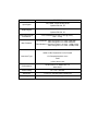
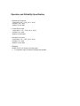
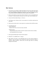
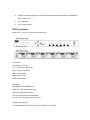
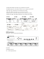
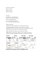
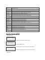
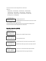
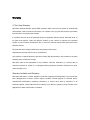
RF6T / RF6R Series Rack Mountable Fiber Optic/CAT5 DVI/HDMI Modular Extension Center Owner’s Manual Dtrovision LLC 9A Bergen Turnpike Little Ferry, NJ 07643 USA Tel: +1.201.488.3232 Fax: +1.201.621.6118 Email: [email protected] www.dtrovision.com For order support, please contact your local dealer. For technical support, please contact us at [email protected] RF6T/R Package Contents Please make sure all of the following items are included in the package; 1) RF6T/RF6R Frame 2) Transmitter/Receiver modules (if purchased separately) 3) DC 12V Power Supply Unit with a power cord 4) Rack ears 5) User Manual General Specification • RF6T/RF6R is a revolutionary 19’’ 1-RU size rack mount assembly for DVI/HDMI fiber optic/CAT5 extension modules. Various transmitter and receiver modules are designed for slot-loading into the RF6T/RF6R main frame. • Able to mix DVI/HDMI and Fiber Optic/CAT5 extension, RF6T/RF6R features one power supply for up to six modules per frame, eliminating a lot of small adapter type power supplies, housed in a 1 RU rack housing. • Compact & durable design and lower power consumption makes it an ideal solution for connection for high definition video/audio signal of digital displays such as LCD/Plasma/LED displays and projectors. • This pure fiber optic/CAT5 connection enables electrical noise free and EMI free that is ideal for long distance/mid-range extension of high definition DVI/HDMI signals with audio. • Intuitive LCD panel on both RF6T/RF6R show the status of the video and audio signals including the current signal image format and audio format. This information provides helpful diagnostic information. Model Input Signal Output Signal Supporting Display Resolutions RF6T/RF6R DVI, HDMI, 3.5mm Analog Audio Optional RS-232, IR DVI, HDMI, 3.5mm Analog Audio Optional RS-232, IR VGA ~WUXGA(up to 1920 x 1200 @ 60Hz) , 480i ~ 1080p CAT5 Modules: 1920x1200 @ 60Hz or at 1080p: 50M(165ft) Max. Distance 1280x1024 @ 60Hz or at 1080i: 60M(200ft) Fiber Modules: 1920x1200 @ 60Hz or at 1080p: 1,000M(3,300ft) 1280x1024 @ 60Hz or at 1080i: 1,530M(5,000ft) DC Power Jack HDMI 19 Pin Female/DVI 20 Pin Female Connector Type LC Receptacles with 4 cores RJ45 3.5mm Stereo Jack Conformations HDMI version 1.3/ DDWG DVI 1.0 With HDCP Power Rating DC +12V , 8W Max Dimension 17.3x6.7x1.7(inches) 440x170x44(mm) Weight 6.2 lbs (2.8 Kg) Operation and Reliability Specification 1. Operating Environment Temperature: 50F ~ 104F (10℃~ 40℃) Humidity: 10% ~ 80% Altitude: 3,000m Max. 2. Transit Environment Temperature: -13F ~ 140F (-25℃~ 60℃) Humidity: 5% ~ 95% Altitude: 15,000m Max. 3. Storage Environment Temperature: -4F ~ -49F (-20℃~ 45℃) Humidity: 5% ~ 95% Altitude: 3,000m Max. 4. Reliability MTBF: 90% at over 50,000 hours aging test In compliance with LCD Monitor reliability test standard Main Features 1. Zero loss & Zero noise delivery of digital high definition video and audio signal using optical conversion technology, RF6T/R delivers HD signals over fiber optic/Cat5 cables without loss or digital interference maintaining the clarity and colors. Noise cancellation and error correction logic enhances DVI/HDMI video and audio signals over long distance. 2. Built-in signal repeater to support longer distance between the source and the RF6T/R and the display. This Signal Repeater logic supports up to 50ft copper based DVI/HDMI cables. 3. Compact and Robust Module Design. 19’’ 1RU size 4. Long Distance (Up to 5000ft at 1080i or lower signal) over cost effective multimode fiber optic cables. 5. Mid-range (Up to 200ft at 1080i or lower signal) over cost effective RJ45 (CAT5/e/6) cables. 6. Full EDID Management 1) Built-in EDID library Choose one from 14 pre-saved most widely used EDID 2) EDID Emulation Saving/Emulating display’s EDID in the RF6T transmitter module enhances reliability and compatibility with various displays. 7. HDCP (High-bandwidth Digital Content Protection) Support. 8. DDWG DVI 1.0 and HDMI version 1.3 Support. 9. Signal Status LCD panel on both RF6T/RF6R video and audio signal information is displayed on the LCD panels to help understand the signal even before the display is connected. Display Resolution, refresh rates and audio signal status are intuitively displayed on the modules. Installation and Connection Instructions 1. Turn off both the video source and the display before connecting any cables. 2. Connect DVI/HDMI cable between the source and RF6T/Stand-alone transmitter AND between the RF6R/Stand-alone receiver and the display. 3. Cable Connection: 1) Fiber Cable: Connect LC terminated fiber optic cables according to the picture below; 2) CAT5 Cable: RT6T/RF6R was designed to conform to TIA/EIA-568-B Standard. Please ensure that each PIN layout of RF6T/RF6R is corresponding with the picture below before connecting the cable. Please note that CAT5e or above level cable enables to deliver better video quality and longer distance. TIA/EIA-568B Signal Pin Wire color Digital RGB 1 Orange/ White TMDS Data2+ 2 Orange TMDS Data2- 3 Green/ White TMDS Data1+ 4 Blue TMDS Data0+ 5 Blue/ White TMDS Data0- 6 Green TMDS Data1- 7 Brown/ White TMDS Clock+ 8 Brown TMDS Clock- 4. Connect the power supply unit to both RF6T/Stand-alone transmitter AND the RF6R/Standalone receiver units. 5. Turn on Display 6. Turn on Video Source RF6T Specification Dimensions: 17.3x6.7x1.7(inches) 440x170x44(mm) Front Panel: LCD Display: 16*2 LCD ST 1 ~ 6 LED: Input Slot Check Power: Power on/off button ▲▼◀▶: Move button MENU: Menu button ENTER: Enter button Rear Panel: DVI/HDMI IN: DVI-D/HDMI Input Audio IN: 3.5mm Stereo Audio Input 1234: Fiber Optical Receptacles CAT-5 IN: RJ45 (CAT5/e/6) Receptacles DC +12V: 12V DC Power Supply Unit Input Available Input Modules - DT1000: Optical, DVI, 3.5 Stereo, up to 6 modules can fit in RF6T - HT1000: Optical, HDMI, 3.5mm Stereo, up to 6 modules can fit in RF6T - DT1000RV: Optical, DVI, 3.5mm Stereo, RS-232, IR, up to 3 modules can fit in RF6T - DT50: CAT5, DVI, 3.5mm Stereo, up to 6 modules can fit in RF6T - HT50: CAT5, HDMI, 3.5mm Stereo, up to 6 modules can fit in RF6T - DT50R: CAT5, DVI, 3.5mm Stereo, RS-232, IR, up to 6 modules can fit in RF6T - HT50R: CAT5, HDMI, 3.5mm Stereo, RS-232, IR, up to 6 modules can fit in RF6T RF6R Specification Dimensions: 17.3x6.7x1.7(inches) 440x170x44(mm) Front Panel: LCD Display: 16*2 LCD ST 1 ~ 6 LED: Input Slot Check Power: Power on/off button ▲▼◀▶: Move button MENU: Menu button ENTER: Enter button Rear Panel: DVI/HDMI Output: DVI-D/HDMI Output Audio OUT: 3.5mm Stereo Audio Output 1234: Fiber Optical Receptacles CAT-5 : RJ45 (CAT5/e/6) Receptacles DC +12V: 12V DC Power Supply Unit Input Available Input Modules - DR1000: Optical, DVI, 3.5mm Stereo, up to 6 modules can fit in RF6R - HR1000: Optical, HDMI, 3.5mm Stereo, up to 6 modules can fit in RF6R - DR1000RV: Optical, DVI, 3.5mm Stereo, RS-232, IR, up to 3 modules can fit in RF6R - DR50: CAT5, DVI, 3.5mm Stereo, up to 6 modules can fit in RF6R - HR50: CAT5, HDMI, 3.5mm Stereo, up to 6 modules can fit in RF6R - DR50R: CAT5, DVI, 3.5mm Stereo, RS-232, IR, up to 6 modules can fit in RF6R - HR50R: CAT5, HDMI, 3.5mm Stereo, RS-232, IR, up to 6 modules can fit in RF6R RF6T/RF6R and available modules’ Compatibility Chart Part # Compatible Part # RF6T Hold DT1000, HT1000, DT1000RV, DT50, HT50, DT50R, HT50R RF6R Hold DR1000, HR1000, DR1000RV, DR50, HR50, DR50R, HR50R DT1000 Compatible with DR1000, DRS1000, OBC II RX, OLC RX HT1000 Compatible with HR1000, HRS1000, HDX II RX DT1000RV Compatible with DR1000RV, DWR1000RV, DWRS1000RV DT50 Compatible with DR50, DRS50, DCE RX HT50 Compatible with HR50, HRS50, HCE RX DT50R Compatible with DR50R, DRS50R, DCE RX HT50R Compatible with HR50R, HRS50R, HCE RX DR1000 Compatible with DT1000, DTS1000, OBC II TX, OLC TX HR1000 Compatible with HT1000, HTS1000, HDX II TX DR1000RV Compatible with DT1000RV, DWT1000RV, DWTS1000RV DR50 Compatible with DT50, DTS50, DCE TX HR50 Compatible with HT50, HTS50, HCE TX DR50R Compatible with DT50R, DTS50R, DCE TX HR50R Compatible with HT50R, HTS50R, HCE TX Operating Instruction (RF6T) 1. Initialization menu [VIDEO EXTENDER] TX - RF6T (V1.00) --> Model name and Main Firmware Version System Checking! SLOT1 Check OK --> Input Slot Status Check --> SLOT4 Check N.C: No module is connected to SLOT4 SLOT4 Check N.C SLOT5 Check OK 2. Main menu --> SLOT5 Check OK: Input module is connected to SLOT5 --> When Slot is connected and input signal is detected SLOT:123456 [ 1920 x 1080P/60 ] --> Display Selected Slot’s input signal information --> When Slot is not connected SLOT:123456 [ Slot N .C ] --> Slot N.C : No module is connected to Slot --> When Slot is connected but no input signal is detected SLOT:123456 [ No Signal ] --> No Signal: Module is connected but no input signal is detected * User Left/Right (◀▶) button to move a cursor to the left and right Selected Slot’s video timing will be displayed 3. Sub menu Press Menu button to go to sub-menu list. →1. V i d e o Info --> 1. Display each slot’s input video signal information 2. SLOT Firm Ver --> 2. Display each slot’s firmware version 3. E D I D Info --> 3. Display each slot’s saved EDID information 4. Int EDID Save --> 4. Display EDID information from built-in EDID library 5. Ext EDID save --> 5. Display EDID information from selected slot’s display device * User Up/down (▲▼) button to move to the next sub-menu list * Press menu button to cancel and go back to the main menu 4. Sub Menu detail [ 1. Video Info ] --> Display selected Slot # [ SLOT1 Time Info ] 1920 x1080P/60 --> Display input signal information * User Left/Right (◀▶) button to select slot # * User Up/down (▲▼) button to display selected slot’s information * Press menu button to cancel and go back to the main menu [ 2. Slot Firmware Version ] --> Display selected Slot # [ SLOT2 Firmware ] Soft Ver. : 1.00 --> Display firmware version * User Left/Right (◀▶) button to select slot # * Press menu button to cancel and go back to the main menu [ 3. Slot EDID Info ] [ SLOT3 EDIDInfo ] 1600x1200 --> Display selected Slot # (TST) --> Display EDID information * User Left/Right (◀▶) button to select slot # * Press menu button to cancel and go back to the main menu [ 4. Int EDID Save ] [ SLOT4 Int EDID ] →Sel : Up/Dn , Ent! --> Display selected Slot # --> Choose EDID from a built-in EDID library list [ SLOT4 Int EDID ] → 800x600 60Hz --> Display selected Slot # --> Display EDID information that will be saved to the module * User Left/Right (◀▶) button to select slot # * User Up/down (▲▼) button to see a built-in EDID library list (14 Pre-saved EDID) * Press menu button to cancel and go back to the main menu * EDID List - 800x600 60Hz , 1024x768 60Hz , 1280x768 60Hz , 1280x1024 60Hz - 1360x768 60Hz , 1366x768 60Hz , 1400x1050 60Hz , 1600x900 60Hz - 1600x1200 60Hz , 1680x1050 60Hz , 1920x1200 60Hz , HD1080i 60Hz - HD1080p (2CH) , HD1080p(Multi) [ 5. Ext EDID Save ] [ SLOT5 Ext EDID ] EDID Set : Enter! --> Display selected slot # --> Display EDID information that will be saved to the module * User Left/Right (◀▶) button to select slot # * Press Enter button to save EDID information from the selected slot’s display device * Press menu button to cancel and go back to the main menu Operating Instruction (RF6R) 1. Initialization menu [VIDEO EXTENDER] RX - RF6R (V1.00) --> Model name and Main Firmware Version System Checking! SLOT1 Check OK --> Input Slot Status Check --> SLOT4 Check N.C: No module is connected to SLOT4 SLOT4 Check N.C SLOT5 Check OK --> SLOT5 Check OK: Input module is connected to SLOT5 2. Main menu --> When Slot is connected and input signal is detected SLOT:123456 [ 1920 x 1080P/60 ] --> Display selected Slot’s input signal information --> When Slot is not connected SLOT:123456 [ Slot N .C ] --> Slot N.C : No module is connected to Slot --> When Slot is connected but no input signal is detected SLOT:123456 [ No Signal ] --> No Signal: Module is connected but no input signal is detected * User Left/Right (◀▶) button to move a cursor to the left and right Selected Slot’s video timing will be displayed 3. Sub menu Press Menu button to go to sub-menu list →1. V i d e o I n f o --> 1. Display each slot’s input video signal information 2. SLOT Firm Ver --> 2. Display each slot’s firmware version 4. Sub Menu detail [ 1. Video Info ] --> Display selected Slot # [ SLOT1 Time Info ] 1920 x1080P/60 --> Display input signal information * User Left/Right (◀▶) button to select slot # * User Up/down (▲▼) button to display selected slot’s information * Press menu button to cancel and go back to the main menu [ 2. Slot Firmware Version ] --> Display selected Slot # [ SLOT2 Firmware ] Soft Ver. : 1.00 --> Display firmware version * User Left/Right (◀▶) button to select slot # * Press menu button to cancel and go back to the main menu Technical Specification Data Transfer Speed: Frequency Range: Supporting Display Resolutions: I/O Signal Standard: Max Distance: Up to 2.25 Gbps (DVI Single Link), 10 Gbps (HDMI) 25 ~ 165 Mhz 1080p / Up to WUXGA (1920X1200)@60Hz DVI 1.0, HDMI 1.3, TMDS CAT5 Modules: 1920x1200 @ 60Hz or at 1080p: 50M(165ft) 1280x1024 @ 60Hz or at 1080i: 60M(200ft) Fiber Modules: 1920x1200 @ 60Hz or at 1080p: 1,000M(3,300ft) Optical Source: Optical Cable Specification: Input Ports: Output Ports: Power Consumption: Power Rating: 1280x1024 @ 60Hz or at 1080i: 1,530M(5,000ft) 850 nm Vcsel Multimode 50/125 or, 62.5/125 DVI-D Female 29P / HDMI Female 19P / LC Receptacles x 4 cores / RJ45 / 3.5mm Stereo Jack DVI-D Female 29P / HDMI Female 19P / LC Receptacles x 4 cores / RJ45 / 3.5mm Stereo Jack 8 Watts (Max) 12V DC / 3A Warranty 2 (Two) Year Warranty Dtrovision warrants this fiber optical HDMI extension cable to be free from defects in workmanship and materials, under normal use and service, for a period of two (2) year from the date of purchase from Dtrovision or its authorized resellers. If a product does not work as warranted during the applicable warranty period, Dtrovision shall, at its option and expense, repair the defective product or part, deliver to customer an equivalent product or part to replace the defective item, or refund to customer the purchase price paid for the defective product. All products that are replaced will become the property of Dtrovision. Replacement products may be new or reconditioned. Any replaced or repaired product or part has a ninety (90) day warranty or the reminder of the initial warranty period, whichever is longer. Dtrovision shall not be responsible for any software, firmware, information, or memory data of customer contained in, stored on, or integrated with any products returned to Dtrovision for repair under warranty or not. Warranty Limitation and Exclusion Dtrovision shall have no further obligation under the foregoing limited warranty if the product has been damaged due to abuse, misuse, neglect, accident, unusual physical or electrical stress, unauthorized modifications, tampering, alterations, or service other than by Dtrovision or its authorized agents, causes other than from ordinary use or failure to properly use the Product in the application for which said Product is intended. FCC/CE Statement This device complies with part 15 of FCC Rules and EN 55022/55024/61000-3 for CE certification. Operation is subject to the following two conditions: (1) this device may not cause harmful interference, and (2) this device must not accept any interference received, including interference that may cause undesired operation. This equipment has been tested and found to comply with the limits for a Class A digital device, pursuant to part 15 and 2 of FCC Rules and EN 55022/55024/61000-3 for CE certification. These limits are designed to provide reasonable protection against harmful interference when the equipment is operated in a residential installation. This equipment generates, uses, and can radiate radio frequency energy and. if not installed and used in accordance with the instruction guide, may cause harmful interference to radio communications. However, there is no guarantee that interference will not occur in a particular installation. If this equipment does cause harmful interference to radio or television reception, which can be determined by turning the equipment off and on, the user is encouraged to try to correct the interference by one or more of the following measures: Re-orient or relocate the receiving antenna. Increase the separation between the equipment and the receiver. Connect the equipment into an outlet on a circuit different from that to which the receiver is connected. Consult a service representative for help. Properly shielded and grounded cables and connectors must be used in order to comply with FCC/CE emission limits. Changes or modifications not expressly approved by the party responsible for compliance could void the user s authority to operate the equipment. UL Statement This device has completed a UL Commercial Inspection and Testing Services for the multimode HDMI cable complied with VW-1 under UL 758. it is validated by the UL file number SV2038 and project number 04CA05353.