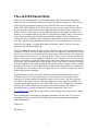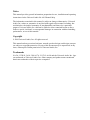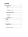
1
Model LA-610
Channel Strip
Universal Audio Manual Number 65-0901
Revision 1.1
Universal Audio, Inc.
www.uaudio.com
(866) 823-1176 Toll Free
(877) 698-2834 Toll Free Customer Service
(831) 466-3737 voice
(831) 466-3775 fax
The LA-610 Channel Strip
Thank you for purchasing the LA-610 Channel Strip. This unit combines a modified
channel of our 2-610 Mic Pre with an LA2A style T4 Optical Compressor. Our 610 was
inspired by the microphone preamp section of the 610 tube console designed by my
father, M.T. “Bill” Putnam, in the 1950s. The 610 was a rotary-control console and was
the first console of the modular design. Although technologically simple compared to
modern consoles, the 610 possessed a warmth and character that kept it in demand for
decades. As a prominent part of my father’s United/Western studios, the 610 was used on
many classic recordings by Frank Sinatra and Sarah Vaughan. The Beach Boys Pet
Sounds, the Doors LA Woman, and Van Halen’s debut album were all recorded on the
610. The legendary Wally Heider used the 610 in his remote truck for many of his bestknown live recordings. At Ocean Way Studios (formerly United), the 610 is lovingly
preserved and still used in Studio B.
The T4 Compressor element in the LA-610 is identical to the circuit components housed
inside the T4 optical cell used on the legendary LA-2A compressor. The heart and soul of
the LA-2A is mostly a result of this special optical gain control element. The unique and
musical behavior of the LA-2A is present in the LA-610 as well, the main difference
being a more colored sonic signature with the LA-610. Unlike the LA-2A, the LA-610
offers a wide variety of tone and character by virtue of the dual stage level controls and
EQ section. The incredible price/value of the LA-610 is the result of using the existing
610 tube amplifier and simply adding the T4 optical element creating a mono channel
strip that can serve as a mic or Instrument preamp with or without EQ and compression.
In addition, the LA-610 has a line level input for use as a dedicate compressor with or
without EQ and tube saturation.
In addition to the LA-610, Universal Audio has released reproductions of the classic
Teletronix LA-2A Leveling Amplifier and 1176LN Limiter as well as the 610 tube
preamp and 2108 microphone preamplifier, which is based on the 1108 line amps that
were used in my father’s studios. Universal Audio also creates software emulation’s of
our vintage hardware that run on our UAD-1 DSP card as well as Digidesign’s Pro Tools
platform. All of these products are designed to meet the demands of the modern
recording studio, yet retain the character of vintage equipment. Please visit
www.uaudio.com to see and read about other great recording tools from Universal Audio.
These products have been quite an enjoyable adventure to develop and we’re sure the
next phase will be even more fun! We thank you for your support and we thank my
father, Bill Putnam.
Thank you,
Bill Putnam
ii
IMPORTANT SAFETY INSTRUCTIONS
Before using this unit, be sure to carefully read the applicable items of these operating instructions and the
safety suggestions. Afterwards keep them handy for future reference. Take special care to follow the
warnings indicated on the unit, as well as in the operating instructions.
1.
2.
3.
4.
5.
6.
7.
8.
Water and Moisture – Do not use the unit near
any source of water or in excessively moist
environments.
Object and Liquid Entry – Care should be
taken so that objects do not fall, and liquids are
not spilled, into the enclosure through openings.
Ventilation – When installing the unit in a rack
or any other location, be sure there is adequate
ventilation. Improper ventilation will cause
overheating, and can damage the unit.
Heat – The unit should be situated away from
heat sources, or other equipment that produce
heat.
Power Sources – The unit should be connected
to a power supply only of the type described in
the operating instructions, or as marked on the
unit.
Power Cord Protection – AC power supply
cords should be routed so that they are not likely
to be walked on or pinched by items placed upon
or against them. Pay particular attention to cords
at plugs, convenience receptacles, and the point
where they exit from the unit. Never take hold of
the plug or cord if your hand is wet. Always
grasp the plug body when connecting or
disconnecting it.
Grounding of the Plug – This unit is equipped
with a 3-wire grounding type plug, a plug having
a third (grounding) pin. This plug will only fit
into a grounding-type power outlet. This is a
safety feature. If you are unable to insert the plug
into the outlet, contact your electrician to replace
your obsolete outlet. Do not defeat the purpose of
the grounding-type plug.
Carts and Stands – The unit should be used only
with a cart or stand that is recommended by the
manufacturer. The unit and cart combination
should be moved with care. Quick stops,
excessive force and uneven surfaces may cause
the unit and cart combination to overturn.
9. Wall Or Ceiling Mount – The unit should be
mounted to a wall or ceiling only as
recommended by the manufacturer.
10. Cleaning – The unit should be cleaned only as
recommended by the manufacturer.
11. Nonuse Periods – The AC power supply cord of
the unit should be unplugged from the AC outlet
when left unused for a long period of time.
12. Damage Requiring Service – The unit should be
serviced by a qualified service personnel when:
a) The AC power supply cord or the plug has
been damaged: or
b) Objects have fallen or liquid has been
spilled into the unit; or
c) The unit has been exposed to rain; or
d) The unit does not operate normally or
exhibits a marked change in performance; or
e) The unit has been dropped, or the enclosure
damaged.
13. Servicing – The user should not attempt to
service the unit beyond that described in the
operating instructions. All other servicing should
be referred to qualified service personnel.
iii
Notice
This manual provides general information, preparation for use, installation and operating
instructions for the Universal Audio LA-610 Channel Strip.
The information contained in this manual is subject to change without notice. Universal
Audio, Inc. makes no warranties of any kind with regard to this manual, including, but
not limited to, the implied warranties of merchantability and fitness for a particular
purpose. Universal Audio, Inc. shall not be liable for errors contained herein or direct,
indirect, special, incidental, or consequential damages in connection with the furnishing,
performance, or use of this material.
Copyright
© 2004 Universal Audio, Inc. All rights reserved.
This manual and any associated software, artwork, product designs, and design concepts
are subject to copyright protection. No part of this document may be reproduced, in any
form, without prior written permission of Universal Audio, Inc.
Trademarks
LA-2A, 1176LN, 2-610, 2108, 6176, 2-1176, LA-610 and the Universal Audio, Inc. logo
are trademarks of Universal Audio, Inc. Other company and product names mentioned
herein are trademarks of their respective companies.
iv
Table Of Contents
LA-610 Specifications....................................................................................1
LA-610 Operating Instructions.......................................................................2
610 Front Panel ................................................................................2
Input Select.............................................................................2
Gain ........................................................................................3
Level.......................................................................................3
Pad..........................................................................................4
Polarity ...................................................................................4
+48 V (Phantom Power)..........................................................4
EQ Controls ............................................................................4
T4 Optical Compressor Front Panel ...................................................5
Peak Reduction ..........................................................................5
Gain...........................................................................................5
Limit/Compress .........................................................................5
Meter Function ..........................................................................6
Meter Calibration.......................................................................6
Meter Function ..........................................................................6
Meter Calibration.......................................................................6
LA-610 Rear Chassis .....................................................................................6
Input/Output ........................................................................................6
AC Power ...........................................................................................7
Fuse/Mains ..........................................................................................7
Voltage Select .....................................................................................7
Compressor Theory of Operation ...................................................................8
Compressor Basics ..............................................................................8
Gain Reduction Circuits ......................................................................8
Historical Notes ...........................................................................................13
The 610 Preamp ................................................................................13
The 1176 and LA-2A Compressors....................................................15
The LA-2A........................................................................................16
v
LA-610 Specifications
Microphone Input Impedance
Selectable, 500 or 2k Balanced Line Input Impedance
20k Hi-Z Input Impedance
Selectable, 2.2M or 47k Maximum Microphone Input Level
-8 dBu (2K input Imp. & 15 dB Pad in)
Maximum Output Level
+20 dBu (120Vac line)
Internal Output Impedance
80 Recommended Minimum Load
600 Frequency Response
20 Hz to 20 kHz +/- 0.5dB
Maximum Gain
40 dB (Line), +77dB (Mic)
Noise Floor
-72 dBu 20 – 20kHz (Line In,
Tube Complement
(3)12AX7, (1)12AT7A, (1)6AQ5
General:
Power Requirements:
115V / 230V operation
Dimensions:
3.5” vertical, 19” rack (2RU).
Weight:
12 lbs. (Boxed,14.5 lbs.)
1
Unity Gain)
LA-610 Operating Instructions
The LA-610 is a vacuum-tube microphone/instrument/line preamplifier with basic EQ
and an optical program dependent compressor. The main preamp circuit has two gain
stages that utilize a dual-triode tube operating in a class A single-ended configuration.
Variable negative feedback is applied to both of these stages to control gain, distortion,
and frequency response. Balanced inputs and outputs are transformer coupled.
610 Front Panel (left side)
This panel has the Input Select, Gain, Level, EQ, Pad, Polarity and +48 volt Phantom
controls as well as a Hi-Z Input. Each control is discussed in the following sections.
GAIN -5 0 +5
-10
+10
-15 dB
HIGH
LEVEL
PAD
4
OUTø
7K
5
6
3
Mic
Line Hi-Z
2.0K
500
47K
IN ø
+48V
2.2M
10K
7
-1.5 0 +1.5
-3
+3
-4.5
4.5K
+4.5
-6
+6
-9
2
8
1
LOW
100
9
OFF
0
10
200
-1.5 0 +1.5
-3
+3
-4.5
70
Tube Mic Pre
+9
+4.5
-6
+6
-9
+9
Hi-Z
Figure 1: 610 Front Panel
Input Select
The Input Select switch determines which input is active: Mic, Line, or Hi-Z. Within both
the Mic and Hi-Z areas, the switch includes two settings to select different input
impedances.
•
Mic: Selects the signal from the rear-panel, balanced, MIC INPUT XLR connector.
The impedance for the MIC INPUT can be set to 500 or 2K . Switching between
these two positions while listening to a connected microphone may reveal a different
tonal quality and / or gain. A typical mic preamplifier should have an input
impedance equal to about 10 times the mic output impedance. For example, if your
mic has an output impedance between 150 and 200, set the switch to the 2K
position. However, since making music is not necessarily about adhering to technical
specifications, feel free to experiment with the settings to attain the desired sound.
You will not harm your microphone or the LA-610.
•
Line: Selects the signal from the rear-panel, balanced, LINE INPUT XLR connector.
LINE INPUT has an input impedance of approximately 13 k ohms and is intended to
accommodate mixers, tape machines, other mic preamps or any device with a line
2
level output, such as keyboards, sound modules and drum machines. The LA-610
may be used as a “tone box” in this configuration, offering a variety of sonic colors
based on the front panel control settings.
•
Hi-Z: Selects the signal from the front panel, unbalanced Hi-Z 1/4”connector. This
input can have an input impedance of 47K or 2.2M and is intended for bass,
guitar or any instrument with a magnetic or acoustic transducer pickup. The 47K setting is best suited for -10 dBv level signals, typically found on active basses and
guitars. The 2.2M setting is appropriate for instruments with passive pickup
systems. Since an instrument’s output impedance may be somewhere between the
active and passive levels, feel free to experiment to achieve the best sound at the
desired level.
Gain
The Gain control adjusts the gain of the input stage in 5 dB increments. Turning the
switch clockwise reduces the negative feedback, which raises the gain. In addition to
changing the volume, the Gain control also alters the amount of the tube’s harmonic
distortion, a major contribution to the warm sound characteristic of tube equipment.
Level
The Level knob is the master volume control. It determines the amount of signal from the
preamplifier gain stage sent to the compressor stage. The cleanest signal is attained by
setting the Level knob between 7 and 10 on the scale, then turning the Gain knob until the
desired level is attained. Altering the Gain, Impedance, and Output controls together
provides many useful tonal variations. The numeric values on the front panel for the
Level control denote magnitude and are NOT specific dB values. The Level control also
effects the threshold point where the compressor begins to affect the signal level. With
the level up high, the compressor PEAK control will need to be set lower for subtle
compression. With the LEVEL set low, the compressor PEAK control will need to be set
higher for agressive compression.
Pad
The front panel toggle switch labeled PAD will attenuate the Mic input level by 15dB
when the switch is “up”. When undesired distortion is present at low gain levels it is
recommended to engage the Pad switch then turn up the GAIN control as needed.
Polarity
The front panel toggle switch labeled IN and OUT determines the polarity of the
LINE OUTPUT. When IN is selected, pin 2 is hot (positive). When OUT is
selected, pin 3 is hot (positive).
+48 V (Phantom Power)
Most modern condenser mics require phantom voltage to operate and we recommend
checking the requirements of your microphones before connecting them. It is good
practice to keep phantom power off (switch down) when it is not required. To avoid loud
transients, always keep the phantom power off when connecting or disconnecting
microphones.
EQ Controls
The 610 has both low and high frequency shelving-type equalizers, each with two
controls:
3
•
Frequency: This toggle switch selects the corner frequency (Hz). High: 4.5K, 7K,
10K; Low: 70, 100, 200
•
Boost/Cut: This rotary switch selects the amount of boost or cut applied to the
frequency “shelf.” The positive and negative numbers on the front panel denote dB
values.
4
T4 Optical Compressor Front Panel (right side)
This panel has the Peak Reduction, Gain, Meter Function and Compressor Mode
controls. Each control is discussed in the following sections.
PEAK REDUCTION
4
5
5
4
6
3
6
3
7
2
PREAMPCOMPOUTPUT
GAIN
8
7
2
8
METER
BYP
1
9
0
10
1
COMP
LIMIT
9
0
10
T4 Optical Compressor
MODE
Figure 2: T4 Optical Compressor Front Panel
Peak Reduction
The compressor section Peak Reduction control determines when the compressor
receives a signal “loud” enough to trigger gain reduction as well as total output level.
Higher settings will increase the relative amount of compression. Heavily compressed
signals can be made louder by increasing the large Gain knob just to the right of the Peak
control knob.
Gain
The Gain control determines the final output level from the LA-610. Once the desired
amount of limiting is set by adjusting the Peak Reduction Control, the Gain Control can
be used to set the required output level. Set the Meter switch to the Output position so
that the meter reads the desired output level from the LA-610.
Limit/Compress
The Limit/Compress Switch changes the characteristics of the compressor I/O curve.
When in the Compress position, the curve is gentler, and presents a low compression
ratio. A higher compression ratio results when the switch is set to the Limit position.
Meter Function
The VU meter can be used to indicate 610 preamp output section (feeding the compressor
section), compressor gain reduction or final output level. The Meter function is
determined using the three position knob to the left of the meter. When Output is
selected, a meter reading of 0 corresponds to an output level of +4 dBm at the LA-610
output.
5
Meter Calibration
The 0dB gain reduction reading may need to be calibrated using the GR Zero Set pot.
The GR Zero Set pot is located through a small hole on the front panel below the UA
diamond logo.
1) Turn the LA-610 on and warm up for 5 minutes.
2) Set the meter knob to the GR position.
3) With the Compressor section (right side) Peal Reduction control full off (CCW) adjust
the GR Zero Set trim pot so the meter reads 0 dB. Turn pot slowly and watch how meter
settles.
LA-610 Rear Chassis
On the left, AC Power input with fuse holder.
On the right, the LA-610 MIC INPUT, LINE INPUT, and LINE OUTPUT XLR
connectors. These connectors are discussed in the following sections.
POWER IN:
115V ~ 50/60Hz 400ma
230V ~ 50/60Hz 200ma
FUSE RATING:
T 400ma L 115V~
T 200ma L 230V~
REPLACE FUSE WITH SAME
RATING AND TYPE ONLY!
!
CE
CAUTION / AVIS
RISK OF ELECTRIC SHOCK
DO NOT OPEN
RISQUE DE CHOC ELECTRIQUE
NE PAS OUVRIR
LINE
OUTPUT
CAUTION: TO REDUCE THE RISK OF FIRE OR
ELECTRICAL SHOCK DO NOT EXPOSE THIS
PRODUCT TO RAIN OR MOISTURE
ATTENTION: POUR REDUIRE LE RISQUE DU FEU
OU DE CHOC ELECTRIQUE N'EXPOSEZ PAS CE
PRODUIT A LA PLUIE OU A L'CHUMIDITE'
LINE
INPUT
MIC
INPUT
UNIVERSAL AUDIO, •INC
SANTA CRUZ, CALIF. USA
Figure 3: LA-610 Rear Chassis
Input/Output
Standard XLR input and output connectors are provided on the rear panel. Pin 2 is wired
positive (hot) on the LINE and MIC INPUTS. Pin 2 is positive on the LINE OUTPUT
when the front panel Polarity toggle switch is down (IN ). Pin 3 is positive on the LINE
OUTPUT when the front panel Polarity switch is up (OUT ).
AC Power
The LA-610 uses a standard, detachable IEC power cable.
Fuse/Mains
The AC power fuse is located in the AC power connector block. Remove the power cord
before checking or changing the fuse.
A 400 mA time delay (slow blow) fuse is required for operation at 115 V.
A 200 mA time delay (slow blow) fuse is required for operation at 230 V.
6
Voltage Select
The LA-610 can operate at 115 V or 230 V. To change the mode, wait 5 minutes after
power down, unplug the AC power cord from the rear chassis. Remove the top cover.
As shown below, the Voltage Select Cable can be plugged into one location for 115V
operation or moved to the 230V Connector for 230V operation. This figure shows the
unit configured for 115V operation. The connector is part of the wiring that comes from
the power transformer located at the rear of the LA-610 next to the main AC power inlet.
When changing operating voltage, the fuse value must be changed as well. Make sure
the LA-610 is properly set for the voltage in your area before applying AC power to unit!
Figure 4: 115V / 230V Voltage Select Jumper
Compressor Theory of Operation
Compressor Basics
Before we dig in to a description of the compressor circuit, it is useful to examine the
general characteristics of compressors and review some terminology. The chart below
(Figure 4) depicts the input/output characteristics of a compressor, an expander and a
perfect amplifier. When operated within its specified range, an amplifier provides a
constant amount of gain regardless of the level of the input signal. In figure 4 below, the
middle line depicts a perfect amplifier with a gain of 10 dB. To see this, notice that a
signal with an input level of –30 dB will result in an output level of –20 dB, which is an
increase of 10 dB. Similarly, an input level of 0 dB will result in an output level of 10
dB, hence the gain stays fixed at 10 dB regardless of the input level.
7
Expansion
Perfect
amplifier
+10
Compression
0
Output
Level (dB
B) -10
-20
-30
-30
-20
-10
0
+10
Input Level (dB
B)
Figure 4- Input/output characteristics of a compressor, an expander and a perfect
amplifier.
In contrast to an amplifier, whose job is to present a constant gain, a compressor varies its
gain in response to the level of the input signal. Large input signals result in less gain,
thus reducing or “compressing” the dynamic range of the signal. Referring again to the
line marked “compression” in Figure 4, we see that an input level of –30 dB results in an
output level of –20 dB, indicating a gain of 10 dB. Repeating this for input levels of –20
dB and –10 dB, we see that the compressor exhibits gains of 5 dB and 0 dB respectively.
From this, it is clear that the gain decreases as the input signal increases.
Referring to the diagram, we see that the compressor will increase its output level by 5
dB for every 10 dB that we increase the input level. The compression ratio is defined as
the ratio of these two numbers. In this case the compression ratio would be 10:5, which
can be reduced to 2:1.
As an aside, an expander is a device which increases the dynamic range of a signal. For
example, a 10dB change in the input signal might result in a 20 dB change in the output
signal, thus “expanding” the dynamic range.
There are several other terms related to compression that can be demonstrated by
referring to Figure 2. The amount of compression or gain reduction is typically given in
dB and is defined as the amount by which the signal level is reduced by the compressor.
Graphically, this can be understood by looking at the difference in levels between what
would have been the uncompressed (the output from an amplifier) output level and the
compressed output level. This value is what is displayed by the LA-610 meter when it is
switched to comp mode.
8
As mentioned previously, the compression ratio is defined as the ratio of the increase of
the level of the input signal to the increase in the level of the output signal. In this
example, the input level is increased by 10 dB while the output level only increases 5 dB.
This would be a compression ratio of 2:1. Lower ratios such as 2:1 result in more gentle
compression. (Note that a compression ratio of 1:1 is no compression at all).
Typically, compressors let you choose a threshold. This is the point at which gain
reduction starts to take place. When an audio signal is below this threshold the
compressor acts like an amplifier and there is no gain reduction. Above the threshold the
slope becomes less than 45 degrees, indicating gain reduction and hence compression.
The point at which a compressor transitions into compression is commonly called the
knee. In practical compressors, this transition is gentler than what is depicted in the
diagram.
Many modern compressors provide a control which adjusts the threshold directly. In the
case of the LA-610, the Peak Reduction knob controls both the threshold and the amount
of compression.
Compression regio
on
+10
10 dB of
compression
0
Output
Level (dB
B) -10
2:1 Compressiion
knee
-20
-30
-30
-20
-10
0
+10
Input Level (dB
B)
Figure 5: Input/output curve of a compressor with a ratio of 2:1 and a threshold of -20
dB.
Gain Reduction Circuits
A brief overview of the operation will be provided here. The input transformer provides
isolation and impedance matching. After this the signal is fed into both the side-chain
circuit and the gain reduction circuit. The side-chain is comprised of a voltage amplifier,
a pre-emphasis filter, and a driver stage which provides the voltage necessary to drive the
9
electro-luminescent panel. This signal controls the gain of the compressor. After the
gain reduction circuit, the signal is sent through an Output Gain control and a two-stage
output amplifier, followed by the output transformer.
As mentioned previously, compressors are devices that vary their gain in a manner which
is dependent upon the level of the input signal. In order to do this, the compressor must
first have some method of determining the level of the signal, and must then be able to
use this to control the gain. There are many different schemes to accomplish these tasks.
In the case of the LA-610, both of these functions are performed by the T4, which is an
electro-optical element.
Electro
-luminescen
nt
Panel
Photo
-Electric Celll
Figure 5 : Diagram of the T4 electro-optical cell.
The cell T4 is comprised of an electro-luminescent (EL) panel and a photo-electric cell
housed in a light proof box or can. The EL panel is essentially a night-light. As you
would expect, the larger the signal that is applied to it, the brighter the light that is
generated. This light shines upon the photo-electric cell. A photo-electric cell is a light
sensitive device whose resistance changes depending upon the intensity of light to which
it is subjected; the brighter the light, the less resistance the photo-cell will have.
The photo-cell is used to control the gain of the circuit. Essentially, the photo-cell acts as
the bottom leg in a voltage divider circuit. The lower the resistance of the photo-cell, the
lower the signal voltage will be at the output of the gain reduction stage. To see why this
is true, we can look at the extreme cases. If the resistance is extremely high (this is the
case when there is a small input signal and the light is off) then the photo-cell does not
affect the circuit and there is no gain reduction. The second case we can look at is when
there is a large signal present. In this condition, the light shines brightly and the photocell exhibits very low resistance. If the resistance of the photo-cell becomes zero (a dead
short), then the signal would be grounded and there would be no output. In reality, the
10
photo-cell resistance can not go completely to zero and hence there will always be some
signal present.
The T4 electro-optical device is the heart of the compressor and its gain reduction
characteristics. Its unique characteristics affect the overall sound and character of the
LA-610.
In addition to the compression curve, the combination of the EL panel and the photo-cell
determine the attack and release characteristics of the LA-610. This is one of the most
important contributors to the sound of the LA-610. Unlike other compressors which
allow the user to adjust these parameters, the attack and release of the LA-610 are
completely determined by the T4.
There are several important characteristics of the T4 which play crucial roles in the
sound of the LA-610. The first is the attack. The LA-2A was the first electro-optical
compressor to use an electro-luminescent panel for the light source. Previous attempts at
electro-optical compression employed either neon or incandescent lights. Both of these
took time to light up, and this delay resulted in slow attacks. The electro-luminescent
panel resulted in a faster attack than exhibited by other contemporary devices.
The next important aspect is that of the release of the compressor. This is determined
almost entirely by the characteristics of the photo-cell. The LA-610 the uses the same
cadmium-sulfide photo-cells. The first important aspect of the cell is its “two-stage
decay”. After the light is removed from the cell, it releases quickly (40-80 milliseconds)
to approximately half of its off resistance. The remainder of its release can take place
over as much as several seconds.
The next aspect is the “memory” of the cell. This results in two important aspects of the
character of the LA-610. The amount of time it takes for the cell to recover after the light
is removed depends on how long light had been shining on it and how bright the light. In
the case of the LA-610 this results in behavior where the release time is slower if the unit
has either been in compression for a while, or the amount of compression is large. This
signal dependent release characteristic is critical to the sound of the unit.
The amount of compression, as well as the compression threshold, is controlled by the
“Peak Reduction” potentiometer. This potentiometer controls the gain of the side-chain
circuit. The greater the gain of this circuit, the lower the threshold and the greater the
amount of compression will be. Many modern limiters and compressors allow for the
direct adjustment of the threshold. Other units such as the 1176LN use a fixed threshold
and provide an input level control, which adjusts the signal level before it is applied to
the compression circuit. In contrast, the LA-610, while also having a fixed threshold,
11
does not control the input level, but rather controls the amount
of side chain gain applied to the input signal.
Side-Chain Circuit
The previously described gain reduction circuit is controlled by the control voltage which
is supplied by the side-chain circuit. The LA-610 is a feed-back style compressor. This
is due to the fact that the signal that is used to drive the side-chain circuit is affected by
the gain reduced signal. This signal is first fed into the side-chain drive circuit and in
turn controls the compression threshold and amount of gain reduction. A 12AX7 is then
used as a voltage amplifier to increase the signal level. A pre-emphasis circuit is
provided on the output of the 12AX7. Originally designed for broadcast, the LA-2A
allowed for side-chain equalization, which allowed the operator to make the compression
more or less sensitive to the voice frequency bands. For musical applications, this
equalization is usually set to a flat frequency response. The LA-610 does not have this
feature and is preset for music applications
Historical Notes
The 610 Preamp
Bill Putnam was awarded the 2000 Technical Grammy for his multiple contributions to
the recording industry. He was highly regarded as a recording engineer, studio
designer/operator and inventor. Putnam was considered a favorite of musical icons
including Frank Sinatra, Nat King Cole, Ray Charles, Duke Ellington, Ella Fitzgerald and
many, many more. The studios he designed and operated were known for their sound
and were an experimentation ground for his continuing desire to push the envelope.
Universal in Chicago, United and Western in Los Angeles (now Ocean Way and Cello)
all preserve elements of his room designs.
The companies Putnam started, Universal Audio, Studio Electronics, and UREI, built
products – mostly of his design – that are still in regular use decades after their
development.
In 1999 Bill and James Putnam re-launched Universal Audio to reproduce classic analog
recording equipment designed by their father and others. In a short time the company has
released two reproductions, the 1176LN and Teletronix LA-2A compressors, designed
the 2-610, a new mic-pre inspired by a classic, acquired a company (Kind of Loud
Technologies), and launched Powered Plug-Ins, the first in the Universal Audio Digital
product line. Whatever the endeavor, every project taken on by the UA team is driven by
it historical roots and a desire to wed classic analog technology with the demands of the
modern digital studio.
The 2-610 was inspired by the Putnam-designed 610 console built in 1960 for his United
Recording facility at 6050 Sunset Boulevard in West Hollywood (now Ocean Way). As
was the case with most of Putnam’s innovations, the 610 was the pragmatic upshot of a
recurring problem in the studio: how to fix a console without interrupting a session. The
traditional console of the time was a one-piece control surface with all components
connected via patch cords. If a problem occurred, the session came to a halt while the
12
console was dismantled. Putnam’s solution was to build a mic-pre with gain control, echo
send and adjustable EQ on one modular chassis using a printed circuit board. While
modular consoles are commonplace today, the 610 was quite a breakthrough at the time.
While the 610 was designed for practical reasons, it was aesthetic appeal that made it
popular with the recording artists who frequented United and Western in the 60’s. The
character of the mic-pre in particular made it favorite of engineers like Bruce Swedien,
Bruce Botnick, Lee Hirschberg and Jack Joseph Puig; and artists including Sarah
Vaughan, Frank Sinatra, Ray Charles, and The Beach Boys. Swedien describes the
character of the preamp as “clear and open” and “very musical”.
Studios 2 and 3 at Western, which featured the 610 console, were the site of many classic
recordings of the 60’s, including the Mamas and the Papas (Bones Howe), Up, Up and
Away by the Fifth Dimension, Herb Alpert, Sergio Mendes (Bruce Botnick), and of
course Pet Sounds.
Legendary engineer Wally Heider, manager of remote recording at United, used his 610
console to record many live recordings including Peter, Paul and Mary “In Concert”
(1964), Wes Montgomery’s “Full House” (1962), and all of the Smothers Brothers Live
albums. Hieder’s console was later acquired by Paul McManus in 1987, who spent a
decade restoring it. [We thank Paul for his efforts and his contribution to our efforts to
trace the history of the 610.]
At least one 610 module is still in use at Ocean Way. Allen Sides, who purchased the
studio from Putnam to open Ocean Way, personally traveled to Hawaii to collect the 610
console that was used to record the live “Hawaii Calls” broadcasts. Jack Joseph Puig has
been ensconced in Studio A with the 610 (and a stunning collection of vintage gear) for
nearly five years where he has applied the vintage touch to acts including Beck, Hole,
Counting Crows, Goo Goo Dolls, No Doubt, GreenDay and Jellyfish
The LA-610 you have purchased carries on the illustrious history of the 610. The 610
circuitry is identical to one half of our 2-610 Mic pre with a few exceptions. We have
added a 15dB Pad switch and extra 12ax7 tubes to accommodate the compressor section.
This rendition of our popular 610 module also has a slight boost in the high frequency
response to compensate for the natural darkness of the optical compressor.
Creative Classics: The 1176 Solid State Limiting Amplifier and the LA-2A Leveling
Amplifier
The LA-2A and 1176 compressor/limiters long ago achieved classic status. They're a
given in almost any studio in the world — relied upon daily by engineers whose styles
range from rock to rap, classical to country and everything in between. With so many
newer products on the market to choose from, it's worth looking at the reasons why these
classics remain a necessary part of any professional studio's outboard equipment
collection.
The basic concept of a compressor/limiter, is of course, relatively simple. It's a device in
which the gain of a circuit is automatically adjusted using a predetermined ratio that acts
13
in response to the input signal level. A compressor/limiter "rides gain" like a recording
engineer does by hand with the fader of a console: it keeps the volume up during softer
sections and brings it down when the signal gets louder. The dynamic processing that
occurs at ratios below 10 or 12 to one is generally referred to as compression; above that
it's known as limiting.
Modern day compressors offer a great degree of programmability and flexibility while
older devices such as the 1176 and the LA-2A are more straightforward in their design.
Perhaps it is this fact that has contributed to their appealing sound and the longevity of
their popularity.
14
The LA-2A
The LA-2A leveling amplifier, a tube unit with hand wired components and three simple
controls, was introduced in the mid 1960s. It utilized a system of electro-luminescent
optical gain control that was quite revolutionary; gain reduction was controlled by
applying the audio voltage to a luminescent driver amplifier, with a second matched
photoconductive cell used to control the metering section. With its 0 to 40 dB of gain
limiting, a balanced stereo interconnection, flat frequency response of 0.1 dB from 3015,000 Hz and a low noise level (better than 70 dB below plus 10 dBm output,) the LA2A quickly became a studio standard. Originally patented by Jim Lawrence, it was
produced by Teletronix in Pasadena, California, which became a division of Babcock
Electronics Corp. in 1965. In 1967 Babcock's broadcast division was acquired by the
legendary Bill Putnam's company, Studio Electronics Corp shortly before he changed the
company’s name to UREI®. Three different versions of the LA-2A were produced under
the auspices of these different companies before production was discontinued around
1969.
15