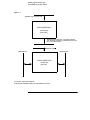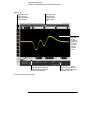
1
Infiniium 9000A Series
Oscilloscope
User’s Guide
Publication number 54904-97006
October 2009
©
Copyright Agilent Technologies 2009
All Rights Reserved
In This Book
This book gives you the information you need to begin using the Infiniium 9000 Series
oscilloscope. The information contained in this guide covers the basic controls and
will let you quickly become comfortable with the instrument. The help system
embedded into the oscilloscope GUI (see Chapter 4) is much more complete and
detailed and should be your main source of information after becoming acquainted
with the oscilloscope.
This guide contains four chapters:
Setting up the Oscilloscope Chapter 1 contains inspection, power requirements, air
flow, and setup information.
Working in Comfort Chapter 2 contains recommendations for working
comfortably and safely while operating the Infiniium Oscilloscope.
Using the Oscilloscope Chapter 3 gives an overview of the front panel and the
graphical user interface, and tells you how to perform basic operations with the
oscilloscope.
Using the Built-In Information System Chapter 4 describes the built-in
information system contents and navigation. The built-in information system contains
all of the information that is generally found in a User’s Guide.
• For detailed information on how the oscilloscope makes measurements and how
to use the oscilloscope, see the built-in information system in the oscilloscope.
• For information on programming the oscilloscope using a computer with a GPIB
interface card or LAN interface card, see the Programmer’s Reference for your
model number oscilloscope found in the Infiniium Information System.
• For information on testing and servicing the oscilloscope, see the Service Guide
manual for your model number oscilloscope found in Infiniium Information
System.
Contents
1 Setting Up the Oscilloscope
To inspect package contents 1-3
To inspect options and accessories 1-4
Technical Specifications 1-8
To position for proper airflow 1-13
To connect power 1-15
To connect the mouse, the keyboard, a LAN cable, a USB device, and a
printer 1-16
To connect oscilloscope probes 1-18
To tilt the oscilloscope upward for easier viewing 1-20
To turn on the oscilloscope 1-21
To turn off the oscilloscope 1-22
To verify basic operation for the 9000A series oscilloscope 1-23
Installing application programs on Infiniium 1-25
Changing Windows System Settings 1-26
To clean the oscilloscope 1-27
2 Working in Comfort
About Repetitive Strain Injury 2-3
Mice and Other Input Devices 2-4
3 Using the Oscilloscope
Front Panel 3-4
Run Controls 3-6
Horizontal Controls 3-6
Trigger Controls 3-6
Vertical Controls 3-7
Marker and Measurement Controls 3-7
To set the oscilloscope to a known starting condition 3-8
To start and stop waveform acquisition 3-9
To clear the waveform display 3-10
To turn an analog channel on or off 3-11
To turn the digital channels on or off 3-12
To adjust the analog channels’ vertical scale and offset 3-13
To adjust horizontal scale and horizontal position 3-14
To magnify a part of the waveform using Zoom 3-15
To set the oscilloscope to trigger on an edge 3-16
To use the markers 3-17
To use the quick measurements 3-18
To enable or disable the touch screen 3-19
To reinitialize the oscilloscope 3-20
Graphical User Interface 3-22
To perform basic user interface operations 3-29
To select a command from the menu bar 3-33
To select a command from a context-sensitive menu 3-34
To start and stop waveform acquisition 3-37
Contents-1
Contents
To clear the waveform display 3-38
To print the screen 3-39
To change waveform brightness 3-40
To turn a channel on or off 3-41
To adjust the vertical offset 3-42
To adjust vertical scaling 3-44
To access the channel setup 3-45
To set the horizontal reference point 3-46
To adjust horizontal scale 3-47
To adjust horizontal position 3-48
To access the horizontal setup 3-49
To zoom on a section of the waveform 3-50
To move the markers using the graphical interface
To make a measurement on a waveform 3-54
To access the trigger setup 3-56
To set an edge trigger 3-57
To set dialog box preferences 3-58
To recover your Infiniium hard disk 3-59
4 Using the Built-In Information System
To access the information system 4-3
To access context-sensitive information
Contents-2
4-7
3-52
1
Setting Up the Oscilloscope
Setting Up the Oscilloscope
This chapter shows you how to set up your Infiniium oscilloscope, connect
power and accessories, and verify general operation.
1-2
Setting Up the Oscilloscope
To inspect package contents
To inspect package contents
o Inspect the shipping container for damage.
Keep a damaged shipping container or cushioning material until you have inspected
the contents of the shipment for completeness and have checked the oscilloscope
mechanically and electrically.
o Inspect the oscilloscope.
• If there is mechanical damage or a defect, or if the oscilloscope does not operate
properly or does not pass performance tests, notify your Agilent Technologies
Sales Office.
• If the shipping container is damaged, or the cushioning materials show signs of
stress, notify the carrier and your Agilent Technologies Sales Office. Keep the
shipping materials for the carrier’s inspection. The Agilent Technologies Sales
Office will arrange for repair or replacement at Agilent’s option without waiting
for claim settlement.
o Verify that you received the following items in the Infiniium Oscilloscope
packaging.
•
•
•
•
•
•
Infiniium Oscilloscope
Mouse
Touchscreen Stylus
Front Panel Cover
N2873A 10:1 Divider Passive Probe per Scope Channel
Channel Flying Lead Set Logic Probe, MSO Cable, and Calibration Fixture (MSO
models only)
• Probe Accessory Pouch (mounts on rear of oscilloscope)
• Agilent I/O Libraries Suite 15.0
• Localized Power Cord
• Keyboard
If anything is missing, contact your nearest Agilent Technologies Sales Office. If the
shipment was damaged, contact the carrier, then contact the nearest Agilent
Technologies Sales Office.
1-3
Setting Up the Oscilloscope
To inspect options and accessories
To inspect options and accessories
o Verify that you received the options and accessories you ordered and that none
were damaged.
If anything is missing, contact your nearest Agilent Technologies Sales Office. If the
shipment was damaged, or the cushioning materials show signs of stress, contact the
carrier and your Agilent Technologies Sales Office.
Some accessories that will enhance your work with the 9000A series oscilloscopes
are listed in table 1-1.
Table 1-1
Accessories and Software for the 9000A Series Infiniium Oscilloscopes
Agilent Model
Number
Description
Probes
1131A
3.5 GHz InfiniiMax Probe Amplifier
1132A
5 GHz InfiniiMax Probe Amplifier
1134A
7 GHz InfiniiMax Probe Amplifier
1168A
10 GHz InfiniiMax II Probe Amplifier
1169A
12 GHz InfiniiMax II Probe Amplifier
E2668A
InfiniiMax Single-ended Connectivity Kit
E2669A
InfiniiMax Differential Connectivity Kit
N5381A
12 GHz Solder-in Differential Probe Head
N5382A
12 GHz Differential Browser Probe Head
N5380A
SMA Probe Head
1156A
1.5 GHz Single-ended Active Probe
1157A
2.5 GHz Single-ended Active Probe
1158A
4 GHz Single-ended Active Probe
N2774A
50 MHz Current Probe
N2775A
Probe Power Supply for N2774A
E2697A
High Impedance Adapter, option 807 (includes one 10073C passive
probe)
54006A
6 GHz probe, 10:1 (500 Ω) or 20:1 (1 kΩ), .25 pf
E2655A
Additional probe deskew and performance verification kit
1-4
Setting Up the Oscilloscope
To inspect options and accessories
Agilent Model
Number
Description
N2870A Series
Passive Probe Family (Deluxe, Fine Pitch, and General Purpose
Accessory Kits are available as well)
Rackmount Kit
N2902A or Option
1CM
Rackmount Kit, option 1CM
Software Applications and Upgrades
Option A6J
ANSI Z540 Compliant Calibration
Option-001
RS-232/UART Triggering and Decode - installed
Option-002
EZJIT jitter analysis software - installed
Option-003
High-speed SDA and Clock Recover - installed
Option-004
EZJIT Plus jitter analysis software - installed
Option-005
USB Triggering and Decode - installed
Option-006
PCIe 1.1 Triggering and Decode - installed
Option-007
I2C/SPI Triggering and Decode - installed
Option-008
CAN/Flexray Triggering and Decode - installed
Option-009
InfiniiScan - installed
Option-010
User Defined Function - installed
Option-011
App Remote Programming Interface - installed
Option-012
Infiniium Signal Equalization - installed
Option-013
InfiniiSim Waveform Transformation Toolset (Basic) - installed
Option-014
InfiniiSim Waveform Transformation Toolset (Advanced) - installed
Option-015
Power Measurement application software - installed
Option-016
Xilinx FPGA dynamic probe - installed
Option-017
Altera FPGA dynamic probe - installed
Option-018
RS-232, SPI, and I2C Triggering and Decode Bundle - installed
Option-021
Ethernet compliance application - installed
Option-029
USB2.0 compliance application - installed
Option-031
DDR1 validation application - installed
Option-032
DDR2 validation application - installed
Option-033
DDR3 validation application - installed
Option-040
User Definable Application
1-5
Setting Up the Oscilloscope
To inspect options and accessories
Agilent Model
Number
Description
DSO9000A-820
DVD-RW with USB connection
N2902A
9000A Series rackmount kit
N2903
Additional removable hard disk drive
Gemstar 5000
Available from www.gemstarmfg.com
custom-molded case
Stand-alone SW Products
N5464B
USB Triggering and Decode Application for Infiniium 9000A Series
N5463B
PCIe Triggering and Decode Application for Infiniium 9000A Series
N5462B
RS-232 / UART Triggering and Decode Application for Infiniium
9000A Series
N5391B
I2C/SPI Triggering and Decode Application for Infiniium 9000A
Series
E2681A
EZJIT Jitter Analysis Software
N5384A
High-speed Serial Data Analysis and Clock Recovery
N5400A
EZJIT Plus Jitter Analysis Software
N8803A
CAN/Flexray Triggering and Decode Application for Infiniium 9000A
Series
N5415A
InfiniiScan
N5430A
User Defined Function
N5452A
Application Remote Programming Interface
N5461A
Infiniium Signal Equalization
N5465A 001
InfiniiSim Waveform Transformation Toolset (Basic)
N5465A 002
InfiniiSim Waveform Transformation Toolset (Advanced)
U1882A
Power Measurement Application Software
N5397A
Xilinx FPGA Dynamic Probe
N5433A
Altera FPGA Dynamic Probe
N5392A
Ethernet Compliance Application
N5416A
USB 2.0 Compliance Application
U7233A
DDR1 Validation Application
N5413A
DDR2 Validation Application
1-6
Setting Up the Oscilloscope
To inspect options and accessories
Agilent Model
Number
Description
U7231A
DDR3 up to 800 MHz Validation Application
N5467A
User Definable Application
E2625A
Communication Mask Test Kit
E2682A
VoiceControl Software for Infiniium Oscilloscopes
DSO to MSO upgrades are available and are listed in table 1-2.
Table 1-2
DSO to MSO upgrades for Infiniium 9000A Series Oscilloscopes
Agilent Model Number Description
N2901D
DSO9064A to MSO9064A
N2901A
DSO9104A to MSO9104A
N2901B
DSO9254A to MSO9254A
N2901C
DSO9404A to MSO9404A
Acquisition memory upgrades are available to protect your Infiniium oscilloscope
investment when acquisition memory needs change. You can install memory
upgrades without opening the oscilloscope case or requiring on-site service.
Acquisition memory upgrades are listed in table 1-3.
Table 1-3
Acquisition memory upgrades for Infiniium Oscilloscopes
Agilent Model Number Description (memory is 2x in 2-channel mode)
N2900A-020
Upgrade to 20 MPts
N2900A-050
Upgrade to 50 MPts
N2900A-100
Upgrade to 100 MPts
N2900A-200
Upgrade to 200 MPts
N2900A-500
Upgrade to 500 MPts
1-7
Setting Up the Oscilloscope
Technical Specifications
Technical Specifications
Below are the technical specifications for the Infiniium 9000A Series oscilloscopes.
Vertical: Analog Channels
Analog Bandwidth (-3 db) 50 Ω*
9064A: 600 MHz
9104A: 1.0 GHz,
9254A: 2.5 GHz,
9404A: 4.0 GHz
Calculated Rise Time / Fall Time, 9064A; 540 ps
10%-90% at 50 Ω
9104A: 253 ps,
9254A: 142 ps,
9404A: 85 ps
Calculated Rise Time / Fall Time, 9064A: 310 ps
20%-80% at 50 Ω
9104A: 174 ps,
9254A: 98 ps,
9404A: 59 ps
Input channels
DSO models: 4 analog
MSO models: 4 analog + 16 digital
Input impedance*
50 Ω \2.5%, 1 MΩ \1% (11 pF typical)
Input sensitivity
1 ΜΩ: 1 mV/div to 5 V/div
50 Ω: 1 mV/ to 1 V/div
Input coupling
1 ΜΩ: AC (3.5 Hz), DC
50 Ω: DC
Hardware bandwidth limit
20 MHz on 1 ΜΩ input only
Vertical resolution**
8 bits, >=12 bits with averaging
Channel-to-channel isolation
DC to 50 MHz: 50 dB
>50 MHz to 1 GHz: 40 dB
>1 GHz to 4 GHz: 25 dB
\2% of full scale at full resolution on channel scale \5 oC from cal temp
DC gain accuracy**
*Denotes warranted specification, all others are typical. Specifications are valid only after a 30 minute warm-up period
and \5 oC from firmware calibration temperature.
**Vertical resolution for 8 bits = 0.4% of full scale, for 12 bits = 0.024% of full scale
***Calculated from the bandwidth
1-8
Setting Up the Oscilloscope
Technical Specifications
Vertical: Analog Channels
Maximum input voltage*
Offset range
1 ΜΩ: 150 Vrms or dc, CAT I, \250 V (dc + ac) in ac coupling
50 Ω: 5 Vrms
1 MΩ
(vertical sensitivity: offset)
1 mV to < 10 mV/div: \2 V
10 mV to < 20 mV/div: \5 V
20 mV to <100 mV/div: \10 V
100 mV to 1 V/div: \20 V
1 V to 5 V/div: \100 V
50 Ω
\12 div or \4 V, whichever is smallest
\(1.25% of channel offset + 1% of full scale + 1 mV)
Offset accuracy**
Dynamic range
1 ΜΩ: \8 div from center screen
50 Ω: \8 div from center screen
DC voltage measurement
Dual Cursor: \[(dc gain accuracy) + resolution]
accuracy*, **, ***
Single Cursor: \[(dc gain accuracy) + offset accuracy + (resolution/2)]
*Denotes warranted specification, all others are typical. Specifications are valid only after a 30 minute warm-up period
and \5 oC from firmware calibration temperature.
**Vertical resolution for 8 bits = 0.4% of full scale, for 12 bits = 0.024% of full scale
***Calculated from the bandwidth
Vertical: Digital Channels (on all MSO models)
Input channels
16 digital channels
Threshold groupings
Pod 1: D7 - D0
Pod 2: D15 - D8
\8.00 V in 10 mV increments
User-defined threshold range
\40 V peak, CAT I
Maximum input voltage
\(100 mV + 3% of threshold setting)
Threshold accuracy
\10 V about threshold
Input dynamic range
Minimum input voltage swing
500 mV peak-to-peak
Input impedance (flying leads)
100 KΩ \2% (app. 8 pF) at probe tip
Resolution
1 bit
1-9
Setting Up the Oscilloscope
Technical Specifications
Horizontal
Channel-to-channel skew (digital)
2 ns typical
Glitch detect
>= 2.0 ns
Main time base range
5 ps/div to 20 s/div
Horizontal position range
0 to \200 s
Delayed sweep range
1 ps/div to current main time base setting
Resolution
1 ps
\(0.4 + 0.5*YrsSinceCal)) ppm pk
Time scale accuracy*
*Denotes warranted specification, all others are typical. Specifications are valid only after a 30 minute warm-up period
and \5 oC from firmware calibration temperature.
Acquisition
Maximum real-time sample rate
4 ch x 10 GSa/s or 2 ch x 20 GSa/s
*The DSO/MSO 9064A model has a maximum real-time sampling rate of 5
GSa/s (4 channel mode), 10 GSa/s (2 channel mode)
Memory depth per channel
Standard: 10 Mpts on 4 channels, 20 Mpts on 2 channels
Option 20M: 20 Mpts on 4 channels, 40 Mpts on 2 channels
Option 50M: 50 Mpts on 4 channels, 100 Mpts on 2 channels
Option 100: 100 Mpts on 4 channels, 200 Mpts on 2 channels
Option 200: 200 Mpts on 4 channels, 400 Mpts on 2 channels
Option 500: 500 Mpts on 4 channels, 1 Gpts on 2 channels
Maximum real-time sample rate (digital 2 GSa/s
channels)
Maximum memory depth per channel 128 Mpts with 2 GSa/s, 64 Mpts with sampling < 2 GSa/s (single mode)
(digital channels)
64 Mpts with 2 GSa/a, 32 Mpts with sampling < 2 GSa/s (repetitive mode)
Minimum width glitch detection (digital 2 ns
channels)
1-10
Setting Up the Oscilloscope
Technical Specifications
Computer System
Operating System
CPU
PC system memory
Drives
LXI compliance
General Characteristics
Temperature
Humidity (non-condensing)
Altitude
Vibration
Power
Weight
Dimensions (with feet retracted)
Safety
Windows XP Pro
Intel Celeron M530 1.733 GHz microprocessor
2 GB
>= 250 GB internal hard drive (optional removabel hard drive), external DVDRW drive (optional)
LXI Class C
Operating: 5 oC to 40 oC
Non-operating: -40 oC to 70 oC
Operating: Up to 95% relative humidity at 40 oC
Non-operating: Up to 90% relative humidity at 65 oC
Operating: Up to 4,000 meters (12,000 feet)
Non-operating: Up tp 15,300 meters (50,000 feet)
Operating: Random vibration 5-500 Hz, 10 minutes per axis, 0.21 g (rms)
Non-operating: Random vibration 5-500 Hz, 10 minutes per axis, 2.0 g (rms);
resonant search 5-500 Hz, swept sine, 1 octave/minute sweep rate, (0.50 g), 5
minute resonant dwell at 4 resonances per axis
100-120 V, 50/60/400 Hz
100-240 V, 50/60 Hz
Max power dissipated: 375 W
Net: 11.8 kg (26 lbs) Shipping: 17.8 kg (39 lbs)
Height: 12.9 in (33 cm)
Width: 16.8 in (43 cm)
Depth: 9 in (23 cm)
Meets IEC1010-1 +A2, CSA certified to C22.2 No. 1010.1, Self certified to UL
3111
1-11
Setting Up the Oscilloscope
Technical Specifications
General Characteristics
Connections
4 BNC analog channel inputs
1 Digital channels input
1 LAN 10/100/1000Base-Tport
1 Parallel printer port
1 Serial printer port
Probe compensation connection
7 Host USB 2.0 port, 1 Device USB 2.0 port
2 PS/2 connections
1 Aux Out BNC
1 Time base reference output BNC
1 Time base reference input BNC
1 VGA connection
speaker/microphone connections
AC power cord connection
Measurement Category I; Warning: Do not use this equipment for
measurements within measurement categories II, III, and IV
30 dB
Measurement Category
Typical Operator Noise
1-12
Setting Up the Oscilloscope
To position for proper airflow
To position for proper airflow
!
1 Position the oscilloscope where it will have sufficient clearance for airflow
around the top, back, and sides (see diagram on next page). Also, only place
the oscilloscope on a hard surface so as not to block the airflow underneath
the oscilloscope (for example, a piece of paper or carpet could block these
fans and cause the instrument to overheat).
1-13
Setting Up the Oscilloscope
To position for proper airflow
Figure 1-1
Minimum top clearance 0 mm
Infiniium 9000A Series
oscilloscope
(front view)
Minimum bottom clearance : No intrusion into the
space under the oscilloscope as defined by the feet. Feet
must rest on hard surface.
Rear Panel
Minimum 75 mm
Minimum 25.4
Minimum 25.4
Infiniium 9000A Series
oscilloscope
Top View
(top view)
The airflow requirement is 300 cfm
Positioning the Infiniium Oscilloscope with Sufficient Clearance
1-14
Setting Up the Oscilloscope
To connect power
To connect power
1 Position the oscilloscope so that it is not difficult to unplug the power cord.
2 Connect the power cord to the side panel of the oscilloscope and then to a
suitable ac voltage source (100 to 120 V, 50/60/400 Hz and 100 to 240 V, 50/
60 Hz for the 9000A series). The power cord serves as the main disconnecting
device. Please refer to page 1-12 for rating specifications.
Maximum power dissipation: 9000A series is 375 W
The oscilloscope power supply automatically adjusts for line input
voltages in the range 100 to 240 VAC. Therefore, you do not need to
adjust an input line voltage setting. The line cord provided is matched
by Agilent Technologies to the country of origin of the order.
You should regularly check the condition of the power cord.
AC power cord
plugs into here
1-15
Setting Up the Oscilloscope
To connect the mouse, the keyboard, a LAN cable, a USB device, and a printer
To connect the mouse, the keyboard, a LAN cable, a USB
device, and a printer
See Figure 1-2 on the next page for the location of the side panel connectors described
below.
Mouse
The mouse can be plugged into either a USB port or into a PS2 port. There are several
USB connectors on the front panel or the side panel of the oscilloscope that can be
used. When using the PS2 port, the mouse must be plugged in prior to turning on
power to the oscilloscope
Keyboard
The keyboard can be plugged into either a USB port or into a PS2 port. There are
several USB connectors on the front panel or the side panel of the oscilloscope that
can be used. When using the PS2 port, the keyboard must be plugged in prior to turning
on power to the oscilloscope.
LAN Cable
Connect your LAN cable to the RJ-45 connector on the side panel of the oscilloscope.
After you have connected to the LAN card, you must set up the network. Before
you try to setup your network, you should exit the oscilloscope application. If you
do not know how to setup a network in Windows XP, see your network
administrator or use the Windows XP on-line help.
USB
Connectors
Printer Cable
Side panel USB connectors can be used for any USB devices. There are also three
USB connectors in the lower right-hand corner of the front panel.
If you have a parallel (Centronics) printer, you will need a parallel printer cable.
Connect cable to parallel port on side panel of oscilloscope.
If you have a serial printer, you will need a 9-pin to 25-pin serial printer cable. Some
printers may require other cable configurations, but the oscilloscope has a 9-pin serial
connector. Connect cable into the RS-232 port.
1-16
Setting Up the Oscilloscope
To connect the mouse, the keyboard, a LAN cable, a USB device, and a printer
Figure 1-2
Mouse PS/2 port
Keyboard PS/2 Port
Removable
Hard Drive
Serial printer
port
XGA video
output
Parallel printer
port
USB ports
LAN port
USB cable
AC power
input
Side Panel
1-17
Setting Up the Oscilloscope
To connect oscilloscope probes
To connect oscilloscope probes
There are optional Infiniium oscilloscope probes, such as the InfiniiMax 1130A and
1168A/69A series probes, that connect to the oscilloscope differently than other
oscilloscope probes. Use the following steps to connect these snap-on probes to the
oscilloscope.
1 Attach the probe connector to the desired oscilloscope channel or trigger input.
Push it straight on until it latches into place.
Figure 1-3
Digital
channels
input
4 analog input channels where probes are
connected
1-18
Setting Up the Oscilloscope
To connect oscilloscope probes
2 Connect the probe to the circuit of interest using the browser or other probing
accessories.
Figure 1-4
Probing the Circuit
3 To disconnect the probe, push the small latch on top of the probe connector
to the left, then pull the connector body away from the front panel of the
oscilloscope without twisting it.
CAUTION
CAUTION
Do not attempt to twist the snap-on probes on or off the oscilloscope’s BNC connector.
Twisting the probe connector body will damage it.
!
For the 9000A series oscilloscopes do not exceed the maximum input voltage
rating. The maximum input voltage for the 50 Ω inputs is ±5 Vpeak, CAT I and for
the 1 MΩ inputs, it is 150 Vrms (or dc), CAT I, ±250 V (dc + ac) in ac coupling.
1-19
Setting Up the Oscilloscope
To tilt the oscilloscope upward for easier viewing
To tilt the oscilloscope upward for easier viewing
1 Lift up the front of the oscilloscope, grasp one of the plastic feet on either side,
and pull it down and forward until it latches into place. Repeat for the other
side.
Figure 1-5
Latching the Oscilloscope Front Feet
1-20
Setting Up the Oscilloscope
To turn on the oscilloscope
To turn on the oscilloscope
The first time that you turn on the oscilloscope, you will need to have a mouse
connected. The mouse is needed to accept the Microsoft end-user license
agreement for Windows XP Pro.
1 Depress the power switch in the lower left-hand corner of the oscilloscope
front panel.
Figure 1-6
power switch
Turning on the Oscilloscope
After a short initialization period, the oscilloscope display appears. The oscilloscope
is ready to use.
2 You can connect and disconnect probes and BNC cables while the
oscilloscope is turned on.
1-21
Setting Up the Oscilloscope
To turn off the oscilloscope
To turn off the oscilloscope
1 Momentarily depress the power switch at the lower left-hand corner of the
oscilloscope front panel. The oscilloscope will go through a normal Windows
shutdown process.
1-22
Setting Up the Oscilloscope
To verify basic operation for the 9000A series oscilloscope
To verify basic operation for the 9000A series oscilloscope
1 Connect one end of the calibration cable using SMA to precision BNC
adaptors to channel 1.
2 Connect the other end of the calibration cable to the front panel connector with
the square wave label.
Figure 1-7
Front panel
connector
with square
wave label
Verifying Basic Oscilloscope Operation for 9000A Series Oscilloscopes.
3 Press the Default Setup key on the front panel.
The display will pause momentarily while the oscilloscope is configured to its default
settings.
4 Press the Autoscale key on the front panel.
1-23
Setting Up the Oscilloscope
To verify basic operation for the 9000A series oscilloscope
The display will pause momentarily while the oscilloscope adjusts the sweep speed
and vertical scale. You should then see a square wave with peak-to-peak amplitude
of approximately 5 divisions and about four cycles on screen. If you do not see the
waveform, ensure your power source is adequate, the oscilloscope is properly
powered-on, and the probe is connected securely to the front-panel channel input BNC
and to the probe calibration output.
5 Move the mouse around the mouse surface and verify that the on screen pointer
follows the mouse movement.
6 Touch the pointer of the touch screen stylus to the surface of the screen and
move it around while verifying that the pointer follows the movement. Ensure
that the front panel Touchscreen button is illuminated (symbolizing that the
touch screen is enabled). You do not need to use the stylus in many instances
when controlling the oscilloscope via the touch screen - a finger is effective
as well.
1-24
Setting Up the Oscilloscope
Installing application programs on Infiniium
Installing application programs on Infiniium
Infiniium is an open Windows system. This allows you to install your own application
software. Agilent has verified that the following applications are compatible with the
Infiniium oscilloscope application.
• Agilent Vector Signal Analysis
• Agilent VEE Pro
• Amherst Systems Oscilloscope Tools
• Microsoft Office 2000, 2003, 2007
• MathWorks MATLAB
• Mathsoft MathCad 2001i
• McAfee VirusScan
• Symantec Norton AntiVirus
Before installing any software, you should exit the oscilloscope application.
If you install an application other than those which Agilent has tested, it is possible
that it could break the oscilloscope application. This would potentially require you
to recover the oscilloscope hard drive using the hard drive’s hidden recovery partition.
1-25
Setting Up the Oscilloscope
Changing Windows System Settings
Changing Windows System Settings
Before changing any Windows System settings outside of the oscilloscope
application you should Exit the oscilloscope application.
There are several Windows System settings that can be changed to suit your own
personal preferences. However, there are some system settings that you should avoid
changing because it will interfere with the proper operation of the oscilloscope.
•
•
•
•
•
Do not change the Power Options.
Do not change the System Properties Hardware Tab settings.
Do not change the Regional and Language Options Advanced Tab settings.
Do not remove Fonts.
Display Settings
• Do not change the screen resolution or the color quality from Highest (32 bit).
• Do not change the Font size to Extra Large.
• Do not use a Menu font size greater than 14 points.
• Do not use the Administrative Tools to enable or disable Internet Information
Services (Web Server). Use the Infiniium Web Control dialog box to enable
or disable the Web Server.
• Do not delete or modify the InfiniiumAdmin user account.
1-26
Setting Up the Oscilloscope
To clean the oscilloscope
To clean the oscilloscope
• Clean the oscilloscope with a soft cloth dampened with a mild soap and water
solution.
CAUTION
Do not use too much liquid in cleaning the oscilloscope. Water can enter the Infiniium
front panel, damaging sensitive electronic components.
1-27
Setting Up the Oscilloscope
To clean the oscilloscope
1-28
2
Working in Comfort
Introduction
To optimize your comfort and productivity, it is important that you set up your
work area correctly and use your Infiniium oscilloscope properly. With that
in mind, we have developed some setup and use recommendations for you to
follow based on established ergonomic principles.
Improper and prolonged use of keyboards and input devices are among those
tasks that have been associated with repetitive strain injury (RSI) to soft tissues
in the hands and arms. If you experience discomfort or pain while using the
oscilloscope, discontinue use immediately and consult your physician as soon
as possible. For more information on RSI you may wish to consult the About
Repetitive Strain Injury section.
Please study the recommendations offered here in this chapter. Included there
are references to relevant parts of international standards, regulations and
guidelines, such as ISO 9241 and the European Community Display Screen
Equipment directive. You may also wish to consult your employer’s human
resources department or other relevant departments for guidance specific to
your company.
2-2
Working in Comfort
About Repetitive Strain Injury
About Repetitive Strain Injury
What is RSI?
What causes RSI?
What if I experience
discomfort?
Because your comfort and safety are our primary concern, we strongly recommend
that you use the Infiniium oscilloscope in accordance with established ergonomic
principles and recommendations. Scientific literature suggests that there may be a
relationship between injury to soft tissues—especially in the hands and arms—and
prolonged improper use of keyboards or other equipment requiring repeated motions
of the hands and forearms. This literature also suggests that there are many other risk
factors that may increase the chance of such injury, commonly called Repetitive Strain
Injury.
Repetitive Strain Injury (RSI—also known as cumulative trauma disorder or repetitive
motion injury) is a type of injury where soft tissues in the body, such as muscles,
nerves, or tendons, become irritated or inflamed. RSI has been a reported problem
for those who perform repetitive tasks such as assembly line work, meatpacking,
sewing, playing musical instruments, and computer work. RSI also has been observed
in those who frequently engage in activities such as carpentry, knitting, housework,
gardening, tennis, windsurfing and lifting children.
The specific causes of RSI have not been established. Nevertheless, the incidence of
RSI has been associated with a variety of risk factors, including:
• Too many uninterrupted repetitions of an activity or motion.
• Performing an activity in an awkward or unnatural posture.
• Maintaining static posture for prolonged periods.
• Failing to take frequent short breaks.
• Other environmental and psychosocial factors.
In addition, there have been reports associating the occurrence of RSI with the use of
keyboards, mice, and other input devices. Also, certain medical conditions, such as
rheumatoid arthritis, obesity and diabetes, may predispose some people to this type
of injury.
If you are experiencing any discomfort, seek professional medical advice
immediately. Typically, the earlier a problem is diagnosed and treated, the easier it
is to resolve.
2-3
Working in Comfort
Mice and Other Input Devices
Mice and Other Input Devices
Various aspects of using mice and other input devices may increase your risk of
discomfort or injury. Observing the following recommendations may reduce that risk.
• Try to keep your hand, wrist, and forearm in a neutral position while using your
mouse or other input device.
• If you use your thumb to rotate the ball on a trackball or spaceball, keep it in a
relaxed, natural shape, and maintain a neutral posture in your hand, wrist, and
forearm.
• Hold the mouse gently by draping your fingers over it. Keep your hand relaxed
and fingers loose. Do not grip the mouse tightly.
• It takes very little pressure or force from your fingers to activate the buttons or
scroll wheel on your mouse, scrolling mouse, trackball, or other input device.
Using too much force can place unnecessary stress on the tendons and muscles in
your hands, wrists, and forearms.
• If you are using a scrolling mouse, be sure to keep your fingers and hand in a
relaxed, neutral position when activating the scroll wheel. Also, this type of mouse
features software that can minimize the number of mouse movements or button
clicks.
• When using a mouse, trackball, or other input device, position it as close to the
keyboard as possible, and keep it at the same level as you do not have to stretch
while using it.
• Be sure to keep your mouse and trackball clean. Regular removal of accumulated
dust and dirt helps ensure proper tracking and reduces unnecessary hand and wrist
motions.
2-4
3
Using the Oscilloscope
Using the Oscilloscope
The topics covered in this chapter are very basic controls. For more detailed
explanations of controls not found in this chapter, consult the built-in
information system loaded on your oscilloscope (Help > Contents).
The Infiniium Oscilloscope is designed to be easy to use.
• The familiar front-panel oscilloscope interface with knobs and keys is
optimized for the most common kinds of troubleshooting tasks and basic
measurements. See “Using the Front Panel” on page 3-3.
• The graphical interface with menus, windows, dialogs, and toolbars
provides easy logical access to dozens of configuration and analysis tools,
making it easy for you to set up and make the most complex measurements.
The interface also allows you to use the Infiniium oscilloscope’s built-in
information system, which gives detailed information on using the
oscilloscope to make measurements. See “Using the Graphical Interface”
on page 3-21.
3-2
Using the Oscilloscope
Using the Front Panel
The Infiniium Oscilloscope front panel has been designed to give you direct
access to the functions needed to perform the most common measurements
needed in troubleshooting, using a traditional oscilloscope interface. Knobs
and keys are included to enable direct setting of vertical and horizontal
parameters. In addition, the front panel has a set of LED (Light-Emitting
Diode) indicators; by using these and the display, you can assess the
configuration of the oscilloscope at a glance—there is no need to enter a series
of keystrokes to navigate through complex menus.
You can also push on many of the front panel knobs to activate various modes
such as vernier scaling (fine scaling).
The Infiniium Oscilloscope uses color consistently throughout the front panel
and user interface. For example, the color for channel 1 is the same color as
the waveform for channel 1. All the configuration items and values related
to channel 1 are displayed in the same color.
3-3
Using the Oscilloscope
Front Panel
Front Panel
Figure 3-1 shows a typical Infiniium 9000A Series oscilloscope front panel.
Figure 3-1
Selection knob (push to toggle selection)
Run/Stop control section
Horizontal controls
(time/div, position, etc.)
Trigger controls
Turn digital channels on/off
Turn serial decode on/off
Color coded controls for
each analog oscilloscope
channel
Infiniium Oscilloscope Front Panel
3-4
Using the Oscilloscope
Front Panel
Using the front panel, you can configure the Infiniium oscilloscope for most
troubleshooting tasks. The control categories are:
• Run controls
• Horizontal controls
• Trigger controls
• Vertical controls
• Measure controls
3-5
Using the Oscilloscope
Run Controls
Run Controls
Using the Run controls, you control whether the oscilloscope is running or stopped.
You can also put the oscilloscope into Single mode where only one acquisition is
acquired before the oscilloscope stops.
Horizontal Controls
Using the horizontal controls, you configure the oscilloscope’s horizontal scale
(seconds per division) and horizontal position of the waveform. You can also view a
magnified section of the waveform using the Zoom window, which uses software to
expand part of the acquisition memory.
Several other keys are in this section that do not directly deal with horizontal controls.
For example, the Autoscale key allow you to reset the oscilloscope to its default setup
and automatically configure the oscilloscope for the current input signals. Also, the
clear display control erases the waveforms from the display and resets such things as
measurement statistics and averaging. The touch control enables or disables the touch
screen. The Default Setup key returns the oscilloscope to a knows state.
Trigger Controls
Using the trigger controls, you set the conditions on which the oscilloscope will trigger
and acquire an input signal. You can set up a variety of trigger conditions. Edge and
advanced triggers can be selected from the front panel, and the parameters for edge
triggering can be set up here as well. The advanced trigger parameters must be set
up using the graphical interface.
Trigger configuration settings you make using the graphical interface are reflected in
the front-panel status indicators, and will remain set unless you change them (either
using the front panel or the graphical interface) or press the Default Setup key. See
“Using the Graphical Interface” on page 3-21 for information on accessing the
graphical interface.
3-6
Using the Oscilloscope
Vertical Controls
Vertical Controls
Using the vertical controls, you set the vertical scaling (volts per division) and vertical
offset. You can also turn the display on or off for a particular channel.
Additionally, this section has a set of LEDs per channel that tell you what the imput
impedance is for the channel, what the coupling is for the channel, and whether or not
Bandwidth Limit is enabled.
Marker and Measurement Controls
Using the marker and measurement controls, you control two sets of markers within
the oscilloscope graticule. You use markers to make more accurate measurements of
waveform events than you could make visually. Both time and voltage differences
between the markers are updated continuously on the screen. By default, the markers
track the source waveform. Voltage measurements from the markers are the value of
the waveform at the time set with the marker position control.
The Multipurpose key can be customized in the GUI to perform a variety of operations
(under Utilities > Customize Multipurpose). Pressing this key will then carry out the
operation you specify.
3-7
Using the Oscilloscope
To set the oscilloscope to a known starting condition
To set the oscilloscope to a known starting condition
• Press the Default Setup key.
You can set up the oscilloscope for many different kinds of complex measurements.
To easily reset the oscilloscope to a known measurement configuration, use the
Default Setup key.
If you use the Default Setup key, you can select Undo Default Setup from the Control
menu to return the oscilloscope to its original configuration.
Save the Current Oscilloscope Configuration
Before using Default Setup, you may want to save the current oscilloscope
configuration for later use. See the built-in information system (described in
chapter 4) for instructions on saving and recalling setups, and for information
on the exact configuration that is set when you press Default Setup.
3-8
Using the Oscilloscope
To start and stop waveform acquisition
To start and stop waveform acquisition
The Run/Stop key is used to start and stop the acquisition of waveforms. If the key is
illuminated green then Infiniium is acquiring waveforms. If the key is illuminated
red then Infiniium is not acquiring waveforms.
• To start a waveform acquisition, press the Run/Stop key if the key is
illuminated red.
The oscilloscope begins acquiring data. When it receives a trigger signal, it finishes
acquiring data, updates the display, then starts another acquisition cycle if it is in
triggered (Trig’d) or auto trigger (Auto) mode.
• To stop waveform acquisition, press the Run/Stop key if the key is illuminated
green.
The oscilloscope stops acquiring data. Whatever data was last acquired remains on
the screen.
• Press the Single key to acquire a single acquisition and then stop the
oscilloscope.
3-9
Using the Oscilloscope
To clear the waveform display
To clear the waveform display
• Press the Clear Display key.
The oscilloscope clears the waveform display. If the oscilloscope is in Run mode and
is receiving triggers, it will update the display as it collects new waveform data.
Clearing the waveform display also resets averaging, infinite persistence, color grade
persistence, histogram, mask testing, and measurement statistics.
3-10
Using the Oscilloscope
To turn an analog channel on or off
To turn an analog channel on or off
• To turn an analog channel on, press the channel number key in the Vertical
section until it is illuminated. To turn it off, press the channel number key
again.
If you are not using a particular channel, you can turn it off. This simplifies the
waveform display and also increases the display update rate. While a channel is turned
off, data acquisition continues for that analog channel. Thus, you can still use the
analog channel as a source for functions.
Using an Analog Channel as External Trigger
Any analog channel can be used as a trigger source. If you need an external
trigger but do not need all analog channels, you can use an analog channel as
an external trigger without displaying it by turning the analog channel display
off.
3-11
Using the Oscilloscope
To turn the digital channels on or off
To turn the digital channels on or off
• To turn the digital channels on, press the Digital key on the front panel. To
turn them off, press the key again.
3-12
Using the Oscilloscope
To adjust the analog channels’ vertical scale and offset
To adjust the analog channels’ vertical scale and offset
• To make the waveform bigger, turn the vertical scale knob clockwise. To
make it smaller, turn the knob counter-clockwise.
The vertical scale knob is the larger of the two knobs for a channel. It is marked with
a set of sine wave symbols. Decreasing the vertical scale makes the waveform bigger.
There are fewer volts displayed per division. Increasing the vertical scale makes the
waveform smaller. There are more volts displayed per division.
• To move the waveform toward the top of the display, turn the vertical offset
knob clockwise. To move it toward the bottom of the display, turn the knob
counter-clockwise.
The vertical offset knob is the smaller of the two knobs for a channel. It is marked
with a set of arrows.
3-13
Using the Oscilloscope
To adjust horizontal scale and horizontal position
To adjust horizontal scale and horizontal position
• To stretch the waveform horizontally, turn the horizontal scale knob
clockwise. To shrink it horizontally, turn the knob counter-clockwise.
The horizontal scale knob is the larger of the two horizontal control knobs. It is marked
with a set of sine wave symbols. Stretching the waveform means there are fewer
seconds displayed per division. Shrinking the waveform means there are more
seconds displayed per division.
• To move the waveform to the right, turn the horizontal position knob
clockwise. To move the waveform to the left, turn the horizontal position
knob counter-clockwise.
Moving the waveform to the right shows more of the pretrigger data (data acquired
before the trigger event). Moving the waveform to the left shows more of the posttrigger data (data acquired after the trigger event).
The horizontal position knob is the smaller of the two horizontal control knobs. It is
marked with a set of arrows. There is a detent programmed into the software so there
is a momentary pause at zero while you are turning the knob. Continuing to turn the
knob will move the horizontal position through zero.
3-14
Using the Oscilloscope
To magnify a part of the waveform using Zoom
To magnify a part of the waveform using Zoom
• To turn on zoom, press the Zoom key. To turn it off, press the Zoom key again.
The waveform display area splits into two regions. The top one is the main window.
The bottom is the zoom window, which represents a software expansion of the
acquired waveform data. A section of the waveform in the main window is
highlighted to indicate the part shown in the zoom window.
The horizontal scale and horizontal position controls now change how the waveform
is shown in the zoom window. The horizontal scale will change the amount of
magnification, while the position will change the part of the waveform in the main
window that is shown in the zoom window.
3-15
Using the Oscilloscope
To set the oscilloscope to trigger on an edge
To set the oscilloscope to trigger on an edge
1 Press and release the Mode key until the Edge LED indicator is illuminated.
2 Press and release the Source key until the desired source LED is illuminated.
You can choose any of the channels, the Aux, or Line as the source for an edge trigger.
3 Press the Slope key until the desired slope LED is illuminated.
You can have an edge trigger on a rising or falling edge.
4 Press the Sweep key until the Trig’d LED is illuminated.
The oscilloscope will wait for the edge before initiating a sweep.
5 Turn the Level knob to adjust the voltage level at which the oscilloscope will
trigger.
3-16
Using the Oscilloscope
To use the markers
To use the markers
Markers make it easier to make precise measurements because the marker
measurement readouts show exact voltage and time positions for the markers. The
measurements are based on actual waveform data from the acquisition system, not on
approximations based on the display position, so you can be sure that the values are
highly accurate.
• To select the type of marker mode that you want to use, press the Markers key
and select the marker type in the Markers dialog box that appears.
• To turn on Marker A, press the Position key until the marker that you want to
move appears in the pop-up dialog box.
Marker A has a solid line pattern on the waveform display. It is associated with the
first available source on the display.
• To turn on Marker B, press the Position key until the marker that you want
to move appears in the pop-up dialog box.
Marker B has a dashed line pattern on the waveform display. It is associated with the
first available source on the display.
• To move a marker, turn the Position knob. In Measurement Marker mode,
the marker position cannot be changed.
3-17
Using the Oscilloscope
To use the quick measurements
To use the quick measurements
The action taken when this key is pressed depends on the feature that is selected in
the Customize Multipurpose dialog box. The default feature is QuickMeas (quick
measurements) which is described as follows.
• To turn on the quick measurement display, press the Multipurpose key.
The five preset measurements defined in the Quick Measurement configuration are
enabled and results are displayed on the screen for the first waveform source. The
default measurements are: Vp-p, Period, Frequency, Rise time, and Fall time.
• To measure parameters for another waveform, press the Multipurpose key
until that waveform is the one shown in the measurement readout.
Continuing to press the Multipurpose key cycles through each of the waveforms
available.
• To turn off the quick measurement display, press and release the Multipurpose
key until the measurements are turned off.
The measurement results disappear from the screen.
See the built-in information system (described in Chapter 4) for information on how
to configure the quick measurement capability, using the Customize Measurement
feature of the graphical interface.
3-18
Using the Oscilloscope
To enable or disable the touch screen
To enable or disable the touch screen
• To enable or disable the touch screen, press the front panel Touch key.
3-19
Using the Oscilloscope
To reinitialize the oscilloscope
To reinitialize the oscilloscope
When you need to restore the oscilloscope to a known configuration, use the Default
Setup key. If you press the Default Setup key and the oscilloscope does not seem to
be functioning properly, try cycling power. If the oscilloscope still does not seem to
function properly, use the following procedure.
1 Turn off the power to the oscilloscope.
2 Turn on the power to the oscilloscope.
3 When the Windows XP screen disappears press and release the Default Setup
key.
A key-down powerup completely reinitializes the oscilloscope, including the
configuration RAM. It does not affect saved waveforms or setups, which are stored
on the hard disk drive.
3-20
Using the Oscilloscope
Using the Graphical Interface
With the graphical interface for the Infiniium Oscilloscope, you can access all
the configuration and measurement features of the oscilloscope through an
easy-to-use system of menus, tool bars, dialog boxes, icons, and buttons.
3-21
Using the Oscilloscope
Graphical User Interface
Graphical User Interface
The graphical interface looks like the following two figures.
Figure 3-2
Access the
Channel
Setup dialog
Turn this
channel
on or off
Set vertical
scaling
Memory bar—
highlighted area
shows how much of
acquisition memory is
displayed on the
screen
Click here to set
the time and date
Menu bar
Measurement
toolbar
Access the
Digital Setup
dialog box
Infiniium Oscilloscope Top of Display
3-22
This button
minimizes the
oscilloscope
Using the Oscilloscope
Graphical User Interface
Figure 3-3
Single
See more
measurements
Turn off any
measurements
that are
running (use
Clear display to
reset/restart
measurement
statistics)
Run
Stop
Clear
display
Print
screen
Set
Set
horizontal horizonta
scale
l position
(delay)
Access the
Horizontal
Setup dialog box
Access
the
Trigger
Setup
dialog
box
Set
trigger
level
Waveform
Brightness
Infiniium Oscilloscope Bottom of Display
To make it easy to see which controls affect each waveform, the oscilloscope uses
color consistently throughout the graphical interface. These colors match the ones
used on the front panel knobs. For example, the color of the waveform for channel 1
matches the color for that channel. If channel 1 is the trigger signal, all of the trigger
configuration items, including the trigger level reference icon (at the right side of the
waveform display area), will match that color. The buttons associated with that
channel, vertical scaling and offset settings, ground reference indicator, and
measurements done on that channel also have the same color.
All changes made to the frontpanel settings are reflected in the graphical user
interface, and changes made using the graphical interface are reflected in the front
panel where applicable. Use whichever interface is easiest for you in a particular
measurement situation. For example, it might be easiest to set a coarse vertical scale
using the knobs, then fine-tune the setting using the graphical user interface.
3-23
Using the Oscilloscope
Graphical User Interface
The graphical interface is arranged so that the most common functions affecting the
waveform display are located around the edge of the waveform viewing area. These
include the measurement toolbar, horizontal and trigger toolbar, and vertical toolbar.
Measurement Toolbar
The measurement toolbar contains icons representing the most commonly used
automatic measurements built into the oscilloscope.
Drag and Drop Measurements By dragging one of the measurement icons to
a waveform in the waveform display area, you can make that measurement on
the waveform. As you drag a measurement icon around the screen, the icon
outline changes color to match the color of the closest waveform. This makes it
easy to see which waveform will be measured when you drop the icon. For those
measurements that are done on waveform features, the measurement is made at
the feature closest to the location where you dropped the icon. For example, you
might want to measure the rise time of the fifth rising edge; dropping the rise
time measurement icon at that edge will cause the measurement to be made on
that edge.
You can also make a measurement by simply clicking the icon on the measurement
toolbar, then selecting the source to be measured in the dialog box that appears. When
you start a measurement this way, any measurements on waveform-specific features
will measure the feature closest to the horizontal reference indicator.
Each waveform can have multiple simultaneous measurements and the measurements
can all be of the same type, if desired. For example, you can have 3 pulse width
measurements on different parts of the same waveform.
Geometric Measurement Indicators For each measurement currently
running, a geometric indicator at the measurement location on the waveform
corresponds to an identical indicator in the measurement results readout. This
makes it easy for you to verify that the readout shows results for the correct
waveform and the correct feature on that waveform. See figure 3-25 for an
example.
Tool Tips To find out what a particular measurement tool does, move the mouse
pointer over it for a moment. A small popup will appear that describes the
measurement.
3-24
Using the Oscilloscope
Graphical User Interface
Other Measurement Features There are more measurements available than
will fit on a single toolbar. Click the More (1 of 2) or More (2 of 2) icons to see
other measurements. Clicking Delete All will remove all selected measurements
from the waveform display area.
Tab Display Area
The tab display area is located beneath the waveform viewing area.
Figure 3-4
Minimize and maximize
tabs buttons
Tab area
Tab Display Area
The display area shows information and statistics for the particular tab that is selected.
The type of markers that are shown in the waveform viewing area depend on the tab
that you have selected. For example, when the Histogram tab is selected, the markers
are histogram markers and are used to define the histogram window.
Waveform Display Area
The waveform display area shows the waveforms, and optionally, the results of your
measurements. Several display options, including a grid, are available and can be
configured using the graphical interface.
Waveform Manipulation When using the graphical interface, two features are
available that can simplify your work with waveforms:
• Direct Manipulation—you can use the mouse to click and drag waveforms to new
vertical positions, which changes the vertical offset, or to new horizontal positions,
which changes the horizontal position or delay value.
• Zoom—you can click and drag a rectangular area on the display, then click the
Waveform Zoom menu item to zoom on that section of displayed waveforms. The
oscilloscope does this in one of two ways. If acquisition is stopped, the
magnification is done by the oscilloscope software. If acquisition is running, the
oscilloscope automatically adjusts the vertical scaling and offset and the horizontal
scale and position to present the zoomed section of the waveforms.
3-25
Using the Oscilloscope
Graphical User Interface
See “To zoom on a section of the waveform” on page 3-50.
Avoid Overdriving Vertical Input Amplifiers
When zooming on a waveform with the oscilloscope running, be careful to keep
the signal within the screen vertically to avoid overdriving the vertical input
amplifiers. Overdriving causes waveform distortion and erroneous
measurement results.
Ground Reference Indicators A small symbol is shown at the right side of the
waveform display area for each waveform that is on, including channels,
waveform memories, and functions. This symbol represents the ground reference
point for each channel; it moves when you change the vertical offset. You can
also drag this symbol up and down using the mouse or touch screen; doing so
automatically changes the vertical offset for that waveform.
Menu Control and Menus
The display looks like figure 3-2 and figure 3-3, including a menu bar, measurement
toolbar (if enabled), and graphical controls for vertical, horizontal, trigger, and
acquisition.
You can use the menu bar for most oscilloscope configuration functions. Contextsensitive menus, which pop up to provide a selection of commands within particular
regions of the user interface, are available in the following regions:
• Memory bar
• Waveform display area
• Measurement toolbar
• Horizontal and acquisition controls
You display a context-sensitive menu by clicking the right mouse button with the
pointer in one of these regions. For more information on context-sensitive menus,
see “To select a command from a context-sensitive menu” on page 3-34.
Vertical Settings and Controls The top of the waveform display area includes
the vertical settings and controls. All channels are shown with the corresponding
vertical scaling settings in volts per division. Each has a checkbox allowing you
to turn that channel on or off, and a set of controls allowing you to change the
vertical scaling. Clicking directly on the vertical scaling value displays a popup numeric keypad allowing you to set a precise vertical scale.
Horizontal and Trigger Toolbar
At the bottom of the waveform display area is the horizontal and trigger
toolbar. This includes the run/stop controls, the horizontal controls, and the
trigger controls.
3-26
Using the Oscilloscope
Graphical User Interface
Run/Stop Control See figure 3-11. At the left side of the bar are four icons:
• The leftmost is a blue-green octagon. Clicking on this starts an acquisition. (Same
as pressing the Run key on the front panel.)
• The next control is a red octagon. Clicking on this stops acquisition. (Same as
pressing the Stop key on the front panel.)
• The next control is a small windshield wiper. Clicking on this clears acquired
waveform data from the display. (Same as pressing the Clear Display key on the
front panel.)
• The next control is a printer. Clicking prints the screen to the default printer.
• The rightmost control is the waveform brightness control.
Horizontal settings and controls The middle of the bar contains the horizontal
settings and controls. Leftmost is a button, labeled with an “H.” Clicking on this
will display the horizontal setup dialog box.
Next is the current horizontal scale. Clicking on this displays a pop-up numeric
keypad so you can set a particular horizontal scale. Or, you can click on the two icons
to the right of the horizontal scale setting to cycle through the preset speeds. The lefthand icon shrinks the waveform, which decreases the horizontal scale and increases
the time per division. The right-hand icon stretches the waveform, which increases
the horizontal scale and decreases the time per division.
Next is the horizontal position (delay) setting. Clicking on this displays a pop-up
numeric keypad that allows you to set a particular position. Or, you can use the three
icons to the right. The left arrow moves the waveform to the left, the center “0” resets
the delay to zero, and the right arrow moves the waveform to the right.
Across the toolbar are three vertical arrows. These are the left, center, and right
horizontal reference indicators. Clicking on one of these arrows moves the horizontal
position to the respective horizontal reference position on the display—left, center,
or right. Assuming the horizontal position is at zero:
• Left means the information on the display is all post-trigger.
• Center means the information to the left of center is pretrigger; to the right is posttrigger.
• Right means the information on the display is pretrigger.
The horizontal position value represents the time relative to the trigger at the
respective horizontal reference. When you change the horizontal scale, the
waveforms expand and contract about this reference position.
Trigger settings and controls The right side of the bar contains the trigger
settings and controls. These will vary depending on the current trigger
configuration, which can be set using the front panel and the graphical interface.
Advanced trigger configuration items are available only through the graphical
interface. You can click on the button labeled with a “T” to bring up the trigger
3-27
Using the Oscilloscope
Graphical User Interface
setup dialog box.
When the scope is set for edge trigger on a particular channel, the trigger level setting
is shown. You can click on it to display a pop-up numeric keypad that allows you to
set a particular trigger level. You can also click on the up and down arrows to the
right of the setting to increase or decrease the trigger level, respectively. You can also
click on the trigger reference indicator at the right side of the display and drag it up
or down to change the trigger level.
3-28
Using the Oscilloscope
To perform basic user interface operations
To perform basic user interface operations
• To move the pointer on the screen, move the mouse or touch the screen with
the stylus and move it.
• To click on an item in the graphical interface, point at that item with the pointer,
then press and release the left mouse button or touch screen.
• To right-click on an item in the graphical interface, point at that item with the
mouse pointer, then press and release the right mouse button. The right mouse
button capability is not available using the touch screen stylus.
You use the right-click operation to access context-sensitive menus. See “To select
a command from a context-sensitive menu” on page 3-34.
• To use a radio button, click to select the desired item.
Radio buttons appear in many different dialog boxes in the oscilloscope graphical
interface. See the Persistence radio buttons in figure 3-5. You can choose only one
option at a time.
• To use a check box, click with the pointer in the box.
A check mark in the box indicates that item is selected. See the Connect Dots check
box in figure 3-5. To clear the selection, click with the pointer in the box.
• To use a drop-down list box, click the arrow at the right-hand side of the box.
Then click on the desired choice to highlight it.
See the Language selection list box in figure 3-7.
• To use a spin box, click the up arrow to increase the value displayed in the
box, and the down arrow to decrease it.
See the Intensity spin box in figure 3-5.
• To move a dialog box, press and hold the left mouse button or touch screen
stylus with the pointer in the title bar, drag the box to a new position on the
screen, then release.
• To close a dialog box, click the “X” symbol in the upper right-hand corner of
the box, or click the Close button in the box.
3-29
Using the Oscilloscope
To perform basic user interface operations
Figure 3-5
Click and drag the
title bar to move
the dialog box on
the screen
Click to put a check
mark in the check box
and enable Connect
Dots mode
Click one of these
check boxes to select
Color Grade or
Infinite persistence
Click and drag the
Intensity control
slider up to increase
the waveform
brightness
Click and drag the
Intensity control
slider down to
decrease the
waveform
Dialog Box Interface Elements
3-30
Using the Oscilloscope
To perform basic user interface operations
Figure 3-6
Click one of these
Close buttons to
close the dialog box
click one of these
radio buttons to
change the
number of
waveform viewing
Click and drag the
Intensity control
slider up to increase
the intensity of the
grid
Click and drag the
Intensity control
slider down to
decrease the
intensity of the grid
Click this check box to
enable the touch screen
Dialog Box Interface Elements
3-31
Using the Oscilloscope
To perform basic user interface operations
Figure 3-7
Click the arrow in a
drop-down list box...
...to see the options you
can choose
Dialog Box with a Drop-Down List Box
3-32
Using the Oscilloscope
To select a command from the menu bar
To select a command from the menu bar
1 Click on a menu bar item.
2 Move the pointer to the desired menu item.
3 Click the mouse button or touch screen.
The desired command is executed, or a dialog box is presented for you to configure
the oscilloscope.
If you continue to hold the mouse button after step 1, release the button in step 3 to
execute the command.
Some menus have submenus. These are indicated by an arrow at the right side of the
command. When you move the pointer to one of these menu commands, the submenu
automatically appears. You can then move the pointer to the desired command on
that submenu and click the mouse button or touch screen to execute the command.
Figure 3-8
Click the Measure
menu, then
Thresholds to
customize the
measurement setup
Selecting a Command from the Menu Bar
3-33
Using the Oscilloscope
To select a command from a context-sensitive menu
To select a command from a context-sensitive menu
1 Move the mouse pointer to a particular area of the display in which you want
to change the oscilloscope configuration.
Context-sensitive menus provide quick access to commands and configuration items
that relate only to the context of the particular graphical interface item in which they
are found. They are available in the following display areas: memory bar,
measurement toolbar, waveform display area, and horizontal settings and controls.
2 Click the right mouse button. Right click is not available using the touch
screen stylus.
3 Move the pointer to the desired menu item.
4 Click the left or right mouse button.
If you continue to hold the mouse button after step 2, release the button in step 4 to
execute the command.
3-34
Using the Oscilloscope
To select a command from a context-sensitive menu
Figure 3-9
Right-click the mouse in the
waveform display area, then
select Autoscale from the menu
to force the oscilloscope to
autoscale the current
waveform(s)
Selecting a Command from a Context-Sensitive Menu
3-35
Using the Oscilloscope
To select a command from a context-sensitive menu
Figure 3-10
Right-click in this
region to see the
Acquisition Setup
context-sensitive
menu
Right-click in this
region to see the
Measurement Setup
context-sensitive
Right-click
in the
waveform
display area
to see the
waveform
contextsensitive
menu
Right-click in this region to see
the horizontal, trigger, and run
controls context-sensitive
Location of Context-Sensitive Menus
3-36
Rightclick in this region to see the
context-sensitive menu for the
currently selected tab
Using the Oscilloscope
To start and stop waveform acquisition
To start and stop waveform acquisition
• To start waveform acquisition, click the start button at the bottom of the
waveform display area.
• To stop waveform acquisition, click the stop button at the bottom of the
waveform display area.
See figure 3-11.
You can still use the Run/Stop key on the front panel. However, if you are performing
many graphical interface operations, it is easier to start and stop the oscilloscope using
the buttons in the interface, so you do not have to remove your hand from the mouse
or the stylus away from the touch screen.
Figure 3-11
Click this button
to start
Click this
button to stop
Start and Stop Icons
3-37
Using the Oscilloscope
To clear the waveform display
To clear the waveform display
• Click the clear display button at the bottom of the waveform display.
See figure 3-12.
You can still use the Clear Display key on the front panel while the graphical interface
is enabled.
Clearing the display removes all displayed waveform data in preparation for another
acquisition. It also resets all automatic measurements and measurement statistics.
Figure 3-12
Click this button
to clear the
waveform display
Clearing the Display
3-38
Using the Oscilloscope
To print the screen
To print the screen
• Click the print button at the bottom of the waveform display.
See figure 3-13.
Infiniium prints the screen to the default printer according to the configuration that
you have selected in the Windows Control Panel.
Figure 3-13
Click this button
to print the screen
Printing the Screen
3-39
Using the Oscilloscope
To change waveform brightness
To change waveform brightness
• Click the waveform brightness button at the bottom of the waveform display.
See figure 3-14.
Figure 3-14
Click this button to change the
waveform brightness
Changing Waveform Brightness the Screen
3-40
Using the Oscilloscope
To turn a channel on or off
To turn a channel on or off
• To turn a channel on, click the check box next to the channel number so that
a check mark appears in the box. To turn a channel off, click the check box
again to clear it.
See figure 3-15.
If you are not using a channel, you can turn it off. This simplifies the waveform
display and also increases the display update rate. When you turn off a channel, the
current vertical scaling factor and vertical scale buttons for that channel disappear.
They re-appear when you turn the channel on.
You can also turn a channel on or off by using the Channel Setup dialog box, or by
using the front panel key for that channel.
Figure 3-15
Turn a channel on
by clicking in the On
check box until a
check mark appears
Turn a channel off
by clicking in the
On check box until
the box is cleared
Turning a Channel On or Off
3-41
Using the Oscilloscope
To adjust the vertical offset
To adjust the vertical offset
• Click and hold the left mouse button or touch screen stylus on the waveform
you want to move, then drag the pointer up or down to move the waveform
to the desired offset. Release when finished.
or
• Click and hold the left mouse button or touch screen stylus on the ground
reference indicator for the waveform you want to move, then drag the pointer
to move the waveform to the desired offset. Release when finished.
or
• Click the channel button in the vertical toolbar, then set the vertical offset
using the spin box control in the Channel Setup dialog box.
If you leave the mouse pointer on the waveform (without clicking), the pointer
changes into crossed arrows as a visual indicator that you can drag the waveform when
you click and hold. If you move the crossed arrow pointer up or down, the interface
constrains the movement vertically and adjusts vertical offset only. If you initially
move the crossed arrow pointer left or right, the interface constrains the movement
horizontally and changes the horizontal position setting only.
You can also adjust the vertical offset through the Channel Setup dialog box. See “To
access the channel setup” on page 3-45.
3-42
Using the Oscilloscope
To adjust the vertical offset
Figure 3-16
Click to access the
Channel Setup dialog,
then set vertical offset
using the spin box or
numeric keypad...
...or click on the
ground reference
indicator and drag
it up or down to
change the
vertical offset...
...or click on the
waveform and
drag it up or
down to do the
same thing.
Adjusting Vertical Offset
3-43
Using the Oscilloscope
To adjust vertical scaling
To adjust vertical scaling
• To make the waveform bigger, click on the larger waveform button next to
the channel number near the top of the display. To make the waveform
smaller, click on the smaller waveform button.
See figure 3-17. The number of volts per division decreases.
The number of volts per division increases. The current setting in volts per division
is shown next to the waveform buttons for the channel. Notice that the setting is colorcoded to match the waveform color for easy recognition.
You can also adjust the vertical scaling by clicking on the current setting, which is
shown next to the waveform buttons for the channel. This displays a pop-up numeric
keypad that allows you to set an exact value for the scaling. Or, you can adjust the
vertical scaling through the Channel Setup dialog box. See “To access the channel
setup” on page 3-45.
Figure 3-17
Click to display a pop-up
numeric keypad that lets
you specify a particular
vertical scaling value
Click to make the
waveform bigger
(fewer volts per
division)
Click to make the
waveform smaller
(more volts per
division)
Adjusting Vertical Scaling
3-44
Using the Oscilloscope
To access the channel setup
To access the channel setup
• Click the channel number button at the top of the waveform display.
or
• Select the desired channel from the Setup menu.
With the channel setup dialog, you can set the vertical scaling, offset, input coupling,
and input impedance. It also lets you specify the characteristics of the probe, using
the Probes button. You can set attenuation ratio, attenuation units, and measurement
units for the probe, or perform a probe calibration. For Agilent Technologies probes
that are compatible with the AutoProbe Interface, the oscilloscope will automatically
set these characteristics (except for skew) after identifying the probe when it is
connected to the channel input.
Figure 3-18
Click one of the
channel buttons at
the top of the
waveform display...
...or select a
channel
from the
Setup
menu...
...to access the channel
setup dialog box.
Accessing the Channel Setup
3-45
Using the Oscilloscope
To set the horizontal reference point
To set the horizontal reference point
• Click on one of the arrows at the bottom of the waveform display.
The selected horizontal reference is highlighted.
The vertical arrows at the bottom of the display correspond to the left, center, and
right horizontal reference points. This is the position of the trigger if the horizontal
position is set to zero delay. A non-zero horizontal position value is the time relative
to the trigger event at the selected horizontal reference point.
Figure 3-19
Click to set the
horizontal
reference to the
center of the display
Click to set the
horizontal
reference to the left
side of the display
Horizontal Reference Points
3-46
Click to set the
horizontal
reference to the
right side of the
Using the Oscilloscope
To adjust horizontal scale
To adjust horizontal scale
• To stretch the waveform horizontally, click the larger waveform button next
to the horizontal scale setting at the bottom of the waveform display. To
shrink the waveform horizontally, click the smaller waveform button.
See figure 3-20. The oscilloscope decreases or increases the number of seconds per
division based on your selection.
You can also adjust the horizontal scale by clicking on the current setting. This
displays a pop-up numeric keypad that allows you to set an exact value for the
horizontal scale. Or, you can adjust the horizontal scale through the Horizontal Setup
dialog box. See “To access the horizontal setup” on page 3-49.
Figure 3-20
Click here to
display the
horizontal
setup dialog
box
Click here to
set the
horizontal
scale directly
through a popup numeric
Click to
shrink the
waveform
(more
seconds per
division)
Click to stretch
the waveform
(fewer seconds
per division)
Adjusting Horizontal Scale
3-47
Using the Oscilloscope
To adjust horizontal position
To adjust horizontal position
The horizontal position is the time relative to the trigger at the highlighted horizontal
reference point.
• To zero the horizontal position, click the 0 button next to the position value
at the bottom of the waveform display.
This will position the trigger event at the highlighted horizontal reference point.
• To move the waveform to the right or left, click the right or left arrow next to
the position value at the bottom of the waveform display. Or, click and hold
the mouse button on the desired waveform and drag the waveform to the right
or left. Release the mouse button when the waveform is in the desired position.
When you click and drag a waveform, this changes the horizontal position for all
channels and functions on the display, but not that of waveform memories.
You can also adjust the horizontal position through the horizontal setup dialog.
Figure 3-21
Click to set the
horizontal position
through a pop-up
numeric keypad
Adjusting Horizontal Position
3-48
Move the
waveform
to the left
Reset the
horizontal
position to
zero
Move the
waveform
to the right
Using the Oscilloscope
To access the horizontal setup
To access the horizontal setup
• Click the horizontal setup button at the bottom of the waveform display.
or
• Select Horizontal from the Setup menu.
See figure 3-22.
Using the Horizontal Setup menu, you can set scale, position, and the horizontal
reference. You can also set up the delayed time base window, which uses software
expansion to present a magnified view of an area of the waveform. See the built-in
information system (described in chapter 4) for details.
Figure 3-22
Click this
button...
...or select
this menu
item...
...to access the horizontal
setup dialog box.
Accessing the Horizontal Setup
3-49
Using the Oscilloscope
To zoom on a section of the waveform
To zoom on a section of the waveform
1 Click and hold the left mouse button or touch screen stylus in a blank space
within the waveform display area, then drag the pointer to draw a rectangle
around the areas of interest on the waveform(s) then release.
2 Click on the Waveform Zoom menu item.
How the zoom takes place depends on whether acquisition is running or stopped. If
running, the oscilloscope adjusts vertical scale, vertical offset, horizontal scale, and
horizontal position as necessary to best rescale the area you defined in step 1. If
stopped, the oscilloscope does a software magnification of the waveform.
In either case, a small dialog box appears in the corner of the screen, with an “Undo”
button; by clicking this button, you will undo the zoom and return the oscilloscope to
its previous settings.
Avoid Overdriving the Vertical Input Amplifiers
When the oscilloscope is running, the input waveform can overdrive the
vertical input amplifiers if you expand the vertical excessively. The result is
distortion of the waveform. Ensure that you select a region that will keep all
of the waveform on the screen vertically.
3-50
Using the Oscilloscope
To zoom on a section of the waveform
Figure 3-23
Click and hold the
mouse button,
drag to create a
selection rectangle,
then click the
Waveform Zoom
menu item to zoom
the display on the
waveforms inside
the rectangle.
Zooming on a Section of the Waveform
3-51
Using the Oscilloscope
To move the markers using the graphical interface
To move the markers using the graphical interface
1 Turn on the markers.
You can use the Marker A and Marker B keys on the front panel, or select Markers
from the Measure menu.
2 Click and hold the left mouse button or touch screen stylus while the mouse
pointer is on one of the markers, then drag the marker to the position you want
on the waveform then release.
Clicking and dragging a marker makes it easy to quickly move the marker to the
desired waveform event. You can use the front-panel Measure Position knob for fine
adjustment. Or, you can select the Markers command from the Measure menu and
set the marker position precisely. See the built-in information system for details.
3-52
Using the Oscilloscope
To move the markers using the graphical interface
Figure 3-24
To move a
marker,
click the left
mouse
button or
touch
screen
stylus with
the pointer
on the
marker,
drag the
marker to
the new
position,
then release
Moving the Markers
3-53
Using the Oscilloscope
To make a measurement on a waveform
To make a measurement on a waveform
• Click and hold the mouse button or touch screen stylus on a measurement
icon, then drag the icon to the waveform event you want to measure then
release.
or
• Click on a measurement icon, then specify which source you want to measure
in the dialog box that is displayed.
For measurements on waveform features, such as those that involve waveform edges,
if you click the measurement icon and specify a source, the measurement defaults to
using the feature closest to the horizontal reference point. When you make the
measurement using drag-and-drop, the measurement uses the waveform feature
closest to the point where you drop the icon.
Only the most commonly used measurements are available on the toolbar. Others are
available by selecting them from the Measure menu. A few specialized measurements
are available only through the GPIB programming command set to the oscilloscope.
See the Programmer’s Reference.
When you drag and drop a measurement icon on a waveform, notice that the icon
outline changes color to match the color of each waveform it touches. This enables
you to easily see which waveform will be measured when you release. Also, the
measurement results are also displayed in color to make it easy to see which waveform
source is being measured.
For edge-sensitive measurements, when you drop the measurement icon on a
waveform, a geometric icon appears in the waveform marker color. This icon shows
exactly where the measurement is being made. The icon is also displayed next to the
measurement results readout to associate the readout with the waveform and feature
being measured. See figure 3-25. This feature helps you distinguish measurement
results from each other when you make multiple measurements on the same
waveform, but at different waveform features. For example, a series of rise time
measurements on several different edges of the same waveform all have unique
geometric icons to show each measurement’s location.
3-54
Using the Oscilloscope
To make a measurement on a waveform
Figure 3-25
Channel
numbers
associate the
measurement
results with the
channel
waveform being
measured.
In some cases, geometric icons
are also displayed to associate
the measurement results with
the location on the waveform
being measured.
Waveform Measurements
3-55
Using the Oscilloscope
To access the trigger setup
To access the trigger setup
• Click the trigger setup button at the bottom of the waveform display.
or
• Select Trigger from the Setup menu.
The trigger setup dialog allows you to select any of the different modes of triggering
supported by the oscilloscope—Edge, Glitch, or Advanced, with choices under
Advanced of Pattern, State, Delay by Time, Delay by Events, or Violation. You can
set the parameters and conditions for each of those trigger modes.
Figure 3-26
Click this button...
...or select
this menu
item...
...to access the trigger setup dialog.
Accessing the Trigger Setup
3-56
Using the Oscilloscope
To set an edge trigger
To set an edge trigger
1 Click on the trigger setup button at the bottom of the waveform display.
This brings up the trigger configuration dialog. See “To access the trigger setup.”
2
3
4
5
Click on Edge.
Click on the source you want to use for the trigger signal.
Click to select the rising edge, falling edge, or both edges for the trigger source.
Set the trigger level using the spin box.
You can also click on the trigger level setting to display a pop-up numeric keypad,
where you can enter the trigger level directly.
Figure 3-27
Select Edge mode
Select rising edge,
falling edge, or both
Select the trigger
source
Set the trigger
level using the spin
box controls
Setting an Edge Trigger
3-57
Using the Oscilloscope
To set dialog box preferences
To set dialog box preferences
• To allow multiple dialog boxes on the screen at a time, select Utilities, then
User Preferences. Then select Allow Multiple Active Dialogs in the User
Preferences dialog box. You can also right-click on any open dialog box and
check the Multiple Active Dialogs selection.
Normally, the oscilloscope displays only one dialog box at a time, and you must close
that dialog box before opening another. With Allow Multiple Active Dialogs, you
can change several different aspects of the oscilloscope configuration simultaneously.
Also, it is not recommended that you enable multiple dialog boxes when working with
Serial Decode or Search as this can lead to problems.
Remove Clutter from the Waveform Display
Having too many dialog boxes on the screen can make it difficult to see the
waveform. Close dialog boxes you are not using to remove clutter from the
waveform display.
Figure 3-28
Select this command to
allow many dialog
boxes to be present on
the screen at one time
Setting Dialog Box Options
3-58
Using the Oscilloscope
To recover your Infiniium hard disk
To recover your Infiniium hard disk
The Infiniium hard disk recovery system is contained in a hidden partition on the
Infiniium hard disk. If you have to use the recovery system, the Infiniium hard disk
is returned to the condition it was in when it left the factory. Before, recovering the
Infiniium hard disk, use the following procedure to return the Infiniium to normal
operation.
1 Turn off the Infiniium.
2 Turn on the Infiniium. If the oscilloscope does not successfully restart then
try recycling the power again.
3 After the Windows XP load screen disappears, press and release the Infiniium
Default Setup key on the front panel. If the oscilloscope still does not
successfully restart, follow the instructions for recovering the hard drive.
Infiniium Hard Drive Recovery
Use the following instructions to recover your Infiniium hard drive.
1 Turn off the Infiniium.
2 Connect the keyboard to the keyboard connector on the rear panel of the
oscilloscope.
3 Connect the mouse to the mouse connector on the rear panel of the
oscilloscope.
4 Turn on the Infiniium.
5 When you see the message press F2 to boot the Infiniium Recovery System,
press F2 and follow the on screen instructions.
6 Once the recovery process is finished and the oscilloscope is running, check
in the About Infiniium dialog box under installed options to see if all of the
options you ordered are installed. If the options are not installed, please install
them using the license keys provided on the oscilloscope option license
certificates you received or on the rear panel of the oscilloscope.
3-59
Using the Oscilloscope
To recover your Infiniium hard disk
3-60
4
Using the Built-In Information System
Using the Built-In Information System
Most of the documentation for using the Infiniium Oscilloscope is included
in its built-in information system. The built-in information system contains
the information generally found in a User’s Guide.
The information system is accessible from the menu bar and from dialog
boxes. This chapter explains how to use the system to find the information
you need to use the oscilloscope effectively.
The 9000A manuals (User’s Guide, Programmer’s Reference, Service Guide,
Rack Mount Kit Installation Guide) are also accessed from the information
system’s home page.
4-2
Using the Built-In Information System
To access the information system
To access the information system
• Select Contents from the Help menu.
The Contents page for the oscilloscope information system is displayed.
Figure 4-1
Select Contents
from the Help
menu to access the
information
Help Menu
4-3
Using the Built-In Information System
To access the information system
Access Methods
The information system provides several methods for finding the information
you need. The Contents topic is shown when you access the information
system from the Help menu. It looks like the following figure.
Figure 4-2
Select the tab you
want displayed
Press this arrow
button to show
the Favorites tab
Prints this topic
on the default
printer
Closes the
information
system window
Hides the
view of the
Contents,
Index,
Search, and
Favorites
tabs.
Main entry
into the help
system. Topics
are broken
down into
categories to
allow for easy
browsing
Click here to see what new
features are included with the
most current software release
Contents Topic Page
4-4
Scrolling down this page brings you to the Manuals section, the
Probes/Accessories section, and the Specifications section
Using the Built-In Information System
To access the information system
.
Viewing the Information System Window
The Information System window will always stay on top of the interface display,
so you can refer to it while working with the oscilloscope. You can move the
window around the screen or resize it to make it easier to use.
The Index tab is the second method of finding information. You can type in
a keyword and search the index for that keyword or you scroll through the list
to find a topic.
The Search tab is the third method of finding information. You can type in a
keyword and if that word exists in the help system, a list of topics containing
the keyword is shown. You may find that certain searches generate many
results. This is because the search engine lists every topic that mentions the
search word. To make searching more efficient, you should first try only
searching topic titles (you can enable this by checking the Search Titles Only
box at the bottom of the Search pane). Then you might also try using quotation
marks so the system only finds words in a certain order. For instance, searching
for sample rate will list every topic that contains either the word sample or
the word rate. However, if you search for “sample rate” only topics
containing the phrase sample rate will be displayed in the results.
You can also locate information by browsing the main entry of the information
system. See the screen shot on the previous page for this section’s location.
Another useful feature is the Favorites tab. To access this tab press the arrow
button next to the tabs selection area (see screen shot on previous page for this
location) to display the Favorites tab. When you are on a topic you want to
save to the Favorites tab, simply click on the Add button at the bottom of the
pane. This enables you to build up your own mini-help system of topics you
use frequently.
Hyperlinks throughout the information system allow you to reach the
information you need. Most hyperlinks will be in blue underlined text, but
some hyperlinks also have buttons (many of the reference topics) or tabs (in
setup guide topics). You can find out whether a particular item has a hyperlink
by pointing to it; if it is a hyperlink, the pointer will change to a hand icon.
Clicking once will follow the hyperlink to display a new topic with the relevant
information.
4-5
Using the Built-In Information System
To access the information system
There may be other text that is colored green and says “show/hide”. Clicking
on these links will show or hide a certain section of text or a picture. This
makes browsing easier as you can choose what is displayed.
4-6
Using the Built-In Information System
To access context-sensitive information
To access context-sensitive information
• To see overview information for items in a dialog box, click the Help button
in that dialog box.
• To get information on a particular user interface element, click on the question
mark button at the upper right-hand corner of a dialog box, then point to the
element.
The mouse pointer becomes a pointer plus question mark whenever you click the
question mark button. After you click on the desired user interface element, a popup window appears describing the function or use of the element. To clear the popup window, click again.
Figure 4-3
Click here to
display the Trigger
Setup help topic
After clicking the
question mark
button, click on a
user interface
element (such as this
list) to display help
for that element
Click here, then
on a user
interface element
to display help
for that element
Getting Help on the Trigger Setup Dialog Interface Elements
4-7
Using the Built-In Information System
To access context-sensitive information
4-8
Index
A
access methods 4-4
accessing
index 4-4, 4-5
information system 4-2, 4-3
trigger setup 3-56
accessories 1-4
and options 1-4
supplied 1-3
accurate measurements using markers 3-17
acquisition
clearing display before 3-38
controls 3-6
running and stopping 3-6
starting and stopping 3-9, 3-27, 3-37
active dialog boxes
allowing multiple 3-58
adjusting
horizontal position 3-25, 3-48
sweep speed 3-14, 3-47
vertical offset 3-13, 3-25, 3-26, 3-42,
3-43
vertical scaling 3-13, 3-26, 3-44
advanced trigger 3-6
configuration 3-28
mode 3-56
airflow requirements 1-15
Application software 1-25
applying power 1-21
arrangement of graphical interface 3-24
Arrow keys 3-17
associating measurement results with
waveforms 3-54, 3-55
Autoprobe interface 3-45
Autoscale 1-23, 3-6
B
back panel connections 1-16, 1-18
backlight 1-21
behavior of information system windows
4-5
blanking
screen 1-21
BNC connectors 1-19
built-in information system 4-2
buttons 3-3
as hyperlink 4-5
channel setup 3-22, 3-23, 3-45
clear display 3-22, 3-23
external trigger setup 3-22, 3-23
graphical interface mode 3-22, 3-23
help 4-7
horizontal setup 3-22, 3-23, 3-49
question mark 4-7
run 3-22, 3-23
stop 3-22, 3-23
trigger setup 3-22, 3-23, 3-56, 3-57
C
cables 1-4
printer 1-16
calibration
and repair service 1-4
MIL-STD 1-4
output 1-23
cautions
cleaning 1-27
disconnecting probes 1-19
center horizontal reference 3-27, 3-46
Centronics printers, see parallel printers
Channel keys 3-11
channel setup
accessing 3-45
button 3-22, 3-23, 3-45
channels
displayed 3-26
turning on or off 3-11, 3-26, 3-41
check box 3-29, 3-30, 3-31
checking the oscilloscope 1-3
choosing
commands 3-33, 3-34
list items 3-29
cleaning the instrument 1-1
cleaning the oscilloscope 1-27
clear display 3-6
button 3-22, 3-23
Clear Display key 3-10
clearance requirements 1-15
clearing measurements 3-25
clearing the display 3-10, 3-27, 3-38
click 3-29
closing
dialog boxes 3-29, 3-30, 3-31
color
use of 3-3, 3-23
use of in interface 3-54
command menus 3-22, 3-23
commands
selecting 3-33, 3-34
conditions
trigger 3-56
configuration
Autoscale 3-6
channel 3-45
default 1-23, 3-6, 3-8
dialog boxes 3-58
edge trigger 3-16
horizontal 3-27, 3-49
through menus 3-26
trigger 3-6, 3-28, 3-56, 3-57
configuring
quick measurements 3-18
connecting
LAN card 1-16
pointing device 1-18
power 1-15
printers 1-16
probes 1-19
constraints on waveform movement 3-42
contents
information system 4-3
of oscilloscope package 1-3
contents topic 4-4
context-sensitive
information 4-7
menus 3-26, 3-34, 3-36
controls
acquisition 3-6
horizontal 3-6
marker and measurement 3-7
trigger 3-6
vertical 3-7
coupling
trigger input 3-16
vertical input 3-7
Coupling key 3-16
customizing display layout 3-54
cycling
markers through channels 3-17
measurements through channels 3-18
D
default setup 1-23, 3-6
Default Setup key 3-8
Index-1
Index
Delayed key 3-15
delayed sweep 3-49
delayed time base 3-6
dialog boxes 3-29, 3-30, 3-31
information on 4-7
preferences for 3-58
direct manipulation of waveforms 3-42,
3-48
Disk
Hard Disk Recovery 3-59
display
clearing 3-6, 3-10, 3-27, 3-38
display area
waveforms 3-25
display layout
customizing 3-54
display of channels 3-26
display update rate
increasing 3-11, 3-41
drag-and-drop measurements 3-24, 3-54
drag-and-drop waveforms 3-25, 3-42, 3-48
drop-down list box 3-29, 3-32
E
edge trigger 3-6
mode 3-56, 3-57
setting 3-16
erasing the display 3-10, 3-38
external trigger setup button 3-22, 3-23
F
feet
using 1-20
finding information 4-2, 4-4
front panel 3-5, 3-7
connections 1-19
interface 3-2, 3-3
using with graphical interface 3-24
G
geometric measurement indicators 3-24
glitch trigger 3-6
mode 3-56
GPIB
cables 1-4
graphical interface 3-2
arrangement of 3-24
mode 3-22, 3-23
Index-2
pointing device for 1-18
using with front panel 3-24
graticule 3-7
grid 3-25
ground reference indicator 3-26, 3-42
H
Hard Disk
Recovery 3-59
help
button 4-7
horizontal
adjusting position 3-14
adjusting sweep speed 3-14
controls 3-6
zoom 3-15
horizontal and trigger toolbar 3-27
horizontal position 3-6, 3-49
adjusting 3-14, 3-25, 3-27, 3-48
in zoom 3-15
setting 3-22, 3-23
with respect to horizontal reference
3-46
horizontal reference 3-49
indicators 3-27, 3-28
setting 3-46
horizontal setup 3-27
accessing 3-49
button 3-22, 3-23, 3-49
horizontal sweep speed 3-22, 3-23, 3-27
adjusting 3-47
hyperlinks 4-5
index 4-5
I
icons
dragging to waveform 3-24
learning functions of 3-24
measurement 3-22, 3-23, 3-24, 3-54,
3-55
impedance
input 3-7
increasing display update rate 3-11, 3-41
index
accessing 4-4, 4-5
indicators
ground reference 3-26, 3-42
horizontal reference 3-27, 3-28
measurement 3-24
trigger level reference 3-28
information
methods for accessing 4-4
on dialog boxes 4-7
information system
accessing 4-3
context-sensitive 4-7
index 4-5
overview 4-2
windows 4-5
input
coupling 3-7, 3-45
impedance 3-7, 3-45
inspecting the oscilloscope 1-3
Installing
Application software 1-25
instrument, see oscilloscope
interface elements
information on 4-7
K
keys 3-3
Arrow 3-17
Channel 3-11
Clear Display 3-10
Coupling 3-16
Default Setup 3-8
Delayed 3-15
marker 3-7
Marker A 3-17
Marker B 3-17
Mode 3-16
QuickMeas 3-18
Run 3-9
Slope 3-16
Source 3-16
Stop 3-9
Sweep 3-16
knobs 3-3
color of 3-23
horizontal position 3-14
sweep speed 3-14
vertical offset 3-13
vertical scaling 3-13
L
LAN card 1-16
Index
learning functions of icons 3-24
LED indicators 3-3
left horizontal reference 3-27, 3-46
level
trigger 3-16, 3-28, 3-57
line voltage 1-15
location of trigger 3-28
M
magnifying
a section of the waveform 3-15
waveforms 3-6, 3-50, 3-51
main sweep 3-15
making
measurements 3-54
oscilloscope easier to view 1-20
quick measurements 3-18
waveform bigger or smaller 3-13, 3-44
manipulating waveforms 3-25, 3-42
manuals 1-3, 1-4
Marker A key 3-17
marker and measurement controls 3-7
marker arrow keys 3-7
Marker B key 3-17
markers 3-7
and measurements 3-54
moving 3-52
positioning 3-17
turning on or off 3-17
measurement icons 3-22, 3-23, 3-24, 3-55
measurement indicators
geometric 3-24
measurement results
associating with waveform 3-54, 3-55
measurement toolbar 3-22, 3-23, 3-24,
3-54, 3-55
measurements 3-7, 3-25, 3-54, 3-55
and markers 3-54
drag and drop 3-24
Quick 3-18
reset 3-38
using markers 3-17, 3-52
menu bar 3-22, 3-23, 3-26, 3-33
menus 3-33
context-sensitive 3-26, 3-34, 3-36
methods for accessing information 4-4
MIL-STD calibration 1-4
Mode key 3-16
modes
edge trigger 3-57
graphical interface 3-22, 3-23
trigger 3-56
mouse
click 3-29
connecting 1-18
moving 3-29
right-click 3-29, 3-34
verifying 1-23
moving
dialog boxes 3-29, 3-30, 3-31
markers 3-17, 3-52
mouse 3-29
waveform horizontally 3-14, 3-48
waveform vertically 3-13
multiple active dialog boxes 3-58
N
notes
dialog boxes 3-58
information system access 4-3, 4-7
information system windows 4-5
overdriving vertical amplifiers 3-50
screen saver 1-21
zooming 3-26
O
obtaining information within a particular
context 4-7
offset
adjusting vertical 3-13, 3-42, 3-43
vertical 3-7
opaque dialog boxes 3-58
opening the information system 4-3
operation
verifying 1-23
options 1-4
and accessories 1-4
display 3-25
oscilloscope
cleaning 1-27
inspecting 1-3
resetting 3-8
using 3-2
oscilloscope feet 1-20
oscilloscope front panel 3-3, 3-5, 3-7
oscilloscope graticule 3-7
oscilloscope operation
verifying 1-23
oscilloscope probes, see probes
overdriving vertical amplifiers 3-26, 3-50
P
package contents 1-3
parallel printers 1-16
parameters
trigger 3-56
pointer
moving 3-29
pointing device 1-4
connecting 1-18
verifying operation 1-23
position
adjusting horizontal 3-14, 3-27, 3-48
adjusting vertical 3-13
horizontal 3-22, 3-23, 3-49
positioning markers 3-17
power
applying 1-21
connecting 1-15
requirements 1-15
turning off 1-22
preferences for dialog boxes 3-58
preset measurements 3-18
printer
cables 1-4, 1-16
printers 1-4
connecting 1-16
probes 1-4
connecting 1-19
setting characteristics of 3-45
probing a circuit 1-19
Q
question mark button 4-7
quick measurements 3-18
QuickMeas key 3-18
R
radio button 3-29, 3-30, 3-31
Recovery Disks 3-59
reducing screen clutter 3-58
reference
horizontal 3-46
repair and calibration services 1-4
Index-3
Index
Repetitive Strain Injury 2-2
Description 2-3
Using the Mouse 2-4
reset
measurements and statistics 3-38
oscilloscope 3-8
right horizontal reference 3-27, 3-46
right-click 3-29, 3-34
RJ-45 connector 1-16
LAN card 1-16
RSI
Description 2-3
Introduction 2-2
Using the Mouse 2-4
run 3-37
button 3-22, 3-23
Run key 3-9
run/stop
controls 3-27
running acquisition 3-6
S
scaling
adjusting vertical 3-13, 3-44
vertical 3-7, 3-22, 3-23
screen clutter
simplifying 3-58
screen saver 1-21
seconds per division
adjusting 3-14
in zoom 3-15
setting 3-47
seconds per division setting 3-22, 3-23
selecting
commands 3-33, 3-34
waveform features for measurement
3-24
serial printers 1-16
service
repair and calibration 1-4
set up trigger 3-6
setting
dialog box preferences 3-58
edge trigger 3-16
horizontal reference 3-46
sweep speed 3-47
trigger position 3-46
setup
Index-4
channel 3-45
default 1-23, 3-6, 3-8
dialog boxes 3-58
horizontal 3-27, 3-49
trigger 3-28, 3-56, 3-57
slope
trigger 3-16, 3-57
Slope key 3-16
software magnification of waveforms 3-50
source
trigger 3-16, 3-57
Source key 3-16
spin box 3-29, 3-30, 3-31
standard accessories 1-3
starting and stopping acquisition 3-9, 3-37
statistics
reset 3-38
status indicators
trigger 3-6
Stop
key 3-9
stop 3-37
button 3-22, 3-23
stopping acquisition 3-6
stretching and shrinking the waveform
3-14, 3-27, 3-47
submenus 3-33, 3-34
sweep
key 3-16
triggered 3-16, 3-57
sweep speed 3-6, 3-27, 3-49
adjusting 3-14, 3-47
horizontal 3-22, 3-23
in zoom 3-15
T
Tab display area 3-25
tabs
as hyperlink 4-5
tilting the oscilloscope 1-20
time base
adjusting 3-47
see also horizontal
time measurements 3-7
title bar 3-29, 3-30, 3-31
tool tips 3-24
toolbars 3-26
horizontal and trigger 3-27
measurement 3-22, 3-23, 3-24, 3-54,
3-55
vertical 3-26
topics
contents 4-4
Touch Screen
Enable and Disable 3-19
touchpad 1-4
connecting 1-18
trackball 1-4
connecting 1-18
tracking waveforms
using markers 3-17
translucent dialog boxes 3-58
transparent dialog boxes 3-58
trigger
controls 3-6
input coupling 3-16
level 3-16, 3-28, 3-57
level reference indicator 3-28
location 3-28
parameters, where set up 3-6
position 3-46
setting edge 3-16
setup 3-28, 3-56, 3-57
setup button 3-22, 3-23, 3-56, 3-57
slope 3-16, 3-57
source 3-16, 3-57
status indicators 3-6
triggered sweep 3-16, 3-57
turning channels on or off 3-11, 3-26, 3-41
turning markers on and off 3-17
U
undo
default setup 3-8
use of color in interface 3-3, 3-54
user interface
front panel 3-3, 3-5, 3-7
use of color 3-3, 3-23
user interface elements 4-7
using
feet 1-20
markers 3-17
oscilloscope 3-2
V
verifying basic operation 1-23
Index
vertical amplifiers
overdriving 3-50
vertical controls 3-7
vertical inputs
overdriving 3-26
vertical offset 3-7, 3-45
adjusting 3-13, 3-25, 3-26, 3-42, 3-43
vertical scaling 3-7, 3-22, 3-23, 3-45
adjusting 3-13, 3-26, 3-44
vertical settings 3-26
vertical toolbar 3-26
voltage measurements 3-7
volts per division
adjusting 3-13, 3-44
volts per division setting 3-22, 3-23
Z
zoom 3-15
zooming on waveforms 3-26, 3-50, 3-51
W
waveform
magnifying 3-6, 3-15
stretching and shrinking 3-14
waveform display area 3-25
waveform features
measurements on 3-54
moving markers to 3-52
selecting for measurement 3-24
waveforms
acquiring 3-9, 3-37
adjusting horizontal position 3-48
associating with measurement results
3-54, 3-55
drag and drop 3-42, 3-48
drag-and-drop measurements on 3-54
dragging measurement icons to 3-24
making bigger or smaller 3-44
making quick measurements 3-18
manipulating 3-25
matching to measurement results 3-24
measuring using markers 3-17
stretching and shrinking 3-27, 3-47
tracking with markers 3-7
turning off 3-11
zooming on 3-26, 3-50, 3-51
window
delayed sweep 3-15
Window system settings 1-26
windows
information system 4-5
working with dialog boxes 3-58
Index-5
Index
Index-6
Safety
Notices
This apparatus has been
designed and tested in accordance with IEC Publication
1010, Safety Requirements for
Measuring Apparatus, and
has been supplied in a safe
condition. This is a Safety
Class I instrument (provided
with terminal for protective
earthing). Before applying
power, verify that the correct
safety precautions are taken
(see the following warnings).
In addition, note the external
markings on the instrument
that are described under
"Safety Symbols."
Warnings
• Before turning on the instrument, you must connect the
protective earth terminal of
the instrument to the protective conductor of the (mains)
power cord. The mains plug
shall only be inserted in a
socket outlet provided with a
protective earth contact. You
must not negate the protective action by using an extension cord (power cable)
without a protective conductor (grounding). Grounding
one conductor of a two-conductor outlet is not sufficient
protection.
• Only fuses with the required
rated current, voltage, and
specified type (normal blow,
time delay, etc.) should be
used. Do not use repaired
fuses or short-circuited fuseholders. To do so could cause
a shock or fire hazard.
• If you energize this instrument by an auto transformer
(for voltage reduction or
mains isolation), the common
terminal must be connected to
the earth terminal of the
power source.
• Whenever it is likely that the
ground protection is impaired,
you must make the instrument inoperative and secure it
against any unintended operation.
• Service instructions are for
trained service personnel. To
avoid dangerous electric
shock, do not perform any service unless qualified to do so.
Do not attempt internal service or adjustment unless
another person, capable of
rendering first aid and resuscitation, is present.
• Do not install substitute
parts or perform any unauthorized modification to the
instrument.
• Capacitors inside the instrument may retain a charge
even if the instrument is disconnected from its source of
supply.
• Do not operate the instrument in the presence of flammable gasses or fumes.
Operation of any electrical
instrument in such an environment constitutes a definite
safety hazard.
• Do not use the instrument in
a manner not specified by the
manufacturer.
For technical assistance,
please contact Agilent
Technologies Technical
Support. You can find the
Technical Support phone
number for your specific
country on www.agilent.com.
To clean the instrument
If the instrument requires
cleaning: (1) Remove power
from the instrument. (2) Clean
the external surfaces of the
instrument with a soft cloth
dampened with a mixture of
mild detergent and water. (3)
Make sure that the instrument is completely dry before
reconnecting it to a power
source.
Agilent Technologies Inc.
P.O. Box 2197
1900 Garden of the Gods Road
Colorado Springs, CO 80901-2197, U.S.A.
Safety Symbols
!
Instruction manual symbol:
the product is marked with
this symbol when it is necessary for you to refer to the
instruction manual in order to
protect against damage to the
product.
Hazardous voltage symbol.
Earth terminal symbol: Used
to indicate a circuit common
connected to grounded chassis.
Notices
© Agilent Technologies, Inc.
2009
No part of this manual may be
reproduced in any form or by
any means (including electronic storage and retrieval or
translation into a foreign language) without prior agreement and written consent
from Agilent Technologies,
Inc. as governed by United
States and international copyright laws.
Manual Part Number
54904-97006, October 2009
Print History
54904-97006, Oct 2009
54904-97001, June 2009
Restricted Rights Legend
If software is for use in the
performance of a U.S. Government prime contract or
subcontract, Software is delivered and licensed as “Commercial computer software”
as defined in DFAR 252.2277014 (June 1995), or as a
“commercial item” as defined
in FAR 2.101(a) or as
“Restricted computer software” as defined in FAR
52.227-19 (June 1987) or any
equivalent agency regulation
or contract clause. Use, duplication or disclosure of Software is subject to Agilent
Technologies’ standard commercial license terms, and
non-DOD Departments and
Agencies of the U.S. Government will receive no greater
than Restricted Rights as
defined in FAR 52.22719(c)(1-2) (June 1987). U.S.
Government users will receive
no greater than Limited
Rights as defined in FAR
52.227-14 (June 1987) or
DFAR 252.227-7015 (b)(2)
(November 1995), as applicable in any technical data.
Document Warranty
The material contained in this
document is provided “as is,”
and is subject to being
changed, without notice, in
future editions. Further, to the
maximum extent permitted by
applicable law, Agilent disclaims all warranties, either
express or implied, with
regard to this manual and any
information contained herein,
including but not limited to
the implied warranties of merchantability and fitness for a
particular purpose. Agilent
shall not be liable for errors or
for incidental or consequential damages in connection
with the furnishing, use, or
performance of this document
or of any information contained herein. Should Agilent
and the user have a separate
written agreement with warranty terms covering the
material in this document that
conflict with these terms, the
warranty terms in the separate agreement shall control.
Technology Licenses
The hardware and/or software described in this document are furnished under a
license and may be used or
copied only in accordance
with the terms of such license.
WARNING
A WARNING notice
denotes a hazard. It
calls attention to an
operating procedure,
practice, or the like that,
if not correctly
performed or adhered
to, could result in
personal injury or
death. Do not proceed
beyond a WARNING
notice until the
indicated conditions are
fully understood and
met.
CAUTION
A CAUTION notice
denotes a hazard. It
calls attention to an
operating procedure,
practice, or the like that,
if not correctly
performed or adhered
to, could result in
damage to the product
or loss of important
data. Do not proceed
beyond a CAUTION
notice until the
indicated conditions are
fully understood and
met.
Trademark
Acknowledgements
Windows and MS Windows
are U.S. registered trademarks of Microsoft Corporation.
MATLAB is a U.S. registered
trademark of MathWorks.
Mathcad is a U.S. registered
trademark of Mathsoft.
A Windows Vista "Proof of
License / Certificate of
Authenticity" sticker is
attached to the instrument’s
rear panel. This sticker indicates that a valid copy of Windows XP Professional is
installed on the instrument.