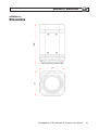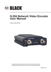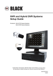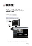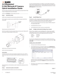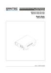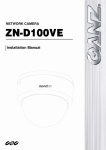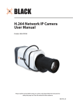
1
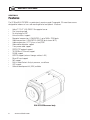
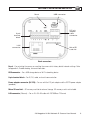
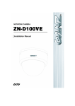
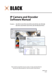
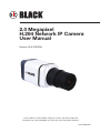
® 2.0 Megapixel H.264 Network IP Camera User Manual Product: BLK-IPS102M Please read this manual before using your camera, and always follow the instructions for safety and proper use. Save this manual for future reference. BLK-IPS102M_CM WARNING RISK OF ELECTRIC SHOCK. DO NOT OPEN. To reduce the risk of electric shock, do not remove cover (or back). No user serviceable parts inside. Refer servicing to qualified service personnel. CAUTION Operate this camera only in environments where the temperature or humidity is within the recommended range. Operation in extreme temperatures or humidity levels may cause electric shock and shorten the life of the product. LEGAL NOTICE SC Black is a registered trademark of Supercircuits, Inc. Supercircuits products are designed to meet safety and performance standards with the use of specific Supercircuits authorized accessories. Supercircuits disclaims liability associated with the use of nonSupercircuits authorized accessories. The recording, transmission, or broadcast of any person’s voice without their consent or a court order is strictly prohibited by law. Supercircuits makes no representations concerning the legality of certain product applications such as the making, transmission, or recording of video and/or audio signals of others without their knowledge and/or consent. We encourage you to check and comply with all applicable local, state, and federal laws and regulations before engaging in any form of surveillance or any transmission of radio frequencies. Other trademarks and trade names may be used in this document to refer to either the entities claiming the marks and names or their products. Supercircuits, Inc. disclaims any proprietary interest in trademarks and trade names other than its own. No part of this document may be reproduced or distributed in any form or by any means without the express written permission of Supercircuits, Inc. © 2010 Supercircuits, Inc. All rights reserved. 11000 N. Mopac Expressway, Building 300, Austin, TX 78759 Sales/Support: 1.800.335.9777 | Fax: 1.866.267.9777 ii www.sc-black.com Table of Contents SECTION 1 Features. . . . . . . . . . . . . . . . . . . . . . . . . . . . . . . . . . . . . . . . . . . . . . . . . . . . . . . . 2 SECTION 2 Installation and Setup . . . . . . . . . . . . . . . . . . . . . . . . . . . . . . . . . . . . . . . . . . . . . 4 2.1 What’s in the box. . . . . . . . . . . . . . . . . . . . . . . . . . . . . . . . . . . . . . . . . . . . . 4 2.2 Tools you need. . . . . . . . . . . . . . . . . . . . . . . . . . . . . . . . . . . . . . . . . . . . . . . 4 2.3 Find an IP address for your camera. . . . . . . . . . . . . . . . . . . . . . . . . . . . . . . 4 2.4 Check LAN for default IP address compatibility. . . . . . . . . . . . . . . . . . . . . . 8 2.5 Install IPAdmin Tool. . . . . . . . . . . . . . . . . . . . . . . . . . . . . . . . . . . . . . . . . . . 9 2.6 Mount the camera. . . . . . . . . . . . . . . . . . . . . . . . . . . . . . . . . . . . . . . . . . . . 9 2.7 Connections. . . . . . . . . . . . . . . . . . . . . . . . . . . . . . . . . . . . . . . . . . . . . . . . 11 2.8 Configure the camera IP address. . . . . . . . . . . . . . . . . . . . . . . . . . . . . . . . 15 2.9 Setup the camera Basic Configuration. . . . . . . . . . . . . . . . . . . . . . . . . . . . 17 2.10Aim, focus, and image quality adjustments. . . . . . . . . . . . . . . . . . . . . . . . 21 2.11Speaker/microphone setup . . . . . . . . . . . . . . . . . . . . . . . . . . . . . . . . . . . . 22 2.12Cleaning. . . . . . . . . . . . . . . . . . . . . . . . . . . . . . . . . . . . . . . . . . . . . . . . . . . 24 SECTION 3 Specifications. . . . . . . . . . . . . . . . . . . . . . . . . . . . . . . . . . . . . . . . . . . . . . . . . . . 25 APPENDIX A Troubleshooting. . . . . . . . . . . . . . . . . . . . . . . . . . . . . . . . . . . . . . . . . . . . . . . . . 28 A.1 Camera reset. . . . . . . . . . . . . . . . . . . . . . . . . . . . . . . . . . . . . . . . . . . . . . . 28 A.2 Set to factory default settings . . . . . . . . . . . . . . . . . . . . . . . . . . . . . . . . . . 28 A.3 Checking your Firmware . . . . . . . . . . . . . . . . . . . . . . . . . . . . . . . . . . . . . . 28 A.4 Support. . . . . . . . . . . . . . . . . . . . . . . . . . . . . . . . . . . . . . . . . . . . . . . . . . . 29 APPENDIX B Power over Ethernet. . . . . . . . . . . . . . . . . . . . . . . . . . . . . . . . . . . . . . . . . . . . . . 30 B.1 PoE compatibility. . . . . . . . . . . . . . . . . . . . . . . . . . . . . . . . . . . . . . . . . . . . 30 B.2 Power classification. . . . . . . . . . . . . . . . . . . . . . . . . . . . . . . . . . . . . . . . . . 30 APPENDIX C Dimensions. . . . . . . . . . . . . . . . . . . . . . . . . . . . . . . . . . . . . . . . . . . . . . . . . . . . 31 2.0 Megapixel H.264 Network IP Camera User Manual 1 SECTION 1: FEATURES SECTION 1 Features The SC Black BLK-IPS102M is a professional, premium-grade 2 megapixel, CS-mount box camera designed for indoor use. Lens and mounting bracket are optional. It features: • • • • • • • • • • • • • • • • • • Aptina™ 1/3.2” (4:3) CMOS 2.0 megapixel sensor Dual streaming mode De-interlacing on DSP Unicast/multicast support Megapixel compression: H.264/MPEG-4, up to 1600 x 1200 pixels Video compression: H.264/MPEG-4/MJPEG (dual stream @ D1) Audio compression: G.711 (µLaw, aLaw)/PCM Video motion detection support 2-way mono audio support RTSP/HTTP protocol support 10/100 Base-T Ethernet support RS485 support USB 2.0 support (external storage, wireless LAN) Micro SD card support PoE support Built-in video Content Analysis presence, surveillance OSD support Software development kit (SDK) available BLK-IPS102M camera body 2 www.sc-black.com SECTION 2: INSTALLATION AND SETUP Reset USB connector DC jack adapter cable connector 9-pin terminal block LAN connector Micro SD card slot Back connectors Reset – For restarting the camera, or resetting the camera to its factory default network settings. Refer to Appendix A, Troubleshooting, for more information. USB connector – For a USB storage device or Wi-Fi networking device 9-pin terminal block – For DI, DO, audio, and serial communication Power adaptor connector (DC 12V) – For use with the DC jack adapter and the DC12V power adapter (provided). Micro SD card slot – SD memory card slot for external storage. SD memory card is not included. LAN connector (Ethernet) – For an RJ-45 LAN cable with 10/100Base-T Ethernet 2.0 Megapixel H.264 Network IP Camera User Manual 3 SECTION 2: INSTALLATION AND SETUP SECTION 2 Installation and Setup 2.1 What’s in the box Your camera includes the following: • • • • • • • • • BLK-IPS102M camera Cap for protecting the sensor DC power adapter with power plugs for different powering sources DC jack adapter cable Adapter for mounting the camera 9-pin terminal block Hex wrench Quick installation guide CD mini disk with application software, software manual, and camera manual (this document) 2.2 Tools you need To install the camera, you will need: • • • • Phillips #1 or #0 screwdriver Mounting bracket Compatible lens PC with Microsoft® Windows® XP SP3 or newer NOTE Supercircuits recommends that a manual iris megapixel lens is used with this camera to support its full resolution. 2.3 Find an IP address for your camera Devices attached to an Local Area Network (LAN) are each assigned a unique address (IP address) that they use when sending messages with each other. No two devices on a single Ethernet network can have the same IP address. Otherwise, conflicts will occur. 4 www.sc-black.com SECTION 2: INSTALLATION AND SETUP Your IP camera is pre-configured with a static IP address, subnet mask, and gateway setting: IP address: 192.168.0.100 Subnet mask: 255.255.255.0 Gateway: 192.168.0.1 Usually these settings are changed during installation to ones more compliant with the network configuration. When initially connecting a camera to your network, there is a possibility that the camera’s preconfigured IP address may already be in use on the network. Check your network before attaching your camera to ensure there is not a conflict with another device. Also, install and reconfigure additional cameras one at a time to avoid conflicts with other cameras or devices. Use the following procedure to determine a compliant IP address to assign to your camera. If connecting your camera to a large enterprise network, consult with your network administrator before attaching the camera to the LAN for network settings to ensure that your camera won’t initially conflict with other devices. Your network administrator should also setup WAN (Internet) access to the camera. If you encounter a problem and need to contact Supercircuits Support, first complete the chart in step 1 about your Computer (PC) and camera network settings, if possible. Support will need this information to provide assistance. 1. At a PC attached to the same LAN that will be shared with your camera, determine the IP address, subnet mask, and default gateway of your PC and record it in Table 1. To find this information, do the following at the Windows desktop: a. Hold down the Windows key and press r to open the Run dialog box. b. Type cmd in the entry field and click OK to open the DOS command window. 2.0 Megapixel H.264 Network IP Camera User Manual 5 SECTION 2: INSTALLATION AND SETUP c. At the command prompt, enter ipconfig. The PC will display Ethernet data associated with your Ethernet adapter LAN connection. d. Enter the IP Address, Subnet Mask, and Default Gateway for your PC’s Ethernet adapter into Table 1. Example: Typical use of ipconfig in Windows XP NOTE The Ethernet adapter data you see by using ipconfig will probably be different from that shown in the example above. If you are using Windows Vista or Windows 7, the IP address is identified as the “IPv4 Address.” Table 1. PC/Camera network settings Computer (PC) Camera IP Address Subnet Mask Default Gateway CAUTION 2. 6 If connecting your camera to an enterprise network, consult with your network administrator for the camera IP address, subnet mask, and default gateway. At your PC, find an IP address on your network that is not in use: www.sc-black.com SECTION 2: INSTALLATION AND SETUP a. Write down the EXACT IP address of your PC up to the third/last period. Using the example shown above, this expression is: 192.168.1. b. After the third period, include any number between 1 and 256 that is different from the one in your PC’s IP address, 168. As a first try, let’s choose 200, which will form the IP address 192.168.1.200. c. Next, use the ping command in the DOS window to see if this IP address is in use on your network. The format of the ping command is: ping <IP address> To test this IP address, enter ping 192.168.1.200. Any reply received from the ping indicates that a device on the network is already using this IP address and you can connect to it. In the example shown above, the message “Reply from 192.168.1.200: ..” indicates that your PC can reach the device with that IP address, and that address is in use. d. Since the ping test of the IP address we tried showed the address was in use, try another number between 1 and 256. For example, let’s ping 192.168.1.201. At the DOS prompt, enter: ping 192.168.1.201 2.0 Megapixel H.264 Network IP Camera User Manual 7 SECTION 2: INSTALLATION AND SETUP e. In this test, the message “Request timed out” indicates that your PC cannot reach the device with that IP address, and that address is probably not in use. Enter this number into Table 1. If this test indicated that that this IP address is in use, try other IP address using the steps above until an unused address is found. 2.4 Check LAN for default IP address compatibility Because all SC Black cameras and encoders are factory configured with the static IP address 192.168.0.100, check the LAN before connecting your camera to ensure that network conflicts won’t occur. At a Microsoft Windows computer attached to the LAN subnet where the camera will be connected, open a Command Prompt window and enter: ping 192.168.0.100 The “Request timed out” response indicates that the IP address is not in use and the camera can be connected without causing errors. 8 www.sc-black.com SECTION 2: INSTALLATION AND SETUP 2.5 Install IPAdmin Tool The IPAdmin Tool, included on the CD mini disk, will discover cameras installed on your network and enable you to perform the initial network setup for each camera. After a camera is setup on the network, the Microsoft Internet Explorer (IE) web browser can be used to see video from the camera, set the camera’s password, date and time, finalize camera hardware adjustments, and configure the camera for functional requirements. The IPAdmin Tool can be loaded on a Microsoft Windows XP, Vista or Windows 7 operating system. To use this utility for the initial setup of your camera, your computer must be connected to the same network subnet as your camera. To install the IPAdmin Tool, do the following: 1. Insert the CD mini disk provided with your camera into your computer’s CD ROM drive and open the CD in a Windows Explorer window. 2. Establish a directory on your computer hard drive for the IPAdmin Tool application. 3. Copy the files IPAdminTool.exe and IPAdminTool.dll to your new directory. 2.6 Mount the camera 1. Install the camera mounting bracket using the instructions provided with the bracket. 2. Determine where the camera will be mounted and record the Media Access Control (MAC) address of the camera. The MAC address can be found on the label on the bottom of the camera. Record the information in the following table. Location: MAC address: 3. Attach the adapter for mounting the camera to the side with the label or to the opposite side with the screws provided. 2.0 Megapixel H.264 Network IP Camera User Manual 9 SECTION 2: INSTALLATION AND SETUP Mounting adapter 4. Remove the protective cap covering the camera CCD. 5. Attach the lens assembly to the camera by screwing it clockwise onto the camera until it is fully seated. The lens may require a mounting ring adapter to fit onto the camera. Loosen the set screw if necessary. Mounting ring 6. 10 Tighten the lens set screw with the hex wrench provided. www.sc-black.com SECTION 2: INSTALLATION AND SETUP 7. Attach the camera to the mounting bracket. Use the instructions provided with the bracket. 2.7 Connections Connections to the camera for audio in and out (microphone and speaker), DI sensor, DO alarm, and RS‑485 control are made through the 9-pin terminal block. 9-pin terminal block Terminal block pin assignments If the 9-pin terminal block is detached from the camera, plug it into the mating connector on the back of the camera. 2.7.1 Audio in/out connections The camera includes an interface for a mono audio input (from a microphone) and a mono audio output (to a speaker). The audio output is a low level signal that requires an amplified speaker (see Specifications). The configuration of the audio wiring (Aout, Ain) is shown in the following diagram. 2.0 Megapixel H.264 Network IP Camera User Manual 11 SECTION 2: INSTALLATION AND SETUP Audio in/out wiring schematic To connect a speaker and/or microphone to the camera: 1. Strip 1/4” of insulation from the microphone and speaker wires and insert them into the terminal block in the pin locations shown in the terminal block figure above. Note that the common (ground) leads of the microphone and speaker share the same terminal block pin. CAUTION Do not attach a headphone or earphone directly to the camera. 2.7.2 Sensor in (DI) connection The camera provides one channel for sensor input that can be connected to either a voltage type or relay type sensor. For voltage type sensors, the camera allows an input voltage range of 0 ~ 24 V DC, with a 1 V DC threshold (see Specifications). The configuration of the sensor input wiring is illustrated in the following schematics. CAUTION 12 Do not exceed the maximum input voltage or the relay switching rate. Refer to the specifications in this manual for more information. www.sc-black.com SECTION 2: INSTALLATION AND SETUP Voltage type sensor wiring schematic Relay type sensor wiring schematic To connect a sensor to the camera, strip 1/4” of insulation from the sensor wires and insert them into the terminal block in the DI 1 and C pin locations shown above. The pin marked C in the terminal block is the common (COM) pin. 2.7.3 Alarm out (DO) connection The camera supports one alarm out connection to relay type device. It provides up to 24 VAC @ 500 mA or 12 V DC @ 1 A. The configuration of the relay type alarm wiring is illustrated in the diagram below. CAUTION Do not exceed the maximum relay rating. Refer to the specifications in this manual for more information. 2.0 Megapixel H.264 Network IP Camera User Manual 13 SECTION 2: INSTALLATION AND SETUP Relay type alarm wiring schematic To connect an alarm reporting device to the camera, strip 1/4” of insulation from the alarm wires and insert them into the terminal block in the DO 1 and C pin locations shown above. The pin marked C on the terminal block is the common (COM) pin. 2.7.4 RS-485 device connection The camera provides one RS-485 interface connection. The wiring signal polarity to the connector block is shown in the schematic below. RS-485 device wiring schematic To connect an RS-485 device wiring to the camera, strip 1/4” of insulation from the wires and insert them into the terminal block in the RS-485 pin locations shown above. Observe the signal polarity shown in the schematic. 2.7.5 LAN and power connection Your camera can be powered locally with a 12 V DC adapter, or across the LAN (PoE, see Appendix B). If using PoE powering, you do not need to attach a power adapter to the camera. 14 www.sc-black.com SECTION 2: INSTALLATION AND SETUP 1. Attach a LAN cable to the Ethernet connector on the back of the camera. 2. Attach the DC jack adapter cable to the DC 12V power adapter terminals on the back of the camera. Connect the red wire of the adapter cable to the + terminal, and the black (or white) wire to the - terminal. DC jack adapter cable 3. Attach the DC jack Adapter to the DC power adapter provided, and plug the adapter into a power source. 2.8 Configure the camera IP address 1. Open the directory where you installed IPAdmin Tool. Double click the file IPAdminTool.exe to start the application. When the IPAdmin Tool starts, it will discover all of the IP cameras it supports that exist on the network. The discovery process may take a few minutes. 2.0 Megapixel H.264 Network IP Camera User Manual 15 SECTION 2: INSTALLATION AND SETUP IPAdmin Tool discovering 192.168.0.100 2. In the Product list, find the entry with the same MAC address as the camera you installed. If the camera is not shown, click Refresh repeatedly to update the list. 3. Right click on the entry for your camera and select IP Address. 4. In the IP Setup window: 16 a. Select the Static option if it is not selected. This option is required for if camera video will be recorded by a network DVR, or if you want to view video from the camera across a WAN (Internet). b. Enter the IP address for your camera from Table 1 into the IP Address field. c. Enter the subnet mask for your computer from Table 1 into the Subnet Mask field. d. Click SETUP. A Login window will open. www.sc-black.com SECTION 2: INSTALLATION AND SETUP IP Setup window 5. In the Login window, enter the ID and PW (password) for your camera and click Login. The default administrator values for the ID and PW are root and pass. After entering ID and PW, the IP Setup window closes. 6. In the IPAdmin Tool window, click Refresh and verify that the entry representing the camera now shows the new IP address. 2.9 Setup the camera Basic Configuration In this procedure, Microsoft Internet Explorer (IE) browser is used to setup the camera administrator and user passwords, date, and time. 1. Open the IE browser. 2. In the URL field (Internet address), enter the IP address for your camera in the format: http://<IP address>/ where <IP address> is the IP address of your camera. Following the example earlier in this guide, the entry would be: http://192.168.1.201 3. If prompted to install an ActiveX control such as AxNVC.cab, follow screen prompts to install the software. 2.0 Megapixel H.264 Network IP Camera User Manual 17 SECTION 2: INSTALLATION AND SETUP IE prompt to install ActiveX control Typical initial camera view NOTE 4. 18 If, after logging into your camera, you cannot see live video and the message: “Can not Create XMLDOMDocument Install MSXML4.0” appears, download and install the MS XML 4.0 library. This library can be found at: http://www.microsoft.com/downloads/details.aspx?familyid=3144B72B-B4F2-46DAB4B6-C5D7485F2B42&displaylang=en In the camera window, click the SETUP link in the upper right corner of the window. Enter the User name and Password for the camera, and click OK. The default administrator values are root and pass. The Basic Configuration window will open. www.sc-black.com SECTION 2: INSTALLATION AND SETUP 5. Under the Basic Configuration menu, click Date & Time. In the Date & Time Setting options: a. Select the Time Zone you prefer. b. Select the synchronization method, or Set Manually bullet and enter the appropriate information. c. Select the Sync Source and Interval you prefer. d. Click Apply. 2.0 Megapixel H.264 Network IP Camera User Manual 19 SECTION 2: INSTALLATION AND SETUP 6. In the Basic Configuration menu, click Users. 7. In the User List, click root, and then click Modify and follow the prompts. Setup the root user with a new password and click OK. 20 www.sc-black.com SECTION 2: INSTALLATION AND SETUP 8. In the Users menu, click Apply, then click OK to restart the webserver (if you wish to do so at this time). 9. Click Add to include other administrators, operators or viewers to the user list. Follow the screen prompts to complete the entries. 10. Click VIEW in the upper right corner of the window to return to the camera live view. 2.10 Aim, focus, and image quality adjustments Use the documentation provided with your camera mounting bracket and lens to aim the camera at your security target and, depending on the attached lens, set focus and zoom, while observing the video image from the camera. Adjustments to the image brightness, contrast, hue, saturation, and sharpness are performed through the web browser: 1. From the View window, click: SETUP > Video & Audio > Video-In 2.0 Megapixel H.264 Network IP Camera User Manual 21 SECTION 2: INSTALLATION AND SETUP 2. Scroll to the bottom of the screen and click the PREVIEW button. Follow the screen instructions to open the camera view in another IE window. 3. While observing the video in the PREVIEW window, adjust the values for brightness, contrast, hue, saturation, sharpness, and/or other parameters on screen. Click Apply to see the effect of the change. Make any necessary adjustments to produce the best video image. 4. Close the PREVIEW window and click VIEW to return to the normal viewing window. 2.11 Speaker/microphone setup Verify the functionality of the speaker and microphone setup at the camera, and adjust volume levels. 1. 22 On the VIEW screen, click SETUP > Video & Audio > Audio to open the Bi-directional Audio Settings menu. www.sc-black.com SECTION 2: INSTALLATION AND SETUP 2. In the Bi-directional Audio Settings menu, click the checkboxes to select “Listen to the audio from server with setting below” and “Talk to the speakers of server”. 3. Click Apply, and then click VIEW to return to the camera view screen. 4. On the VIEW screen, check the SPK and MIC options to enable the speaker at the camera and the microphone on your computer. 5. At your computer, listen for sounds from the microphone at the camera. If necessary, adjust the volume from the camera. Click: SETUP > Video & Audio > Audio to re-open the Bi-directional Audio Settings menu. In the Listen frame, adjust the volume to the preferred level. Click Apply. 6. Use a microphone at your PC to send audio to the camera speakers. Verify that your microphone audio is heard at the speaker. To adjust the speaker volume go to the Bi-directional Audio Settings menu. In the Talk to frame, adjust the volume to the preferred level. Click Apply. 2.0 Megapixel H.264 Network IP Camera User Manual 23 SECTION 2: INSTALLATION AND SETUP 2.12 Cleaning Clean the camera housing with an approved glass cleaning solution and a lint free cloth. • • Dust can be removed from the unit by wiping it with a soft damp cloth. To remove stains, gently rub the surface with a soft cloth moistened with a mild detergent solution, then rinse and dry it with a soft cloth. Remove all foreign particles, such as plastic or rubber materials, attached to the camera housing. These may cause damage to the surface over time. CAUTION 24 Do not use benzene, thinner or other chemical products on the camera assembly; these may dissolve the paint and promote damage of the surfaces. Before using any chemical product, read the accompanying instructions carefully. www.sc-black.com SECTION 3: SPECIFICATIONS SECTION 3 Specifications Table 2.Specifications Camera Module Image Sensor Aptina (Micron®) 1/3.2” (4:3) CMOS 2M Effective Pixels 1600 x 1200 (UXGA, 2M) Scanning system Progressive scan Dynamic Range 71 dB SNR Max 42.3 dB Minimum Illumination 0.5 Lux (50 IRE), 0.1 Lux (DSS x5 ON) Lens (Optional) CS mount Day & Night S/W Video Megapixel Compression H.264 and MJPEG Compression Format H.264, MPEG-4, and MJPEG Number of Streams Dual Stream, Configurable Resolution See Resolutions table below Compression FPS (If VCA or Burnt-in Annotation is on, fps could be less.) H.264 5 fps @ UXGA (1600 x 1200), 8 fps @ SXGA (1280 x 1024), 12 fps @ HD720 (1280 x 720), 15 fps @ XGA (1024 x 768), D1 (720 x 480) MJPEG 15 fps @ UXGA (1600 x 1200) MPEG4 15 fps @ D1 (720 x 480) Motion detection Support (DSP) Burnt-in text Support (DSP) Video output Not available Audio Input/output 1/1 channel Compression format G.711 Function Digital input 1 channel (dry and wet contact selectable) Digital output 1 channel (dry contact) RS-485 Support RS-232 Not available Network 10/100Base-T 2.0 Megapixel H.264 Network IP Camera User Manual 25 SECTION 3: SPECIFICATIONS Protocol TCP/IP, UDP/IP, HTTP, RTSP, RTCP, RTP/UDP, RTP/TCP, SNTP, mDNS, UPnP, SMTP, SOCK, IGMP, DHCP, FTP, DDNS, SSL v2/v3, IEEE 802.1X, SSH USB 2.0 Support (Mini-B plug) SD slot Supported (microSD type, not included) Electrical Characteristics Audio input Line-in, 1.43 Vp-p (min 1.35 Vp-p, max 1.49 Vp-p), 39 KΩ Audio output Line-out, 46 mW Power, 16 Ω Sensor (D/I) TTL level 4.5 V threshold, max 50 mA Alarm (D/O) Max 500 mA @ 24 V AC or 1A @ 12 V DC Power source (approx.) 12 V DC (screw terminal) Power over Ethernet (PoE) 300 mA @ +12 V Power consumption (approx.) 300 mA @ +12 V Mechanical characteristics Material Aluminum (die-casting) Color White pearl Dimensions 2.17” (W) x 2.17” (H) x 3.60” (L) Weight 0.57 lbs (approx.) Environmental Conditions Operating Temperature (32˚F ~ 122˚F (0˚C ~ 50˚C) Operating Humidity Up to 85% RH (Non-condensing) Table 3.Resolutions per codec frame rate Resolution MPEG4 H.264 UXGA (1600 x 1200) Not available 5 fps SXGA (1280 x 1024) Not available 8 fps HD720 (1280 x 720) Not available 12 fps XGA (1024 x 768) Not available D1 (720 x 486) 15 fps 4CIF (704 x 576) VGA (640 x 480) CIF (352 x 288) 15 fps QVGA (320 x 240) QCIF (176 x 144) 26 MJPEG www.sc-black.com 15 fps SECTION 3: SPECIFICATIONS Table 4.Video Content Analysis (optional) VCA Presence High Performance Advanced tracking algorithm, low false alarm rate Easy to Use Intuitive web browser interface Detection Zones Multi-segment polygons and lines On-screen Display Real-time display of tracking data and events Burnt-in Annotation Stream VCA Surveillance Detection Behavior Camera tampering, direction, stopping, loitering, entering, exiting, appear, and disappear filters 3D Behavior Perspective corrected size and speed filters Statistics Counting functions and other statistics Meta Data Binary XML format Image Stabilization Electronic Stabilization Removes camera sway 2.0 Megapixel H.264 Network IP Camera User Manual 27 APPENDIX A: TROUBLESHOOTING APPENDIX A Troubleshooting A.1 Camera reset To reset the camera while it is in use: 1. Press and hold the Reset button for 3 seconds. 2. Wait for the camera to reboot. A.2 Set to factory default settings The camera network settings can be forced to the initial (factory default) settings: • • • • • IP address – reset to 192.168.0.1 Subnet mask – reset to 255.255.0.0 Gateway – reset to 192.168.0.1 User ID – reset to root Password – reset to pass To force the camera to the factory settings: 1. Disconnect the power (adapter) from the device. 2. While pressing and holding down the Reset button, connect the power to the camera. 3. Release the Reset button 5 seconds after powering on the camera. 4. Wait for the camera to reboot. A.3 Checking your Firmware Firmware is software embedded in the camera that determines many of its features and functionality. The current firmware version number in your camera can be found by viewing video from the camera in IE, and then clicking SETUP > About > Version. Contact Supercircuits Support for up to date firmware. 28 www.sc-black.com APPENDIX A: TROUBLESHOOTING A.4 Support If you cannot resolve an issue, please contact Supercircuits Support at 1.800.335.9777 for assistance. When you contact support, please provide the server reports, log file and a brief description of the problem, if possible. • To generate a server reports, enter the following into the IE address field: https://<IP ADDRESS>/nvc-cgi/admin/param.cgi?action=list - and https://<IP ADDRESS>/nvc-cgi/admin/vca.cgi?action=list where <IP ADDRESS> is the IP address of your camera. The server report contains important information about the device, as well as a list of the current parameters. • To generate a log report, use IE to log into the unit. In the View screen, click the following items, entering security information when required: SETUP > Maintenance > System Log > LOG LIST Click the name of the Log List of interest to open it. 2.0 Megapixel H.264 Network IP Camera User Manual 29 APPENDIX B: POWER OVER ETHERNET APPENDIX B Power over Ethernet The BLK-IPS101 camera supports Power over Ethernet (PoE) in conformance with the IEEE 802.3af standard. IEEE 802.3af allows for two power options for Category 5 cables. The PoE module signature and control circuit provides the PoE compatibility signature and power classification required by the Power Sourcing Equipment (PSE) before applying up to 15 W power to the port. The high efficiency AC/DC converter operates over a wide input voltage range and provides a regulated low ripple and low noise output. The AC/DC converter also has built-in overload and short-circuit output protection. • • B.1 PoE compatibility With non Power Sourcing Equipment (PSE) When it is connected with non PSE, use the power adaptor to provide power to the camera. With power adaptor Connecting both PSE and power adaptor does not do any harm to the products. Disconnecting power adaptor while it is operating does not stop operation. The product continues to work without rebooting. B.2 Power classification The PoE Power Class supported by the IP device is Class 0. Class Usage Minimum Power Levels Output at the PSE Maximum Power Levels at the Powered Device 0 Default 15.4 W 0.44 to 12.95 W 30 www.sc-black.com APPENDIX C: DIMENSIONS APPENDIX C Dimensions 2.0 Megapixel H.264 Network IP Camera User Manual 31 32 www.sc-black.com