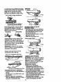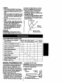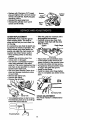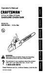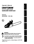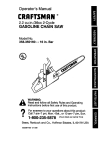
1
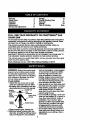
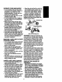
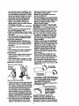
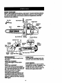
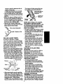
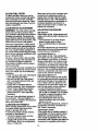
Operator's Manual
CRAFTSMAN
2.6 cu. in./42cc 2-Cycle
GASOLINE CHAIN SAW
Model No.
358.351380 - 18 In. Bar
358.350180 - 18 In. Bar
@
Read and follow all Safety Rules and Operating
WARNING:.:
Instructions before first use of this product.
For answers
to your
questions
thispm,
product:
Call
7 am-7 pm,
Mon.-Sat.,
or about
10 am-7
Sun.
•
1-800-235-5878
(Hours listed are CentraITIme)
Sears, Roebuck and Co., Hoffman Estates, IL 60179 USA
_ _=_.._r_
530087615 06/08/98
Warranty
Safety Rules
Assembly
Operation
Maintenance
Service and Adjustments
2
2
5
6
11
14
Storage
,
Trouble ShootingChart
Parts List
Spanish
Pads & Ordering
16
17
20
24
Back
FULL ONE YEAR WARRANTY ON CRAFTSMAN ® GAS
CHAIN SAW
For one year from the date of purchase, when this Craftsman Gas Chain Saw is
maintained, lubricated and tuned up according to the operator's manual, Sears
will repair, free of charge, any defect in material or workmanship.
This warranty excludes the bar, chain, spark plug and air filter,which are
expendable parts and become wom during normal use.
If this Chain Saw is used for commercial purposes,this warranty applies for only
90 days from the date of purchase. If this Chain Saw is used for rental purposes,
this warranty applies for only 30 days from the date of purchase.
WARRANTY SERVICE IS AVAILABLE BY RETURNING THIS CHAIN SAW TO
THE NEAREST SEARS SERVICE CENTER IN THE UNITED STATES.
This warranty gives you specific legal rights,and you may also have other rights
which vary from state to state,
/
Sears, Roebuck and Co., D/817 WA, Hoffman Estat"es,]L 60179
WARNING: Always disconnect spark
such as non-fogging, vented goggles
or face screen; an approved safety
plugwire when making repairs except
hard hat; and sound barriers (ear
for carburetor adjustments. Because a
plugs or mufflers) to protect your
chain saw is a high-speed woodcutting
hearing° Regular users should have
tool, careless or improper use of this
hearing checked regularly as chain
tool can cause serious injury.
saw noise can damage hearing. SePLAN AHEAD
cure hair above shoulder length.
• Restrictthe use of your saw to adult
• Keep all parts of your body away from
users who understandand can follow
the chain when the engine is running.
-- --thesafety rules, precautions,and oper•
Keep children, bystanders, and aniating instructionsfound in thb manual.
mals at least 30 feet (10 meters)
Hearing
_=.la
SafetyHat
away from the work area when startProtection_ __
Eye
ing and using the saw.
Snug
I I,_r-,_Protection
• Do not handle or operate a chain saw
when you are fatigued, ill, or upset, or
Clothing
_
_/Gloves
if you have taken alcohol, drugs, or
medication. You must be in good
physloai condition and mentally alert.
If you have any condition that might
j
Safety Chaps
be aggravated by strenuous work,
check with doctor before operating.
al=llMl_
• Do not start cuffing until you have a
• Wear protective gear. Always use
clear work area, secure footing, and
" ---_smel-toed safety footwear with nonespecially if you are felling a tree, a
slipsoles; snug-fitting clothing; heavyretreat path.
Rtting "---.._ ,_
Heavy Duty
duty, non-slip gloves; eye protection
OPERATE YOUR SAW SAFELY
• Do not operate with one hand. Serious injuryto the operator, helpers, or
bystanders may resultfrom onehanded operation. A chain saw is intended for two-handed use.
• Operate the chain saw only in a_wellventilated outdoor ar#-a.
• Do not operate saw from a ladder or
in a tree, unless you are specifically
trained to do so.
• Make sure the chain will not make
contact with any object while starting
the engine. Never try to start the saw
when the guide bar is in a cut.
• Do not put pressure on the saw, especially at the end of the cut. Doing
so can cause you to lose control
when the cut is completed.
• Stop engine before setting saw down.
• Hand carry saw only when engine is
stopped. Carry with muffler away from
body; guide bar & chain projecting behind you; guide bar preferably covered with a scabbard.
MAINTAIN
YOUR
SAW IN GOOD
WORKING
ORDER
• Have all chain saw service performed
by a qualified service dealer except
the items listed in the maintenance
section of this manual.
• Make certain the saw chain stops
moving when the throttle trigger is released. For correction, refer to "Carburetor Adjustments."
• Keep the handles dry, clean, and free
from oil or fuel mixture.
• Keep caps and fasteners securely
tightened.
• Use only Craftsman accsssories and
replacement parts as recommended.
Never modify your saw.
HANDLE
FUEL
WITH
CAUTION
• Do not smoke while ha-ndlihg fuel or
while operating the saw.
• Eliminate all sources of spmks or flame
in aress where fuel is mixed or poured.
• Mix and pour fuel in an outdoor area
and use an approved, marked container for all fuel purposes. Wipe up
all fuel spills before starting saw.
• Move at least 10 feet (3 meters) from
fueling site before starting.
•Tum the engine off and let saw cool in
a non=combustible area, not on dry
leauas;-straw, paper, etc. Slowly remove fuel cap and refuel unit.
• Store the unit and fuel in a cool, dry
well ventilated space where fuel vapors cannot reach sparks or open
flames from water heaters, aiectric
motors or switches,furnaces, etc.
GUARD AGAINST KICKBACK
Follow all safety rules to help avoid
kickbackand other forces which can
result in serious injury.
%
_
Kickback Path
Avoid Obstructions
Clear The Working Area
WARNING:
Rotational Kickback can
occur when the moving chain contacts
an object at the upper portion of the tip
of the guide bar. Contact at the upper
portion of the, tip of the guide bar can
cause the chain to dig into the object,
which stops the chain for an instant. The
result is a lightning fast, reverse reaction
which kicks the guide bar up and back
toward the operator.
Pinch-Kickback and Pull-In occur when
the chain is suddenly stopped by being
pinched, caught, or by contacting a foreign object in the wood. This sudden
stopping of the chain results in a reversal of the chain force used to cut wood
and causes the saw to move in the opposite direction of the chain rotation.
Pinch-Kickback drives the saw straight
back toward the operator. Pull-In pulls
the saw away from the operator.
REDUCE
THE
KICKBACK
CHANCE
OF
• Recognize that Idctd0a_ can h..appen..
W'_ a basic understanding of kickback,
you can reduce the element of suqxise
which contributes to accidents.
• Never let the moving chain contact
• any object at the tip of the guide bar.
Keep working area free from obstructions such as other trees, branches,
rocks, fences, stumps, etc. Eliminate
or avoid any obstruction that your saw
° chain could hit while cutting.
Keep saw chain sharp and propedy
tensioned. A loose or dull chain can
increase the chance of kickback. Follow manufacturer's chain sharpening
and maintenance instructions.Check
tension at regular intervals, but never
with engine running. Make sure bar
clamp nuts are securely tightened.
speed. If the chain is moving at a
slower speed, there is greater chance
i ofegin
and contin._,
cuttin9 at full
kickback
occurring.
Use extreme caution when reentering
a cut.
the
bar Iplunge
cuts). with the
i tip
Do of
not
attempt
cuts starting
Watch for shifting logs or other forces
that could close a cot and pinch or fall
into chain.
• Use the specified Reduced-Kickback
Guide Bar and Low-Kickback Chain.
Avoid Pinch-Kickback:
• Be extremely aware of situations or
obstructions that can cause matedai
to pinch the top of or otherwise stop
the chain.
• Do not cut more than one log at a
time.
• Do not twist saw as bar is withdrawn
from an undercut when bucking.
Avoid Pull-In:
at ful/speed and the saw housing
i against
lways begin
wood.cutting with the engine
Use wedges made of plastic or wood.
Never use metal to hold the cut open.
MAINTAIN CONTROL
keep y.our body from being in a direct
I,ne with.the cutting chain.
• Stand with your weight evenly balanced onboth feet.
• Do not overreach. You could be drawn
or thrown off balance and lose control.
• Do not cut above shoulder height. It is
difficultto maintain control of saw
above shoulder height.
KICKBACK SAFETY FEATURES
WARNING: The following features are
includedon your saw to help reduce
hazard of kickback; however, such featurse will not totally eliminate this danger. Do not rely only on safety devices.
• Handguard: designed to reduce the
chance of your left hand contacting
the chain if your hand slips off the
front handlebar.
• Position of front and rear handlebars:
designed with distance between handles and "in-line" with each other. The
spreed and =in-line" position of the
hands provided by this design work
together to give balance and res,stance in controlling the pivot of the
saw back toward the operator if kickback occurs,.
• Reduced-Kickback Guide Bar: designed with a Small radius tip which
reduces the size of the kickback dandgerzone. This type bar has been
emonstrated to significantly reduce
the number and seriousness of kickbacks when tested in accordance with
ANSI B175.1.
Stand to the leftof the saw
Small Radius
Tip Guide Bar
of handleb_,
Thumb on
undemid_
" -_
Elbow
locked
Never reverse hand _3os_ons
• A good, firm grip on the saw with both
hands will help you maintain control.
Don't let go. Grip the rear handle with
your right hand whether you are right
or left handed. Wrap the fingers of
your left hand over and around the
front handlebar, and your left thumb
under the front handlebar. Keep your
left arm straight with the elbow locked.
• Position your left hand on the front
handlebar so it is in a straight line with
•":ty_ur right hand on the rear handle
when making bucking cuts. Stand
slightly to the left side of the saw to
• Low-KickbackChain: has met kickback
performance requirementswhen tested
on a representativesample of chain
saws below 3.8 cubicinch
displacementspecifiedin ANSI B175.1.
Low-KickbackChain
Contoured Depth Gauge
_.=p......
Deflects K]ckbock
Force And Allows
Wood
To Gmduafly
longatedGuard
Unk
Ride IntoCutter
SAFETY NOTICE: Exposure to
vibrations through prolonged use of
gasoline powered hand tools could
cause blood vessel or nerve damage in
the fingers, hands, and joints of people
4
_bmneto circulation disorders or
normal swelling. Prolonged use in
cold weather has been linked to blood
vessel damage in otherwise healthy
people. If symptoms occur such as
numbness, pain, loss of strength,
change in skin color or texture, or loss
of feeling in the fingers,dlands, orjoints
d scont nue the use of this tool and
seek medical attention. An
anti-vibrationsystem does not
guarantee the avoidance of these
problems. Users who operate power
tools on a continual and regular basis
must closely monitor their physical
condition and the condition of this to01.
CHAIN BRAKE If this saw is to be used
for commercial logging, you must order
and install a chain brake to comply with
Federal OSHA Regulations for Commemial Logging. Contact your Sears
Service Center or call 1-800-235-5878.
SPARK ARRESTOR: Your sew is
equipped with a temperature limiting
muffler and spark arresting screen
which meets the requirements of
Califomia Codas 4442 and 4443. All
U.S. forest land and the states of
California, Idaho, Maine, Minnesota,
New Jersey, Oregon, and Washington
require by law that many intemal
combustionengines be equipped with a
spark arrestor screen. If you operate a
chain saw in a state or locale where
such regulationsexist, you are legally
responsiblefor maintainingthe
operating conditionof these parts.
Failure to do so is a violation of the law.
Refer to Customer Responsibilities
chart in the MAINTENANCESection.
STANDARDS: This chain saw is listed
by Underwriters Laboratodes, Inc. in
accordance with Amedcan National
Standards for Gasoline-Powered Chain
Saws Safety Requirements (ANSI
B175.1-1991).
CARTON CONTENTS
Check carton contents against the following list.
Model 358.351380 & 358.350180
• Chain Saw (fully assembled)
• Bar tool
• Gloves
• Gas Can
• Bar & Chain Lube
• 2-cycle engine oil
• Examine p_rts for damage. Do not
use damaged parts.
• Ifyou need assistance or find that
parts are missing or damaged, please
call 1-800-235-5878.
NOTE: It is normal to hear the fuel filter
rattle in an empty fuel tank.
Your unit has been factory tested and
the carburetor precisely adjusted_As a
resultyou may smell gasoline or find a
drop of oil/fuel residue on the muffler
when you unpack the unit.
ASSEMBLY
Your saw is fully assembled; no
assembly is necessary.
Model 358.350180 Only
• Chain
• Carrying Case
5
KNOW YOUR SAW
READTHIS OPERATOR'SMANUALAND SAFETYRULESBEFORE OPERATINQ YOUR CHAIN SAW. Compare the illustrationswith your unitto lemilledze
yourself with the Ioc._on of the various controlsand adjustments, save this
manual for future reverence.
Cylinder Cover
Throttle
Lookout
Adjusting
Screw
Rear
Handle
Throttle
Tdgger
Chain
Direction
of Travel
Choke
Knob Bar Clamp Chain Bar Clamp Nuts Guide Bar
Catoher
ON/STOP 8WITCH
The ON/STOP Switch Is used to stop
thee-nglue.
THROTTLE TRIGGER
The throttle trigger controls engine
speed.
THROI"FLE LOCKOUT
The throttle lockout must be pressed.
before you can squeeze the throttle tag-.
ger. This feature prevents you from accidentallysqueezing the rigger.
CHOKE/FAST IDLE LEVER
The choke and fast idle speed am set
by pulhngthe choke lever out fully for
cold or for refueled starting. The choke
., prp._ldes.add_onal fuel when starting 8
cola engine.
PRIMER BULB
The Pdmer Bulb circulates fuel to the
carburetor to provide quicker starling.
CHAIN TENSION
It is normal for a new chain to stretch
dudng first 30 minutesof operation. You
should check your chain tension frequently.See Chain Tension under the
Service and Adjustmentssection.
6
BEFORE STARTING ENGINE
lines and carburetorare empty.Use fresh
fuel next season.See STORAGEinstrucWARNING: Be sure to read the fuel
tionsfor additionel information.
handling informationin the safety rules Never use engine or carburetorcleaner
section of this manual before you begin.
products in the fuel tank or permanent
If you do not understand the fuel handamage may occur.
dling information do not attempt to fuel
See the STORAGEsectionfor additional
your unit. Seek help frgm someone that information..
does understand the informationor call
STOPPING YOUR ENGINE
the customer assistance help line at
1-800-235-5878.
• Move On/Stop switch to STOR
• If engine does not stop, pull choke
GUIDE BAR AND CHAIN OIL
knob out fully.
The chain oiler provides continuous luSTARTING YOUR ENGINE
bricaUonto the chain and guide bar. Be
sure to fill the bar oil tank when you fill
COLD ENGINE OR WARM ENGINE
AFTER RUNNING OUT OF FUEL
the fuel tank (Capacity = 6.8 ft. oz.).
* Fuel engine following instructionsunFor maximum guide bar and chain life,
der FUELING ENGINE.
we recommend you use Craftsman
chain saw bar oil. If Craftsman bar 0il Is * RII bar oil tank with bar oil. Your saw
not available, you may use a good
will use approximately one tank of bar
oll for each tank of fuel mix.
grade SAE 30 oil untilyou are .ableto
obtain Craftsman brand. The oil output
* Move On/Stop switch to ON position.
is automatically metered during opera, Pull choke knob out fully.
tion. Your saw will use approximately
, Prime engine by slowly pressing primer bulb six times.
one tank of bar oil for every tank of fuel
mix. Always fill the bar oil tank when
you fill the fuel tank.
ON/STOP
Switch
FUELING ENGINE
This engine is cedified to operate on
unleaded gasoline. Before operation,
gasoline must be mixed with a good
quality 2-cycle air-cooled engine oil. We
recommend Craftsman brand oil. Mix
gasoline and oil at a ratio of 40:1 (A
40:1 ratio is obtained by mixing 3.2
Primer Bulb
ounces of oil with I gallon of unleaded
• Set saw on the ground. Grip front
gasoline). DO NOT USE automotive oil
handle with your left hand and place
or boat oil. These oils will cause engine
rightfoot through rear handle.
damage. When mixingfuel follow the
instructionsprinted on the container.
Once oil is added to the gasoline,
shake container momentarily to assure
thaf the_uel is thoroughly mixed.
Always read and follow the safety rules
relatingto fuel before f0elir_g your unit.
IMPORTANT
Experienceindicatesthat alcoholblended
fuels (calledgasoholor using ethanolor
methanol)can attractmoisturewhich
leads to separationand formationof
acidsduringstorage. Acidicgas can
damage the fuel system of an engine
whilein storage.
To avoidengine problems,the fuel systam shouldbe emptiedbefore storage for
30 deps'6r longer.Drain the gas tank,
stad the engine and let it run untilthe fuel
Choke knob
NOTE: When pulling the starter rope,
do not use the full extent of the rope.
Do not let stadar rope snap beck.
Hold handle. Let rope rewind slowly.
• Sharply pull starter rope handle 5
times with your righthand. The engine may sound as if it is.trying to
stad before the 5th pull; if so, proceed
to the next step.
7
• Fullypush-inchokeleverand continue to pull starter rope handle until engine starts.
• Then, squeeze and release the
throttle rigger to retum engine to idle
speed.
• Tostopengine,m.qveOn/Stopswitch
to the STOP posit,on.
STARTING A WARM ENGINE
DO NOT use the choke to stad a warm
engine or flooding and hard starting
may occur.
- Move On/Stop switch to ON.
i
•
•
•
Set the chain saw on the ground. Grip
the front handle with your left hand
and
place
your
rightfoot
Slowly
press
primer
bulb through
6 times,the
opening in the rear handle,
Pull choke lever out fully, then push it
In fully to set engine in fast Idle pealton.
Sharp_ pull starter rope handle with
your nght hand until the engine starts,
but no more than 5 times.
Then, squeeze and release the
throttle tdgger to retum engine to idle
speed.
To stop engine, move On/Stop switch
to the STOP position.
DIFFICULT STARTING OR
STARTING A FLOODED ENGINE
The engine may be flooded if it has not
started after 10 pulls. Rooded engines
can be cleared of excess fuel with the
foflowingprocedure:
• Pull choke lever out fully, then push it
in fully to set engine in fast idle peelton.
• Vedfy that the On/Stop switch is in the
ON position.
: With saw on ground, gnp front handle
_ith left hand and place rightfoot
through rear handle.
• Qdp starter rope 6andle and pull rope
firmlv and oui_ldvto start engine. If
not successful, repeat untilengine
starts.
Starling could require many pulls depending on how badly unit is flooded. If
engine still fails to start, refer to TROUBLESHOOTING chad or call
1-800-235-5878.
OPERATING TIPS
• Check chain tension before first use
and after 1 minute of operation. See
Chain Tension in the Maintenance
section.
• Cut wood only. Do not cut metal, plastics, masonry, non-wood building matedals, eta.
• Stop the saw ifthe chain stdkss a foreign object. Inspectthe saw and repair parts as necessary.
• Keep the chain out of dirt and sand.
Even a small amount of did will quickly dull a chain and increase the possi• Practice cuffinga few small logs using
the followingsteps. This will help you
get
the
of using your saw before
bility
of fleer'
kickb..ack.
you begin a major sawing operation.
• Squeeze the throttle tdgger and ollow the engine to reach full speed
before cutting.
• Begin cutting with the saw frame
against the log.
• Keep the engine at full speed the
entire time you are cutting.
• Allow the chainto cut for you. Exert
only light_lownward pressure.
• Release'the:throttle tdgger as soon
as the cut is completed, allowingthe
engine to idle. If you run the saw at
full throttle without a cuffingload,
unnecessary wear can occur.
• To avoid losingcontrol when cut is
complete, do not put pressure on
saw at end of cut.
• Stop engine beforesettingsaw down.
TREE FELUNG TECHNIQUES
WARNING: Check for broken or dead
branches which can fall while cutting
causing sadous injury.Do not cut near
buildingsor electdcal wires if you do not
know the directionof tree fall, nor cut at
night since you will not be able to see
well, nor dudng bad weather such as
rain, snow, or strongwinds, etc.
• Carefully plan your sawing operation
in advance.
• Clear the work area. You need a clear
area all around the tree so you can
have secure footing.
• Study the natural conditionsthat can
cause the tree to fall in a padlcular
direction.These conditions include:
: The
directionand
The wind
lean of
the tree. Thespeed.
lean of a
tree might not be apparent due to
uneven or sloping terrain. Use a
8
plumbor levelto determinethe directionoftree lean.
• Weight and branches on one side.
• Surrounding trees and obstacles.
• Look for decay and rot. If the trunk is
rotted, it can snap and fall toward the
operator.
* Make sure there is enough i'oom=for
the tree to fall. Maintain a distance of
2-1/2 tree lengths from the nearest
person or other objects. Engine noise
can drown out a warning call.
• Remove dirt, stones, loose bark,
nails, staples, and wire from the tree
where cuts are to be made.
Plan a clear retreat path
;_....
O"=")'"
Direction of Fall
FELLING
LARGE TREES
(6 inches in diameter or larger)
The notch method is used to fell large
trees. A notch is cut on the side of the
tree in the desired direction of fall. After
a felling cut is made on the opposite
side of tree, the tree will tend to fall in
the direction of the notch.
NOTE: If tree has large buttress roots,
remove them before making the notch.
NOTCH CUT AND FELLING TREE
• Make notch cut by cutting the top of
the notch first. Cut through 1/3 of the
diameter of the tree. Next complete
the notch by cutting the bottom. See
illustration. Once the notch is cut, remove the wedge of wood from tree.
t Rnal cut here
.
j I
Notch _._
Second_J
._.1..
f )
\
"_"""
_inge
• After removing the wood, make the
felling cut on the opposite side of the
notch. This is done by making a cut
about two inches higher than the cantor ofthe notch. This will leave
enOtl_h-uncut wood between the felling cut and the notch to form a hinge.
This hinge will help prevent the tree
from falling in the wrong direction.
Hinge holds tree on
stump and helps
controlfall
Opening of
fellingcut
NOTE: Before felling cut i.scomplete,
use wedges to open the cut when
necessary to control the direction of fall.
To avoid Idckback and chain damage,
use wood or plastic wedges, but never
steel or iron wedges.
• Be alert to signs that the tree is ready
to fall: cracking sounds, widening of
the felling cut, or movement in the upper branches.
• As tree starts to fall, stop saw, put it
down, and get away quickly on your
planned retreat path.
• Be extremely cautious with partially
fallen trees that may be poorly supported. When a tree doesn't fall completely, setthe saw aside and pull
down the tree With a cable winch,
block and tackle, or tractor. Do not
use your saw to cut down a partially
fallen tree.
CUTTING
A FALLEN
TREE
(BUCKING)
Bucking is the term used for cutting a
fallen tree to the desired 10gsize.
WARNING: Do not stand on the log
being cut. Any portion can roll causing
loss of footing and control. Do not stand
downhill of the log being cut.
IMPORTANT POINTS
• Cut only one log at a time.
• Cut shattered wood very carefully,
sharp pieces of wood could be flung
toward operator.
• Use a sawhorse to cut small logs.
Never allow another person to hold
the log while cutting and never hold
the log with your leg or foot.
• Do not cut in an area where logs,
limbs, and roots are tangled. Drag logs
into a dear area before cutling them.
BUCKING TECHNIQUES
WARNING:
If saw becomes pinched
or hung in a log, don't try to force it out.
You can lose control of the saw resulting in injury and/or damage to the saw.
Stop the saw, ddve a wedge of plastic
9
or woodintothe cutuntilthe sawcanbe
removedeasily.Restartsawandcarefully
reenterthe cut.Donotusea metal
wedge.Donotattemptto restartyour
sawwhenit is pinchedor hungin a log.
Usln O Ii log
for support
_nd r,,._
=--- ,.,u, ___
1stCut
TurnsawOFFandusea plasticor
wooden wedge to force cutopen.
Overcuttlng begins on the top side of
the log with the bottom of the saw
against the log. When overcutting usa
light downward pressure.
Ovemuttlng
Undercutting
Undercutting involvescuffing on the
underside of the log with top of saw
against the log. When undercuttinguse
light upward pressure. Hold saw firmly
and maintain control. The saw will tend
to push back toward you.
WARNING: Never turn saw upside
down to undercut, The saw cannot be
controlled in this position.
Always make your first cut on the
compression side of the log.
BUCKING
SUPPORT
USING A LOG OR
STAND
• Remember your first cut is always on
the compressionside of the log. (Refer to the illustrationbelow for your
first and second cut).
• Your first cut should extend 1/3 of the
diameter of the log.
• Finishwith your second cut.
Using _supp°"l
__lSt
__
ndCut
cut
L4
2rid
First cut on comp._essionside of log
LIMBING AND PRUNING
WARNING: Never climb into a tree to
limb orprune. Do not stand on ladders,
platforms, a log, or in any position
-Second cut
which can cause you to lose your bal#
ance or control of the saw.
IMPORTANT POINTS
• Watch out for spdngpoles.
Springpoles are small size limbs
which san whip toward you, or pull
Firstcut on compression side of log
you off balance. Use extreme caution
BUCKING WITHOUT A SUPPORT
when cuffingsmall size limbs.
• Overcut through 1/3 of the diameter of • Be alert for spdngback. Watch out for
the log.
branches that are bent or under pres• Roll the log over and finish with a secsure. Avoid being struck by the
ond overcut.
branch or the saw when the tension In
the wood fibers is released.
' _Watch for logs with a compresion
side. See illustration above fo_"cuffing • Frequentlyclear branches out of the
logs with a compression side.
way to avoid trippingover them.
10
LIMBING
• Limb a tree only after it is cut down.
branches are higher than your shoulder. Get a professionalto do the job.
• Leave the larger limbs undemeath the • Make your first cut 1/3 of the way
felled tree to support the tree as you
through the bottom of the limb.
work.
• Next make a second cut all the way
• Start at the base of the felled tree and
through the limb.
work toward the top cutting branches • Finishthe pruningoperation by using
and limbs. Remove sfflall limbs'_-.4th
an overcut so that the stump of the
one cut.
• Keep the tree between you and the
chain.
limb protrudes I to 2 inches from the
trunk of the tree.
• Remove larger, supporting branches
with the I/3, 2/3 cutting techniques described in the bucking section.
• Always use an overcut to cut small
and freely hanging limbs. Undercutring could cause limbs to fall and
pinch the saw.
I Second cut
PRUNING
WARNING: Limit pruningto limbs
shoulder height or below. Do not cut if
CUSTOMER
[
from trunk of tree
RESPONSIBILITIES
Fill in dates as you complete
regular service
Check for damaged/worn
parts
Before After Eve R Every
Use
Use 5 hrs'. 25 hrs. Yearly
Service
Dates
p,
Check for loose fasteners/parts
,v,
Check chain tension
,v,
Check chain sharpness
p.,
Check guide bar
Clean unit & labels
p,,
Clean air filter
/I
Cleen/inspest spark arrestor
screen & inspect muffler
Re_
spark plug
GENERAL
RECOMM-ENDATIONS
The warranty on this unit does not cover items that have been subjected to
operator abuse or negligence. To receive full value from the warranty, the
operator must maintain unit as instructed in this manual. Vadous adjustments
will need to be made pedodicaily to
properly maintain your unit.
• Once a year, replace the spark plug,
air filter element, and check guide bar
and chain for wear. A new spark plug
ahd'_r-]ilter element assures proper
air-fuel mixture and helps your engine
run better and last longer.
WARNING:
Disconnect the spark plug
before performing maintenance except
for carburetor adjustments.
LUBRICATION
1 Bar
S rock "
2 BarOil
1 U__
2 Use Craftsman chain saw bar oil
11
CHECK FOR DAMAGED OR
WORN PARTS
Replacementof damaged/worn
parts
shouldbe referredtoyour SearsService Center.
NOTE:It is normalfor a smallamount
ofoil to appearunde_thesawafterengine stops. Do not confuse this with a
leaking oil tank.
• On/Stop Switch - Ensure On/Stop
switch functions propedy by moving
the switch to the "Stop" position.
Make sure engine stops; then restart
engine and continue.
• Fuel Tank - Do not use saw if fuel
tank shows signs of damage or leaks.
• Oil Tank- Do not use saw if oil tank
shows signs of damage or leaks.
CHECK FOR LOOSE
FASTENERS AND PARTS
• Bar Clamp Nut
• Chain
• Muffler
• Cylinder Shield
• Air Filter
• Clutch Drum/Sprocket
• Handle Screws
• Vibration Mounts
• Starter Housing
• Handguard
CHECK CHAIN TENSION
• Use the screwdriver end of the bar
tool to move chain around guide bar
to ensure kinks do not exist. The
chain should rotate freely.
• Loosen bar clamp nuts until they are
finger tight against the bar clamp.
•Tum adjusting screw until chain barely touches the bottom of guide bar.
• Using bar tool, rollchain around guide
bar to ensureall linksare in bar groove.
• Lift up tip of guide bar to check for
sag. Release tip of guide bar, then
turn adjustingscrew untilsag does
not exist.
• While liftingtip of guide bar, tighten
bar clamp nuts with the bar tool.
Torque to 10-15 ft-lbs.
• Use the screwddver end of the bar
tool to move chain around guide bar.
• If chain does not rotate, it is toe tight.
Slightly loosen bar clamp nuts and
loosen chain by turning the adjusting
screw. Retighten bar clamp nuts.
• If chain is too loose, it will sag below
the guide bar. DO NOT operate the
saw if the chain is loose.
CHECK CHAIN SHARPNESS
A sharp chair_,makeswood chips. A
dull chain makes a sawdust powder
and cuts slowly,
CHAIN SHARPENING
Chain sharpening requires special
tools. You can purchase sharpening
tools at Sears or go to a professional
chain sharpener.
CHECK GUIDE BAR
Conditionswhich require guide bar
maintenance:
• Saw cuts to one side or at an angle.
• Saw has to be forced through the cut.
• Inadequate supplyof oil to bar/chain.
Check the conditionof guide bar each
time chain is sharpened. A wom guide
bar will damage the chain and make
cuttingdifficult.To maintain guide bar:.
• Move On/Stop switchto "Stop."
* Remove bar and chain from sew.
• Clean all sawdust and any other
debds from the guide bar groove and
sprocket hole after each use.
Remove Sawdust From
I jr
_..,,
Guide Bar Groov_
__
12
_
Sprocket Hole
• Add lubdcant to sprocket hole after
each use.
• Burring of guide bar rails is a normal
process of rail wear. Remove these
burrs with a fiat file.
• When rail top is uneven, use a fiat file
to restore square edges and sides;
_T
sides
Square
File
Edges
and
INSPECT MUFFLER AND SPARK
ARRESTOR SCREEN
As the unit is used, carbon deposits
build up on the muffler and spark
arrestor screen, and must be removed
to avoid creating a fire hazard or affecting engine performance.
Replace the spark arrestor screen if
breaks occur.
_1
Muffler Diffuser
Spark
Arrestor
Screen
Worn Groove
Correct Groove
Replace guide bar when the groove is
worn, the guide bar is bent or cracked,
or when excess heating or burring of
the rails occurs. If replacement is necessary, use only the guide bar specified
for your saw in the repair parts list or On
the decal located on the chain sew.
CLEAN UNIT & LABELS
• Clean the unit using a damp cloth with
a mild detergent.
• Wipe off unit with a clean dry cloth.
Muffler
Cover
Screws
/
Body
Muffler Cover
CLEAN AIR FILTER
A dirty air filter decreases the life and
performance of the engine and increases fuel consumption and harmful
emissions. Always clean your air filter
after 15 tanks of fuel or 5 hours of operation, whichever comes first. Clean
more frequently in dusty conditions. A
used air filter can never be completely
cleaned. It is advisable to replace your
air filter with a new one after every 50
hours of operation, or annually, whichever comes first. To clean filter:.
• Loosen 3 screws on cylinder cover.
• Remove cylinder cover.
• Remove air filter.
• Clean the air filter using hot soapy
water. Rinse with clean cool water.
Air dry completely before reinstalling.
• Lightly oil air filter before installing to
improve the efficiency of air filter. Use
2-cycle engine oil or motoFoil (SAE
30). Squeeze excess og from filter.
• Reinstall air filter.
• Reinstall cylinder cover and 3 screws
(15-20 in-lbs.).
Cylinder Cover
Air Filter
Screws
Cylinder
Cover
CLEANING
THE SPARK
ARRESTOR
SCREEN
Cleaning is required every 25 hours of
operation or ann'ually, whichever comes
first.
• Loosen and remove the 2 muffler cover screws.
• Remove the muffler cover (cover
snaps off muffler body).
• Remove muffler diffuser and spark
arrestor screen assembly. Notice the
orientation of these parts for reassembling.
• Clean the spark arrestor screen with a
wire brush. Replace screen if breaks
are found.
• Replace any broken or cracked muffler parts.
• Reinstall diffuser and spark arrestor
screen assembly with round holes
facing up.
• Reinstall muffler cover and 2 screws
(7-8 ft-lbs).
REPLACE
SPARK PLUG
The spark plug should be replaced
each year to ensure the engine starts
easier and runs better. Ignition timing is
fixed and nonadjustable.
• Loosen 3 screws on cylinder cover.
• Remove the cylinder cover.
• Pull off the spark plug boot.
• Remove spark plug from cylinder and
discard.
13
• Replace with Champion CJTY spark
plug and tighten with a 3/4 inch socket
wrench (10-12 ft-lbs). Spark plug gap
should be .025 in.
• Reinstall the spark plug boot.
• Reinstall the cylinder cover and 3
screws (15-20 in-lb_).
"....
CHAIN
REPLACEMENT
CAUTION:
Wear protective gloves
when handling chain. The chain is
sharp and can cut you even when it is
not moving.
It is normal for a new chain to stretch during the first 15 minutes of operation. You
should recheck your chain tension frequently and adjust the chain tension as
required. See Chain Tension section.
• Move On/Stop switch to the Stop
position.
• Replace the old chain when it becomes worn or damaged.
• Use only the Low-Kickback replacement chain specified in the repair
parts list. The correct replacement bar
and chain is also specified on a decal
located on the chain saw.
• See your Sears Service Center to replace and sharpen individual cutters
on your chain.
• Remove bar clamp nuts.
• Remove bar clamp.
• Remove the old chain.
Cylinder
Cover
Plug Boot
Spark
Plug
• Slide the guide bar rearward until it
stops against the sprocket.
• Carefully remove new chain from
package. Hold chain with the ddve
links as shown.
Cutters
Dep_ Gauge
Drive Links
• Place chain over and behind clutch.
• Fit the bottom of the ddve links between the teeth in the sprocket nose.
• Fit chain ddve links into bar groove.
• Pull guide bar forward until the chain
is snug in the guide bar groove.
• Install the bar clamp.
• Install bar clamp nuts; finger tighten
only. Do not tighten any further at this
point.
Bar ClampNuts
Bar
Nuts
• Turn adjustingscrew on barto move
the tensioning rack as far as it will go
toward the front of the bar.
CHAIN ADJUSTMENT
See "Chain Tension"in Maintenance
section.
Tensioning Rack
14
CLEAN FUEL FILTER
To clean fuel tilter, drain your unit by
running dry of fuel, remove fuel cap/retainer assembly from tank. Pull tilter
from tank and remove from line. Clean
with mild detergent and rinse. Dry thoroughly, reassemble.
CARBURETOR
_
:
._
ADJUSTMENT
WARNING:
The chain will be moving
during most of this procedure. Wear
your protective equipment and observe
all safety precautions. During the Iowi
speed mixture adjustment recheck idle
speed after each tum of the screw. The
chain must not move at idle speed.
Carburetor adjustment is cdtical and if
done improperly can permanently damage the engine as well as the carburetor. If you require further assistance oY
are unsure about performing this procedure, call our customer assistance help
line at 1-800-235-5878.
Start motor, let it run for 3 minutes, and
proceed t_>the adjustment section. If
engine does not start, refer to troubleshooting chart or call 1-800-235-5878.
If engine performance is acceptable at
the preset positions and there is no
chain movement at idle, no further adjustment is necessary.
ADJUSTING
PROCEDURE
Idle Speed-T
Allow engine to idle. Adjust speed until
engine runs without chain movement or
stalling.
• Tum clockwise to increase engine
speed if engine stalls or dies.
• Turn counterclockwise to decrease
speed.
No further adjustments are necessary if
chain does not move at idle speed and
if performance is satisfactory.
Low Speed Mixture-L
Allow engine to idle. Then accelerate
the engine and note performance. If enOld fuel, a dirty air filter, dirty fuel fiitei',
gine hesitates, bogs down, or smokes
or flooding may give the impression Of
during acceleration, tum mixture screw
an improperly adjusted carburetor.
clockwise
in 1/16-tUrn increments until
Check these conditions before adjust_
performance.i_ satisfactory. Repeat this
ing the carburetor.
The carburetor has been carefully set at procedure as ne_cessary for proper adthe factory. Adjustments may be neces- justment. After completing adjustments,
check for acceleration and chain movesary if you notice any of the following
ment at idle. Reset if necessary.
conditions:
• Chain moves at idle. See =Idle Speed"
under adjusting procedure.
• Saw will not idle. See "idle Speed" ;
and =Low Speed Mixture"under adjusting procedure.
• Engine dies or hesitates when it
should accelerate. See "Acceleration
Check" under adjusting procedure.
• Loss of cutting power. See UHigh
Speed Mixture H" under adjusting
procedure.
There are three adjustment screws on
the carburetor. They are-lab61ed H, L,
and T. They are located in the area just
above the primer bulb.
High Speed Mixtura-H
DO NOT operate engine at full throttle
for prolonged periods while making adjustments. Damage to the engine can
occur. Make a test cut. Based on performance of the saw while cutting, adjust the high speed mixture setting in
1/16-tum increments as follows:
• _
until saw has good power in
the cut with no hesitation. Do not adjust
by scund or speed, but judge by how
weU the saw performs in the cut.
• Countemlcckwisa if the saw has
speed, but dies in the cut or lacks
power in the cut.
After completing adjustments, check for
CARBURETOR
PRESETS
acceleration and chain movement at
When making adjustments, do not force
idle. Reset if necessary.
the plastic limiter caps beyond the
Acceleration Check
stops or damage will occur.
If the engine dies or hesitates instead of
If carburetor presets are not needed,
accelerat_g,
tum the low speed mixture
proceed to =idle Speed-T."
• Turn both mixture screws counteradjustment counteml_
until you
have
smooth
acceleration
with
no chain
clockwise until they stop.
movement
at
idle.
Recheck
and
adjust as
• Turnthe idle speed screw clockwise
unt11"R
stops. Now tum counterclocknecessary for acceptable
performance.
wise 4-1/2 full turns.
15
Prepare your unit for storage at the end
of the season or if it will not be used for
30 days or more.
WARNING:
• Allow the engine to cool, and secure
the unit before storing or transporting.
• Store chain saw and fuel in a well
ventilated area where fuel vapors
cannot reach sparks or open flames
from water heaters, electric motors or
switches, fumeces, etc.
• Store chain saw with all guards in
place and position chain saw so that
any sharp object cannot accidentally
cause injury.
• Store chain saw well out of the reach
of children.
EXTERNAL
SURFACES
If your chain saw is to be stored for a
period of time, clean it thoroughly before storage. Store in a clean dry area.
• Lightly oil external metal surfaces and
guide bar.
° Oil the chain and wrap it in heavy paper or cloth.
FUEL SYSTEM
Under Fueling Engine in the Operating
Section of this manual, see message
labeled IMPORTANTregarding the use
of gasohol in your chain saw.
Fuel stabilizer is an acceptable aitema-
tive !n minimizingthe formation of fuel
gum deposits duringstorage. Add stabilizer to the gasoline in the fuel tank or
fuel storage container. Follow the mix
instructionsfound on stabilizer containers. Run engine at least 5 minutes after
adding stabilizer.
CRAFTSMAN 40:1, 2-cycle engine oil
(air cooled) is especially blended with
fuel stabilizer. If you do not use this
Sears oil, you can add a fuel stabilizer
to your fuel tank.
ENGINE
• Remove spark plug and pour I teaspoon of 40:1, 2-cycle engine oil (air
cooled) through the spark plug opening. Slowly pull the starter rope 8 to
10 times to distributeoil.
• Replace spark plug with new one of
recommended type and heat range.
• Clean air filter.
• Check entire unit for loose screws,
nuts, and bolts. Replace any damaged, broken, or wom parts.
• At the begir_ningof the next season,
use only fresh fuel having the proper
gasoline to oil ratio.
OTHER
• Do not store gasoline from one season to another.
• Replace your gasoline can if it starts
to rust.
16
TROUBLE
SHOOTING
CHART
TROUBLE
CAUSE
REMEDY
Engine will not
start or will run
only a few
seconds after
starting.
•
•
•
•
•
•
•
•
•
•
Engine will not
idle properly.
Engine will not
accelerate,
lacks power,
or dies under
a load.
Engine smokes
excessively.
Ignition switch off.
Engine flooded.
FUel tank empty.
Spark plug not firing.
Fuel not reaching
carburetor.
• Carburetor requir'es
adjustment.
• None of the above.
• Idle speed set to6 high
or too low.
• Low Speed Mixture
requires adjustment.
• Crankshaft seals worn.
=, Compression low.
• None of the above.
• Air filter dirty.
• Spark plug fouled.
• Carburetor requires
adjustment.
• Exhaust ports or muffler outlets plugged.
• Compression low,
• None of the above.
• Choke partially on.
• Fuel mixture incorrect.
• Air filter dirty.
• High Speed Mixture
requires adjustment.
• Crankcase leak.
Engine runs
hot.
Oil inadequate
for bar and
chain
lubrication.
Move Ignition switch to ON.
See "Starting Instructions."
Fill tank with correct fuel mixture.
Install new spark plug.
Check for dirty fuel filter;, replace.
Check for kinked or split fuel line;
repair or replace.
• See "Carburetor Adjustments."
• Contact Sears Service.
• See "CarburetorAdjustments."
• See "CarburetorAdjustments."
• Contact Sears Service.
• Contact Sears Service.
• Contact Sears Service.
I • Clean or replace air filter.
! • Clean or replace plug
and regap.
!. See "Carburetor Adjustments."
• Contact Sears Service.
• Contact Sears Service.
• Contact Sears Service.
• Adjust choke.
• Empty fuel tank and refill with
correct fuel mixture.
• Clean or replace air filter.
• See =Carburetor Adjustments."
• Contact Sears Service.
• Fuel mixture incot'rect.
• Spark plug incorrect.
• High Speed Mixture
set too lean.
• Exhaust ports or muftier_outlets plugged.
• Carbonbuild-up on
muffler outlet screen.
• See "FuelingYour Unit."
• Replace with correct plug.
• See "Carburetor Adjustments."
• Contact Sears Service.
• Clean spark arrestor screen.
• Fan housing/cylinder
fins dirty.
• None of the above.
• Clean area.
• Oil tank empty.
• Oil pump or oil filter
clogged.
• Guide bar oil hole
blocked.
• Fill oil tank.
• Contact Sears Service.
• Contact Sears Service.
• Remove bar and clean
17
TROUBLE SHOOTING CHART - Continued
TROUBLE
CAUSE
REMEDY
Chain moves
at idle speed.
• Idle speed requires
adjustment.
• Clutch requ!res repair.
• See "Carburetor Adjustments."
• Chain tension too
tight.
• Carburetor requires
adjustment.
• Guide bar rails
pinched.
• Clutch slipping.
• See .=Chain Tension."
Chain does
not move
when engine
is accelerated.
Chain clatters • Chain tension incorrect.
or cuts roughly. • Cutters damaged.
Chain stops
within the cut.
Chain cuts at
an angle,
• Contact Sears Service.
• See "Carburetor
Adjustments."
• Repair or replace.
• Contact Sears Service.
• See "Chain Tension."
• Contact Sears Service.
• Chain worn.
• Cutters dull, improperly
sharpened, or depth
gauges too high.
• Sprocket wom.
• Chain installed
backwards.
• Resharpen or replace chain.
• See "Sharpening Chain."
• Chain cutter tops not
filed flat.
• Guide bar burred or
bent; rails uneven,
• Clutch slipping
• See =Sharpening
• Cutters damaged on
one side.
• Chain dull on one side.
• Guide bar bent or wom.
• See "Sharpening
• Contact Sears Service.
• Install chain in right direction.
Chain."
• Repair or replace guide bar.
/
• Cont_).ctSears Service.
Chain."
• See "Sharpening Chain."
• Replace guide bar.
If situationsoccur which are not covered in this manual, use cars and good
judgement. If you need assistance, contact Sears Service or the CUSTOMER
ASSISTANCE HELPLINE at 1-800-235-5878.
U. S. EPA/CALIFORNIA
maintenance of your lawn and garden
equipment engine.
EMISSION CONTROL
Your emission control system includes
WARRANTY STATEMENT
partssuch as the carburetorand the igni,-.._ tion system.
Where a warrantable condition exits,
YOUR WARRAN'Pf
RIGHTS AND
SEARS will repair your lawn and garden
equipment engine at no cost to you. P_xOBLIGATIQNS
pensss covered under warranty include
The U. S. Environmental Protection diagnosis, parts and labor.
Agency/Cafifomia Air Resourcss Board
and SEARS, ROEBUCKAND CO., USA MANUFACTURER'S
WARRANTY
are pleased to explain the emissions COVERAGE-control system warranty on your lawn If any emissions related part on your enand garden equipment engine. All new gine (as listed under Emissions Control
utility and lawn and garden equipment Warranty Parts List)is defective ora d_
engines must be designed, built, and fect in the materials or workmansnip ot
equipped to meet the stringent anti- the engine causes the failure of such an
smog standards. SEARS must warrant emissionrelated part, the part will be re.,the.___mission
controlsystem onyour lawn paired or rel01acedby SEARS.
an-dgardenequipmentengineforthepeOWNER SWARRANTY
RESPONrieds of time listed below provided there SIBILFFIES - has been no abuse, neglect, or improper As the lawn and garden equipment en18
.
gine owner, you are responsible for the
performance of the required maintenance listed in your Owner's Manual.
SEARS recommends that you retain all
receipts covering maintenance on your
lawn and garden equipment engine, but
SEARS cannot deny w_rranty SOlely for
the lack of receipts or foryour failure to
ensure the performance of all scheduled
maintenance.
As the lawn and garden equipment engine owner, you should be aware that
SEARS may deny you warranty co_ierage if your lawn and garden equipment
engine or a part of it has failed due to
abuse, neglect, improper maintenance,
unapproved modifications, or the use of
parts not made or approved by the original equipment manutacturer.
You are responsible for presenting your
lawn and garden equipment engine to a
SEARS authorized repair center as soon
as a problem exists. Warranty repairs
should be completed in a reasonable
amount of time, not to exceed 30 days.
If you have any questions regarding your
warranty rights and responsibilities, you
should contact your nearest authorized
service center
or call SEARS
at
1-800-473-7247.
shall be warranted for the period
of time up to the first scheduled replacement point for that part.
DIAGNOSIS - The owner shall not be charged for diagnostic labor which leads to the determinationthat a warranted part
is defective if the diagnosticwork is performed at an approved SEARS servicing
center.
CONSEQUENTIAL
DAMAGES -SEARS may be liable fordamages to other engine componentscaused by the failure of awarranted part still underwarranty.
WHAT IS NOT COVERED - All failures caused by abuse, neglect, or
impropermaintenance are not covered.
ADD-ON OR MODIFIED PARTS - The use of add-on or mod'_d parts can
be grounds for disallowinga warranty
claim.SEARS
is not liable to cover failures ofwarranted
parts caused bythe use of add-on or modifled parts.
HOW TOFILEACLAIM-If you have aJ_'yquestions regarding your
warranty rights and responsibilities, you
should contact your nearest authorized
service
center
or call SEARS
at
1-800-473-7247.
WARRANTY
COMMENCEMENT
DATE-The warranty period begins on the date
the lawn and garden equipment engine is
WHERE
purchased.
LENGTH
OF COVERAGE
- This warranty shall be for a period of two
years from the initial date otpurchase.
WHAT IS COVERED - -
TO
GET
WARRANTY
SERVICE -Warrantyservices or repairsshallbe provided at all SEARS at 1-800-473-7247
servicecenters.
MAINTENANCE,
REPLACEMENT
REPAIR OR REPLACEMENT
OF PARTS --
AND REPAIR OF EMISSION RELATED PARTS--
Repair or replacement of any warranted
part wilt-beperformed at no charge to the
owner at an approved SEARS servicing
center.
:
If you have any questions regardingyour
warranty rights and responsibilities,you
should contact your nearest authorized
service center or call SEARS at
Any SEARS approved replacement part
used in the peiformance of any warranty
maintenance or repair on emission related parts will be provided without
charge to the owner if the part is under
warranty.
1-800-473-7247.
TY PARTS LIST --
WARRANTY
PERIOD --
Any warranted part which is not scheduled for replacement as required maintenance, or which is scheduled only for regular inspection to the effect of "repair or
replace_as necessary" shall be warrented-for-2 years. Any
warranted part which is scheduled for replacement as required maintenance
EMISSION
1.
2.
CONTROL
WARRAN-
Carburetor
Ignition System
a. Spark Plug, covered up to
maintenance schedule.
b. Ignition Module
MAINTENANCE STATEMENT -The owner is responsible for the performance of all required maintenance
defined in the owner's manual.
19
as
REPAIR PARTS
43
44
--
11
29
15
I
9
_
42
38
10
WARNING
NI repldnk adjustments and
malntenm_e not delcdl)ed
In the Operator's Manual
rnust be performed by quailfled service pemonnel.
®
46
21
20
19
I
47
25
2423
Refo
Part No,
Ref
1, 530036098
Throltle Lockout
i25.
26.
2, 530036097
ThrottleTrigger
27.
3. 530015906
Screw
28,
4. 530047581
Cover-Rear Handle
29.
5. 53004760_
ThrotUe Cable
30.
6. 53_42082
i Spring-Isolator
7. 530047582 i Rear Handle
31.
8. 530016018
Screw
3_.
9. 530047605
Choke Knot) -:
33.
34.
10. 530O490O5 Grommet-Choke
35.
Knob
36.
11. 530047631
Grornmet-'i'_rottle
37.
Cable
38.
12. 530015886
Screw
13. 530053274
isolatorAss'y.(Lower) 39.
SwitchK'_
40.
14. 530069572
41.
15. 530015922
Nut-'U" Type
42.
16. 530069247
Fuel Line Kit
43.
(Large Dia.)
17. 530015917
44.
Nut--Bar Mounting
18, 53O037803 Clutch Cover
45.
19. 530014949
46.
c_,.,_,A..'y.
Clutch Washer
47.
530015611
48.
Ciutch Drum Ass'y.
49.
w,_Beering
_shor-'il'_rust
50.
23. 71-,%_13
Bar-18"
51.
24, 71-_1g
Ctm_n-18"
Des_on
Part No.
530038238
530015814
530029850
530047600
5300471gQ
530016133
53001613_
530039209
530015127
530015843
530016134
530015920
530016060
530_3817
530037817
530027531
530049_6
530015892
530037485
53006_32
530010846
530047583
530047608
530036142
530038224
530016020
53OO159O5
Ref.
Plut No.
52.
530016179
530_L_75
Screw
IsolatorAss'y.
54.
55.
56.
530015875
530015123
530071259
Screw
Washer
Oi Pump_t
57.
58.
530016064
530047663
59,
60.
61,
_,
63,
64.
65,
53001gL_06
530049477
5300_0189
5300878_1
5300_8373
530019231
530037820
Screw
Oe--Pid(upAss'y.
(Incl.61-63)
Seal Block
Elbow-Oil Pickup
Rug-Oil Rlter
Og Fgtor
I_c_.-upOiler
Dust Seal
Gear-Worm Spring
j _we-_ Mounting53.
; ChainCatcher
ChassisAss'y.
Fu¢capAss'y.
Bo_-Bar
Screw
FlywheelAss'y.
Washer
Screw
Nut-Flywtmel
Screw
Screw
S_ng-S_mrDog
Starter Pulley
SpnnpSta_er
Fan Housing
Screw
Starter Handle
Rope Kit
o, cepAs_.
FrontHandle
LimitorStrap
Sleeve-AV Spdng
Handguar_
Screw
Screw
2O
(upper)
(ma._& so)
Not Shovm
530067615 OperatorManual
53004g245 C,e_ Sm_Ing
Instruction
530O47630_DecalStop
REPAIR PARTS
14 12 13
28 15
18
5
27
6
39
3O
7
8
4O
I
17
I
I
34
36
41
Ref.
De==dpUo.
Fief.
Part No.
1.
2.
3.
4.
5.
530031163
53O037793
530016101
530047604
530_69722
26.
27.
28.
29.
530037935
530016136
530015780
53(X)69608
6.
7.
8.
9.
..;530019_39
530015810
53OO497O0
530016187
530016102
530053183
53O038318
530038317
530049244
530047213
53006_16
Bar Wrench
Foam-Air Filter
Nut
Air Filter Housing
Carburetor K_
(ind. 12 & 13)
Carb. Gasket
Scmw
CarburetorAdaptor
Screw -:
Screw"
Cyl_,'lderShield
LimlterC_o-High
LimiterCap-Low
Gmmmet-Carb. Adjust
Air Purge Ass'y.
Prkner Line Kit
(Sm_ Dia)
Ground Strap
30.
31.
32.
33.
34.
35.
53CO49117
530014_
530037652
53001g_21
530049870
530047207
36.
37.
38.
39.
40.
41.
42.
43.
530037813
530036103
530016132
530052277
53OO15814
9527_
530049714
530049715
17.
18.
19.
20.
21.
530047442
71-85849
530019249
22.
23.
24.,
530038729
_a30015697
530069605
38
26
'Part No.
10.
11.
12.
13.
14.
15.
16.
37
Spa_P_g(CJ-7Y)
Gasket-Carb. Adaptor
Cy_nder
Piston
[Ind. 22 & 23)
Piston Ring
Retainer
CrankshaftAss',/.
Seal & BeadngAss',/.
Descrl_on
Cap-Crankcase
Clip
Scmw
EngineGa,d_t Kit
(Incl.6, t7, 19 & 33)
Wire HarnessASS',/.
Fuel Filter
Heat Insulator
MufflerGasket
MufflerBack Plate
MufflerAss',/.
(lncL33-34 & 36-38)
Muffie_Diffuser
SparkArrestorScreen
Screw
ignitionModule
Screw
Chain BrakeKit
SeaI-Carb. Adaptor(Lower)
ScaI-carb. Adalxor (Upper)
Not Shown
530(T03834
530031112
530031097
21
Decal Bar Clamp
Decal Fan Housing
Ctut_ Ass"/.Tool
AirGap Gauge
REPAIR PARTS
Carburetor IU_amblv KJt Number _
.
;
KIT --
KIT
KIT
i
2
Repair
KIt
r
KIT
,
3
KIT
KIT,
F
KIT
KIT
1.
530038318
LimiterCap-High
2.
3.
530038317
530069826
LirniterCap-Low
CarburetorRepair Kit
(KIT = Contents)
22
KIT
REPAIR PARTS
23
For _e repair or replacement;parts
delivie'reddirectly to your home
Call 7 am - 7 pm, 7 days a week
you need
1-800-366-PART
(1-800-366-7278)
Para ordenar piezas con _entrega a
domicilio - 1-800-659-7084
For in-house major brand repair service
Call 24 hours a day, 7 days a week
1-800-4-REPAIR
(1-800-473-7247)
Para pedir servicio de reparaci6n a
domicilio- 1-800-676-5811
For the location of a Sears Parts and
Repair Center in your area
Call 24 hours a day, 7 days a week
1-800-488-1222
For information on purchasing a Sears
Maintenance Agreement or to inquire
about an existing Agreement
Call 9 am - 5 pro, Monday-Saturday
1-800-827-6655
When requesting service or ordering
parts,always provide the following
_nformabon:
L
• Product Type
• Model Number
•
•
8La.R$
Part Number
Part Description
America's Repair Specialists