1
Dell™ PowerConnect™ 5212 Systems User's Guide
Caution: Safety Instructions
Introduction
Features
Front-Panel Components
Back-Panel Descriptions
Management
Installation
Package Contents
Before You Connect to the Network: Mounting Kit Instructions
External Redundant Power System
Connecting the Console Port
Password Protection
SNMP Settings
IP Address Assignment
Connecting Devices to the Switch
Management Interface
Web Pages
System
Switch
Ports
Address Table
Spanning Tree
VLAN
Class of Service
Link Aggregation
SNMP
Multicast Support
Statistics
VLANs
VLANs and Frame Tagging
VLAN Configuration
Automatic VLAN Registration
VLAN Examples
Appendix
Troubleshooting
Downloading Firmware Through the Console Port
Technical Specifications
Getting Help
Regulatory Notices
NOTE: A NOTE indicates important information that helps you make better use of your switch.
NOTICE: A NOTICE indicates either potential damage to hardware or loss of data and tells you how to avoid the problem.
CAUTION: A CAUTION indicates a potential for property damage, personal injury, or death.
Information in this document is subject to change without notice.
© 2003 Dell Computer Corporation. All rights reserved.
Reproduction in any manner whatsoever without the written permission of Dell Computer Corporation is strictly forbidden.
Trademarks used in this text: Dell, the DELL logo, PowerConnect, Dimension, Inspiron, Dell Precision, OptiPlex, Latitude, and DellNet are trademarks of Dell Computer Corporation;
Microsoft, Windows NT, and Windows are registered trademarks of Microsoft Corporation.
Other trademarks and trade names may be used in this document to refer to either the entities claiming the marks and names or their products. Dell Computer Corporation
disclaims any proprietary interest in trademarks and trade names other than its own.
February 2003 P/N H0863 Rev. A00
Back to Contents Page
Introduction
Dell™ PowerConnect™ 5212 Systems User's Guide
Features
Front-Panel Components
Back-Panel Descriptions
Management
Features
The Dell™ PowerConnect™ 5212 Gigabit Ethernet Managed Switch offers the following features:
l
12 10/100/1000BASE-T auto-sensing Gigabit Ethernet switching ports
l
Four 10/100/1000BASE-T ports operate in combination with four Small Form Factor Pluggable (SFP) transceiver slots
l
IEEE 802.3u, IEEE 802.3z, and IEEE 802.3ab compliant
l
Up to 32 kilobyte (KB)-entry, media access control (MAC) address cache
l
IEEE 802.3x flow control for full duplex operation
l
IEEE 802.1Q based tagged virtual local area network (VLAN)
l
IEEE 802.1p Class of Service (CoS) through four priority queues for each port
l
IEEE 802.3ad link aggregation: up to six aggregated trunks per switch
l
IEEE 802.1w Rapid Spanning Tree protocol
l
Support for jumbo frames up to 9 KB
l
Broadcast storm control
l
Internet group management protocol (IGMP) snooping support
l
Back pressure flow control for half-duplex operation
l
Port mirroring
l
Auto MDI/MDIX support for the 10/100/1000BASE-T ports
l
MAC addresses lookup based on port, VLAN ID, and MAC addresses
l
Redundant power supply (RPS) support for uninterrupted operation
l
System light-emitting diode (LED) and per port LEDs
l
Standard 1U chassis
l
19-inch rack-mountable
Management Features
l
W e b-based management with embedded HTTP server
l
Text-based management through four in-band Telnet sessions, and an out-of-band RS-232 console port (VT100)
l
Simple network management protocol (SNMP)-based network management through an SNMP management console program
l
Support for SNMP version 1.0 and 2.0c
l
RADIUS and TACACS+ access control
l
Secure Shell (SSH) version 1.5 support
l
Software upload through Trivial File Transfer Protocol (TFTP)
l
Dual firmware image support
l
Supports Boot Protocol (BOOTP) and Dynamic Host Configuration Protocol (DHCP) for IP address assignment
l
Hardware-assisted remote monitoring (RMON) statistic collection
l
Management information base (MIB) II (RFC 1213)
l
Interfaces Evolution MIB (RFC 2863)
l
Ethernet-like MIB (RFC 2665)
l
Bridge MIB (RFC 1493)
l
Extended Bridge MIB (RFC 2674)
l
RMON MIB (RFC 2819)
l
Entity MIB (RFC 2737)
l
RADIUS authentication client MIB (RFC 2618)
l
Dell PowerConnect 5212 Private MIB
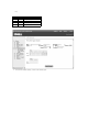
Front-Panel Components
The front panel of the switch contains the console port, all of the Ethernet ports, and LEDs. As shown in the following figure, the switch has three system
LEDs and one LED for each port. The following sections describe the front panel in more detail.
PWR LED
The PWR (power) LED shows the general operating status of the system. Indicator states include:
l
Off — The unit is off with no power connections.
l
Green — The unit's internal power supply is operating normally.
l
Red — The unit's internal power supply has failed.
RPS LED
The RPS LED shows the operating status of a connected redundant power unit. Indicator states include:
l
Off — The RPS is not connected.
l
Green — The RPS is operating normally.
l
Red — The RPS has failed.
DIAG LED
The diagnostic (DIAG) LED shows the status of the system diagnostics during initialization. Indicator states include:
l
Blinking green — The system diagnostic test is in progress.
l
Green — The system diagnostic test has completed successfully.
l
Red — The system diagnostic test has detected a fault.
Console Port
You can access the console interface from the RS-232 serial port or a Telnet connection. The console port uses a standard null-modem cable. For instructions
on configuring your switch using the console, see "Management Interface."
Port LEDs
Two of the LEDs show the operating status of each Gigabit Ethernet port, and the other LED shows the operating status of each SFP transceiver slot. Details
of the LED indications are provided in each of the following sections.
Gigabit Ethernet Ports
Link Status and Activity (LINK/ACT)
l
Green — A 1000-megabits per second (Mbps) link is up and there is no activity.
l
Blinking green — A 1000-Mbps link is up and there is activity.
l
Orange — A 10/100-Mbps link is up and there is no activity.
l
Blinking orange — A 10/100-Mbps link is up and there is activity.
l
Flashing orange — The link is in the admin down state.
l
Off — The link is down.
Duplex Mode (FDX)
l
Green — A full-duplex link is up.
l
Off — A half-duplex link is up.
SFP Transceiver Ports
SFP Transceiver Status
l
Green — An SFP transceiver is correctly installed in the slot and has a valid link on the port.
l
Off — An SFP transceiver has no valid link on its port or is not installed in the slot.
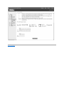
Back-Panel Descriptions
The back panel of the system contains the AC power receptacle and the RPS connector.
AC Power Receptacle
The switch automatically adjusts its power setting to any supply voltage in the range of 90 to 240 V alternating current (VAC).
RPS Connector
Connect the optional RPS to the RPS connector. If the switch's internal power unit fails, the redundant power system automatically supplies power to the
switch for uninterrupted operation.
The switch supports the Dell PowerConnect RPS-600 external redundant power system.
NOTE: See the RPS-600 documentation for more information.
CAUTION: Do not use this switch with any redundant power system other than the Dell PowerConnect RPS-600.
Management
The following sections describe options for managing the switch.
Web-Based Interface
NOTE: To access the switch through a web browser, the computer running the web browser must have IP-based network access to the switch.
After you have successfully installed the switch, you can configure the switch, monitor the LED panel, and display statistics graphically using a web browser,
such as Netscape Navigator (version 6.2 and higher) or Microsoft® Internet Explorer (version 5.0).
Command-Line-Driven Console Interface Through a Serial Port or Telnet
You can also connect a computer or terminal to the serial console port or use Telnet to access the switch. The command-line-driven interface provides
complete access to all switch management features. Most of the common commands are described in "Management Interface." For a full list of commands, see
the Command Line Reference, which is included on the documentation CD.
SNMP-Based Management
You can manage the switch with an SNMP-compatible console program. The switch is compatible with SNMP version 1.0 and 2.0c.
The SNMP agent decodes the incoming SNMP messages and responds to requests with MIB objects stored in the database. The SNMP agent updates the MIB
objects every 5 seconds to generate statistics and counters.
The switch supports a comprehensive set of MIB extensions:
l
RFC 1213 MIB II
l
RFC 2863 Interfaces Evolution MIB
l
RFC 2665 Ethernet-Like MIB
l
RFC 1493 Bridge MIB
l
RFC 2674 Extended Bridge MIB
l
RFC 2819 RMON MIB
l
RFC 2737 Entity MIB
l
RFC 2618 RADIUS authentication client MIB
l
Dell PowerConnect 5212 Private MIB
Back to Contents Page
Back to Contents Page
Installation
Dell™ PowerConnect™ 5212 Systems User's Guide
Package Contents
Password Protection
Before You Connect to the Network: Mounting Kit Instructions
SNMP Settings
External Redundant Power System
IP Address Assignment
Connecting the Console Port
Connecting Devices to the Switch
Package Contents
Before you begin installing the switch, confirm that your package contains the following items:
l
Switch
l
AC power cable
l
Null modem cable
l
Self-adhesive rubber pads for desktop installation
l
Rack mount kit for rack installation
l
Documentation CD
Before You Connect to the Network: Mounting Kit Instructions
NOTICE: Do not connect the switch to the network until you have established the correct Internet Protocol (IP) settings.
Before you connect to the network, you must install the switch on a flat surface or in a rack, set up a terminal emulation program, plug in the power cord, and
then set up a password and IP address.
The switch is supplied with rubber feet for stationing it on a flat surface and mounting brackets and screws for mounting the switch in a rack.
Installing the Switch Without the Rack
Install the switch on a level surface that can safely support the weight of the switch and its attached cables. The switch must have adequate space for
ventilation and for accessing cable connectors.
1.
Set the switch on a flat surface and check for proper ventilation.
Allow at least 2 inches (5.1 centimeters [cm]) on each side of the switch and 5 inches (12.7 cm) at the back for the power cable.
2.
Attach the rubber feet on the marked locations on the bottom of the chassis.
The rubber feet, although optional, are recommended to keep the unit from slipping.
Installing the Switch in a Rack
You can install the switch in most standard 19-inch (48.3-cm) racks.
NOTE: For racks that are not prethreaded, cage nuts are provided.
1.
Use the supplied screws to attach a mounting bracket to each side of the switch.
2.
Align the holes in the mounting bracket with the holes in the rack.
3.
Insert and tighten two screws through each of the mounting brackets.
External Redundant Power System
The switch supports the Dell PowerConnect RPS-600 external redundant power system.
NOTE: See the RPS-600 documentation for more information.
CAUTION: Do not use the switch with any redundant power system other than the Dell PowerConnect RPS-600.
Connecting the Console Port
The switch provides an RS-232 serial port that enables a connection to a computer or terminal for monitoring and configuring the switch. This port is a male
DB-9 connector, implemented as a data terminal equipment (DTE) connection.
To use the console port, you need the following equipment:
l
A terminal or a computer with both a serial port and the ability to emulate a terminal
l
A null modem or crossover RS-232 cable with a female DB-9 connector for the console port on the switch
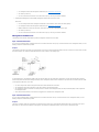
To connect a terminal to the console port:
1.
Connect the female connector of the RS-232 cable directly to the console port on the switch, and tighten the captive retaining screws.
2.
Connect the other end of the cable to a terminal or to the serial connector of a computer running terminal emulation software.
Set the terminal emulation software as follows:
a.
Select the appropriate serial port (COM port 1 or COM port 2).
b.
Set the data rate to 9600 baud.
c.
Set the data format to 8 data bits, 1 stop bit, and no parity.
d.
Set flow control to none.
e.
Under Properties, select VT100 for Emulation mode.
f.
Select Terminal keys for Function, Arrow, and Ctrl keys. Ensure that you select Terminal keys (not Windows keys).
NOTICE: When you use HyperTerminal with the Microsoft® Windows® 2000 operating system, ensure that you have Windows 2000 Service Pack 2 or
later installed. Windows 2000 Service Pack 2 allows you to use arrow keys in HyperTerminal's VT100 emulation. See www.microsoft.com for
information on Windows 2000 service packs.
3.
After you have correctly set up the terminal, plug the power cable into the power receptacle on the back of the switch. The boot sequence appears in
the terminal.
After the boot sequence completes, the console login screen displays. If you have not logged into the command line interface (CLI) program, the default
user names are admin and guest, and the corresponding passwords are admin and guest.
4.
l
If you log in as guest, the CLI displays the Console> prompt to indicate that you are using the CLI in normal access (Normal Exec) mode.
l
If you log in as admin, the CLI displays the Console# prompt to indicate that you are using the CLI in privileged access (Privileged Exec) mode.
Enter the commands to complete your desired tasks. Many commands require Privileged Exec-level access.
CLI commands for most common tasks are provided in "Management Interface." See the Command Line Reference on the documentation CD for a list of
all commands and additional information on using the CLI.
5.
When you have completed your tasks, exit the session with the Quit command.
Password Protection
To proceed through the CLI initial login screen, you must enter a password. If you have not logged into the CLI program, the default user names are admin
and guest, and the corresponding passwords are admin and guest. If you log in as guest, you have access to the Normal Exec level. If you log in as admin, you
have access to the Privileged Exec level.
User Access Verification
Username: admin
Password:
CLI session with the PowerConnect 5212 is opened.
To end the CLI session, enter [Exit].
Console#
After your initial login, define new passwords for both default user names to prevent unauthorized access to the switch, and record the passwords for future
reference.
1.
At the CLI login prompt, enter admin as the user name and password for the Privileged Exec level. Press <Enter>.
2.
Type configure and press <Enter>.
NOTE: Passwords are case sensitive.
3.
To set the Normal Exec level password, type username guest password 0 password, where password is your new password (up to eight characters).
Press <Enter>.
4.
To set the Privileged Exec level password, type username admin password 0 password, where password is your new password (up to eight characters).
Press <Enter>.
5.
To save your configuration changes, type copy running-config startup-config and then press <Enter>.
NOTICE: CLI configuration commands only modify the running configuration file and are not saved when the switch is rebooted. To save all your
configuration changes in nonvolatile storage, you must use the copy command to copy the running configuration file to the startup configuration.
SNMP Settings
Simple Network Management Protocol (SNMP) is a protocol designed specifically for managing devices on a network. Network equipment, such as hubs,
switches, and routers, use SNMP to configure system features for proper operation, as well as to monitor their performance and detect potential problems.
Managed devices that support SNMP include software (referred to as an agent), which runs locally on the device. A defined set of variables (managed objects)
is maintained by the SNMP agent and used to manage the device. These objects are defined in a Management Information Base (MIB), which provides a
standard presentation of the information controlled by the agent. SNMP defines both the format of the MIB specifications and the protocol used to access this
information over the network.
The PowerConnect 5212 switch includes an on-board SNMP agent that monitors the status of the switch hardware, as well as the traffic passing through the
ports. A computer on the network running SNMP-based management software, called a Network Management Station (NMS), can be used to access this
information. Access rights to the SNMP agent are controlled by community strings. To communicate with the switch, the NMS must first submit a valid
community string for authentication.
The default community strings for the switch are:
l
Public — Allows authorized management stations to retrieve MIB objects.
l
Private — Allows authorized management stations to retrieve and modify MIB objects.
If you do not intend to utilize SNMP, delete both of the default community strings. SNMP management access to the switch is disabled if no community strings
exist. To delete the strings:
1.
If you are not already in the Privileged Exec level global configuration mode, type configure and press <Enter>.
2.
To delete the private community string, type no snmp-server community private and then press <Enter>.
3.
To delete the public community string, type no snmp-server community public and then press <Enter>.
4.
To save your configuration changes, type copy running-config startup-config and then press <Enter>.
If you do intend to utilize SNMP, change the default community strings to prevent unauthorized access to the switch:
1.
If you are not already in the Privileged Exec level global configuration mode, type configure and press <Enter>.
2.
To delete the existing private community string, type no snmp-server community private and then press <Enter>.
3.
Type snmp-server community string rw, where string is your new community string (case sensitive) for read-write access. Press <Enter>.
4.
To delete the existing public community string, type no snmp-server community public and then press <Enter>
5.
Type snmp-server community string ro, where string is your new community string (case sensitive) for read-only access. Press <Enter>.
6.
To save your configuration changes, type copy running-config startup-config and then press <Enter>.
IP Address Assignment
You must assign an IP address to the switch to gain management access over the network. You may also need to a establish a default gateway between the
switch and management stations that exist on another network segment. You can statically configure a specific IP address or direct the switch to obtain an
address from a Boot Protocol (BOOTP) or Dynamic Host Configuration Protocol (DHCP) server when it is powered on. Valid IP addresses consist of four decimal
numbers, 0 to 255, separated by periods. Anything outside this format is not accepted by the CLI program.
NOTICE: By default, the IP address is assigned to VLAN 1 through DHCP.
If you select the bootp or dhcp option, IP is enabled but does not function until a BOOTP or DHCP reply has been received. Requests are broadcast
periodically by the switch in an effort to learn its IP address. (BOOTP and DHCP values can include the IP address, default gateway, and subnet mask).
To display assigned IP settings using the CLI:
1.
From the Privileged Exec or Normal Exec level mode, type show ip interface and press <Enter>.
The assigned IP address and subnet mask displays.
2.
From the Privileged Exec mode, type show ip redirects to display the assigned gateway IP address. Press <Enter>.
The following example displays IP settings assigned by bootp or dhcp using the CLI.
Console#show ip interface
IP address and netmask: 10.1.0.1 255.255.252.0 on VLAN 1,
and address mode: User specified.
Console# show ip redirects
ip default gateway 10.1.0.254
Console#
Before you can assign a static IP address to the switch, you must obtain the following information from your network administrator:
l
IP address for the switch
l
Default gateway for the network
l
Network mask for the network
To assign a static IP address to the switch:
1.
From the Privileged Exec level global configuration mode prompt, type interface vlan 1 to access the interface-configuration mode. Press <Enter>.
2.
Type ip address ip-address netmask, where ip-address is the switch IP address and netmask is the network mask for the network.
3.
Type exit to return to the global configuration mode prompt. Press <Enter>.
4.
To set the IP address of the default gateway for the network to which the switch belongs, type ip default-gateway gateway, where gateway is the IP
address of the default gateway. Press <Enter>.
5.
To save your configuration changes, type copy running-config startup-config and then press <Enter>.
NOTICE: Only one VLAN can be assigned an IP address. If you assign an address to any other VLAN, the new address overrides the original IP
address.
The following example shows how to set a static IP address using the CLI.
Console(config)# interface vlan 1
Console(config-if)# ip address 192.168.1.5 255.255.255.0
Console(config-if)# exit
Console(config)# ip default-gateway 192.168.1.254
Console(config)#
To configure the switch for DHCP or BOOTP:
1.
From the Privileged Exec level global configuration mode prompt, type interface vlan 1 to access the interface-configuration mode. Press <Enter>.
2.
At the next prompt, use one of the following commands:
l
To obtain IP settings through DHCP, type ip address dhcp
l
To obtain IP setting through BOOTP, type ip address bootp
3.
Press <Enter>.
4.
To save your configuration changes, type copy running-config startup-config, and then press <Enter>.
Connecting Devices to the Switch
After you assign IP addresses to the switch, you can connect devices to the RJ-45 connectors on the switch.
NOTICE: If autonegotiation is disabled for an RJ-45 port, the auto-MDI/MDI-X pin signal configuration is also disabled.
To connect a device to an SFP transceiver port:
1.
Use your cabling requirements to select an appropriate SFP transceiver type.
2.
Insert the SFP transceiver (sold separately) into the SFP transceiver slot.
3.
Use the appropriate network cabling to connect a device to the connectors on the SFP transceiver. The slot's LED indicator turns on to confirm that it is
correctly installed and operating.
NOTICE: When the SFP transceiver acquires a link, the associated integrated 10/100/1000BASE-T port is disabled.
Back to Contents Page
Back to Contents Page
Management Interface
Dell™ PowerConnect™ 5212 Systems User's Guide
Web Pages
VLAN
System
Class of Service
Switch
Link Aggregation
Ports
SNMP
Address Table
Multicast Support
Spanning Tree
Statistics
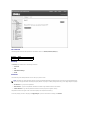
With web-based management, you can configure the PowerConnect 5212 Gigabit Ethernet Managed Switch and monitor the system using a web browser.
Most pages for the switch include the following buttons:
l
Refresh — Displays the current values for the system related to the page that is open.
l
Apply Changes — Makes changes to the system and refreshes the page.
NOTICE: For configuration changes to persist beyond the current session, you must either save the running-config file from the Switch/Configuration
page or use the command line interface (CLI) command copy running-config startup-config.
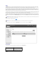
Web Pages
When you connect to the management mode of the switch with a web browser, a login screen is displayed. Enter a user name and password to access the
switch's management mode.
NOTE: The default user names are admin and guest, and the corresponding passwords are admin and guest. If you log in as guest (Normal Exec level),
you can only view page information and change the guest password. If you log in as admin (Privileged Exec level), you can apply changes on all pages.
The following menus are available from the web interface:
l
Switch
l
Ports
l
Address Table
l
Spanning Tree
l
VLAN
l
Class of Service
l
Link Aggregation
l
SNMP
l
Multicast Support
l
Statistics
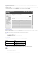
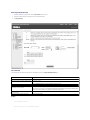
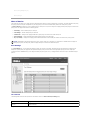
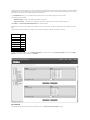
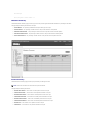
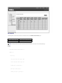
System
The System page contains a dynamic switch applet that displays the current status of the switch ports. The color of each switch port icon indicates its link
status:
l
Green — The link is up.
l
Grey — The link is down.
Clicking on any port icon displays the port configuration page.
Switch
The Switch page contains all system operations and general information. It includes links to the following options:
l
General — Allows you to view general system information and perform general administration
l
IP Address — Allows you to view or edit Internet Protocol (IP) parameters
l
Security — Allows you to set the password for your login username and configure authentication settings for secure management access
l
Jumbo Frame — Allows you to enable jumbo frame support on the switch
l
Firmware — Allows you to transfer a firmware upgrade to the switch
l
Configuration — Allows you to save or restore switch configuration files
l
Reset — Allows you to reboot the switch
General Information
The General page contains links to the following pages:
l
Asset
l
Health
l
Versions
l
System Logs
l
Logs
l
Remote Logs
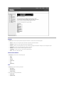
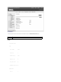
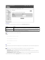
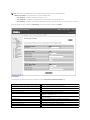
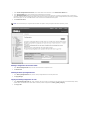
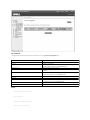
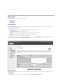
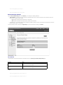
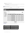
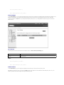
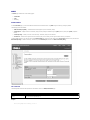
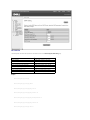
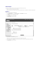
Asset
The Asset page contains the following information:
l
MAC Address
l
SNMP Object ID
l
System Up Time
It also includes the following editable fields:
l
System Name
l
System Contact
l
System Location
To save any changes you make in this page, click Apply Changes. If you don't want to save the changes, click Refresh.
CLI Commands
The following table summarizes the equivalent CLI commands for items in the Switch/General/Asset page.
Command
Usage
show system
Displays system information
hostname name
Specifies or modifies the system name for this device
snmp-server contact string
Sets the system contact (sysContact) string
snmp-server location text
Sets the system location string
Example
Console(config)#hostname Server Chassis 35
Console(config)#snmp-server contact Paul
Console(config)#snmp-server location WC-19
Console(config)#exit
Console#show system
System description: PowerConnect 5212
System OID string: 1.3.6.1.4.1.674.10895.4
System information
System Up time: 0 days, 0 hours, 14 minutes, and 17.93 seconds System Name : Server Chassis 35 System Location : WC-19
System Contact : Paul MAC address : 00-00-e8-00-00-02
Web server : enable Web server port : 80 Web secure server : enable Web secure server port : 443 POST result : --- Performing Power-On Self Tests (POST) -- UART Loopback Test ..................... PASS
Timer Test ............................. PASS
DRAM Test .............................. PASS
I2C Initialization ..................... PASS
Runtime Image Check .................... PASS
PCI Device Check ....................... PASS
Switch Driver Initialization ........... PASS
Switch Internal Loopback Test .......... PASS
------------------- DONE ------------------- Console#
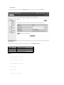
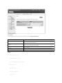
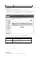
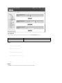
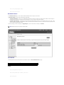
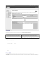
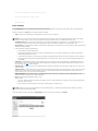
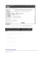
Health
The Health page contains the following information:
l
Internal Power Status
l
Redundant Power Status
The power status is indicated by the following icons:
l
Green check — Power is connected and operating.
l
Red cross — Power is connected but has failed.
l
Not present — Power is not connected.
To reset these fields to their current value, click Refresh.
CLI Commands
The following table summarizes the equivalent CLI command for items in the Switch/General/Health page.
Command
Usage
show version Displays hardware and software version information for the system, as well as the unit's power status
Example
Console#show version
Unit1
Serial number :123457 Service tag :3 Hardware version :/2002 Number of ports :12 Main power status :up Redundant power status :up Agent(master)
Unit id :1 Loader version :1.0.0.0 Boot rom version :1.0.0.2 Operation code version :0.0.0.5 Console#
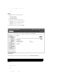
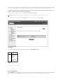
Versions
The Versions page contains the following fields:
l
Hardware Version
l
Microcode Version
l
Loader Version
l
Boot-ROM Version
l
Operation Code Version
l
Total Port Number
l
Role
l
Service Tag
l
Serial Number
CLI Commands
The following table summarizes the equivalent CLI command for items in the Switch/General/Versions page.
Command
Usage
show version Displays hardware and software version information for the system, as well as the unit's power status
Example
Console#show version
Unit1
Serial number :123457 Service tag :3 Hardware version :/2002 Number of ports :12 Main power status :up Redundant power status :up Agent(master)
Unit id :1 Loader version :1.0.0.0 Boot rom version :1.0.0.2 Operation code version :0.0.0.5 Console#
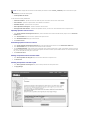
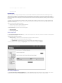
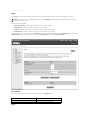
System Logs Configuration
The system can be configured to send debug and error messages to a logging process. This logging process controls the type of error messages that are
stored in switch memory or sent to a remote syslog server.
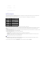
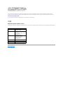
The system log messages are categorized by severity into eight levels, from 0 (Emergencies) to 7 (Debugging). See the following table:
Level Argument Level Description
Emergencies
0
System unusable
Alerts
1
Immediate action needed
Critical
2
Critical conditions
Errors
3
Error conditions
Warnings
4
Warning conditions
Notifications
5
Normal but significant condition
Informational
6
Informational messages only
Debugging
7
Debugging messages
The system allows you to specify which levels are logged to random access memory (RAM) or flash memory.
Severe error messages that are logged to flash memory are permanently stored in the switch to assist in troubleshooting network problems. Up to 4096 log
entries can be stored in the flash memory, with the oldest entries being overwritten first when the available memory for logs (256 kilobyte) has been
exceeded.
The Switch/General/System Logs page allows you to configure and limit system messages that are logged to flash or RAM memory. The default is for levels
0 to 3 to be logged to flash and levels 0 to 7 to be logged to RAM.
The Switch/General/System Logs page contains the following editable fields:
l
System Log Status — Enables/disables the logging of debug or error messages to the logging process.
l
Flash Level — Limits log messages saved to the switch's permanent flash memory for all levels up to the specified level. For example, if level 3 is
specified, all messages from level 0 to level 3 will be logged to flash.
NOTE: The Flash Level must be equal to or less than the Ram Level.
l
Ram Level — Limits log messages saved to the switch's temporary RAM memory for all levels up to the specified level. For example, if level 7 is
specified, all messages from level 0 to level 7 will be logged to RAM.
To save any changes you make in this page, click Apply Changes. If you don't want to save the changes, click Refresh.
CLI Commands
The following table summarizes the equivalent CLI commands for items in the Switch/General/System Logs page.
Command
Usage
logging on
Controls the logging of debug or error messages to a logging process.
The no form disables the logging process.
logging history {flash | ram} level Limits syslog messages saved to switch memory based on severity.
The no form returns the logging of syslog messages to the default level.
flash — Event history stored in flash memory (permanent memory).
ram — Event history stored in temporary RAM (memory flushed on power reset).
show logging {flash | ram | trap}
Displays the logging configuration for system and event messages.
Example
Console(config)#logging on
Console(config)#logging history ram 0
Console(config)#
Console#show logging flash
Syslog logging: Disable
History logging in FLASH: level errors
Console#
Logs
The Logs page allows you to scroll through the logged system and event messages. The switch can store up to 2048 log entries in temporary RAM (memory
flushed on power reset) and up to 4096 entries in permanent flash memory.
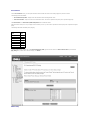
Remote Logs Configuration
The Switch/General/Remote Logs page allows you to configure the logging of messages that are sent to syslog servers or other management stations. You
can also limit the error messages sent to only those messages of a specified level.
The Switch/General/Remote Logs page contains the following editable fields:
l
Remote Log Status — Enables/disables the logging of debug or error messages to the remote logging process. (Default: enabled)
l
Logging Facility — Sets the facility type for remote logging of syslog messages. There are eight facility types specified by values of 16 to 23. The facility
type is used by the syslog server to dispatch log messages to an appropriate service. (Default: 23)
l
Logging Trap — Limits log messages that are sent to the remote syslog server for all levels up to the specified level. For example, if level 3 is specified,
all messages from level 0 to level 3 will be sent to the remote server. (Default: 3)
l
Host IP List — Displays the list of remote server IP addresses that receive the syslog messages. The maximum number of host IP addresses allowed is
five.
l
Host IP Address — Specifies a new server IP address to add to the Host IP List.
To add an IP address to the Host IP List, type the new IP address in the Host IP Address box, and then click Add IP Host. To delete an IP address, click the
entry in the Host IP List, and then click Remove Host IP.
To save any changes you make in this page, click Apply Changes. If you don't want to save the changes, click Refresh.
CLI Commands
The following table summarizes the equivalent CLI commands for items in the Switch/General/Remote Logs page.
Command
Usage
logging host host_ip_address
Adds a syslog server host IP address that will receive logging messages.
Use the no form to remove a syslog server host.
logging facility facility_type
Sets the facility type for remote logging of syslog messages.
The no form returns the type to the default.
logging trap level
Limits syslog messages saved to a remote server based on severity.
The no form returns the remote logging of syslog messages to the default level.
show logging {flash | ram | trap} Displays the logging configuration for system and event messages
Example
Console(config)#logging host 10.1.0.9
Console(config)#logging facility 23
Console(config)#logging trap 4
Console(config)#
Console#show logging trap
Syslog logging: Enable
REMOTELOG status: enable
REMOTELOG facility type: local use 7
REMOTELOG level type: Warning conditions
REMOTELOG server ip address: 10.1.0.9
REMOTELOG server ip address: 0.0.0.0
REMOTELOG server ip address: 0.0.0.0
REMOTELOG server ip address: 0.0.0.0
REMOTELOG server ip address: 0.0.0.0
Console#
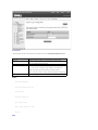
IP Address
The IP Address page contains links to the following pages:
l
IP Address
l
DHCP
IP Address
From the IP Address page, you can manage the IP-related information about the system. The page includes the following editable fields:
l
Management VLAN — Sets the virtual local area network (VLAN) interface that allows management access to the switch. You can set the IP
address for only one VLAN interface.
l
IP Address Mode — Sets whether IP functionality is enabled through manual (Static) configuration or set by Dynamic Host Configuration Protocol
(DHCP) or Boot Protocol (BOOTP).
l
IP Address — Identifies the IP address of the VLAN interface that allows management access to the switch.
l
Subnet Mask — Identifies the subnet mask that determines the host address bits used for routing to specific subnets.
l
Gateway IP Address — Identifies the IP address of the gateway router between the switch and management stations that exist on other
network segments.
NOTICE: When DHCP or BOOTP has been used to set the IP information, the IP Address, Subnet Mask, and Gateway IP Address fields display the
assigned values.
The Management VLAN is the only VLAN through which you can gain management access to the switch. By default, all ports on the switch are members of
VLAN 1, so a management station can be connected to any port on the switch. If other VLANs are configured and you change the Management VLAN, you may
lose management access to the switch. In this case, you should reconnect the management station to a port that is a member of the Management VLAN. For
more information on the Management VLAN, see "Management VLAN Access."
To save any changes you make in this page, click Apply Changes. If you don't want to save the changes, click Refresh.
CLI Commands
The following table summarizes the equivalent CLI commands for items in the Switch/IP Address page.
Command
Usage
ip address {ip-address netmask |
bootp | dhcp}
Sets the primary IP address for this device. Use the no form command to remove the IP address, or to disable IP
address assignment through BOOTP or DHCP.
ip default-gateway gateway
Establishes a static route between the switch and management stations that exist on another network segment.
show ip interface
Displays the usability status of an IP interface.
show ip redirects
Shows the default gateway configured for this device.
Example
Console(config)#interface vlan 1
Console(config-if)#ip address 192.168.1.5 255.255.255.0
Console(config-if)#exit
Console(config)#ip default-gateway 192.168.1.254
Console(config)#
DHCP
In the DHCP page, click Restart DHCP to release the current IP address and obtain a new one through DHCP.
NOTICE: If Restart DHCP is selected when IP settings have been configured statically, a warning message indicating that the IP Address Mode is not
set to DHCP displays.
CLI Commands
The following table summarizes the equivalent CLI command for items in the Switch/IP Address/DHCP page.
Command
Usage
ip dhcp restart Resubmits a DCHP client request
Security
The Security page contains links to the following information:
l
Passwords
l
SSH
l
Authentication Settings
l
HTTPS
Passwords
You should change the default passwords to be sure that your system is secure:
NOTE: The default user names are admin and guest, and the corresponding passwords are admin and guest. If you log in as guest (Normal Exec level),
you can only view page information and change the guest password. If you log in as admin (Privileged Exec level), you can apply changes on all pages.
l
Old Password — Type your current password.
l
New Password — Type the new password. Passwords are limited to eight characters and are case sensitive.
l
Confirm Password — Type the new password a second time to verify that you have typed it correctly.
The password entered is encrypted on the screen and is displayed as a sequence of asterisks (*).
To save any changes you make in this page, click Apply Changes. If you don't want to save the changes, click Refresh.
CLI Commands
The following table summarizes the equivalent CLI commands for items in the Switch/Security/Passwords page.
Command
Usage
enable password [level level] {0 |
7} password
Use this command to control access to the Privileged Exec level from the Normal Exec level. For the {0 | 7} parameter,
0 means plain password and 7 means encrypted password. The Privileged Exec level is 15 and the default password is
super.
username name {access-level level | Use this command to configure user name authentication at login. Use the no form command to remove a user name.
nopassword | password {0 | 7}
The device has two predefined privilege levels: 0: Normal Exec and 15: Privileged Exec. The default user names are
password}
admin for the Privileged Exec level, and guest for the Normal Exec level.
NOTE: Only the CLI allows user names to be created and deleted.
Example
Console(config)#enable password level 15 0 admin
Console(config)#username bob access-level 15
Console(config)#username bob password smith
Console(config)#
SSH
The Secure Shell (SSH) server feature provides remote management access via encrypted paths between the switch and SSH-enabled management station
clients.
NOTE: There are two versions of the SSH protocol currently available, SSH v1.x and SSH v2.x. The switch supports only SSH v1.5.
l
SSH Server Status — Allows you to enable/disable the SSH server feature on the switch (Default: enabled)
l
SSH authentication timeout — Specifies the time interval in seconds that the SSH server waits for a response from a client during an authentication
attempt (Range: 1 to 120 seconds; Default: 120 seconds)
l
SSH authentication retries — Specifies the number of authentication attempts that a client is allowed before authentication fails and the client has to
restart the authentication process (Range: 1 to 5 times; Default: 3)
To save any changes you make in this page, click Apply Changes. If you don't want to save the changes, click Refresh.
CLI Commands
The following table summarizes the equivalent CLI commands for items in the Switch/Security/SSH page.
Command
Usage
ip ssh server
Enables the SSH server on the switch.
Use the no form to disable the SSH server.
ip ssh {[timeout seconds] | [authentication-retries
integer]}
Specifies the authentication timeout for the SSH server and the number of retries allowed by a client.
Use the no form to reset the values to the default.
disconnect ssh connection_id
Terminates an SSH connection. The connection_id is the session number displayed when using the
show ssh command.
show ip ssh
Displays the status of the SSH server and the configured values for authentication timeout and
retries.
show ssh
Displays the status of current SSH sessions.
Example
Console(config)#ip ssh server
Console(config)#ip ssh timeout 100
Console(config)#ip ssh authentication-retries 5
Console(config)#
Console#show ip ssh
Information of secure shell
SSH status: enable
SSH authentication timeout: 100
SSH authentication retries: 5
Console#show ssh
Information of secure shell
Session Username Version Encrypt method Negotiation state
------- -------- ------- -------------- ---------------- 0 admin 1.5 cipher-3des session-started
Console#
Authentication Settings
Remote Authentication Dial-in User Service (RADIUS) and Terminal Access Controller Access Control System Plus (TACACS+) are systems that use a central
server to control access to switches on a network. A server running RADIUS or TACACS+ software can be used to create a database of multiple user
name/password pairs with associated privilege levels for each user or group that require management access to a switch using the console port, Telnet, or
Internet.
The RADIUS system uses UDP while TACACS+ uses TCP. UDP only offers best effort delivery, while TCP offers a connection-oriented transport. Also, note that
RADIUS encrypts only the password in the access-request packet from the client to the server, while TACACS+ encrypts the entire body of the packet.
Both RADIUS and TACACS+ authentication control management access via the console port, Web browser, or Telnet. These access options must be configured
on the authentication server together with user names, passwords, and specific privilege levels for each user name/password pair.
NOTE: When you are setting up privilege levels on a RADIUS or TACACS+ server, level 0 allows Normal Exec access to the switch, and level 15 allows
Privileged Exec access.
The Switch/Security/Authentication Settings page contains the following editable fields:
l
l
Authentication Sequence — Select the authentication, or authentication sequence, required: (Default: local)
¡
Local — The switch authenticates the user.
¡
RADIUS — A RADIUS server authenticates the user.
¡
TACACS — A TACACS+ server authenticates the user.
¡
Local, RADIUS — The switch attempts to authenticate the user first, and then a RADIUS server attempts to authenticate the user.
¡
Local, TACACS — The switch attempts to authenticate the user first, and then a TACACS+ server attempts to authenticate the user.
¡
RADIUS, Local — A RADIUS server attempts to authenticate the user first, and then the switch attempts to authenticate the user.
¡
RADIUS, TACACS — A RADIUS server attempts to authenticate the user first, and then a TACACS+ server attempts to authenticate the user.
¡
Local, RADIUS, TACACS — The switch attempts to authenticate the user first, then a RADIUS server, and then a TACACS+ server.
¡
Local, TACACS, RADIUS — The switch attempts to authenticate the user first, then a TACACS+ server, and then a RADIUS server.
¡
RADIUS, Local, TACACS — A RADIUS server attempts to authenticate the user first, then the switch, and then a TACACS+ server.
¡
RADIUS, TACACS, Local — A RADIUS server attempts to authenticate the user first, then a TACACS+ server, and then the switch.
¡
TACACS, Local, RADIUS — A TACACS+ server attempts to authenticate the user first, then the switch, and then a RADIUS server.
¡
TACACS, RADIUS, Local — A TACACS+ server attempts to authenticate the user first, then a RADIUS server, and then the switch.
RADIUS Server Settings — If using a RADIUS server, specify the following details:
¡
Server IP Address — Identifies the IP address of the RADIUS server.
¡
Server Port Number — Identifies the User Datagram Protocol (UDP) port number used by the RADIUS server.
¡
Secret Text String — Specifies the text string that is shared between the switch and the RADIUS server. Do not use blank spaces in the string.
¡
Number of Server Transmits — Specifies the number of request transmits to the RADIUS server before failure.
¡
Timeout for a Reply — Specifies the number of seconds the switch waits for a reply from the RADIUS server before it resends the request.
NOTE: The local switch user database must be set up through the CLI by manually entering user names and passwords.
l
TACACS+ Server Settings — If using a TACACS+ server, specify the following details:
¡
Server IP Address — Identifies the IP address of the TACACS+ server.
¡
Server Port Number — Identifies the User Datagram Protocol (UDP) port number used by the TACACS+ server.
¡
Secret Text String — Specifies the text string that is shared between the switch and the TACACS+ server. Do not use blank spaces in the string.
To save any changes you make in this page, click Apply Changes. If you don't want to save the changes, click Refresh.
CLI Commands
The following table summarizes the equivalent CLI commands for items in the Switch/Security/Authentication Settings page.
Command
Usage
authentication login {radius | local | tacacs} [tacacs | radius | local] Defines the login authentication method and precedence.
[local | tacacs | radius]
radius-server host host_ip_address
Specifies the RADIUS server IP address.
radius-server port port_number
Sets the RADIUS server UDP port number.
radius-server key key_string
Sets the RADIUS encryption key (up to 20 characters).
radius-server retransmit number_of_retries
Sets the number of times the switch attempts to authenticate logon access through the
RADIUS server. (The range is 1–30.)
radius-server timeout number_of_seconds
Sets the number of seconds the switch waits for a reply before resending a request.
(The range is 1-65535.)
show radius-server
Displays the current configuration of the RADIUS server parameters.
tacacs-server host host_ip_address
Specifies the TACACS+ server IP address.
tacacs-server port port_number
Sets the TACACS+ server UDP port number.
tacacs-server key key_string
Sets the TACACS+ encryption key (up to 20 characters).
show tacacs-server
Displays the current configuration of the TACACS+ server parameters.
Example
Console(config)#authentication login local radius tacacs
Console(config)#radius-server host 192.168.1.25
Console(config)#radius-server port 181
Console(config)#radius-server key green
Console(config)#radius-server retransmit 5
Console(config)#radius-server timeout 10
Console(config)#tacacs-server host 192.168.1.19
Console(config)#tacacs-server port 49
Console(config)#tacacs-server key tiger
Console(config)#
Console#show tacacs-server
Remote TACACS server configuration:
Server IP address: 192.168.1.19
Communication key with radius server: tiger
Server port number: 49
Console#
HTTPS
Use the Switch/Security/HTTPS page to enable the Secure Hypertext Transfer Protocol (HTTPS) over the Secure Socket Layer (SSL), providing secure access
(i.e., an encrypted connection) to the switch's Web interface.
Both the HTTP and HTTPS service can be enabled independently on the switch. However, you cannot configure the HTTP and HTTPS servers to use the same
UDP port. If you change the HTTPS port number, clients attempting to connect to the HTTPS server must specify the port number in the URL, in this
format: https://device:port_number.
NOTE: If you enable HTTPS, you must indicate this in the URL. For example: https://device [:port_number]
The following Web browsers and operating systems currently support HTTPS:
Web Browser
Operating System
Internet Explorer 5.0 or later
Microsoft® Windows® 98, Microsoft Windows NT®(with service pack 6a), Windows 2000
Netscape Navigator 4.76 or later Windows 98, Windows NT (with service pack 6a), Windows 2000, Solaris 2.6
When you start HTTPS, the client and server establish a secure encrypted connection. A padlock icon should appear in the status bar for Internet Explorer 5.x
and Netscape Navigator 4.x.
The Switch/Security/HTTPS page contains the following editable fields:
l
HTTPS Status — Allows you to enable/disable the HTTPS server feature on the switch. (Default: enabled)
l
HTTPS Port — Specifies the UDP port number used for HTTPS/SSL connection to the switch's Web interface. The default is port 443.
To save any changes you make in this page, click Apply Changes. If you don't want to save the changes, click Refresh.
CLI Commands
The following table summarizes the equivalent CLI commands for items in the Switch/Security/HTPS page.
Command
Usage
ip http secure-server
Enables the HTTPS server on the switch.
Use the no form to disable the HTTPS server.
ip http secure-port port_number
Specifies the UDP port number used for HTTPS connection to the switch's Web interface.
Use the no form to restore the default port.
copy tftp https-certificate
Copies an HTTPS certificate from a TFTP server to the switch.
Example
Console(config)#ip http secure-server
Console(config)#ip http secure-port 441
Console(config)#
Jumbo Frame
From the Jumbo Frame page, you can enable and disable jumbo frame support on the switch.
The switch provides more efficient large sequential data transfers by supporting jumbo frames up to 9000 bytes. Compared to standard Ethernet frames that
run only up to 1500 bytes, using jumbo frames significantly reduces the per-packet overhead required to process protocol encapsulation fields.
To use jumbo frames, both the source and destination end nodes (such as a computer or server) must support jumbo frames. In addition, when the
connection is operating at full duplex, all switches in the network between the two end nodes must be able to accept the extended frame size. For half-duplex
connections, all devices in the collision domain must support jumbo frames.
To enable jumbo frame support on the switch, set the Jumbo Frame Support Status to Enabled.
NOTICE: Enabling jumbo frames on the switch limits the maximum threshold for broadcast storm control to 64 packets per second.
To save any changes you make in this page, click Apply Changes. If you don't want to save the changes, click Refresh.
CLI Commands
The following table summarizes the equivalent CLI command for items in the Switch/Jumbo Frame page.
Command Usage
jumbo
frame
Use this
command to
enable jumbo
frames to be
forwarded
through the
switch.
Use the no form
to disable jumbo
frames.
Example
Console(config)#jumbo frame
Console(config)#
Firmware Upgrade
From the Firmware page, you can configure the system to download a new version of the management software. The switch can contain two software code
files, one of which is set as the Start-Up file. This allows you to try a new version of the software without overwriting the previous version.
NOTE: The switch is shipped with one software code file installed (the filename is similar to PC5212_v1.00.00.00), which is set as the start-up file.
The Firmware page contains the following fields:
l
Current Operation Code Version
It also contains the following editable fields:
l
TFTP Server IP Address — Specifies the server from which the system must retrieve the new version of the software.
l
Source File Name — Specifies the path and name of the software file to download.
l
Destination File Name — Specifies the file to be replaced.
l
Remove Operation Code Image File — Deletes a software file from the switch.
l
Start-Up Operation Code File Name — Indicates which Operation Code file you want to run. Select the filename from the drop-down menu.
Uploading Operation Code to a Server
1.
In the Transfer Operation Code Image File to Server field, enter the IP address of the Trivial File Transfer Protocol (TFTP) server in the TFTP Server
IP Address field.
2.
In the Source File Name field, select the file to upload from the drop-down menu.
3.
In the Destination File Name field, type a name for the file.
4.
Click Transfer to Server.
Downloading Operation Code from a Server
1.
In the Transfer Operation Code Image File from Server field, enter the IP address of the TFTP server in the TFTP Server IP Address field.
2.
In the Source File Name field, type the filename of the software code file to download.
3.
For the Destination File Name, select a filename from the drop-down menu to replace an existing file, or specify a new filename (with no more than 31
characters). Filenames are case sensitive and cannot contain spaces. The switch can contain only two software code files. You cannot download a third
file; you must first replace an existing file or remove a file.
4.
Click Transfer from Server.
Deleting an Operation Code File from the Switch
1.
In the Remove Operation Code Image File field, select the file to delete from the drop-down menu.
2.
Click Remove File.
Selecting the Operation Code Start-up File
1.
In the Start-Up Operation Code Image File field, select the start-up code file from the drop-down menu.
2.
Click Apply Changes.
The following table summarizes the equivalent CLI commands for items in the Switch/Firmware page.
Command
Usage
copy tftp file
Downloads a code image to the switch's flash memory from a TFTP server
boot system {boot-rom | config | opcode}: filename Specifies the file or image used to start up the system
dir [boot-rom | config | opcode [:filename]]
Displays a list of files in flash memory
NOTE: You cannot upload and download Boot-ROM files to a TFTP server using the CLI. You must use a direct terminal connection to the switch's
console port and press <Ctrl><f> after the diagnostic test results. See "Downloading Firmware Through the Console Port."
Example
Console#copy tftp file
TFTP server ip address: 10.1.0.45
Choose file type:
1. config: 2. opcode: <1-2>: 2
Source file name: runtime
Destination file name: 0126.bix
/
Console#
Configuration
From the Configuration page you can save and restore switch configuration settings.
NOTE: The switch is shipped with one default configuration file (Factory_Default_
Config.cfg) installed, which is set as the start-up file. This file cannot be removed from the system.
The Configuration page contains the following editable fields:
l
Transfer Configuration to Server — Copies a switch configuration file to a TFTP server
l
Transfer Configuration from Server — Copies a switch configuration file from a TFTP server
l
Remove Configuration File — Deletes a configuration file from the switch (selected from the drop-down menu)
l
Start-Up Configuration File — Selects the configuration file to be used after a system start-up (selected from the drop-down menu)
l
Copy Running Config to File — Saves the current session configuration settings and specifies either a new filename or the name of an existing file to
be replaced
NOTICE: For configuration changes to persist beyond the current session, you must save the running-config file from this page, or use the CLI
command copy running-config startup-config.
Transferring a Configuration File to a Server
1.
In the Transfer Configuration File to Server field, enter the IP address of the TFTP server in the TFTP Server IP Address field.
2.
In the Source File Name field, select the configuration file to upload from the drop- down menu.
3.
For the Destination File Name, type a filename to identify the configuration file on the TFTP server.
4.
Click Transfer to Server.
Transferring a Configuration File from a Server
1.
Under Transfer Configuration File from Server, enter the IP address of the TFTP server in the TFTP Server IP Address field.
2.
In the Source File Name field, type the filename of the configuration file to download.
3.
In the Destination File Name field, select a configuration file to replace from the drop-down menu, or specify a new filename (with no more than 31
characters). Filenames are case sensitive and cannot contain spaces. The switch can contain any number of configuration files, limited only by available
flash memory space. You can use the dir command in the CLI to check the available flash memory space.
4.
Click Transfer from Server.
NOTE: The CLI also allows you to copy files within the switch and replace a running configuration file without performing a reset.
Deleting a Configuration File from the Switch
1.
In the Remove Configuration File field, select the file to delete from the drop-down menu.
2.
Click Remove File.
Selecting the Start-up Configuration File
1.
In the Start-Up Configuration File field, select the start-up configuration file from the drop-down menu.
2.
Click Apply Changes.
Copying the Running Configuration to a File
1.
In the Copy Running Config to File field, specify a filename (with no more than 31 characters) for the configuration file. If the filename already exists, it
replaces the file. The filename cannot be the same as the factory default configuration file, Factory_Default_Config.cfg.
2.
Click Copy to File.
CLI Commands
The following table summarizes the equivalent CLI commands for items in the Switch/Configuration web page.
Command
Usage
copy file {file | running-config | startup-config | tftp} Uploads/downloads a configuration file to/from the switch's flash memory to a TFTP server
boot system {boot-rom| config | opcode}: filename
Specifies the file or image used to start up the system
Example
Console#copy tftp startup-config
TFTP server ip address: 10.1.0.99
Source configuration file name: startup.01
Startup configuration file name [startup]:
/
Console#
Reset
Click Reset to reboot the switch. When prompted, confirm that you want to reset the switch.
CLI Commands
The following table summarizes the equivalent CLI command for items in the Switch/Reset page.
Command Usage
reload
Restarts the system
Example
Console#reload
System will be restarted, continue <y/n>? y
Console#
Ports
The Port Manager contains links to the following options:
l
Port Configuration
l
Trunk Configuration
l
Broadcast Control
l
Port Mirroring
l
Port Security
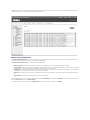
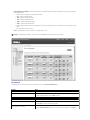
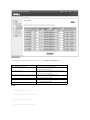
Port Configuration
On the Port Configuration page, you can view and edit port parameters. For each port number listed in the Port column, you can change the following
parameters listed by column name on the screen:
l
Name/Type — Allows a user-defined label for the port and indicates the type of port:
¡
1000Base-TX — 10/100/1000Base-T RJ-45 port
¡
1000Base-SFP — Gigabit SFP transceiver port
l
Admin/Oper — Allows the network administrator to manually disable a port and indicates the status of the link: up or down.
l
Speed/Duplex Mode — Allows the manual selection of port speed and duplex mode and indicates the current port speed and mode.
l
Flow Control — Allows automatic or manual selection of support for flow control and indicates the type of flow control currently in use.
l
l
Autonegotiation/Port Capabilities — Allows autonegotiation to be enabled/disabled and indicates the capabilities of the port that are advertised
during autonegotiation:
¡
10h — Supports 10-megabits per second (Mbps) half duplex.
¡
10f — Supports 10-Mbps full duplex.
¡
100h — Supports 100-Mbps half duplex.
¡
100f — Supports 100-Mbps full duplex.
¡
1000h — Supports 1000-Mbps half duplex.
¡
1000f — Supports 1000-Mbps full duplex.
¡
Sym — Supports symmetric operation of full-duplex flow control. The port (gigabit ports only) can transmit and receive pause frames for flow
control.
¡
FC — Supports full-duplex flow control.
Trunk — Indicates whether a port is a member of an aggregated link or trunk.
NOTICE: If autonegotiation is disabled for an RJ-45 port, the auto-MDI/MDI-X pin signal configuration is also disabled.
CLI Commands
The following table summarizes the equivalent CLI commands for items in the Ports/Port Configuration page.
Command
Usage
interface ethernet unit/port
Configures an Ethernet port interface and enters interface configuration mode.
shutdown
Disables an interface.
To restart a disabled interface, use the no form command.
description string
Adds a description to an interface.
speed-duplex {1000full | 100full | 100half | 10full |
10half}
Configures the speed and duplex mode of a given interface when autonegotiation is disabled.
negotiation
Enables autonegotiation for a given interface.
Use the no form command to disable autonegotiation.
capabilities {1000full | 100full | 100half | 10full |
10half | flowcontrol | symmetric}
Advertises the port capabilities of a given interface during autonegotiation.
Use the no form with parameters command to remove an advertised capability, or the no form
without parameters command to restore the default values.
flowcontrol
Enables flow control.
Use the no form command to disable flow control.
show interfaces status ethernet unit/port
Displays status for enabled interfaces.
show interfaces switchport [ethernet unit/port]
Displays the configuration for a port.
Example
Console(config)#interface ethernet 1/5
Console(config-if)#
Console(config-if)#description RD SW#3
Console(config-if)#no negotiation
Console(config-if)#speed-duplex 100half
Console(config-if)#flowcontrol
Trunk Configuration
On the Trunk Configuration page, you can enable and disable the aggregate port links that have been created on the switch. To set up trunks and select
port members, use the Link Aggregation page.
For each trunk number listed in the Trunk column, you can change the following parameters listed by column name on the screen:
l
Name/Type — Allows a user-defined label for the trunk and also indicates the type of ports in the trunk
l
Admin/Oper — Allows the network administrator to manually disable a trunk and also indicates the status of the link: up or down
l
Speed/Duplex Mode — Allows the manual selection of port speed and duplex mode and also indicates the current speed and mode of member ports
l
Flow Control — Allows automatic or manual selection of support for flow control and also indicates the type of flow control currently in use
l
Autonegotiation/Port Capabilities — Allows autonegotiation to be enabled/disabled for all ports in the trunk and also indicates the capabilities of the
port members
To save any changes you make in this page, click Apply Changes. If you don't want to save the changes, click Refresh.
CLI Commands
The following table summarizes the equivalent CLI commands for items in the Ports/Trunks Configuration page.
Command
Usage
interface port-channel channel-id
Configures a trunk and enters interface configuration mode.
shutdown
Disables a trunk interface.
To restart a disabled interface, use the no form command.
description string
Adds a description to a trunk interface.
speed-duplex {1000full | 100full | 100half | 10full | 10half}
Configures the speed and duplex mode of a given interface when autonegotiation
is disabled.
negotiation
Enables autonegotiation for a given interface.
To disable autonegotiation, use the no form command.
capabilities {1000full | 100full | 100half | 10full | 10half | flowcontrol |
symmetric}
Advertises the trunk capabilities of a given interface during autonegotiation.
flowcontrol
Enables flow control.
To disable flow control, use the no form command.
show interfaces status port-channel channel-id
Displays status for enabled interfaces.
show interfaces switchport [port-channel channel-id]
Displays the configuration for a trunk.
Example
Console(config)#interface port-channel 1
Console(config-if)#
Console(config-if)#description RD SW#3
Console(config-if)#no negotiation
Console(config-if)#speed-duplex 100half
Console(config-if)#flowcontrol
Broadcast Control
In the Broadcast Control page, you can enable and disable broadcast control for all ports on the switch.
The Broadcast Control page also contains the following editable fields:
l
Broadcast Control Status — Allows you to enable/disable broadcast storm control for all ports on the switch. When enabled, the switch employs a
broadcast-control mechanism if the packet-per-second threshold on a port is exceeded. (The default is enabled.)
l
Threshold (16,64,128,256) — The packet-per-second threshold for broadcast packets received on a port. Possible values are 16, 64, 128, or 256
packets per second. (The default is 256 packets per second.) If jumbo frames are enabled on the switch, the maximum threshold for broadcast storm
control is limited to 64 packets per second.
To save any changes you make in this page, click Apply Changes. If you don't want to save the changes, click Refresh.
NOTE: Broadcast control does not affect IP multicast traffic.
CLI Commands
The following table summarizes the equivalent CLI command for items in the Ports/Broadcast Control web page.
Command
Usage
switchport broadcast packet-rate rate
Configures broadcast storm control (applies to all ports)
Example
Console(config)#interface ethernet 1/5
Console(config-if)#switchport broadcast packet-rate 64
Console(config-if)#
Port Mirroring
From the Port Mirroring page, you can configure a port mirror session by setting a source and destination port pair. Port mirroring helps you debug a
network.
NOTICE: You can configure only one port mirror session on the switch.
The following options are available:
l
Sessions Table — Displays the current port mirror session
l
Source Port — Specifies the port from which all traffic will be mirrored to the destination port
l
Type — Allows you to select which traffic to mirror to the destination port: Rx, Tx, or Both
l
Destination Port — Specifies the port that receives a copy of all traffic that the source port receives or transmits
NOTE: The source port and destination port speeds must match. Otherwise traffic may be dropped from the destination port.
To add a new mirror session to the Sessions Table, first delete the current mirror session by selecting the session in the table and clicking Remove Mirror
Session. Select the new source port, destination port, and traffic type, and then click Add Mirror Session.
CLI Commands
The following table summarizes the equivalent CLI commands for items in the Ports/Port Mirroring page.
Command
Usage
port monitor interface [rx | tx | both] Configures a mirror session
show port monitor [interface]
Displays mirror information
Example
Console(config)#interface ethernet 1/6
Console(config-if)#port monitor ethernet 1/5 both
Console(config-if)#
Port Security
Port security allows you to configure a switch port with one or more device MAC addresses that are authorized to access the network through that port.
When port security is enabled on a port, the switch stops learning new MAC addresses on the specified port. Only incoming traffic with source addresses
already stored in the dynamic or static address table will be accepted as authorized to access the network through that port. If a device with an unauthorized
MAC address attempts to use the switch port, the intrusion will be detected and the switch can automatically take action by disabling the port and sending a
trap message.
To use port security, first allow the switch to dynamically learn the <source MAC address, VLAN> pair for frames received on a port for an initial period, and
then enable port security to stop address learning. Be sure you enable the learning function long enough to ensure that all valid VLAN members have been
registered on the selected port.
Note that a secure port has the following restrictions:
l
It should not be connected to a network interconnection device.
l
It cannot be configured as a member of a static trunk.
The Ports/Port Security page contains links to the following pages:
l
Global Configuration
l
Port Security Configuration
Global Configuration
On the Ports/Port Security/Global Configuration page, you can set the security action to be taken when a port intrusion is detected. This setting applies to
all ports and trunks on the switch.
The page provides one parameter to configure:
l
Shutdown and Trap — Indicates the action to be taken when a port security violation is detected:
¡
None: Indicates that no action should be taken (This is the default.)
¡
Trap and Shutdown: Indicates that the port or trunk should be disabled and an SNMP trap message sent
To save any changes you make in this page, click Apply Changes. If you don't want to save the changes, click Refresh.
Port Security Configuration
On the Ports/Port Security/Port Security Configuration page, you can enable/disable security for any switch port or trunk. For each port number listed in
the Port column, you can configure the Security Status parameter, which enables or disables port security on the port. (Default: disabled)
NOTICE: If a port is disabled due to a security violation, it must be manually re-enabled from the Ports/Port Configuration page. See the section
"Reenabling a Shutdown Port" below.
To configure port security on a trunk, check the Security Status checkbox next to the trunk number. Configured trunks are listed at the bottom of the page,
underneath the port listing.
To save any changes you make in this page, click Apply Changes. If you don't want to save the changes, click Refresh.
Reenabling a Shutdown Port
If security is enabled on a port and the intrusion action set to Trap and Shutdown, then a security violation causes the port to be disabled. To reenable a
shutdown port, follow these steps:
NOTE: To reenable a port using the CLI, use the no shutdown command in Interface Configuration mode.
1.
Open the Ports/Port Configuration page.
2.
For the port that is disabled, click the checkbox in the Admin/Oper column.
3.
Click Apply Changes to enable the port.
CLI Commands
The following table summarizes the equivalent CLI commands for items in the Ports/Port Security pages.
Command
Usage
port security
Enables port security on an interface.
Use the no form command to disable port security.
port security action {trap-and-shutdown}
Enables and configures port security on an interface.
Use the no form command to reset to defaults.
NOTICE: Although the port security action command is an interface-level CLI command, it applies globally to all switch ports.
Example
Console(config)#interface ethernet 1/5
Console(config-if)#port security action trap-and-shutdown
Console(config-if)#port security
Console(config-if)#
Address Table
The Address Table page includes links to the following pages:
l
Static Addresses
l
Dynamic Addresses
l
Address Aging
Static Addresses
From the Static Addresses page, you can specify the Media Access Control (MAC) address and port number of systems that are to remain available to the
switch for an indeterminate amount of time.
The following options are available:
l
Static Address Counts — Indicates the total number of static addresses configured on the switch
l
Current Static Address Table — Lists all static addresses
l
Interface — Allows you to select the port or trunk associated with the system you want to set as static
l
MAC Address — Allows you to enter the MAC address of a system you want to set as static
l
VLAN — Allows you to select the VLAN associated with the interface
To add a new address to the table, select the interface, MAC address, and VLAN, and then click Add Static Address. To delete an address from the table,
select the table entry in the list box, and then click Remove Static Address.
CLI Commands
The following table summarizes the equivalent CLI commands for items in the Address Table/Static Addresses page.
Command
Usage
mac-address-table static mac-address {interface interface} vlan vlan-id [action]
Maps a static address to a port in a VLAN
The action parameters are:
delete-on-reset: Assignment lasts until switch is reset
permanent: Assignment is permanent
show mac-address-table [address mac_address [mask]] [interface interface] [vlan vlan-id] [sort
{address | vlan | interface}]
Allows you to view classes of entries in the bridgeforwarding database
Example
Console(config)#mac-address-table static 00-e0-29-94-34-de ethernet 1/1 vlan 1 delete-on-reset
Console(config)#
Dynamic Addresses
The Dynamic Address lookup table allows you to view the MAC addresses that are currently in the address database. When addresses are in the database,
the packets intended for those addresses are forwarded directly to those ports. You can sort the table by interface, VLAN, and MAC address by selecting the
sort key from the drop-down menu.
The Dynamic Addresses page contains the following options for querying the dynamic MAC address table:
l
Interface — Check the option box and select a port or trunk from the drop-down menus.
l
MAC Address — Check the option box and type the address in the box provided.
l
VLAN — Check the option box and select the appropriate VLAN from the drop-down menu.
l
Address Table Sort Key — Select the key from the drop-down menu to sort the displayed table entries.
l
Query button — Click this button to execute the query once you have selected the criteria for the query.
CLI Commands
The following table summarizes the equivalent CLI commands for items in the Address Table/Dynamic Addresses page.
Command
Usage
show mac-address-table [address mac_address [mask]] [interface
interface] [vlan vlan-id] [sort {address | vlan | interface}]
Allows you to view classes of entries in the bridge-forwarding database
clear mac-address-table dynamic
Removes any learned entries from the forwarding database and clears the transmit
and receive counts for any static or system-configured entries.
Example
Console#show mac-address-table
Interface Mac Address Vlan Type --------- ----------------- ---- -------------- Eth 1/11 00-10-b5-62-03-74 1 Learned Console#
Address Aging
In the Address Aging page, you can specify the length of time an address stays available to the switch if it is not configured as static.
The Aging Time option sets the time before an address is purged from the system. You can change this value to any number between 18 and 2184. (The
default is 300 seconds.)
To save any changes you make in this page, click Apply Changes. If you don't want to save the changes, click Refresh.
CLI Commands
The following table summarizes the equivalent CLI command for items in the Address Tabled/Address Aging page.
Command
Usage
mac-address-table aging-time seconds
Sets the aging time for entries in the address table
show mac-address-table aging-time
Shows the aging time for entries in the address table.
Example
Console(config)#mac-address-table aging-time 300
Console(config)#
Spanning Tree
The Spanning Tree Protocol (STP) can be used to detect and disable network loops, and to provide backup links between switches, bridges or routers. This
allows the switch to interact with other bridging devices (i.e., an STP-compliant switch, bridge, or router) in your network to ensure that only one route exists
between any two stations on the network, and provide backup links that automatically take over when a primary link goes down.
The Spanning Tree Protocols supported by the switch include the following standards:
l
STP – Spanning Tree Protocol (IEEE 802.1D)
l
RSTP – Rapid STP (IEEE 802.1w)
RSTP is designed as a general replacement for the slower, legacy STP. RSTP achieves much faster reconfiguration (around one tenth of that required by STP)
by reducing the number of state changes before active ports start learning, predefining an alternate route that can be used when a node or port fails, and
retaining the forwarding database for ports insensitive to changes in the tree structure when reconfiguration occurs.
The Spanning Tree page contains links to pages that allow you to specify the parameters of the Spanning Tree Protocol:
l
Bridge Settings
l
Advanced Bridge Settings
l
Port Settings
l
Trunk Settings
Bridge Settings
The Bridge Settings page contains the following information:
l
Bridge ID — Identifies a unique identifier for the switch in the Spanning Tree. The ID is calculated using the defined Spanning Tree priority of the switch
and its MAC address. The lower the Bridge ID, the more likely the switch will act as the root.
l
Max Age — The maximum time (in seconds) the switch can wait without receiving a configuration message before attempting to reconfigure. All device
ports (except for designated ports) should receive configuration messages at regular intervals. If the root port ages out STP information (provided in the
last configuration message), a new root port is selected from among the device ports attached to the network. (References to "ports" in this section
means "interfaces," which includes both ports and trunks.)
l
Hello Time — Specifies the time interval (in seconds) at which the root device transmits a configuration message.
l
Forward Delay — The maximum time (in seconds) the switch will wait before changing states (i.e., discarding to learning to forwarding). This delay is
required because every device must receive information about topology changes before it starts to forward frames. In addition, each port needs time to
listen for conflicting information that would make it return to a discarding state; otherwise, temporary data loops might result.
l
Designated Root — Identifies the priority and MAC address of the device in the Spanning Tree that the switch has accepted as the root device.
l
Root Port — Specifies the port number on the switch that is closest to the root. The switch communicates with the root device through this port. If
there is no root port, the switch has been accepted as the root device of the Spanning Tree network.
l
Root Path Cost — Identifies the path cost from the root port on the switch to the root device.
l
Configuration Changes — Specifies the number of times the Spanning Tree has been reconfigured.
l
Last Topology Change — Identifies the time since the Spanning Tree was last reconfigured.
From the Bridge Settings page, under Attributes, you can configure the following Spanning Tree parameters:
l
Spanning Tree State — Enables or disables the Spanning Tree. If you enable the Spanning Tree, you must complete the other fields. (Default: enabled)
l
Spanning Tree Type — Specifies the type of STP used on the switch: (Default: RSTP)
¡
STP: Spanning Tree Protocol (IEEE 802.1D)
STP creates one Spanning Tree instance for the entire network. If multiple VLANs are implemented on a network, the path between specific VLAN
members may be inadvertently disabled to prevent network loops, thus isolating group members.
NOTICE: When the STP option is selected, the switch will use RSTP set to STP forced- compatibility mode.
l
l
l
l
¡
RSTP: Rapid Spanning Tree Protocol (IEEE 802.1w)
RSTP supports connections to either STP or RSTP nodes by monitoring the incoming protocol messages and dynamically adjusting the type of
protocol messages the RSTP node transmits, as described below:
¡
STP Mode – If the switch receives an 802.1D Bridge Protocol Data Units (BPDU) (i.e., STP BPDU) after a port's migration delay timer expires, the
switch assumes it is connected to an 802.1D bridge and starts using only 802.1D BPDUs.
¡
RSTP Mode – If RSTP is using 802.1D BPDUs on a port and receives an RSTP BPDU after the migration delay expires, RSTP restarts the migration
delay timer and begins using RSTP BPDUs on that port.
Priority — Bridge priority is used in selecting the root device, root port, and designated port. The device with the highest priority becomes the STP root
device. However, if all devices have the same priority, the device with the lowest MAC address will then become the root device.
¡
Default: 32768
¡
Range: 0-61440, in steps of 4096
¡
Options: 0, 4096, 8192, 12288, 16384, 20480, 24576, 28672, 32768, 36864, 40960, 45056, 49152, 53248, 57344, 61440
Hello Time — Interval (in seconds) at which the switch transmits a configuration message.
¡
Default: 2
¡
Minimum: 1
¡
Maximum: The lower of 10 or [(Max. Message Age / 2) -1]
Maximum Age — The maximum time (in seconds) the switch can wait without receiving a configuration message before attempting to reconfigure. All
device ports (except for designated ports) should receive configuration messages at regular intervals. Any port that ages out STP information (provided
in the last configuration message) becomes the designated port for the attached LAN. If it is a root port, a new root port is selected from among the
device ports attached to the network. (References to "ports" in this section mean "interfaces," which includes both ports and trunks.)
¡
Default: 20
¡
Minimum: The higher of 6 or [2 x (Hello Time + 1)]
¡
Maximum: The lower of 40 or [2 x (Forward Delay - 1)]
Forward Delay — The maximum time (in seconds) the switch will wait before changing states (i.e., discarding to learning to forwarding). This delay is
required because every device must receive information about topology changes before it starts to forward frames. In addition, each port needs time to
listen for conflicting information that would make it return to a discarding state; otherwise, temporary data loops might result.
¡
Default: 15
¡
Minimum: The higher of 4 or [(Max. Message Age / 2) + 1]
¡
Maximum: 30
To save any changes you make in this page, click Apply Changes. If you don't want to save the changes, click Refresh.
CLI Commands
The following table summarizes the equivalent CLI commands for items in the Spanning Tree/Bridge Settings page.
Command
Usage
spanning-tree
Enables the Spanning Tree algorithm globally for the switch.
Use the no form command to disable it.
spanning-tree mode {stp | rstp}
Selects the Spanning Tree mode for the switch.
Use the no form to return to the default (STP).
spanning-tree forward-time seconds
Configures the Spanning Tree bridge forward time globally for the switch.
spanning-tree hello-time time
Configures the Spanning Tree bridge hello time globally for the switch.
spanning-tree max-age seconds
Configures the Spanning Tree bridge maximum age globally for the switch.
spanning-tree priority priority
Configures the Spanning Tree priority globally for the switch.
show spanning-tree [interface]
Shows the Spanning Tree configuration.
Example
Console(config)#spanning-tree mode rstp
Console(config)#spanning-tree
Console(config)#spanning-tree forward-time 15
Console(config)#spanning-tree hello-time 2
Console(config)#spanning-tree max-age 20
Console(config)#spanning-tree priority 40000
Advanced Bridge Settings
From the Advanced Bridge Settings page, under Attributes, you can configure the following parameters:
l
l
Path Cost Method — The path cost is used to determine the best path between devices. The path cost method is used to determine the range of
values that can be assigned to each interface.
¡
Long: Specifies 32-bit based values that range from 1-200,000,000.
¡
Short: Specifies 16-bit based values that range from 1-65535. (This is the default.)
Transmission Limit — The maximum transmission rate for BPDUs is specified by setting the minimum interval between the transmission of consecutive
protocol messages. (Range: 1-10; Default: 3)
To save any changes you make in this page, click Apply Changes. If you don't want to save the changes, click Refresh.
CLI Commands
The following table summarizes the equivalent CLI commands for items in the Spanning Tree/Advanced Bridge Settings page.
Command
Usage
spanning-tree pathcost method {long | short} Configures the path cost method used for Rapid Spanning Tree.
Use the no form to restore the default.
spanning-tree transmission-limit count
Sets the minimum interval between the transmission of consecutive RSTP BPDUs.
Use the no form to restore the default.
Example
Console(config)#spanning-tree pathcost method long
Console(config)#spanning-tree transmission-limit 4
Console(config)#
Port and Trunk Settings
You can configure RSTP attributes for specific interfaces, including port priority, path cost, link type, and edge port. You may use a different priority or path cost
for ports of the same media type to indicate the preferred path, link type to indicate a point-to-point connection or shared-media connection, and edge port to
indicate if the attached device can support fast forwarding. (References to "ports" in this section mean "interfaces," which includes both ports and trunks.)
In the Port Settings page, you can specify Spanning Tree parameters for each port. For each port number listed in the Port column, the following information
is available:
l
State — Displays current state of this port within the Spanning Tree:
¡
Broken — No valid link on the port.
¡
Discarding — The port receives STA configuration messages, but does not forward packets.
¡
Learning— The port has transmitted configuration messages for an interval set by the Forward Delay parameter without receiving contradictory
information. The port address table is cleared, and the port begins learning addresses.
¡
Forwarding — The port forwards packets, and continues learning addresses.
l
Designated Cost — The cost for a packet to travel from this port to the root in the current Spanning Tree configuration (the slower the media, the
higher the cost)
l
Designated Bridge — The priority and MAC address of the device through which this port must communicate to reach the root of the Spanning Tree
l
Designated Port — The priority and number of the port on the designated bridging device through which this switch must communicate with the root of
the Spanning Tree
l
Trunk — Indicates whether the port is configured as a trunk member
The Port Settings page also contains the following editable fields:
l
Priority — Defines the priority used for this port in the Spanning Tree Protocol. If the path cost for all ports on a switch is the same, the port with the
highest priority (i.e., lowest value) will be configured as an active link in the Spanning Tree. This makes a port with higher priority less likely to be
blocked if the Spanning Tree Protocol is detecting network loops. Where more than one port is assigned the highest priority, the port with lowest
numeric identifier will be enabled. (Default: 128; Range: 0-240, in steps of 16)
l
Path Cost — This parameter is used by the STP to determine the best path between devices. Therefore, lower values should be assigned to ports
attached to faster media, and higher values assigned to ports with slower media. (Path cost takes precedence over port priority.)>
¡
Range:
Ethernet — 200,000-20,000,000
Fast Ethernet — 20,000-2,000,000
Gigabit Ethernet — 2,000-200,000
¡
Defaults:
Ethernet — Half duplex: 2,000,000; full duplex: 1,000,000; trunk: 500,000
Fast Ethernet — Half duplex: 200,000; full duplex: 100,000; trunk: 50,000
Gigabit Ethernet — Full duplex: 10,000; trunk: 5,000
NOTICE: When the Path Cost Method is set to short, the maximum path cost is 65,535.
l
Link Type — The link type attached to this interface. (Default: Auto)
¡
Point-to-Point — A connection to exactly one other bridge.
¡
Shared — A connection to two or more bridges.
¡
Auto — The switch automatically determines if the interface is attached to a point-to-point link or to shared media.
l
Edge Port — You can enable this option if an interface is attached to a LAN segment that is at the end of a bridged LAN or to an end node. Since end
nodes cannot cause forwarding loops, they can pass directly through to the spanning tree forwarding state. Specifying Edge Ports provides quicker
convergence for devices such as workstations or servers, retains the current forwarding database to reduce the amount of frame flooding required to
rebuild address tables during reconfiguration events, does not cause the Spanning Tree to initiate reconfiguration when the interface changes state,
and also overcomes other STP-related timeout problems. However, remember that Edge Port should only be enabled for ports connected to an endnode device.
l
Migration — Rechecks the appropriate BPDU format to send on the selected interface. If at any time the switch detects STP BPDUs, including
Configuration or Topology Change Notification BPDUs, the switch automatically sets the selected interface to forced STP-compatible mode. However, you
can also check this Migration check box to manually recheck the appropriate BPDU format (RSTP or STP-compatible) to send on the selected interfaces.
CLI Commands
The following table summarizes the equivalent CLI commands for items in the Spanning Tree/Port Settings page.
Command
Usage
spanning-tree port-priority priority
Configures the priority for the specified interface.
Use the no form to restore the default.
spanning-tree cost cost
Configures the Spanning Tree path cost for the specified interface.
Use the no form to restore the default.
spanning-tree link-type {auto | point-to-point | shared} Configures the link type for the Rapid Spanning Tree.
Use the no form to restore the default.
spanning-tree edge-port
Specifies an interface as an edge port.
Use the no form to restore the default.
spanning-tree protocol-migration interface
Rechecks the appropriate BPDU format to send on the selected interface.
Example
Console(config)#interface ethernet 1/5
Console(config-if)#spanning-tree port-priority 128
Console(config-if)#spanning-tree cost 19
Console(config-if)#spanning-tree link-type auto
Console(config-if)#no spanning-tree edge-port
Console#spanning-tree protocol-migration ethernet 1/5
VLAN
You can use virtual LANs (VLANs) to assign ports on the switch to any of up to 255 LAN groups. In conventional networks with routers, broadcast and
multicast traffic is split up into separate domains. Switches do not inherently support broadcast domains, which can lead to broadcast storms in large
networks. By using IEEE 802.1Q-compliant VLANs and GARP VLAN Registration Protocol (GVRP), you can organize any group of network nodes into separate
broadcast domains, confining broadcast and multicast traffic to the originating group. This also provides a more secure and cleaner network environment. For
more information on how to use VLANs, see "VLANs."
The VLAN page includes links to the following pages:
l
VLAN Membership
l
Port Settings
l
Trunk Settings
l
GVRP
VLAN Membership
On the VLAN Membership page, you define VLAN groups. The following options are available:
l
Show VLAN — Select the VLAN for which you want to edit the membership setting.
l
Name — Specifies user-defined name of the VLAN.
l
VLAN ID — Specifies numeric ID of the VLAN (1 to 4094).
l
Remove VLAN — Check this box to remove an existing VLAN.
l
Status — Configures the VLAN as Active or Suspended.
l
Creation — Indicates whether the VLAN has been created as a permanent (static) VLAN or has been dynamically created through GVRP.
l
Port/Trunk toggle buttons — Allows you to select VLAN membership for each port or trunk by toggling the value of the Port/Trunk button:
¡
'U': The port is a member of the VLAN. All packets transmitted by the port will be untagged, that is, not carry a tag and therefore not carry VLAN
or CoS information.
¡
'T': The port is a member of the VLAN. All packets transmitted by the port will be tagged, that is, carry a tag and, therefore, carry VLAN or CoS
information.
¡
'F': The port is forbidden from automatically joining the VLAN through GVRP. For more information, see "GVRP."
¡
'BLANK': The port is not a member of the VLAN. Packets associated with this VLAN will not be transmitted by the port.
The VLAN tagging option is a standard set by the IEEE to facilitate the spanning of VLANs across multiple switches. For more information, see "VLANs" and the
IEEE Std 802.1Q-1998 Virtual Bridged Local Area Networks.
To save any changes you make in this page, click Apply Changes. If you don't want to save the changes, click Refresh.
Adding VLAN Group
1.
Select Add a new VLAN from the Show VLAN drop-down menu.
2.
Complete the VLAN Name and VLAN ID fields.
3.
Add VLAN members.
See "VLAN Membership" for more information on VLAN members.
4.
Click Apply Changes.
Removing VLAN Group
NOTE: If you remove a VLAN group with existing port members, the ports will rejoin the default VLAN in untagged mode.
1.
Select the VLAN that you want to remove from the Show VLAN drop-down menu.
2.
Check the Remove VLAN box for the VLAN that you want to remove.
3.
Click Apply Changes.
Adding VLAN Membership
1.
Select the VLAN that you want to edit from the Show VLAN drop-down menu.
2.
Change the VLAN member by clicking the port icon until the desired state (T [tagged] or U [untagged]) or a blank appears.
3.
Click Apply Changes.
Removing VLAN Membership
1.
Select the VLAN that you want to edit under the Show VLAN drop-down menu.
2.
Change the VLAN member by clicking the port icon until the field is blank.
3.
Click Apply Changes.
CLI Commands
The following table summarizes the equivalent CLI commands for items in the VLAN/VLAN Membership page.
Command
Usage
vlan database
Allows you to enter VLAN database mode.
vlan vlan-id [name vlan-name] media ethernet
[state {suspend | active}]
Configures a VLAN.
Use the no form command to restore the default or delete a VLAN.
interface vlan vlan-id
Allows you to enter interface configuration mode for VLANs and to configure a physical interface.
switchport allowed vlan {add vlan-list [tagged |
untagged] | remove vlan-list}
Configures untagged and tagged ports.
The parameter vlan-list is the list of VLAN identifiers being added. Separate nonconsecutive VLAN identifiers
with a comma and no spaces; use a hyphen to designate a range of IDs.
switchport forbidden vlan {add vlan-list |
remove vlan-list}
Configures forbidden VLANs for a port.
show vlan [id vlan-id | name vlan-name]
Shows VLAN information.
Example
Console(config)#vlan database
Console(config-vlan)#vlan 105 name RD5 media ethernet
Console(config-vlan)#exit
Console(config)#interface ethernet 1/1
Console(config-if)#switchport allowed vlan add 105,7,9 tagged
Console(config-if)#exit
Console(config)#exit
Console#show vlan id 105
VLAN Name Status Ports/Channel groups ---- -------- --------- -------------------------------- 105 RD5 active Eth1/ 1 Eth1/ 2 Eth1/ 3 Eth1/ 4 Eth1/ 5 Eth1/ 6 Eth1/ 7 Eth1/ 8 Eth1/ 9 Eth1/10 Console#
Port Settings
On the Port Settings page, you can specify the default port VLAN ID (PVID) for each port on your switch. All untagged packets entering the switch are tagged
by default with the ID specified by the port's PVID.
The Port Settings page is set up in a table format. For each port listed in the Port column, the following options are available:
l
PVID — Specifies the VLAN ID assigned to untagged frames received on the port. (Default: 1)
NOTICE: If a port is not a member of VLAN 1 and you assign its PVID to this VLAN, the port will automatically be added to VLAN 1 as an untagged
member. For all other VLANs, a port must first be configured as an untagged member before you can assign its PVID to that group.
l
Acceptable Frame Type — Sets the port to accept all frame types, including VLAN tagged or untagged frames, or only tagged frames. When set to
receive all frame types, any received frames that are untagged are assigned to the default VLAN. (Options: ALL, Tagged; Default: ALL)
l
Ingress Filtering — If ingress filtering is enabled, incoming frames for VLANs which do not include this ingress port in their member set will be discarded
at the ingress port. (Default: Disabled)
l
Note the following points about ingress filtering:
¡
Ingress filtering only affects tagged frames.
¡
If ingress filtering is disabled, the port will accept any VLAN-tagged frame if the tag matches a VLAN known to the switch (except for those VLANs
explicitly forbidden on this port).
¡
If ingress filtering is enabled, the port will discard incoming frames tagged for VLANs which do not include this ingress port in their member set.
¡
Ingress filtering does not affect VLAN independent BPDU frames, such as GVRP or STP. However, they do affect VLAN dependent BPDU frames,
such as GMRP.
l
GVRP Status — Enables/disables GVRP for the port. GVRP defines a way for switches to exchange VLAN information to automatically register VLAN
members on ports across the network. GVRP must be globally enabled for the switch before you can individually enable GVRP for a specific port. For
more information, see "GVRP." (Default: Disabled)
l
GARP Join Timer — Specifies the interval (in centiseconds) between transmitting requests/queries to participate in a VLAN group. (The range is 20 to
1000 centiseconds.)
l
GARP Leave Timer — Specifies the interval (in centiseconds) a port waits before leaving a VLAN group. This time should be set to more than twice the
join time. This interval ensures that after a Leave or LeaveAll message has been issued, the applicants can rejoin before the port actually leaves the
group. (The range is 60 to 3000 centiseconds.)
l
GARP LeaveAll Timer — Specifies the interval (in centiseconds) between sending out a LeaveAll query message for VLAN group participants and the
port leaving the group. This interval should be considerably larger than the Leave Time to minimize the amount of traffic generated by nodes rejoining
the group. (The range is 500 to 18000 centiseconds.)
l
Mode – Indicates the VLAN membership mode for a port.
(Default: Hybrid)
¡
1Q Trunk — Specifies a port as an end point for a VLAN trunk. A trunk is a direct link between two switches, so the port transmits tagged frames
that identify the source VLAN.
¡
Hybrid — Specifies a hybrid VLAN interface. The port may transmit tagged or untagged frames.
NOTICE: If Mode is set to 1Q Trunk, frames belonging to the port's default VLAN (i.e., associated with the PVID) are sent untagged, but all other frames
are tagged with the assigned VLAN ID.
To save any changes you make in this page, click Apply Changes. If you don't want to save the changes, click Refresh.
CLI Commands
The following table summarizes the equivalent CLI commands for items in the VLAN/Port Settings page.
Command
Usage
switchport native vlan vlan-id
Configures the PVID (default VLAN ID) for a port
switchport acceptable-frame-types {all | tagged} Configures the acceptable frame types for a port
switchport ingress-filtering
Enables ingress filtering for a port
switchport gvrp
Enables GVRP for a port
garp timer {join | leave | leaveall} timer_value
Sets the values for the GVRP join, leave, and leaveall timers
show gvrp configuration [interface]
Shows whether GVRP is enabled
Example
Console(config)#interface ethernet 1/1
Console(config-if)#switchport native vlan 3
Console(config-if)#switchport acceptable-frame-types tagged
Console(config-if)#switchport ingress-filtering
Console(config-if)#
Trunk Settings
On the Trunk Settings page, you can specify the default port VLAN ID (PVID) for ports that are configured as trunk members. When an untagged packet
enters the switch, it is, by default, tagged with the ID specified by the port's PVID.
For each trunk listed in the Trunk column, the following options are available:
l
PVID — Specifies the VLAN ID assigned to untagged frames received on the trunk. (Default: 1)
NOTICE: If a trunk is not a member of VLAN 1 and you assign its PVID to this VLAN, the trunk will automatically be added to VLAN 1 as an untagged
member. For all other VLANs, a trunk must first be configured as an untagged member before you can assign its PVID to that group.
l
Acceptable Frame Type — Sets the trunk to accept all frame types, including VLAN tagged or untagged frames, or only tagged frames. When set to
receive all frame types, any received frames that are untagged are assigned to the default VLAN. (Options: ALL, Tagged; Default: ALL)
l
Ingress Filtering — If ingress filtering is enabled, incoming frames for VLANs which do not include this trunk in their member set will be discarded at the
ingress port. (Default: Disabled)
l
Note the following points about ingress filtering:
¡
Ingress filtering only affects tagged frames.
¡
If ingress filtering is disabled, the trunk will accept any VLAN-tagged frame if the tag matches a VLAN known to the switch (except for those
VLANs explicitly forbidden on this trunk).
¡
If ingress filtering is enabled, the trunk will discard incoming frames tagged for VLANs which do not include this ingress port in their member set.
¡
Ingress filtering does not affect VLAN independent BPDU frames, such as GVRP or STP. However, they do affect VLAN dependent BPDU frames,
such as GMRP.
l
GVRP Status — Enables/disables GVRP for the trunk. GVRP defines a way for switches to exchange VLAN information to automatically register VLAN
members on ports across the network. GVRP must be globally enabled for the switch before you can individually enable GVRP for a specific trunk. For
more information, see "GVRP." (Default: Disabled)
l
GARP Join Timer — Specifies the interval (in centiseconds) between transmitting requests/queries to participate in a VLAN group. (The range is 20 to
1000 centiseconds.)
l
GARP Leave Timer — Specifies the interval (in centiseconds) that a trunk waits before leaving a VLAN group. GARP Leave Timer should be set to more
than twice the join time. This interval ensures that after a Leave or LeaveAll message has been issued, the applicants can rejoin before the trunk
actually leaves the group. (The range is 60 to 3000 centiseconds.)
l
GARP LeaveAll Timer —Specifies the interval (in centiseconds) between when a LeaveAll query message for VLAN group participants is sent and when
the trunk leaves the group. This interval should be considerably larger than the Leave Time to minimize the amount of traffic generated by nodes
rejoining the group. (The range is 500 to 18000 centiseconds.)
l
Mode – Indicates the VLAN membership mode for a trunk.
(Default: Hybrid)
¡
1Q Trunk – Specifies a port as an end point for a VLAN trunk. A trunk is a direct link between two switches, so the port transmits tagged frames
that identify the source VLAN.
¡
Hybrid – Specifies a hybrid VLAN interface. The trunk may transmit tagged or untagged frames.
NOTICE: If Mode is set to 1Q Trunk, frames belonging to the trunk's default VLAN (i.e., associated with the PVID) are sent untagged, but all other
frames are tagged with the assigned VLAN ID.
To save any changes you make in this page, click Apply Changes. If you don't want to save the changes, click Refresh.
GVRP
The GVRP page allows you to globally enable GARP VLAN Registration Protocol (GVRP) for the switch. GVRP defines a way for switches to exchange VLAN
information to register VLAN members on ports across the network. You can use GVRP to set up VLANs in the network without having to manually configure
the VLANs on each switch. GVRP can reduce the possibility of errors and ensure consistency in VLAN configuration throughout the network.
If you enable GVRP on a port with a tagged or untagged static VLAN, GVRP sends advertisements (GVRP Bridge Protocol Data Units [BPDUs]) containing the
VLAN's ID. Any connected GVRP-aware port receiving the advertisements can dynamically join the advertised VLAN. All GVRP dynamically-learned VLANs
operate as tagged VLANs. A GVRP-enabled port only joins a VLAN when an advertisement for that VLAN is received on that specific port. A GVRP-enabled port
forwards advertisements from other ports on the switch but does not join the advertised VLAN.
To implement GVRP in a network, you must first configure the static VLANs required on switches that are connected to computers, servers, and other devices,
so that these VLANs can be propagated across the network. For other core switches in the network, enable GVRP on the links between these devices. You
should also determine security boundaries in the network and configure GVRP settings to limit the VLAN propagation.
When GVRP is globally enabled for the switch, the default setting allows all the ports to transmit and receive VLAN advertisements, as well as automatically
join VLANs. To control and limit the VLAN propagation in a network, you can disable GVRP on ports to prevent advertisements from being propagated, or to
forbid ports from joining specific VLANs. The VLAN Membership page allows you to set ports as Forbidden, which prevents them from joining a VLAN through
GVRP.
NOTICE: GVRP-learned VLANs on the switch do not have assigned IP addresses. Therefore, the management VLAN must be statically configured on all
switches in the network before you implement GVRP.
For more information on VLANs and GVRP see "VLANs."
NOTICE: GVRP must be globally enabled for the switch before you can individually enable GVRP for a specific port or trunk.
To save any changes you make in this page, click Apply Changes. If you don't want to save the changes, click Refresh.
CLI Commands
The following table summarizes the equivalent CLI commands for items in the VLAN/GVRP page.
Command
Usage
bridge-ext gvrp
Enables GVRP for the switch.
Use the no form command to disable it.
show gvrp configuration [interface] Shows whether GVRP is enabled.
Example
Console(config)#bridge-ext gvrp
Console(config)#
Class of Service
Class of Service (CoS) allows you to assign priority to data packets when traffic in the switch is buffered due to congestion. This switch supports CoS by using
four priority queues for each port. Data packets in a port's high-priority queue will be transmitted before packets in the lower-priority queues.
The Class of Service page allows you to set the default priority for each port or trunk, and to configure the mapping of frame priority tags to the switch's four
priority queues. The page includes links to the following options:
l
Port Settings — Sets the default priority for each port
l
Trunk Settings — Sets the default priority for each trunk
l
Traffic Classes — Configures the mapping of IEEE 802.1p priority tags to the switch's four traffic class queues
l
Queue Scheduling — Configures Weighted Round Robin (WRR) queueing for the switch ports
l
Layer 3/4 Priority — Configures the mapping of IP Precedence/DSCP values or IP TCP/UDP port numbers to the switch's four priority queues
NOTICE: The IEEE 802.1p tags specify eight levels of priority, from the lowest (0) to the highest (7). IP Precedence or IP DSCP values are mapped to
these priority tag levels, and the priority levels are mapped directly to the switch's four traffic class queues.
Port Settings
In the Port Settings page, you can specify the default port priority for each port on the switch. All packets entering the switch that are untagged (do not
already have a priority value) are tagged with the specified default port priority and then sorted into the appropriate priority queue at the output port.
For each port listed in the Port column, you can assign the default port priority (from 0 to 7) to untagged frames received on the port. The default setting for
ports is 0.
CLI Commands
The following table summarizes the equivalent CLI command for items in the Class of Service/Port Settings page.
Command
Usage
switchport priority default defaultpriority-id
Sets a priority for the incoming untagged frames or the priority of frames received by the device connected to the
specified interface
Example
Console(config)#interface ethernet 1/3
Console (config-if)#switchport priority default 5
Trunk Settings
On the Trunk Settings page, you can specify the default port priority for each port in a switch trunk. All packets entering the switch that are untagged (do not
already have a priority value) are tagged with the specified default port priority and then sorted into the appropriate priority queue at the output port.
For each trunk listed in the Trunk column, you can assign the default port priority (from 0 to 7) to untagged frames received on any port in the trunk. The
default setting is 0.
CLI Commands
The following table summarizes the equivalent CLI command for items in the Class of Service/Trunk Settings page.
Command
Usage
switchport priority default defaultpriority-id
Sets a priority for the incoming untagged frames or the priority of frames received by the device connected to the
specified interface
Example
Console(config)#interface port-channel 2
Console (config-if)#switchport priority default 5
Traffic Classes
On the Traffic Classes page, you can configure the mapping of frame priority tags to each port's four CoS priority queues.
Each IEEE 802.1p priority level (from 0 to 7) listed in the Priority column can be mapped to one of the switch's four traffic class queues (from 0 to 3). The
number 0 represents a low priority and higher values represent higher priorities.
CLI Commands
The following table summarizes the equivalent CLI commands for items in the Class of Service/Traffic Classes page.
Command
Usage
queue cos-map queue_id [cos1 ... cosn] Assigns traffic class values to the CoS priority queues.
Use the no form command to set the CoS map to the default values.
show queue cos-map [interface]
Shows the CoS priority map.
Example
Console(config)#queue cos-map 0 0 1 2
Console(config)#queue cos-map 1 3
Console(config)#queue cos-map 2 4 5
Console(config)#queue cos-map 3 6 7
Console#show queue cos-map
Information of Eth 1/1
Queue ID Traffic class -------- ------------ 0 0 1 2 1 3 2 4 5 3 6 7 .
.
.
Queue Scheduling
In the Queue Scheduling page, you can configure Weighted Round Robin (WRR) queueing for the switch ports.
The following options are available:
l
WRR Setting Table — Displays a list of weight values for each switch CoS queue
l
Weight Value — Sets a new weight value for a CoS
To change a table setting, select the entry in the WRR Setting Table, type the new weight in the Weight Value box, and then click Apply Changes. If you
don't want to save the changes, click Refresh.
CLI Commands
The following table summarizes the equivalent CLI commands for items in the Class of Service/Queue Scheduling page.
Command
Usage
queue bandwidth weight1...weight4
Assigns WRR weights to the four CoS priority queues.
Use the no form command to restore the default weights.
show queue bandwidth
Displays the WRR bandwidth allocation for the four CoS priority queues.
Example
Console(config)#queue bandwidth 1 4 16 64
Console(config)#exit
Console#show queue bandwidth
Queue ID Weight
-------- ----- 0 1 1 4 2 16 3 64 Console#
Layer 3/4 Priority
You can assign Layer 3/4 priority to traffic in the switch by considering the settings in the Type of Service (ToS) field in the IP header of a frame. The ToS field
may contain three bits for IP Precedence or six bits for Differentiated Services Code Point (DSCP) value, depending on whether you have DSCP or IP
Precedence-aware devices in your network. You can use the Layer 3/4 Priority page to identify IP traffic priorities and map the priorities to the CoS values in
the priority tag of each frame.
The following figure shows the ToS field structure for IP Precedence and IP DSCP.
NOTE: The switch allows you to choose between IP Precedence or DSCP priority. Select one of the methods or disable this feature.
IP Precedence
From the IP Precedence section, you can map IP Precedence values to traffic class values. These settings apply to all ports on the switch.
The following options are available:
l
IP Precedence Priority Table — Displays a list of IP Precedence values with mapped CoS values.
l
Class of Service Value — Maps a CoS value to an IP Precedence value. The number 0 represents low priority and 7 represents high priority.
Click IP Precedence in the IP Precedence/DSCP Priority Status field to enable this feature.
Each IP Precedence value (from 0 to 7) is mapped to one CoS value (from 0 to 7). The number 0 represents the lowest priority and 7 represents the highest
priority.
The following table shows the default priority mapping.
IP Precedence
Value
CoS
Value
0
0
1
1
2
2
3
3
4
4
5
5
6
6
7
7
To change a table setting, click the entry in the IP Precedence Priority Table, type the new CoS value in the Class of Service Value box, and then click
Apply Changes. If you don't want to save the changes, click Refresh.
DSCP Priority
The DSCP value is six bits wide, allowing coding for up to 64 different forwarding behaviors. The DSCP value replaces the ToS bits, and it retains backward
compatibility with the three precedence bits so that non-DSCP compliant, ToS-enabled devices, will not conflict with the DSCP mapping. Based on network
policies, different kinds of traffic can be marked for different kinds of forwarding.
In the IP DSCP Priority section, you can map DSCP values to traffic class values. These settings apply to all ports on the switch.
The following options are available:
l
DSCP Priority Table — Displays a list of DSCP values mapped to CoS values.
l
Class of Service Value — Sets a new CoS for a DSCP value. The number 0 represents low priority and 7 represents high priority.
Click IP DSCP in the IP Precedence/DSCP Priority Status field to enable this feature.
Each IP DSCP value (from 0 to 63) is mapped to one CoS value (from 0 to 7). The number 0 represents the lowest priority and 7 represents the highest priority.
The following table shows the default priority mapping. All of the DSCP values that are not specified are mapped to CoS value 0.
IP DSCP Value
CoS
Value
0
0
8
1
10, 12, 14, 16
2
18, 20, 22, 24
3
26, 28, 30, 32, 34, 4
36
38, 40, 42
5
48
6
46, 56
7
To change a table setting, select the entry in the DSCP Priority Table, type the new CoS value in the Class of Service Value box, and then click Apply
Changes. If you don't want to save the changes, click Refresh.
CLI Commands
The following table summarizes the equivalent CLI commands for items in the Class of Service/IP Precedence web page.
Command
Usage
map ip precedence
Enables IP precedence mapping (IP ToS) for the switch
map ip precedence ip-precedence-value cos cos-value
Sets IP precedence priority (IP ToS priority) for a port or trunk interface (applies to all ports)
show map ip precedence [interface]
Shows the IP precedence priority map
map ip dscp
Enables IP DSCP mapping for the switch
map ip dscp dscp-value cos cos-value
Sets IP DSCP priority for a port or trunk interface (applies to all ports)
show map ip dscp [interface]
Shows the IP DSCP priority map
Example
Console(config)#map ip precedence
Console(config)#interface ethernet 1/5
Console(config-if)#map ip precedence 1 cos 1
Console(config-if)#exit
Console(config)#map ip dscp
Console(config)#interface ethernet 1/5
Console(config-if)#map ip dscp 1 cos 0
Console(config-if)#exit
Console(config)#exit
Console#show map ip dscp ethernet 1/1
DSCP mapping status: disabled
Port DSCP COS --------- ---- -- Eth 1/ 1 0 0 Eth 1/ 1 1 0 Eth 1/ 1 2 0 Eth 1/ 1 3 0 .
.
.
Eth 1/ 1 61 0 Eth 1/ 1 62 0 Eth 1/ 1 63 0 Console(config)#
Link Aggregation
From the Link Aggregation page, you can create multiple links between switches that work as one virtual, aggregate link. You can create up to six trunks at a
time, with each trunk containing up to four ports. A port trunk offers a dramatic increase in bandwidth for network segments where bottlenecks exist and
provides a fault-tolerant link between two devices.
The switch supports two types of link aggregation—static and Link Aggregation Control Protocol (LACP).
LACP-configured ports automatically negotiate a trunked link with LACP-configured ports on another device. You can configure any number of ports on the
switch as LACP, as long as they are not already configured as part of another trunk. If ports on another device are also configured as LACP, the switch and
the other device negotiate a trunk link between them. If an LACP trunk consists of four ports, all other ports are placed in a standby mode. If one link in the
trunk fails, one of the standby ports is automatically activated to replace it.
Use the following guidelines when you configure port trunks:
l
Finish configuring port trunks before you connect the corresponding network cables between switches.
l
You can configure up to six trunk groups, with up to four ports as a trunk group.
l
All ports in the same trunk must consist of the same media type (for example, twisted-pair or fiber).
l
The ports on both ends of the trunk must be configured for the same VLAN, speed, duplex mode, flow control, and CoS settings.
l
If the target switch has also enabled LACP on the connected ports, the trunk will automatically activate.
l
If more than four ports attached to the same target switch have LACP enabled, the additional ports enter standby mode and will only be enabled if one
of the active links fails.
l
STP, VLAN, and IGMP settings can only be made for the entire trunk through the specified port-channel.
To add a port to a static trunk, click the Static toggle button below the port number until the correct trunk number appears. To make a port available for an
LACP trunk, click the LACP toggle button below the port number until an L appears.
NOTICE: All ports on both ends of an LACP trunk must be configured for full duplex, either by forced mode or autonegotiation.
NOTICE: All ports participating in a trunk should have the same VLAN and CoS settings.
NOTICE: In order for a port to join an existing trunk through LACP, the port's Flow Control, Speed and Duplex Mode, and Autonegotiation settings must
match those of the existing trunk.
To save any changes you make in this page, click Apply Changes. If you don't want to save the changes, click Refresh.
CLI Commands
The following table summarizes the equivalent CLI commands for items in the Link Aggregation/Trunk Settings page.
Command
Usage
channel-group channel-id
Adds a port to a trunk.
Use the no form command to remove a port from a trunk.
lacp
Enables 802.3ad LACP for the current port or trunk interface.
show interfaces status port-channel channel-id
Displays the status of an enabled trunk interface.
Example
Console(config)#interface port-channel 1
Console(config-if)#exit
Console(config)#interface ethernet 1/11
Console(config-if)#channel-group 1
Console(config-if)#exit
Console(config)#interface ethernet 1/8
Console(config-if)#lacp
Console(config-if)#
SNMP
The SNMP page contains links to the following pages:
l
Communities
l
Traps
l
IP Filtering
Communities
On the Communities page, you can create different communities and customize access. The public string has read-only privileges by default.
The following options are available:
l
SNMP Community Capability — Indicates that the switch supports up to five community strings.
l
Community List — Displays a list of the community strings currently configured. Default strings are public (read-only access) and private (read/write
access).
l
Community String — Allows you to name a new community. Community strings are case sensitive.
l
Access Mode — Sets the access rights for the new community that you are creating. Access rights are either read-only or read/write.
To add an SNMP community, type the new name in the Community String box, select the access rights from the Access Mode drop-down menu, and then click
Add Community String. To delete a community, click the entry in the Community List, and then click Remove Community String.
CLI Commands
The following table summarizes the equivalent CLI command for items in the SNMP/Communities page.
Command
Usage
snmp-server community string
[ro|rw]
Defines the community access string for the Simple Network Management Protocol. Read-only access is specified by ro, and
read-write access is specified by rw.
Example
Console(config)#snmp-server community private rw
Console(config)#
Traps
On the Traps page, you can specify management stations that receive authentication failure messages and other trap messages from the switch.
NOTICE: The switch does not prevent IP addresses that are not in the Trap Manager list from accessing the switch through SNMP. You only need a
valid community string for access.
The following options are available:
l
Trap Manager Capability — Indicates that the switch supports up to five trap managers
l
Trap Manager List — Displays a list of the trap managers currently configured
l
IP address — Specifies the IP address of a new management station to receive trap messages
l
Community String — Identifies the community string for the new trap manager you are creating
To add a trap manager, type the new IP address in the IP Address box, type the appropriate SNMP community in the Community String box, and then click
Add Trap Manager. To delete a trap manager, click the entry in the Trap Manager List, and then click Remove Trap Manager.
CLI Commands
The following table summarizes the equivalent CLI commands for items in the SNMP/Traps page.
Command
Usage
snmp-server host host-addr community-string
Specifies the recipient of an SNMP notification operation
snmp-server enable traps [authentication | link-up-down] Enables the device to send SNMP traps
Example
Console(config)#snmp-server host 10.1.19.23
Console(config)#snmp-server enable traps link-up-down
Console(config)#
IP Filtering
On the SNMP/IP Filtering page, you can create a list of up to 16 IP addresses or IP address groups that are allowed access to the switch via SNMP
management software.
IP addresses that are permitted SNMP access are specified by an IP address together with a subnet mask that identifies the range of valid addresses. For
example:
IP address 192.168.1.1 and mask 255.255.255.0 — Specifies a valid IP address group from 192.168.1.0 to 192.168.1.255
IP address 192.168.1.1 and mask 255.255.255.255 — Specifies a valid IP address of 192.168.1.1 only
NOTE: IP filtering does not affect management access to the switch using the Web interface or Telnet.
The following options are available:
l
IP Filter List — Displays a list of the IP address/subnet mask entries currently configured for SNMP access.
l
IP address — Specifies a new IP address to add to the IP Filter List.
l
Subnet Mask — Specifies a single IP address or group of addresses. If the IP is the address of a single management station, the mask should be set to
255.255.255.255. Otherwise, the IP address group is specified by the mask.
NOTICE: The default setting is null, which allows all IP groups SNMP access to the switch. If one IP address is configured, the IP filtering is enabled and
only addresses in the IP group will have SNMP access.
To add an IP address, type the new IP address in the IP Address box, type the appropriate subnet mask in the Subnet Mask box, and then click Add IP
Filtering Entry. To delete an IP address, click the entry in the IP Filter List, and then click Remove IP Filtering Entry.
CLI Commands
The following table summarizes the equivalent CLI command for items in the SNMP/IP Filtering page.
Command
Usage
snmp ip filter ip_address subnet_mask Sets IP addresses of clients allowed to management access to the switch via SNMP.
Use the no form of this command to remove an IP address.
Example
Console(config)#snmp ip filter 10.1.2.3 255.255.255.255
Console(config)#
Multicast Support
Multicasting is used to support real-time programs such as video conferencing or streaming audio. A multicast server does not have to establish a separate
connection with each client. Instead, it broadcasts its service to the network and to any hosts that are supposed to receive the multicast register with their
local multicast routers/switches. This approach reduces the network overhead required by a multicast server. However, each time the broadcast traffic passes
through a multicast router/switch, the traffic must be carefully queried to ensure that only hosts that subscribe to the service receive the broadcast.
The switch uses the Internet Group Management Protocol (IGMP) to determine if any attached hosts are supposed to receive a specific IP multicast service.
IGMP runs between hosts and their adjacent multicast routers/switches. IGMP is a multicast host registration protocol that allows any host to inform its local
router that the host is supposed to receive transmissions addressed to a specific multicast group.
IGMP requires one device to act as the querier on each LAN subnetwork. The querier is the IGMP-enabled device that periodically sends query messages to all
hosts asking them if they want to receive multicast traffic. Hosts respond with report messages, indicating to multicast groups that they wish to join or to
which group they already belong. The querier then propagates the service requests on to any adjacent multicast switch/router to ensure that it continues to
receive the multicast services.
IGMP-enabled devices prune multicast traffic on the network by passively snooping on IGMP report messages passing through their ports. The devices monitor
host report messages, pick out the multicast group registration information, and then configure filters accordingly so that multicast traffic for particular groups
is not forwarded on to ports that do not require it. This capability significantly reduces the multicast traffic on the network.
The Multicast Support page contains links to the following pages:
l
IGMP Setting
l
IGMP Member Port Table
l
Multicast Router Port Settings
IGMP Setting
With IGMP Snooping, you can configure the switch to forward multicast traffic intelligently. Based on the IGMP query and report messages, the switch
forwards traffic only to the ports that request multicast traffic. This querying prevents the switch from broadcasting the traffic to all ports and possibly
disrupting network performance.
NOTE: IGMP requires a router that learns about the presence of multicast groups on its subnets and keeps track of group membership.
On the IGMP Setting page, the following options are available:
l
IGMP Status — Enables IGMP. When IGMP is enabled, the switch monitors network traffic to determine which hosts are supposed to receive multicast
traffic.
l
Act as IGMP Querier — Enables the switch as Querier. When Querier is enabled, the switch can serve as the Querier, which is responsible for asking
hosts if they are supposed to receive multicast traffic.
l
IGMP Query Count (2–10) — Sets the maximum number of queries issued for which there has been no response before the switch takes action to
solicit reports. (The range is 2 to 10.)
l
IGMP Query Interval (60–125) — Sets the frequency at which the switch sends IGMP host-query messages. (The range is 60 to 125.)
l
IGMP Report Delay (5–30) — Sets the time (in seconds) between receiving an IGMP Report for an IP multicast address on a port before the switch
sends an IGMP Query out of that port and removes the entry from its list. (The range is 5 to 30.)
l
IGMP Query Timeout (300–500) — Sets the time the switch waits after the previous querier has stopped querying before it takes over as the
querier. (The range is 300 to 500.)
l
IGMP Version — Sets the protocol version for compatibility with other devices on the network (1 or 2).
To save any changes you make in this page, click Apply Changes. If you don't want to save the changes, click Refresh.
CLI Commands
The following table summarizes the equivalent CLI commands for items in the Multicast Support/IGMP Setting page.
Command
Usage
ip igmp snooping
Enables IGMP snooping on the switch
ip igmp snooping querier
Enables the switch as an IGMP snooping querier
ip igmp snooping query-count count
Configures the query count
ip igmp snooping query-interval seconds
Configures the snooping query interval
ip igmp snooping query-max-response time seconds
Configures the snooping report delay
ip igmp snooping query-time-out seconds
Configures the snooping query-timeout
ip igmp snooping version {1 | 2}
Configures the IGMP snooping version
show ip igmp snooping
Shows the IGMP snooping configuration
Example
Console(config)#ip igmp snooping
Console(config)#ip igmp snooping querier
Console(config)#ip igmp snooping query-count 10
Console(config)#ip igmp snooping query-interval 100
Console(config)#ip igmp snooping query-max-response-time 20
Console(config)#ip igmp snooping query-time-out 300
Console(config)#ip igmp snooping version 1
Console(config)#exit
Console#show ip igmp snooping
Service status: Enabled Querier status: Enabled Query count: 10 Query interval: 100 sec Query max response time: 20 sec Router port expire time: 300 sec IGMP snooping version: Version 1 Console#
IGMP Member Port Table
You can use the IGMP Member Port Table page to assign ports that are attached to hosts that are supposed to receive a specific multicast service.
The following options are available:
l
VLAN ID — Specifies the VLAN ID
l
Multicast IP Address — Allows you to select or add the IP address for a specific multicast service
l
New IP Address — Specifies the IP address of a new multicast service
l
Port/Trunk Toggle Buttons — Allows you to select ports or trunks to receive the specified multicast service by toggling the value of the port/trunk
button:
¡
'S' — Statically sets a port or trunk as a group member of the multicast service
¡
'D' — Indicates that a port or trunk has been dynamically set as a group member of the multicast service
¡
'BLANK' — Indicates that the port or trunk is not a group member of the multicast service
NOTICE: You must set at least one port or trunk as a static member before you add a new multicast IP address. If you remove all static members from
a group, the IP address is also removed.
To save any changes you make in this page, click Apply Changes. If you don't want to save the changes, click Refresh.
CLI Commands
The following tables summarize the equivalent CLI commands for items in the Multicast Support/IGMP Member Port Table page.
Command
Usage
ip igmp snooping vlan vlan-id static ip-address interface
Adds a port to a multicast group
show mac-address-table multicast [vlan vlan-id] [user | igmp-snooping] Shows the multicast list with MAC and IP addresses
Example
Console(config)#ip igmp snooping vlan 1 static 224.1.2.3 ethernet 1/11
Console(config)#exit
Console#show mac-address-table multicast
VLAN M'cast IP addr. Member ports Type
---- --------------- ------------ ------ 1 224.1.2.3 Eth 1/11 User Console#
Multicast Router Port Settings
You can use the Multicast Router Port Settings page to display or set ports on the switch that are attached to a neighboring multicast router/switch for each
VLAN ID.
The following options are available:
l
VLAN ID — Specifies the VLAN ID
l
Port/Trunk Toggle Buttons — Allows you to select ports or trunks that are attached to a neighboring multicast router/switch by toggling the value of
the port/trunk button:
¡
'S' — Statically attaches a port or trunk to a multicast router/switch
¡
'D' — Indicates that a port or trunk has been dynamically attached to a multicast router/switch
¡
'BLANK' — Indicates that the port or trunk is not attached to a multicast router/switch
To save any changes you make in this page, click Apply Changes. If you don't want to save the changes, click Refresh.
CLI Commands
The following table summarizes the equivalent CLI commands for items in the Multicast Support/Multicast Router Port Settings page.
Command
Usage
ip igmp snooping vlan vlan-id mrouter interface
Statically configures a multicast router port
show ip igmp snooping mrouter [vlan vlan-id]
Displays information on statically configured and dynamically learned multicast router ports
Example
Console(config)#ip igmp snooping vlan 1 mrouter ethernet 1/5
Console(config)#exit
Console#show ip igmp snooping mrouter vlan 1
VLAN M'cast Router Port Type
---- ------------------ ------ 1 Eth 1/ 5 Static Console#
Statistics
From the Statistics page, you can chart a variety of system data. You can see the value of each bar or line in the chart by clicking the bar. For each chart,
after you have set all the variables, click Draw.
NOTE: Rates are displayed as counts per second. Counters are cumulative from the last time the system was booted.
The Statistics page contains links to the following pages:
l
Chart
l
Table
l
Utilization Summary
l
Counter Summary
Chart
The Chart page compares one type of statistic across all ports or trunks. You must define the following variables:
l
Statistics — Specifies the type of system data to monitor
l
Refresh Rate — Specifies the time interval between automatic refreshes
Table
The Table page lists, in table format, all statistics counters for a specific port or trunk. You must specify the port or trunk from the drop-down menus, and then
click Query.
You can clear a port's counters by clicking the Reset Counter button at the bottom of the Table page.
CLI Commands
The following table summarizes the equivalent CLI commands for items in the Statistics/Table page.
Command
Usage
show interfaces counters interface
Statically configures a multicast router port
clear counters interface
Clears statistics on an interface
Example
Console#show interfaces counters ethernet 1/12
Ethernet 1/12
Iftable stats: Octets input: 91248, Octets output: 343887 Unitcast input: 680, Unitcast output: 593 Discard input: 0, Discard output: 0 Error input: 0, Error output: 0 Unknown protos input: 0, QLen output: 0 Extended iftable stats: Multi-cast input: 0, Multi-cast output: 1854
Broadcast input: 138, Broadcast output: 165 Ether-like stats:
Alignment errors: 0, FCS errors: 0 Single Collision frames: 0, Multiple collision frames: 0 SQE Test errors: 0, Deferred transmissions: 0 Late collisions: 0, Excessive collisions: 0 Internal mac transmit errors: 0, Internal mac receive errors: 0 Frame too longs: 0, Carrier sense errors: 0 RMON stats: Drop events: 0, Octets: 435135, Packets: 3430 Broadcast pkts: 303, Multi-cast pkts: 1854
Undersize pkts: 0, Oversize pkts: 0 Fragments: 0, Jabbers: 0 CRC align errors: 0, Collisions: 997976404 Packet size <= 64 octets: 2584, Packet size 65 to 127 octets: 211 Packet size 128 to 255 octets: 198, Packet size 256 to 511 octets: 317 Packet size 512 to 1023 octets: 95, Packet size 1024 to 1518 octets: 25 Console#
Console#configure
Console(config)#clear counters ethernet 1/12
Utilization Summary
The Statistics/Utilization Summary page provides a per-port summary of traffic types and bandwidth utilization as a percentage of total traffic.
This page displays the following information for each port:
l
%Port Utilization — The percentage of bandwidth used by all traffic types on the port
l
%Unicast Received — The percentage of traffic received on the port that consists of unicast packets
l
%Multicast Packets Received — The percentage of traffic received on the port that consists of multicast packets
l
%Broadcast Packets Received — The percentage of traffic received on the port that consists of broadcast packets
l
%Error Packets Received — The percentage of traffic received on the port that consists of packets with errors
Counter Summary
The Statistics/Counter Summary page provides a per-port summary of traffic-type counters.
NOTE: Counters are cumulative from the last time the system was booted.
This page displays the following information:
l
Received Unicast Packets — Total number of unicast packets received on the port
l
Transmit Unicast Packets — Total number of unicast packets transmitted on the port
l
Received Multicast Packets — Total number of multicast packets received on the port
l
Transmit Multicast Packets — Total number of multicast packets transmitted on the port
l
Received Broadcast Packets — Total number of broadcast packets received on the port
l
Transmit Broadcast Packets — Total number of broadcast packets transmitted on the port
l
Received Errors — Total number of error packets received on the port
l
Transmit Errors — Total number of error packets transmitted on the port
CLI Commands
The following table summarizes the equivalent CLI commands for items in the Statistics/Counter Summary page.
Command
Usage
show interfaces counters interface
Displays statistics counters for an interface.
clear counters interface
Clears statistics counters on an interface.
NOTE: You can also clear a port's counters by clicking the Reset Counter button at the bottom of the Statistics/Table page.
Example
Console#show interfaces counters ethernet 1/17
Ethernet 1/17
Iftable stats: Octets input: 91248, Octets output: 343887 Unitcast input: 680, Unitcast output: 593 Discard input: 0, Discard output: 0 Error input: 0, Error output: 0 Unknown protos input: 0, QLen output: 0 Extended iftable stats: Multi-cast input: 0, Multi-cast output: 1854
Broadcast input: 138, Broadcast output: 165 Ether-like stats:
Alignment errors: 0, FCS errors: 0 Single Collision frames: 0, Multiple collision frames: 0 SQE Test errors: 0, Deferred transmissions: 0 Late collisions: 0, Excessive collisions: 0 Internal mac transmit errors: 0, Internal mac receive errors: 0 Frame too longs: 0, Carrier sense errors: 0 RMON stats: Drop events: 0, Octets: 435135, Packets: 3430 Broadcast pkts: 303, Multi-cast pkts: 1854
Undersize pkts: 0, Oversize pkts: 0 Fragments: 0, Jabbers: 0 CRC align errors: 0, Collisions: 997976404 Packet size <= 64 octets: 2584, Packet size 65 to 127 octets: 211 Packet size 128 to 255 octets: 198, Packet size 256 to 511 octets: 317 Packet size 512 to 1023 octets: 95, Packet size 1024 to 1518 octets: 25 Console#
Console#configure
Console(config)#clear counters ethernet 1/17
Back to Contents Page
Back to Contents Page
VLANs
Dell™ PowerConnect™ 5212 Systems User's Guide
VLANs and Frame Tagging
VLAN Configuration
Automatic VLAN Registration
VLAN Examples
VLANs and Frame Tagging
The PowerConnect 5212 switch supports IEEE 802.1Q-compliant virtual LANs (VLANs). This capability provides a highly efficient architecture for establishing
VLANs within a network and for controlling broadcast/ multicast traffic between workgroups. Central to this capability is an explicit frame tagging approach for
carrying VLAN information between interconnected network devices.
With frame tagging, a four-byte data tag field is attached to frames that cross the network. The tag identifies to which VLAN the frame belongs. The tag may
be added to the frame by the end station itself or by a network device, such as a switch. In addition to VLAN information, the relative priority of the frame in
the network can be specified by the tag.
VLANs provide greater network efficiency by reducing broadcast traffic, and they also allow you to make network changes without having to update IP
addresses or IP subnets. VLANs inherently provide a high level of network security, since traffic must pass through a Layer 3 switch or a router to reach a
different VLAN.
The PowerConnect 5212 switch supports the following VLAN features:
l
Up to 255 VLANs based on the IEEE 802.1Q standard
l
Distributed VLAN learning across multiple switches using explicit or implicit tagging and GVRP (GARP VLAN Registration Protocol)
l
Port overlapping, allowing a port to participate in multiple VLANs
l
End stations that can belong to multiple VLANs
l
Passing traffic between VLAN-aware and VLAN-unaware devices
l
Four-level priority tagging
l
Link aggregation with VLANs
VLAN Configuration
By default, VLAN operation on the switch is enabled. Therefore, all frames are transferred internally through the switch with a VLAN tag. This tag may already
be on the frame entering the switch, or added to the frame by the switch. VLAN information already existing on frames entering the switch is automatically
handled by the switch. The switch learns VLAN information from tagged frames and appropriately switches frames out the proper ports based on this
information. The configuration of VLANs for frames entering the switch without tags must be made by the user of the switch. This configuration can be made
either through the web or console interface, or through Simple Network Management Protocol (SNMP).
Assigning Ports to VLANs
Before enabling VLANs for the switch, you must first assign each port to the VLAN groups in which it will participate. By default, all ports are assigned to VLAN
1 as untagged ports. You should add a tagged port (a port attached to a VLAN-aware device) if you want it to carry traffic for one or more VLANs and the
device at the other end of the link also supports VLANs. Assign the port at the other end of the link to the same VLANs. However, if you want a port on this
switch to participate in one or more VLANs and the device at the other end of the link does not support VLANs, you must add an untagged port (a port
attached to a VLAN-unaware device).
Port-based VLANs are tied to specific ports. The switch's forwarding determination is based on the destination MAC address and its associated port.
Therefore, to make valid forwarding and flooding decisions, the switch learns the relationship of the MAC address to its related port (and to the VLAN) at runtime.
VLAN Classification
Packets that the switch receives are treated in the following ways:
l
When an untagged packet enters a port, the system automatically tags it with the port's default VLAN ID tag number. Each port has a default VLAN ID
setting that is user configurable. The default setting is 1. You can change the default VLAN ID setting for each port from the VLAN Port Settings page.
l
When a tagged packet enters a port, the default VLAN ID setting has no effect on the tag.
¡
The packet proceeds to the VLAN specified by its VLAN ID tag number.
¡
If the port in which the packet entered does not belong to the VLAN specified by the packet's VLAN ID tag, the system drops the packet.
NOTE: You can change port VLAN membership settings in the VLAN Membership page.
¡
l
If the port belongs to the VLAN specified by the packet's VLAN ID, the system can send the packet to other ports with the same VLAN ID.
Packets leaving the switch are either tagged or untagged depending on that port's membership properties.
l
In the VLAN Membership page, if a U is assigned to a port and VLAN, packets leaving the switch from that port and VLAN are untagged. If a T is
assigned to a port and VLAN, packets leaving the switch from that port and VLAN are tagged with the respective ID for the VLAN to which that port
belongs.
Port Overlapping
Port overlapping can be used to allow access to commonly shared network resources among different VLAN groups, such as file servers or printers. If you
implement VLANs that do not overlap but still need to communicate, you must connect them using a router or Layer 3 switch.
Forwarding Tagged/Untagged Frames
Ports can be assigned to multiple tagged or untagged VLANs. Each port on the switch is, therefore, capable of passing tagged or untagged frames. To
forward a frame from a VLAN-aware device to a VLAN-unaware device, the switch first determines where to forward the frame. The switch then strips off the
VLAN tag. However, to forward a frame from a VLAN-unaware device to a VLAN-aware device, the switch first determines where to forward the frame. It then
inserts a VLAN tag reflecting this port's default VID. The default port VLAN ID is 1, but it can be changed from the VLAN Port Settings page.
Automatic VLAN Registration
GARP VLAN Registration Protocol (GVRP) defines a way for switches to exchange VLAN information to automatically register VLAN members on ports across the
network.
GVRP uses GVRP Bridge Protocol Data Units (GVRP BPDUs) to advertise static VLANs to other switches in the network. Any GVRP-enabled device receiving the
advertisements can dynamically join the advertised VLAN. All GVRP-dynamically learned VLANs operate as tagged VLANs. A GVRP-enabled port only joins a
VLAN when an advertisement for that VLAN is received on that specific port. A GVRP-enabled port forwards advertisements from other ports on the switch but
does not join the advertised VLAN.
Hosts, such as computers and servers, can be connected to switch ports that are part of a statically configured VLAN. If GVRP is enabled on the switch, these
VLANs are advertised to the rest of the network. If a host (or its network adapter) supports GVRP, it can directly indicate the VLAN groups that it is supposed
to join. When the attached GVRP-enabled switch receives the VLAN advertisements, it automatically places the receiving port in the specified VLANs and then
forwards the advertisements to all other ports. When the advertisements arrive at another GVRP-enabled switch, the switch places the receiving port in the
specified VLANs, and passes the advertisements on to all other ports. As a result, VLAN requirements are spread throughout the network, which allows GVRPcompliant devices to be automatically configured for VLAN groups based solely on host requests.
The following figure shows how GVRP can propagate VLANs across a network.
VLAN Examples
The following two examples demonstrate typical web-interface VLAN configurations for the switch.
l
Example 1 demonstrates a simple two-group VLAN setup.
l
Example 2 demonstrates a more elaborate setup, illustrating all possible scenarios for a comprehensive understanding of tagged VLANs.
Example 1
Example 1 illustrates a simple two-group VLAN setup.
1.
In the VLAN Membership page, select Add a new VLAN from the Show VLAN drop- down menu.
2.
In the Name box, type New to represent the new VLAN.
3.
In the VLAN ID box, type 2 for the new VLAN.
4.
Click Apply Changes to create the new VLAN.
5.
Select VLAN 2 from the Show VLAN drop-down menu.
Because there are no ports in the new VLAN, all the port and trunk toggle buttons are blank.
6.
Click the toggle buttons in the Static row under the port/trunk numbers to select the desired port members of the new VLAN.
7.
Click Apply Changes to confirm the settings.
8.
To allow untagged packets to participate in the new VLAN, change the Port VLAN IDs for the relevant ports in the Port Settings page.
9.
Click Apply Changes to save any changes. Click Refresh if you don't want to save the changes.
Example 2
Example 2 illustrates a more complicated setup and demonstrates several scenarios for configuring VLANs.
1.
Set up four VLANs, as shown in following table.
All switch ports remain as members of the default VLAN (VLAN
ID 1).
VLAN ID Name
Port Members (Tagged/Untagged)
2
Admin
1 (U), 2 (U), 10 (U)
5
Internal
1 (U), 4 (U), 5 (U)
10
Web
1 (T), 9 (T), 10 (T), 11 (U), 12 (U)
15
Collocation 1 (U), 2 (U), 12 (U)
2.
Set up the Port VLAN IDs (PVIDs), as shown in the following figure:
The specific ports shown in the previous figure have the following PVID settings. The PVID settings for each port are configured in the Port Settings
page.
Port 01: 2 Port 05: 5 Port 09: 1
Port 02: 2 Port 06: 1 Port 10: 2
Port 03: 1 Port 07: 1 Port 11: 10 Port 04: 5 Port 08: 1 Port 12: 15 The PVID of a port must be set to a VLAN ID of which the port is an untagged member.
NOTE: Port 9 cannot be removed from VLAN 1 because its PVID is set to VLAN 1.
3.
Return to the VLAN Membership page and remove the ports configured in this example (1, 2, 4, 5, 10, 11, 12) from VLAN 1.
The VLANs set up in this example procedure produce the following results:
l
If an untagged packet enters Port 4, the switch tags it with a VLAN tag value of 5. The packet can be forwarded to Port 5 and/or 1. As the packet
leaves Port 5 and/or 1, it is stripped of its tag and becomes an untagged packet.
l
If a tagged packet with a VLAN tag value 5 enters Port 4, the packet has access to Ports 5 and 1. If the packet leaves Port 5 and/or 1, it is stripped of
its tag as it leaves the switch and becomes an untagged packet.
l
If a tagged packet with a VLAN tag value 10 enters Port 9, it can be forwarded to Ports 1, 10, 11, and 12. If the packet leaves Port 1 or 10, it is tagged
with a VLAN ID value of 10. If the packet leaves Port 11 or 12, it leaves as an untagged packet.
l
If a tagged packet with a VLAN tag value 15 enters Port 9, it is forwarded to ports in VLAN 15, even though Port 9 is not a member of VLAN 15. The
tagged packet enters Port 9 because the Ingress Filtering parameter for Port 9 is set to disabled (the default). If Ingress Filtering is disabled, a tagged
packet is forwarded if its VLAN tag value matches a VLAN ID already configured on the switch, otherwise it is dropped.
l
If a tagged packet with a VLAN tag value of 1 enters Port 10, it is dropped because Port 10 is not a member of VLAN 1 and its Ingress Filtering
parameter is set to enabled.
Back to Contents Page
Back to Contents Page
Appendix
Dell™ PowerConnect™ 5212 Systems User's Guide
Troubleshooting
Downloading Firmware Through the Console Port
Technical Specifications
Getting Help
Regulatory Notices
Troubleshooting
This section explains how to isolate and diagnose problems with the switch. If you have a problem that is not listed here and you cannot solve it, contact Dell
(see "Getting Help").
LEDs
l
All light-emitting diode (LEDs) are off.
Ensure that:
¡
You are using an RJ-45 (network) cable and not an RJ-11 (telephone) cable to connect to the switch.
¡
The power cable is firmly connected to the relevant switch unit and to the supply outlet. If the connection is secure and there is still no power,
you may have a faulty power cable.
¡
The switch has sufficient space for adequate airflow on both sides.
NOTICE: Operating temperature for the switch must not exceed 40ºC (104°F). Do not place the switch in the direct sunlight or near warm air exhausts or heaters.
l
When the switch powers on, the Diag LED lights are red.
The relevant switch unit failed its power-on self-test because of an internal problem. See "Getting Help" for more information.
Ports
l
The port does not function.
Ensure that:
¡
The cable connections are secure and the cables are connected to the correct ports at both ends of the link.
¡
The port status is set to Enable and the autonegotiation feature is enabled at the switch. See "Port Configuration" for more information.
Management Access
l
The terminal cannot access the switch.
Ensure that:
l
¡
Your terminal is correctly configured to operate as a VT100 terminal.
¡
You are using a proper null-modem cable.
¡
You have set the terminal emulator program to VT100-compatible, 8 data bits, 1 stop bit, no parity and 9600 bps. See "Connecting the Console
Port" for more information.
You cannot access the switch using Telnet.
Ensure that:
l
¡
You have configured the switch's management virtual local area network (VLAN) with a valid Internet Protocol (IP) address, subnet mask, and
default gateway.
¡
Your management station has management VLAN access (see "Management VLAN Access").
¡
The switch is powered up.
¡
You have a valid network connection to the switch and the port you are using has not been disabled.
¡
You have not exceeded the maximum number of concurrent Telnet sessions permitted. Try connecting again at a later time.
The web browser cannot access the switch.
Ensure that:
¡
You have configured the switch's management VLAN with a valid IP address, subnet mask, and default gateway.
l
¡
Your management station has management VLAN access (see "Management VLAN Access").
¡
The switch is powered up.
¡
You have a valid network connection to the switch and the port you are using has not been disabled.
Simple Network Management Protocol (SNMP) management software cannot access the switch.
Ensure that:
¡
You have configured the switch's management VLAN with a valid IP address, subnet mask, and default gateway.
¡
Your management station has management VLAN access (see "Management VLAN Access").
¡
SNMP is enabled on the switch and community strings have been set with the appropriate access rights.
¡
The switch is powered up.
¡
You have a valid network connection to the switch and the port you are using has not been disabled.
Management VLAN Access
The following sections describe troubleshooting related to management VLAN access to the switch.
Layer 2 Switch Connections
If you are having problems setting up management access in a network where there are only Layer 2 switch connections to the management station, use the
following example to troubleshoot the problem.
Example 1
Three switches, which form three VLANs, are interconnected to a fourth core switch. Network administrators who are connected to one switch need to be able
to access all switches. The VLAN port memberships should be set up as shown in the following figure.
In the preceding figure, the management VLAN is VID 2 and all inter-switch ports are configured as tagged ports. The ports that interconnect the switches
must be configured as members of the management VLAN, and the management station must be connected to a port that is also a member of the same VLAN.
For management VLAN access, ensure that:
l
You have configured the switch's management VLAN with a valid IP address and subnet mask.
l
The management station has an IP address in the same subnet as the management VLAN.
l
The management station is connected to a switch port that is a member of the management VLAN, and the port VLAN ID (PVID) is also configured as
the management VLAN.
l
Ports that interconnect switches in the network are tagged and are members of the management VLAN.
Layer 3 Switch Connections
If you are having problems setting up management access in a network where there are Layer 3 switch connections to the management station, use the
following example to troubleshoot the problem.
Example 2
Three Layer 2 switches, which form three VLANs, are interconnected to a fourth Layer 3 switch. Network administrators who are connected to one Layer 2
switch need to be able to access all switches for management. The VLAN port memberships should be set up as shown in the following figure.
In the preceding figure, the management VLAN is different on each switch, with the Layer 3 switch interconnecting the VLANs. The ports that interconnect the
switches are configured as tagged ports. The ports on the Layer 3 switch that connect to the other switches must be configured as members of the
management VLAN for each switch.
For management VLAN access, ensure that:
l
You have configured the switch's management VLAN with a valid IP address, subnet mask, and default gateway.
l
The management station has a valid IP address, subnet mask, and default gateway.
l
The management station is connected to a switch port that is a member of the management VLAN, and the PVID is also configured as the management
VLAN.
l
Ports that interconnect switches, including the Layer 3 switch in the network, are tagged and are members of the management VLAN.
Downloading Firmware Through the Console Port
The switch contains two firmware components that can be upgraded: the diagnostics (or Boot-ROM) code and the runtime operation code. You can upgrade
the runtime code through the switch's RS-232 serial console port, through a network connection to a Trivial File Transfer Protocol (TFTP) server, or with SNMP
management software. You can upgrade the diagnostics code only through the switch's RS-232 serial console port.
NOTICE: Use the switch's web interface to download the runtime code through TFTP (see "Firmware Upgrade"). Downloading large runtime code files
through TFTP is normally much faster than downloading files through the switch's serial port.
You can upgrade switch firmware by connecting a computer directly to the serial console port on the switch's front panel and using VT100 terminal emulation
software that supports the XModem protocol. (See "Connecting the Console Port.")
To download firmware:
1.
Connect a computer to the switch's console port using a null-modem or crossover RS- 232 cable with a female DB-9 connector.
2.
Configure the terminal emulation software's communication parameters to 9600 baud, 8 data bits, 1 stop bit, and no parity. Set flow control to none.
3.
Power cycle the switch.
4.
To enter firmware-download mode, press <Ctrl><f> immediately after the diagnostic test results appear in the switch initialization screen.
Screen text similar to that shown in the following example displays:
File Name S/Up Type Size Create Time ------------------- ---- ---- ------ ---------- $logfile_1 0 3 64 00:00:07 $logfile_2 0 3 64 00:00:12 diag_0070 0 1 96500 00:06:37 diag_0074 1 1 97780 00:00:05 run_03024 0 2 1121956 00:21:41 run_10020 1 2 1124416 00:00:10 ------------------- ---- ---- ------ ---------- [X]modem Download [D]elete File [S]et Startup File
[R]eturn to Factory Default [C]hange Baudrate [Q]uit
Select>
5.
Press <c> to change the baud rate of the switch's serial connection.
6.
Press <b> to select the option for 115200 baud.
There are two baud rate settings available: 9600 and 115200. Using the higher baud rate minimizes the time required to download firmware code files.
7.
Set your computer's terminal emulation software to match the 115200 baud rate. Press <Enter> to reset communications with the switch. Select>
Change baudrate [A]9600 [B]115200
Baudrate set to 115200
8.
Before you download the firmware, ensure that the switch has sufficient flash memory space for the new code file.
You can store up to two runtime and two diagnostic code files in the switch's flash memory. Use the [D]elete File command to remove a runtime or
diagnostic file that is not set as the startup file (the S/Up setting for the file is 0).
9.
Press <x> to download the new code file.
If you are using Windows HyperTerminal, click Transfer and then click Send File. Select the XModem Protocol and use the Browse button to find the
required firmware code file on your computer.
The Xmodem file send window displays the progress of the download procedure.
NOTICE: The download file must be a PowerConnect 5212 binary software file from Dell.
10.
After the file has been downloaded, press <r> for runtime code or <d> for diagnostic code when Update Image File: appears.
11.
Specify a name for the downloaded code file. Filenames can be up to 31 characters, are case sensitive, and cannot contain spaces.
The following figure shows an example of the download procedure for a runtime code file:
Select>x
Xmodem Receiving Start ::
[R]untime [D]iagnostic Update Image File:r
Runtime Image Filename : run_10030
Updating file system.
File system updated.
[Press any key to continue]
12.
To set the new downloaded file as the startup file, click the [S]et Startup File menu option.
13.
When you have finished downloading code files, click the [C]hange Baudrate menu option to change the baud rate of the switch's serial connection
back to 9600 baud.
14.
Set your computer's terminal emulation software baud rate back to 9600 baud. Press <Enter> to reset communications with the switch.
15.
Press <q> to quit the firmware-download mode and boot the switch.
Technical Specifications
Standards
Ethernet types supported
IEEE 802.3 Type 10Base-T, IEEE 802.3u Type
100Base-TX, IEEE 802.3z, IEEE 803.ab
Other standards supported
IEEE 802.3x, IEEE 802.1D, IEEE 802.1Q, IEEE
802.1w, IEEE 802.1p, IEEE 802.3ac, IEEE 802.3ad
Interfaces
10/100/1000BASE-T ports
12
SFP transceiver slots
4
RS-232 connector
1
Indicators
System LEDs
3
Port LEDs:
10/100/1000BASE-T ports
2 per port
SFP transceiver slots
1 per slot
Power
Input
100-240 VAC 50-60 Hz
Physical
Dimensions
440 x 324 x 43 mm
(17.3 x 12.8 x 1.7 inches)
Weight
4.05 kg (8.9 lb)
Environmental
Temperature:
Operating
0º to 50ºC (32º to 122ºF)
Storage
-40º to 70ºC (-40º to 158ºF)
Relative humidity:
Operating
10% to 90%
Storage
5% to 90%
Getting Help
Technical Assistance
If you need help with a technical problem, Dell is ready to assist you.
CAUTION: If you need to remove the computer covers, first disconnect the computer power and modem cables from all electrical outlets.
1.
Make a copy of the Diagnostics Checklist and fill it out.
2.
Use Dell's extensive suite of online services available at Dell Support (support.dell.com) for help with installation and troubleshooting procedures.
3.
If the preceding steps have not resolved the problem, contact Dell.
NOTE: Call technical support from a telephone near or at the computer so that technical support can assist you with any necessary procedures.
NOTE: Dell's Express Service Code system may not be available in all countries.
When prompted by Dell's automated telephone system, enter your Express Service Code to route the call directly to the proper support personnel. If
you do not have an Express Service Code, open the Dell Accessories folder, double-click the Express Service Code icon, and follow the directions.
For instructions on using the technical support service, see "Technical Support Service."
NOTE: Some of the following services are not always available in all locations outside the continental U.S. Call your local Dell representative for information on
availability.
Online Services
You can access Dell Support at support.dell.com. Select your region on the WELCOME TO DELL SUPPORT page, and fill in the requested details to access
help tools and information.
You can contact Dell electronically using the following addresses:
l
World Wide Web
www.dell.com/
www.dell.com/ap/ (for Asian/Pacific countries only)
www.euro.dell.com (for Europe only)
www.dell.com/la/ (for Latin American countries)
l
Anonymous file transfer protocol (FTP)
ftp.dell.com/
Log in as user: anonymous, and use your e-mail address as your password.
l
Electronic Support Service
[email protected]
[email protected]
[email protected] (for Asian/Pacific countries only)
support.euro.dell.com (for Europe only)
l
Electronic Quote Service
[email protected]
[email protected] (for Asian/Pacific countries only)
l
Electronic Information Service
[email protected]
AutoTech Service
Dell's automated technical support service—AutoTech—provides recorded answers to the questions most frequently asked by Dell customers about their
portable and desktop computers.
When you call AutoTech, use your touch-tone telephone to select the subjects that correspond to your questions.
The AutoTech service is available 24 hours a day, 7 days a week. You can also access this service through the technical support service. For the telephone number to call, see the contact numbers for your region.
Automated Order-Status Service
To check on the status of any Dell products that you have ordered, you can go to support.dell.com, or you can call the automated order-status service. A
recording prompts you for the information needed to locate and report on your order. For the telephone number to call, see the contact numbers for your
region.
Technical Support Service
Dell's technical support service is available 24 hours a day, 7 days a week, to answer your questions about Dell hardware. Our technical support staff uses computer-based diagnostics to provide fast, accurate answers.
To contact Dell's technical support service, see "Before You Call" and then call the number for your country as listed in "Contacting Dell."
Problems With Your Order
If you have a problem with your order, such as missing parts, wrong parts, or incorrect billing, contact Dell for customer assistance. Have your invoice or
packing slip handy when you call. For the telephone number to call, see the contact numbers for your region.
Product Information
If you need information about additional products available from Dell, or if you would like to place an order, visit the Dell website at www.dell.com. For the
telephone number to call to speak to a sales specialist, see the contact numbers for your region.
Returning Items for Warranty Repair or Credit
Prepare all items being returned, whether for repair or credit, as follows:
1.
Call Dell to obtain a Return Material Authorization Number, and write it clearly and prominently on the outside of the box.
For the telephone number to call, see the contact numbers for your region.
2.
Include a copy of the invoice and a letter describing the reason for the return.
3.
Include a copy of the Diagnostics Checklist indicating the tests you have run and any error messages reported by the Dell Diagnostics.
4.
Include any accessories that belong with the item(s) being returned (power cables, software floppy disks, guides, and so on) if the return is for credit.
5.
Pack the equipment to be returned in the original (or equivalent) packing materials.
You are responsible for paying shipping expenses. You are also responsible for insuring any product returned, and you assume the risk of loss during
shipment to Dell. Collect On Delivery (C.O.D.) packages are not accepted.
Returns that are missing any of the preceding requirements will be refused at Dell's receiving dock and returned to you.
Before You Call
NOTE: Have your Express Service Code ready when you call. The code helps Dell's automated- support telephone system direct your call more efficiently.
Remember to fill out the Diagnostics Checklist. If possible, turn on your computer before you call Dell for technical assistance and call from a telephone at or
near the computer. You may be asked to type some commands at the keyboard, relay detailed information during operations, or try other troubleshooting
steps possible only at the computer itself. Ensure that the computer documentation is available.
Diagnostics Checklist
Name:
Date:
Address:
Phone number:
Service tag (bar code on the back of the computer):
Express Service Code:
Return Material Authorization Number (if provided by Dell support technician):
Switch Name and Firmware Version:
Error message, beep code, or diagnostic code:
Description of problem and troubleshooting procedures you performed:
Contacting Dell
To contact Dell electronically, you can access the following websites:
l
www.dell.com
l
support.dell.com (technical support)
l
premiersupport.dell.com (technical support for educational, government, health care, and medium/large business customers, including Premier,
Platinum, and Gold customers)
For specific web addresses for your country, find the appropriate country section in the table below.
NOTE: Toll-free numbers are for use within the country for which they are listed.
When you need to contact Dell, use the electronic addresses, telephone numbers, and codes provided in the following table. If you need assistance in
determining which codes to use, contact a local or an international operator.
Country (City)
International Access Code
Country Code
City Code
Department Name or Service Area,
Website and E-Mail Address
Area Codes,
Local Numbers, and
Toll-Free Numbers
Anguilla
General Support
toll-free: 800-335-0031
Antigua and Barbuda
General Support
1-800-805-5924
Argentina (Buenos Aires)
Website: www.dell.com.ar
International Access Code: 00
Tech Support and Customer Care
Sales
Country Code: 54
Tech Support Fax
City Code: 11
Customer Care Fax
Aruba
General Support
Australia (Sydney)
E-mail (Australia): [email protected]
International Access Code: 0011
E-mail (New Zealand): [email protected]
Home and Small Business
Country Code: 61
City Code: 2
Austria (Vienna)
International Access Code: 900
Country Code: 43
City Code: 1
toll-free: 0-800-444-0733
0-810-444-3355
11 4515 7139
11 4515 7138
toll-free: 800-1578
1-300-65-55-33
Government and Business
toll-free: 1-800-633-559
Preferred Accounts Division (PAD)
toll-free: 1-800-060-889
Customer Care
toll-free: 1-800-819-339
Corporate Sales
toll-free: 1-800-808-385
Transaction Sales
toll-free: 1-800-808-312
Fax
toll-free: 1-800-818-341
Website: support.euro.dell.com
E-mail: [email protected]
Home/Small Business Sales
01 795 67602
Home/Small Business Fax
01 795 67605
Home/Small Business Customer Care
01 795 67603
Preferred Accounts/Corporate Customer Care
Home/Small Business Technical Support
Preferred Accounts/Corporate Technical Support
Switchboard
0660 8056
01 795 67604
0660 8779
01 491 04 0
Bahamas
General Support
toll-free: 1-866-278-6818
Barbados
General Support
1-800-534-3066
Belgium (Brussels)
Website: support.euro.dell.com
E-mail: [email protected]
E-mail for French Speaking Customers:
support.euro.dell.com/be/fr/emaildell/
International Access Code: 00
Country Code: 32
Technical Support
City Code: 2
Customer Care
Home/Small Business Sales
02 481 92 88
02 481 91 19
toll-free: 0800 16884
Corporate Sales
02 481 91 00
Fax
02 481 92 99
Switchboard
02 481 91 00
Bermuda
General Support
1-800-342-0671
Bolivia
General Support
toll-free: 800-10-0238
Brazil
Website: www.dell.com/br
International Access Code: 00
Customer Support, Technical Support
Tech Support Fax
Country Code: 55
Customer Care Fax
0800 90 3355
51 481 5470
51 481 5480
City Code: 51
Sales
British Virgin Islands
General Support
Brunei
Customer Technical Support (Penang, Malaysia)
604 633 4966
Customer Service (Penang, Malaysia)
604 633 4949
Country Code: 673
Transaction Sales (Penang, Malaysia)
Canada (North York, Ontario)
International Access Code: 011
toll-free: 1-866-278-6820
604 633 4955
Automated Order-Status System
toll-free: 1-800-433-9014
AutoTech (automated technical support)
toll-free: 1-800-247-9362
Customer Care (from outside Toronto)
toll-free: 1-800-387-5759
Customer Care (from within Toronto)
416 758-2400
Customer Technical Support
toll-free: 1-800-847-4096
Sales (direct sales—from outside Toronto)
toll-free: 1-800-387-5752
Sales (direct sales—from within Toronto)
416 758-2200
Sales (federal government, education, and medical)
toll-free: 1-800-567-7542
Sales (major accounts)
toll-free: 1-800-387-5755
TechFax
toll-free: 1-800-950-1329
Cayman Islands
General Support
Chile (Santiago)
Sales, Customer Support, and Technical Support
Country Code: 56
0800 90 3390
1-800-805-7541
toll-free: 1230-020-4823
City Code: 2
China (Xiamen)
Country Code: 86
Tech Support website: support.ap.dell.com/china
Tech Support E-mail: [email protected]
Tech Support Fax
City Code: 592
818 1350
Home and Small Business Technical Support
toll-free: 800 858 2437
Corporate Accounts Technical Support
toll-free: 800 858 2333
Customer Experience
toll-free: 800 858 2060
Home and Small Business
toll-free: 800 858 2222
Preferred Accounts Division
toll-free: 800 858 2062
Large Corporate Accounts GCP
toll-free: 800 858 2055 Large Corporate Accounts Key Accounts
toll-free: 800 858 2628 Large Corporate Accounts North
toll-free: 800 858 2999
Large Corporate Accounts North Government and Education
toll-free: 800 858 2955
Large Corporate Accounts East
toll-free: 800 858 2020
Large Corporate Accounts East Government and Education
toll-free: 800 858 2669
Large Corporate Accounts Queue Team
toll-free: 800 858 2572
Large Corporate Accounts South
toll-free: 800 858 2355
Large Corporate Accounts West
toll-free: 800 858 2811 Large Corporate Accounts Spare Parts
toll-free: 800 858 2621
Colombia
General Support
980-9-15-3978
Costa Rica
General Support
0800-012-0435
Czech Republic (Prague)
Website: support.euro.dell.com
International Access Code: 00
E-mail: [email protected]
Technical Support
02 22 83 27 27
Country Code: 420
Customer Care
02 22 83 27 11
City Code: 2
Fax
02 22 83 27 14
TechFax
02 22 83 27 28
Switchboard
02 22 83 27 11
Denmark (Copenhagen)
International Access Code: 00
Website: support.euro.dell.com
E-mail Support (portable computers): [email protected]
E-mail Support (desktop computers): [email protected]
Country Code: 45
E-mail Support (servers): [email protected]
Technical Support
7023 0182
Customer Care (Relational)
7023 0184
Home/Small Business Customer Care
3287 5505
Switchboard (Relational)
3287 1200
Fax Switchboard (Relational)
3287 1201
Switchboard (Home/Small Business)
3287 5000
Fax Switchboard (Home/Small Business)
3287 5001
Dominica
General Support
Dominican Republic
General Support
1-800-148-0530
Ecuador
General Support
toll-free: 999-119
El Salvador
General Support
01-899-753-0777
Finland (Helsinki)
Website: support.euro.dell.com
International Access Code: 990
E-mail: [email protected]
E-mail Support (servers): [email protected]
toll-free: 1-866-278-6821
Country Code: 358
Technical Support
09 253 313 60
City Code: 9
Technical Support Fax
09 253 313 81
Relational Customer Care
09 253 313 38
Home/Small Business Customer Care
09 693 791 94
Fax
09 253 313 99
Switchboard
09 253 313 00
France (Paris) (Montpellier)
International Access Code: 00
Website: support.euro.dell.com
E-mail: support.euro.dell.com/fr/fr/emaildell/
Home and Small Business
Country Code: 33
Technical Support
0825 387 270
City Codes: (1) (4)
Customer Care
0825 823 833
Switchboard
Switchboard (calls from outside of France)
0825 004 700
04 99 75 40 00
Sales
Fax
Fax (calls from outside of France)
Corporate
Technical Support
Customer Care
Germany (Langen)
International Access Code: 00
0825 004 700
0825 004 701
04 99 75 40 01
0825 004 719
0825 338 339
Switchboard
01 55 94 71 00
Sales
01 55 94 71 00
Fax
01 55 94 71 01
Website: support.euro.dell.com
E-mail: [email protected]
Technical Support
06103 766-7200
Country Code: 49
Home/Small Business Customer Care
City Code: 6103
Global Segment Customer Care
06103 766-9570
Preferred Accounts Customer Care
06103 766-9420
Large Accounts Customer Care
06103 766-9560
Public Accounts Customer Care
06103 766-9555
Switchboard
0180-5-224400
06103 766-7000
Grenada
General Support
Guatemala
General Support
1-800-999-0136
Guyana
General Support
toll-free: 1-877-270-4609
Hong Kong
Technical Support (Dimension™ and Inspiron™)
International Access Code: 001
Technical Support (OptiPlex™, Latitude™, and Dell Precision™)
Customer Service (non-technical, post-sales issues)
Country Code: 852
India
Ireland (Cherrywood)
International Access Code: 16
City Code: 1
toll-free: 800 96 4109
toll-free: 800 96 4108
Large Corporate Accounts GCP HK
toll-free: 800 90 3708
Technical Support
1600 33 8045
Sales
1600 33 8044
Website: support.euro.dell.com
E-mail: [email protected]
U.K. Technical Support (dial within U.K. only)
Home User Customer Care
U.K. Customer Care (dial within U.K. only)
Corporate Customer Care
Ireland Sales
U.K. Sales (dial within U.K. only)
International Access Code: 00
City Code: 02
0870 908 0800
01 204 4095
01 204 4444
0870 906 0010
01 204 4003
01 204 4444
0870 907 4000
01 204 0144
01 204 5960
Switchboard
01 204 4444
Website: support.euro.dell.com
E-mail: support.euro.dell.com/it/it/emaildell/
Technical Support
02 577 826 90
Customer Care
02 696 821 14
Fax
02 696 821 13
Switchboard
02 696 821 12
Technical Support
02 577 826 90
Customer Care
02 577 825 55
Fax
02 575 035 30
Switchboard
Jamaica
General Support
Japan (Kawasaki)
Website: support.jp.dell.com
Technical Support (servers)
Technical Support outside of Japan (servers)
Country Code: 81
1850 543 543
Fax
Corporate
International Access Code: 001
SalesFax
Home and Small Business
Country Code: 39
296 93191
800 93 8291
Large Corporate Accounts HK
Small Business Customer Care
Italy (Milan)
296 93188
Transaction Sales
Ireland Technical Support
Country Code: 353
toll-free: 1-866-540-3355
Technical Support (Dimension™ and Inspiron™)
02 577 821 1-800-682-3639
toll-free: 0120-1984-98
81-44-556-4162
toll-free: 0120-1982-26
City Code: 44
Technical Support outside of Japan (Dimension and Inspiron)
Technical Support (Dell Precision™, OptiPlex™, and Latitude™)
Technical Support outside of Japan (Dell Precision, OptiPlex, and Latitude)
International Access Code: 001
044 556-3801
Customer Care
044 556-4240
Business Sales Division (up to 400 employees)
044 556-1465
Preferred Accounts Division Sales (over 400 employees)
044 556-3433
Large Corporate Accounts Sales (over 3500 employees)
044 556-3430
Public Sales (government agencies, educational institutions, and medical
institutions)
044 556-1469
Global Segment Japan
044 556-3469
Individual User
044 556-1760
Faxbox Service
044 556-3490
044 556-4300
Technical Support
toll-free: 080-200-3800
Sales
toll-free: 080-200-3600
Customer Service (Seoul, Korea)
toll-free: 080-200-3800
Country Code: 82
Customer Service (Penang, Malaysia)
City Code: 2
Fax
Switchboard
Latin America
81-44-556-3894
24-Hour Automated Order Service
Switchboard
Korea (Seoul)
81-44-520-1435
toll-free: 0120-1984-33
604 633 4949
2194-6202
2194-6000
Customer Technical Support (Austin, Texas, U.S.A.)
512 728-4093
Customer Service (Austin, Texas, U.S.A.)
512 728-3619
Fax (Technical Support and Customer Service) (Austin, Texas, U.S.A.)
512 728-3883
Sales (Austin, Texas, U.S.A.)
512 728-4397
SalesFax (Austin, Texas, U.S.A.)
512 728-4600
or 512 728-3772
Luxembourg
International Access Code: 00
Website: support.euro.dell.com
E-mail: [email protected]
Technical Support (Brussels, Belgium)
Country Code: 352
Home/Small Business Sales (Brussels, Belgium)
Country Code: 853
02 481 92 88
toll-free: 080016884
Corporate Sales (Brussels, Belgium)
02 481 91 00
Customer Care (Brussels, Belgium)
02 481 91 19
Fax (Brussels, Belgium)
02 481 92 99
Switchboard (Brussels, Belgium)
Macao
Technical Support
Customer Service (Penang, Malaysia)
02 481 91 00
toll-free: 0800 582
604 633 4949
Transaction Sales
toll-free: 0800 581
Malaysia (Penang)
Technical Support
toll-free: 1 800 888 298
International Access Code: 00
Customer Service
04 633 4949
Country Code: 60
Transaction Sales
toll-free: 1 800 888 202
Corporate Sales
toll-free: 1 800 888 213
City Code: 4
Mexico
Customer Technical Support
International Access Code: 00
Country Code: 52
001-877-384-8979
or 001-877-269-3383
Sales
50-81-8800
or 01-800-888-3355
Customer Service
001-877-384-8979
or 001-877-269-3383
Main
50-81-8800
or 01-800-888-3355
Montserrat
General Support
toll-free: 1-866-278-6822
Netherlands Antilles
General Support
001-800-882-1519
Netherlands (Amsterdam)
Website: support.euro.dell.com
International Access Code: 00
E-mail: support.euro.dell.com/nl/nl/emaildell/
Technical Support
020 674 45 00
Country Code: 31
Home/Small and Medium Business
020 674 55 00
City Code: 20
Home/Small and Medium Business Fax
020 674 47 75
New Zealand
International Access Code: 00
Country Code: 64
Home/Small and Medium Business Customer Care
020 674 42 00
Corporate
020 674 50 00
Corporate Fax
020 674 47 79
CorporateCustomer Care
020 674 43 25
E-mail (New Zealand): [email protected]
E-mail (Australia): [email protected]
Home and Small Business
0800 446 255
Government and Business
0800 444 617
Sales
0800 441 567
Fax
0800 441 566
Nicaragua
General Support
Norway (Lysaker)
Website: support.euro.dell.com
E-mail Support (portable computers):
International Access Code: 00
Country Code: 47
001-800-220-1006
[email protected]
E-mail Support (desktop computers):
[email protected]
E-mail Support (servers):
[email protected]
Technical Support
671 16882
Relational Customer Care
671 17514
Home/Small Business Customer Care
Switchboard
23162298
671 16800
Fax Switchboard
671 16865
Panama
General Support
001-800-507-0962
Peru
General Support
0800-50-669
Poland (Warsaw)
Website: support.euro.dell.com
International Access Code: 011
E-mail: [email protected]
Customer Service Phone
57 95 700
Country Code: 48
Customer Care
City Code: 22
Sales
57 95 999
Customer Service Fax
57 95 806
Reception Desk Fax
57 95 998
Switchboard
57 95 999
Portugal
International Access Code: 00
E-mail: support.euro.dell.com/es/es/emaildell/
Technical Support
Customer Care
Country Code: 35
Sales
57 95 999
800 834 077
800 300 415 or
800 834 075
800 300 410 or 800 300 411 or 800 300 412 or
121 422 07 10
Fax
121 424 01 12
Puerto Rico
General Support
1-800-805-7545
St. Kitts and Nevis
General Support
toll-free: 1-877-441-4731
St. Lucia
General Support
1-800-882-1521
St. Vincent and the Grenadines
General Support
toll-free: 1-877-270-4609
Singapore (Singapore)
Technical Support
International Access Code: 005
Customer Service (Penang, Malaysia)
toll-free: 800 6011 051
604 633 4949
Transaction Sales
toll-free: 800 6011 054
Country Code: 65
Corporate Sales
toll-free: 800 6011 053
South Africa (Johannesburg)
Website: support.euro.dell.com
International Access Code:
E-mail: [email protected]
Technical Support
011 709 7710
09/091
Customer Care
011 709 7707
Country Code: 27
Sales
011 709 7700
Fax
011 706 0495
Switchboard
011 709 7700
Southeast Asian and Pacific
Countries
Customer Technical Support, Customer Service, and Sales (Penang, Malaysia)
604 633 4810
Spain (Madrid)
Website: support.euro.dell.com
City Code: 11
International Access Code: 00
E-mail: support.euro.dell.com/es/es/emaildell/
Home and Small Business
Country Code: 34
Technical Support
902 100 130
City Code: 91
Customer Care
902 118 540
Sales
902 118 541
Switchboard
902 118 541
Fax
902 118 539
Corporate
Technical Support
Customer Care
Sweden (Upplands Vasby)
International Access Code: 00
Country Code: 46
City Code: 8
International Access Code: 00
Country Code: 41
City Code: 22
91 722 92 00
Fax
91 722 95 83
Website: support.euro.dell.com
E-mail: [email protected]
E-mail Support for Latitude and Inspiron:
[email protected]
E-mail Support for OptiPlex: [email protected]
E-mail Support for Servers: [email protected]
08 590 05 199
Relational Customer Care
08 590 05 642
Home/Small Business Customer Care
08 587 70 527
20 140 14 44
Fax Technical Support
08 590 05 594
Sales
08 590 05 185
Website: support.euro.dell.com
E-mail: [email protected]
E-mail for French-speaking HSB and Corporate Customers:
support.euro.dell.com/ch/fr/emaildell/
Technical Support (Home and Small Business)
0844 811 411
Technical Support (Corporate)
0844 822 844
Customer Care (Home and Small Business)
0848 802 202
Fax
Switchboard
International Access Code: 002
Technical Support
Customer Care (Corporate)
Taiwan
902 118 546
Switchboard
Employee Purchase Program (EPP) Support
Switzerland (Geneva)
902 100 130
Technical Support (portable and deskop computers)
0848 821 721
022 799 01 90
022 799 01 01
toll-free: 00801 86 1011
Technical Support (servers)
toll-free: 0080 60 1256
Transaction Sales
toll-free: 0080 651 228
Corporate Sales
toll-free: 0080 651 227
Country Code: 886
or 0800 33 556
or 0800 33 555
Thailand
Technical Support
International Access Code: 001
Customer Service (Penang, Malaysia)
Country Code: 66
Sales
Trinidad/Tobago
General Support
1-800-805-8035
Turks and Caicos Islands
General Support
toll-free: 1-866-540-3355
U.K. (Bracknell)
Website: support.euro.dell.com
Customer Care website: dell.co.uk/lca/customerservices
International Access Code: 00
E-mail: [email protected]
toll-free: 0880 060 07
604 633 4949
toll-free: 0880 060 09
Country Code: 44
Technical Support (Corporate/Preferred Accounts/PAD [1000+ employees])
0870 908 0500
City Code: 1344
Technical Support (direct/PAD and general)
0870 908 0800
Global Accounts Customer Care
01344 373 185
or 01344 373 186
Home and Small Business Customer Care
0870 906 0010
Corporate Customer Care
0870 908 0500
Preferred Accounts (500–5000 employees) Customer Care
01344 373 196
Central Government Customer Care
01344 373 193
Local Government & Education Customer Care
01344 373 199
Health Customer Care
01344 373 194
Home and Small Business Sales
0870 907 4000
Corporate/Public Sector Sales
01344 860 456
Uruguay
General Support
U.S.A. (Austin, Texas)
Automated Order-Status Service
toll-free: 1-800-433-9014
AutoTech (portable and desktop computers)
toll-free: 1-800-247-9362
International Access Code: 011
toll-free: 000-413-598-2521
Consumer (Home and Home Office) Country Code: 1
Customer Technical Support
toll-free: 1-800-624-9896
Customer Service
toll-free: 1-800-624-9897
DellNet™ Service and Support
toll-free: 1-877-Dellnet
(1-877-335-5638)
Software Application Support
toll-free: 1-800-433-9005
Employee Purchase Program (EPP)
toll-free: 1-800-695-8133
(Customer Service and Technical Support)
Financial Services website: www.dellfinancialservices.com
Financial Services (lease/loans)
toll-free: 1-877-577-3355
Financial Services (Dell Preferred Accounts [DPA])
toll-free: 1-800-283-2210
Business (businesses with <400 employees; businesses with 400+ employees and their employees) Service and Technical Support
toll-free: 1-800-822-8965
Public (government, education, and health care) Service and Technical Support
toll-free: 1-800-234-1490
Employee Purchase Program (EPP)
toll-free: 1-800-695-8133
(Customer Service and Technical Support)
Dell Sales
toll-free: 1-800-289-3355
or toll-free: 1-800-879-3355
Dell Outlet Store (Dell refurbished computers)
toll-free: 1-888-798-7561
Software and Peripherals Sales
toll-free: 1-800-671-3355
Spare Parts Sales
toll-free: 1-800-357-3355
Extended Service and Warranty Sales
toll-free: 1-800-247-4618
Fax
toll-free: 1-800-727-8320
Dell Services for the Deaf, Hard-of-Hearing, or Speech-Impaired
toll-free: 1-877-DELLTTY
(1-877-335-5889)
U.S. Virgin Islands
General Support
1-877-673-3355
Venezuela
General Support
8001-3605
Regulatory Notices
FCC Compliance Statement
This equipment generates and uses radio frequency energy. If not installed and used properly, in strict accordance with the instructions provided with the
equipment, it might cause interference to radio and TV communication.
The equipment has been tested and found to comply with the limits for a Class A computing device in accordance with the specifications in Subpart B of Part 15 of FCC rules, which are designed to provide reasonable protection against such interference in a residential installation. However, there is no guarantee
that interference will not occur in a particular installation.
To determine if this equipment is causing interference, perform the following test: Turn your Ethernet switch on and off while your radio or TV is showing
interference. If the interference disappears when you turn the switch off and reappears when you turn it back on, the switch is causing interference.
The following options are recommended to try to correct the interference:
l
Reorient the receiving radio or TV antenna where this may be done safely.
l
Relocate the radio, TV or other receiver away from the switch.
l
Plug the Ethernet switch into a different power outlet so that the switch and the receiver are on different branch circuits.
l
If necessary, consult the place of purchase or an experienced radio/television technician for additional suggestions.
CAUTION: Do not use a RJ-11 (telephone) cable to connect your network equipment.
FCC Notices (U.S. Only)
Class A
This equipment has been tested and found to comply with the limits for a Class A digital device pursuant to Part 15 of the FCC Rules. These limits are
designed to provide reasonable protection against harmful interference when the equipment is operated in a commercial environment. This equipment
generates, uses, and can radiate radio frequency energy and, if not installed and used in accordance with the manufacturer's instruction manual, may cause
harmful interference with radio communications. Operation of this equipment in a residential area is likely to cause harmful interference, in which case you will
be required to correct the interference at your own expense.
This device complies with Part 15 of the FCC Rules. Operation is subject to the following two conditions:
l
This device may not cause harmful interference.
l
This device must accept any interference received, including interference that may cause undesired operation.
IC Notice (Canada Only)
Most Dell computer systems (and other Dell digital apparatus) are classified by the Industry Canada (IC) Interference-Causing Equipment Standard #3 (ICES003) as Class B digital devices. To determine which classification (Class A or B) applies to your computer system (or other Dell digital apparatus), examine all
registration labels located on the bottom or the back panel of your computer (or other digital apparatus). A statement in the form of "IC Class A ICES-003" or
"IC Class B ICES-003" will be located on one of these labels. Note that Industry Canada regulations provide that changes or modifications not expressly
approved by Dell could void your authority to operate this equipment.
CE Notice (European Union)
Marking by the symbol
indicates compliance of this Dell computer to the EMC Directive and the Low Voltage Directive of the European Union. Such marking
is indicative that this Dell system meets the following technical standards:
Set 1: For standard Dell ITE with AC power supplies
l
EN 55022 — "Information Technology Equipment — Radio Disturbance Characteristics — Limits and Methods of Measurement."
l
EN 55024 — "Information Technology Equipment - Immunity Characteristics - Limits and Methods of Measurement."
l
EN 61000-3-2 — "Electromagnetic Compatibility (EMC) - Part 3: Limits - Section 2: Limits for Harmonic Current Emissions (Equipment Input Current Up to and Including 16 A Per Phase)."
l
EN 61000-3-3 — "Electromagnetic Compatibility (EMC) - Part 3: Limits - Section 3: Limitation of Voltage Fluctuations and Flicker in Low-Voltage Supply
Systems for Equipment With Rated Current Up to and Including 16 A."
l
EN 60950 — "Safety of Information Technology Equipment."
For –48 volt-direct-current (VDC) powered systems, the following set of standards applies. See the "Declaration of Conformity" to determine whether a
particular system meets EN 50082-1 or EN 50082-2 requirements.
Set 2: For –48-VDC powered systems
l
EN 55022 — "Information Technology Equipment — Radio Disturbance Characteristics — Limits and Methods of Measurement."
l
EN 50082-1 — "Electromagnetic Compatibility - Generic Immunity Standard - Part 1: Residential, Commercial and Light Industry."
l
EN 50082-2 — "Electromagnetic Compatibility - Generic Immunity Standard - Part 2: Industrial Environment."
l
EN 60950 — "Safety of Information Technology Equipment."
NOTE: EN 55022 emissions requirements provide for two classifications:
l
Class A is for typical commercial areas.
l
Class B is for typical domestic areas.
RF INTERFERENCE WARNING: This is a Class A product. In a domestic environment this product may cause radio frequency (RF) interference, in which
case the user may be required to take adequate measures.
A "Declaration of Conformity" in accordance with the preceding directives and standards has been made and is on file at Dell Computer Corporation Products
Europe BV, Limerick, Ireland.
VCCI Notice (Japan Only)
Class A ITE
This is a Class A product based on the standard of the Voluntary Control Council for Interference (VCCI) for information technology equipment. If this
equipment is used in a domestic environment, radio disturbance may arise. When such trouble occurs, the user may be required to take corrective actions.
VCCI Class A ITE Regulatory Mark
If the regulatory label includes the following marking, your computer is a Class A product:
NOM Information (Mexico Only)
The following information is provided on the device(s) described in this document in compliance with the requirements of the official Mexican standards (NOM):
Exporter:
Dell Computer Corporation
One Dell Way
Round Rock, TX 78682
Importer:
Dell Computer de México, S.A. de C.V. Paseo de la Reforma 2620 - 11° Piso Col. Lomas Altas
11950 México, D.F. Ship to:
Dell Computer de México, S.A. de C.V. al Cuidado de Kuehne & Nagel de México S. de R.I.
Avenida Soles No. 55
Col. Peñon de los Baños
15520 México, D.F.
Supply voltage:
100–240 VAC
Frequency:
50–60 Hz
Input current rating: 1.5 A
Back to Contents Page
Back to Contents Page
Caution: Safety Instructions
Dell™ PowerConnect™ 5212 Systems User's Guide
Use the following safety guidelines to ensure your own personal safety and to help protect your system
from potential damage.
General
l
Observe and follow service markings. Do not service any product except as explained in your system
documentation. Opening or removing covers that are marked with the triangular symbol with a
lightning bolt may expose you to electrical shock. Components inside these compartments should be
serviced only by a trained service technician.
l
If any of the following conditions occur, unplug the product from the electrical outlet and replace the
part or contact your trained service provider:
¡
The power cable, extension cable, or plug is damaged.
¡
An object has fallen into the product.
¡
The product has been exposed to water.
¡
The product has been dropped or damaged.
¡
The product does not operate correctly when you follow the operating instructions.
l
Keep your system away from radiators and heat sources. Also, do not block cooling vents.
l
Do not spill food or liquids on your system components, and never operate the product in a wet
environment. If the system gets wet, see the appropriate section in your troubleshooting guide or
contact your trained service provider.
l
Do not push any objects into the openings of your system. Doing so can cause fire or electric shock by
shorting out interior components.
l
Use the product only with approved equipment.
l
Allow the product to cool before removing covers or touching internal components.
l
Operate the product only from the type of external power source indicated on the electrical ratings
label. If you are not sure of the type of power source required, consult your service provider or local
power company.
l
Use only approved power cable(s). If you have not been provided with a power cable for your system
or for any AC-powered option intended for your system, purchase a power cable that is approved for
use in your country. The power cable must be rated for the product and for the voltage and current
marked on the product's electrical ratings label. The voltage and current rating of the cable should be
greater than the ratings marked on the product.
l
To help prevent electric shock, plug the system and peripheral power cables into properly grounded
electrical outlets. These cables are equipped with three-prong plugs to help ensure proper grounding.
Do not use adapter plugs or remove the grounding prong from a cable. If you must use an extension
cable, use a 3-wire cable with properly grounded plugs.
l
Observe extension cable and power strip ratings. Make sure that the total ampere rating of all
products plugged into the extension cable or power strip does not exceed 80 percent of the ampere
ratings limit for the extension cable or power strip.
l
To help protect your system from sudden, transient increases and decreases in electrical power, use a
surge suppressor, line conditioner, or un-interruptible power supply (UPS).
l
Position system cables and power cables carefully; route cables so that they cannot be stepped on or
tripped over. Be sure that nothing rests on any cables.
l
Do not modify power cables or plugs. Consult a licensed electrician or your power company for site
modifications. Always follow your local/national wiring rules.
l
When connecting or disconnecting power to hot-pluggable power supplies, if offered with your
system, observe the following guidelines:
l
¡
Install the power supply before connecting the power cable to the power supply.
¡
Unplug the power cable before removing the power supply.
¡
If the system has multiple sources of power, disconnect power from the system by unplugging
all power cables from the power supplies.
Move products with care; ensure that all casters and/or stabilizers are firmly connected to the system.
Avoid sudden stops and uneven surfaces.
Rack Mounting of Systems
Observe the following precautions for rack stability and safety. Also refer to the rack installation
documentation accompanying the system and the rack for specific caution statements and procedures.
Systems are considered to be components in a rack. Thus, "component" refers to any system as well as to
various peripherals or supporting hardware.
CAUTION: Installing systems in a rack without the front and side stabilizers installed could cause
the rack to tip over, potentially resulting in bodily injury under certain circumstances. Therefore,
always install the stabilizers before installing components in the rack.
After installing system/components in a rack, never pull more than one component out of the rack
on its slide assemblies at one time. The weight of more than one extended component could cause
the rack to tip over and may result in serious injury.
NOTE: Your system is safety-certified as a free-standing unit and as a component for use in a Dell rack
cabinet using the customer rack kit. The installation of your system and rack kit in any other rack cabinet has
not been approved by any safety agencies. It is your responsibility to have the final combination of system
and rack kit in a rack cabinet evaluated for suitability by a certified safety agency. Dell disclaims all liability
and warranties in connection with such combinations.
l
System rack kits are intended to be installed in a rack by trained service technicians. If you install the
kit in any other rack, be sure that the rack meets the specifications of a Dell rack.
CAUTION: Do not move racks by yourself. Due to the height and weight of the rack, a minimum of
two people should accomplish this task.
l
Before working on the rack, make sure that the stabilizers are secured to the rack, extended to the
floor, and that the full weight of the rack rests on the floor. Install front and side stabilizers on a single
rack or front stabilizers for joined multiple racks before working on the rack.
l
Always load the rack from the bottom up, and load the heaviest item in the rack first.
l
Make sure that the rack is level and stable before extending a component from the rack.
l
Use caution when pressing the component rail release latches and sliding a component into or out of
a rack; the slide rails can pinch your fingers.
l
After a component is inserted into the rack, carefully extend the rail into a locking position, and then
slide the component into the rack.
l
Do not overload the AC supply branch circuit that provides power to the rack. The total rack load
should not exceed 80 percent of the branch circuit rating.
l
Ensure that proper airflow is provided to components in the rack.
l
Do not step on or stand on any component when servicing other components in a rack.
CAUTION: A qualified electrician must perform all connections to DC power and to safety grounds.
All electrical wiring must comply with applicable local or national codes and practices.
CAUTION: Never defeat the ground conductor or operate the equipment in the absence of a
suitably installed ground conductor. Contact the appropriate electrical inspection authority or an
electrician if you are uncertain that suitable grounding is available.
CAUTION: The system chassis must be positively grounded to the rack cabinet frame. Do not
attempt to connect power to the system until grounding cables are connected. Completed power
and safety ground wiring must be inspected by a qualified electrical inspector. An energy hazard
will exist if the safety ground cable is omitted or disconnected.
Modems, Telecommunications, or Local Area Network Options
l
Do not connect or use a modem during a lightning storm. There may be a risk of electrical shock from
lightning.
l
Never connect or use a modem in a wet environment.
l
Do not plug a modem or telephone cable into the network interface controller (NIC) receptacle.
l
Disconnect the modem cable before opening a product enclosure, touching or installing internal
components, or touching an uninsulated modem cable or jack.
When Working Inside Your System
Protecting Against Electrostatic Discharge
Static electricity can harm delicate components inside your system. To prevent static damage, discharge
static electricity from your body before you touch any of the electronic components, such as the
microprocessor. You can do so by periodically touching an unpainted metal surface on the chassis.
You can also take the following steps to prevent damage from electrostatic discharge (ESD):
l
When unpacking a static-sensitive component from its shipping carton, do not remove the component
from the antistatic packing material until you are ready to install the component in your system. Just
before unwrapping the antistatic packaging, be sure to discharge static electricity from your body.
l
When transporting a sensitive component, first place it in an antistatic container or packaging.
l
Handle all sensitive components in a static-safe area. If possible, use antistatic floor pads and
workbench pads and an antistatic grounding strap.
NOTE: Your system may also include circuit cards or other components that contain batteries. These
batteries must also be disposed of in a battery deposit site. For information about such batteries, refer to
the documentation for the specific card or component.
Back to Contents Page
Back to Contents Page
Dell™ PowerConnect™ 5212 Systems User's Guide
NOTE: A NOTE indicates important information that helps you make better use of your switch.
NOTICE: A NOTICE indicates either potential damage to hardware or loss of data and tells you how to avoid the problem.
CAUTION: A CAUTION indicates a potential for property damage, personal injury, or death.
Information in this document is subject to change without notice.
© 2003 Dell Computer Corporation. All rights reserved.
Reproduction in any manner whatsoever without the written permission of Dell Computer Corporation is strictly forbidden.
Trademarks used in this text: Dell, the DELL logo, PowerConnect, Dimension, Inspiron, Dell Precision, OptiPlex, Latitude, and DellNet are trademarks of Dell Computer Corporation;
Microsoft, Windows NT, and Windows are registered trademarks of Microsoft Corporation.
Other trademarks and trade names may be used in this document to refer to either the entities claiming the marks and names or their products. Dell Computer Corporation
disclaims any proprietary interest in trademarks and trade names other than its own.
February 2003 P/N H0863 Rev. A00
Back to Contents Page