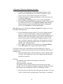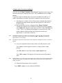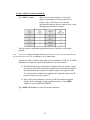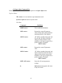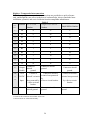
1
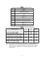
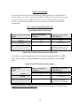
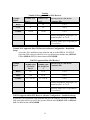
Trans-Cal Industries, Inc.
Model SSD120-(XX)A & Model SSD120-(XX)AE
All Solid State
High Altitude Series 85,000 to 100,000 Feet
Altitude Encoder/Digitizer
Owner/Installation Manual
T.S.O. C88a Approved
Trans-Cal Industries, Inc.
Van Nuys Airport
16141 Cohasset Street
Van Nuys, CA 91406-2908
(818)787-1221 * (800)423-2913 * (818)787-8916FAX
www.trans-cal.com
3 September 2004
Document Number: 881400-100
1
Revision: E
This document may not be reproduced, transmitted, or copied in any form without the
prior written consent of Trans-Cal Industries, Inc. The data contained herein is subject
to change without notice.
Please Note:
It is the responsibility of the installer of this equipment, within a specific type or
class of aircraft,
to determine that the aircraft operating conditions are within TSO standards.
Trans-Cal Industries, Inc. 16141 Cohasset
Street Van Nuys, CA 91406
818/787-1221 800/423-2913 FAX 818/7878916 www.trans-cal.com
History of Revision
Revision
Date
Description
07/98
Production release.
A
03/00
Added TDR950 & SL70 data Table IV. Changed Oper. Voltage +14 to +9 page 1.
B
04/00
Added GTX327 Data Table II & GPS Connection Data.
C
11/00
Added TxD2 data and rev. A outline drawing.
D
12/00
Revised serial port data.
E
9/04
Updated Manual.
2
Table of Contents
Section 1.0 Introduction...................................................................................................... 4
1.1 Scope......................................................................................................................... 4
1.2 Equipment Description ............................................................................................. 4
1.3 General Specifications .............................................................................................. 4
1.3.1 Operating Altitude ............................................................................................. 5
1.3.2 Accuracy ............................................................................................................ 5
1.3.3 Serial Port Altitude Data Resolution.................................................................. 5
1.3.4 Mechanical Characteristics ................................................................................ 5
1.3.5 Environmental.................................................................................................... 6
1.3.6 Over Range ........................................................................................................ 6
1.4 Parallel Altitude Data Port Specifications ................................................................ 6
1.5 Serial Port Specifications.......................................................................................... 7
1.6 Serial Communication Format.................................................................................. 7
1.7 Serial Communication Protocol................................................................................ 8
Section 2.0 Operation.......................................................................................................... 9
2.1 General...................................................................................................................... 9
2.2 Operating Instructions............................................................................................... 9
Section 3.0 Installation and Calibration............................................................................ 10
3.1 Mechanical Installation........................................................................................... 10
3.2 Electrical Installation .............................................................................................. 10
3.3 Serial Altitude Data Port Test Equipment .............................................................. 11
Section 4.0 Calibration and Configuration ....................................................................... 12
4.1 Calibration Overview.............................................................................................. 12
4.2 Required Equipment Dynamic Calibration:............................................................ 12
4.3 Hyper Terminal Set-Up on the IBM Compatible PC.............................................. 13
4.4 Serial Port Software Configuration......................................................................... 14
4.5 Dynamic Calibration Adjustment Procedure .......................................................... 15
4.6 Configuration and Dynamic Calibration Command List........................................ 17
4.7 Error Correction Table............................................................................................ 18
4.8 Required Equipment Span Adjust: (See span adjust block drawing.) .................... 19
4.9 Span Adjust Procedure............................................................................................ 19
4.10 Span Adjust Command List .................................................................................. 23
Digitizer / Transponder Interconnections ......................................................................... 24
Temperature vs. Warm-up Time....................................................................................... 33
Span Adjust Block Diagram ............................................................................................. 34
Dynamic Calibration Block Diagram ............................................................................... 35
Wiring Harness Diagram .................................................................................................. 36
Outline Drawing................................................................................................................ 37
3
Section 1.0 Introduction
1.1 Scope
This manual provides detailed installation, calibration and operating
instructions for Trans-Cal Industries’ Model SSD120-(XX)A and SSD1201
(XX)AE series of high altitude (85,000 feet and above) encoder/digitizer.
1.2 Equipment Description
Approved under F.A.A. TSO-C88a, the Model SSD120-(XX)A and
SSD120-(XX)AE is an all solid state electronic device which when connected to
an aircraft static and electrical system, converts pressure altitude information into
parallel and serial digital data.
The parallel digital altitude data protocol is set forth in the (ICAO)
International Standard for SSR Pressure Altitude Transmission. In accordance
with U.S. National Standards for Common System Component Characteristics for
the I.F.F. Mark X (SIF)/Air Traffic Control Radar Beacon System SIF/ATCRBS.
The serial altitude data is provided on (2) two asynchronous RS232
output ports. The serial data protocol is individually selectable for each port
(refer to Table V & VI and Section 4.4) and may be used to provide pressure
altitude data to GPS or other on board navigation devices.
1.3 General Specifications
Operating Voltage: Model SSD120-(XX)A
Model SSD120-(XX)AE 2
+9 to 30 VDC.
+26 to 30 VDC.
Operating Current: Model SSD120-(XX)A
0.1 Amps.
Model SSD120-(XX)AE
Model SSD120-(XX)AE
0.1 Amps. 0° to +70°C.
1.0 Amps. 0° to -55°C.
Operating Temperature: Model SSD120-(XX)A -20° to +70°C. Model SSD120(XX)AE -55° to +70°C.
Storage Temperature (non-operating) all models: -65°C to +85°C.
Weight: 17 oz.
1
SSD120-(XX)AE Extended operating temperature range: -55°C to +70°C.
2
The low temperature heat circuit is designed to be operated at +28VDC, but the SSD120-(XX)AE model
may be operated at +12VDC if the operating temperature does not fall below 0°C.
4
1.3.1 Operating Altitude
Model SSD120-85A( ) -1000 to +85,000 feet. Model SSD120-100A( ) -1000 to
+100,000 feet.
1.3.2 Accuracy
Model SSD120-(XX)A:
Accuracy throughout operating temperature range -20° to
+70°C
-1000 to +42,000 feet ±50 feet.
+42,100 to +62,000 ±75 feet.
+62,100 to maximum altitude ±125 feet.
Model SSD120-(XX)AE
Accuracy from -30° to +70°C:
-1000 to +42,000 feet ±50 feet.
+42,100 to +62,000 feet ±75 feet.
+62,100 to maximum altitude ±125 feet.
Accuracy from -55° to -31°C:
-1000 to +42,000 feet ±75 feet.
+42,000 to +62,000 feet ±125 feet.
+62,100 to maximum altitude ±175 feet.
Accuracy after 15 minute warm-up at -55°C: (See figure 1
for warm-up/start-up time.) -1000 to +42,000 feet ±50 feet.
+42,100 to +62,000 feet ±75 feet. +62,100 to maximum
altitude ±125 feet.
1.3.3 Serial Port Altitude Data Resolution
The default resolution of the altitude digitizer serial data is
100 feet. To enable 10 foot resolution, connect pin 2 of the
9 pin D-Subminiature connector to ground (see Table V.)
The serial port resolution may also be configured via
software, see Section 4.4.
1.3.4 Mechanical Characteristics
Model Number
Model SSD120-85A( )
Model SSD120-100A( )
Dimensions
See Outline Drawing
See Outline Drawing
5
Weight
17 oz.
17 oz.
1.3.5 Environmental
All model SSD120-(XX)A( ) digitizers have been designed,
tested and approved under the requirements of TSO-C88a,
in accordance with RTCA Document DO160b, dated July
1984 (specifics provided upon request.)
1.3.6 Over Range
The SSD120-(XX)A( ) series of altitude digitizers will not
be damaged when operated beyond their specified
maximum altitude up to pure vacuum feet MSL, or over
pressured to 18 psi max.
1.4 Parallel Altitude Data Port Specifications
Code Format:
In accordance with U.S. National Standard for Common
System Component Characteristics for the IFF Mark X
(SIF) Air Traffic Control Radar Beacon System,
SIF/ATCRBS.
Driver Description:
The parallel altitude data output is provided by the
“uncommitted” collectors of a transistor array and must be
“pulled-up” through a resistive load by the transponder.
Pull-Up Voltage:
+3 to 50VDC.
Maximum Sink Current:
25 milliamperes.
Maximum Cable Length:
4000 feet.(1219 meters)
Input Signal Requirement:
Pin 6 (strobe or signal common) must be either grounded or
connected to the transponder.
6
1.5 Serial Port Specifications
Electrical Format:
Conforming to the TIA/EIA RS-232E standard.
Logic Levels:
“0”, +9 volts. Logic “1”, -9 volts.
Driver Output Maximum Voltage:
±25 VDC.
Driver Load Impedance:
3KOhm typ.
The TIA/EIA RS232E standard recommends one receiver per serial port.
Maximum Cable Length:
50 Feet.(15.24 meters)
Code Format:
ASCII
Communication System:
Simplex (Talk Only).
Transmission Method:
Asynchronous.
Transmission Rate:
Selectable, 1200 bps to 9600 bps.
Update Rate:
10/sec.
1.6 Serial Communication Format
Model SSD120-(XX)A( ) carries out serial communication
asynchronously with the “Start/Stop” system. The specifics of the format,
i.e. the number of data bits, baud rate etc., is determined by the protocol
selected.
7
1.7 Serial Communication Protocol
(Refer to Table V & VI and Section 4.4)
Protocol is user selectable by grounding or leaving open pin 6 or pin 7 of
the 9 pin D-Subminiature connector, or by selecting protocols via software see
Section 4.4. Note: The following hardware jumpers will override any
software settings described in Section 4.4.
Leaving pin 6 and 7 of the 9 pin connector open results in a protocol
compatible with UPS Aviation Technologies’ (IIMorrow) Navigation devices. At
a baud rate of 1200 bps the Digitizer sends a seventeen byte message beginning
with # AL, then a space followed by five altitude bytes; the letter “T” and the
number “25”; two checksum bytes and a carriage return. Examples of serial
messages for (IIMorrow) devices:
Message: Definition:
#AL +00800T+25D8r Altitude 800 feet
Grounding pin 7 of the 9 pin connector results in a protocol compatible
with some navigation devices manufactured by Trimble and Garmin. At a baud
rate of 9600 bps the Digitizer sends a ten byte message. The message begins with
ALT followed by a space and five altitude bytes; concluding with a carriage
return. Examples of serial messages for Trimble or Garmin devices:
Message:
ALT 99900 r
ALT 10500 r
Definition:
Digitizer disabled.
Altitude 10,500 feet.
Grounding pin 6 of the 9 pin connector results in a protocol compatible
with some navigation devices manufactured by Northstar and Garmin. At a baud
rate of 2400 bps the Digitizer sends a 10 byte message. The message begins with
ALT followed by a space and five altitude bytes; concluding with a carriage
return. Examples of serial messages for these devices:
Message Definition:
ALT 02500 r Altitude 2500 feet.
ALT -2500 r Digitizer disabled.
Grounding both pins 6 and 7 of the 9 pin connector results in a protocol
compatible with some navigation devices manufactured by Magellan. At a baud
rate of 1200 bps the Digitizer sends a seventeen byte message beginning with
$MGL, followed by a +/sign and five altitude digits, then T+25, a checksum and
concludes with a carriage return. Examples of serial messages for Magellan
devices:
Message Definition:
$MGL+02500T+25D6 r Altitude 2500 feet.
8
Section 2.0 Operation
2.1 General
The SSD-120(XX)A( ) series of altitude digitizer’s are designed to
be mounted within a pressurized or non-pressurized, but temperature
controlled area within aircraft operating up to 100,000 feet MSL. Usually
remotely located, the digitizer is fully automatic in operation. The parallel
data output is controlled by the transponder while the serial altitude data is
transmitted asynchronously.
2.2 Operating Instructions
Parallel Data: Place the transponder in mode “C” altitude reporting
mode, and apply power to the transponder and to the digitizer. In some
installations the digitizer will automatically be supplied power when the
transponder is energized; in others, power to the digitizer may be through
a separate circuit breaker. If power to the digitizer is provided directly
from the aircraft’s avionics buss, follow the power-up procedures
recommended by the transponder manufacturer. Upon power-up the
parallel data will assume the value for the present input pressure. In some
installations, the transponder controls the digitizer by enabling and
disabling its outputs. In other installations, the digitizer’s output is not
controlled by the transponder and is continuously enabled, (Digitizer pin 6
is grounded.)
Serial Data The serial communication is fully automatic and
transmission begins after the self-test/warm-up is complete. Strobing the
parallel data output of the digitizer will not affect the serial data
transmission.
9
Section 3.0 Installation and Calibration
3.1 Mechanical Installation
The SSD120(XX)A( ) series of digitizer may be mounted in any
attitude within the internal structure of the aircraft. DO NOT mount the
digitizer in the direct airstream of either hot or cold air ducts. The
mounting position should allow for a short pressure line from the digitizer
to the altimeter, access to the digitizer’s adjustments, and ample room for
a service loop for the interconnecting cabling to the transponder.
Use #4-40 machine screws, sheet metal screws, or pop rivets to
attach the digitizer or the mounting tray to the airframe. Secure mating
connectors to the digitizer housing using the #4-40 screws provided. Refer
to the outline drawing for mechanical dimensions and the installation
block diagram.
3.2 Electrical Installation
The digitizer is designed to operate with either a 14 or 28 VDC
power source. These voltages can be A+ switched power provided by the
transponder or can be provided by the avionics buss. If using the avionics
buss, protect the circuit with a fuse or circuit breaker.
Parallel Data Connection The outline drawing provides electrical
connector pin/function information. Use this data when connecting the
digitizer to the transponder. In some installations where older transponders
are used, the transponder may not provide an “altitude disable” function.
In this case, an instrument panel mounted switch for this function may be
required.
Serial Data Connection (Table V lists the pin assignments for the serial port
3
connector.) Connect the TxD1 or TxD2 (transmit data) from the 9 pin DSubminiature connector to the RxD (receive data) port on the GPS or other
navigation device. All grounds on the 9 pin D-subminiature connector are
internally connected to ground and may be used to ground protocol pins,
as well as provide data ground to the receiving GPS or other device. Pin 3
(RxD) of the 9 pin connector is used for calibration only. See Table V for
connector pin assignments, Section 4.4 for software assigned protocols,
and Section.
4.5 for calibration data. Shielded cable is recommended for both
serial and parallel data wiring harnesses.
10
3.3 Serial Altitude Data Port Test Equipment
The output of the serial port may, or may not be directly displayed
by the GPS or other device receiving the serial data. There are several
ways to test the output of the serial port:
1.
Connect to an open serial port on a personal computer
using serial data capture software such as
PROCOMM™, VERSATERM™, SOFTWARE
WEDGE™, TERMINAL (Windows® 3.x) or
HYPERTERMINAL (Windows® 95 & 98).
2.
Use a dedicated serial data test box such as the BLACK
BOX™ RS232 Monitor.
c) Test for a serial output using an oscilloscope to view
the 9 VDC square wave
transmitted about ten times a second.
3.4 Parallel Altitude Data Port Test Equipment
The output of the parallel altitude data may be monitored by any number
of transponder ramp test sets which allow display of the altitude digitizer/encoder
code. Alternatively, the Trans-Cal Industries’ ATS-200 may be used to display
the parallel data.
The selected serial data protocol is transmitted simultaneously on both TxD1 and TxD2, unless assigned
separately via Serial Port Software Configuration see Section 4.4 .
11
Section 4.0 Calibration and Configuration
4.1 Calibration Overview
This procedure will allow adjustment to the calibration curve of the
SSD120-(XX)A or SSD120-(XX)AE as an aide in matching the digitizer
output to a primary flight altimeter or NIST traceable pressure standard.
The maximum allowed error between the primary flight altimeter and the
altitude digitizer is ±125 feet as required by TSO-C88a. All Trans-Cal
digitizers are calibrated to NIST traceable pressure standards; however,
the error allowed on altimeters at higher altitudes can lead to a combined
error in excess of ±125 feet. This device may be adjusted utilizing an
externally addressable EEPROM which is configured to accept an
alternate altitude error curve entered to the digitizer via an IBM
compatible PC.
As an alternative to Dynamic Calibration the span of the transducer
itself may be adjusted via the span adjust procedure. The technician may
perform which ever procedure seems best suited for the application at
hand. It is not required to perform both procedures.
4.2 Required Equipment Dynamic Calibration:
(See dynamic calibration block diagram.)
1. Primary flight altimeter or NIST traceable pressure standard.
2. +12 to 28VDC power supply.
3. IBM compatible computer with an available serial port.
4. Software requirement: Windows 98® using Hyper Terminal Ver. 5.0 by
Hilgraeve. (Available as a free download at http://www.hilgraeve.com)
(Software Note: The Hyper Terminal program which is shipped with
Windows 98® will not function correctly. You must download Version
5.0 or better, to calibrate this device.)
5. A pitot-static test set, capable of exercising the altimeter and digitizer over
a range of -1000 feet to the maximum altitude of the digitizer.
6. Optional: ATS-200 or equal device which will allow the display of the
100 foot resolution parallel altitude data.
12
4.3 Hyper Terminal Set-Up on the IBM Compatible PC
Boot up the computer and start the Hyper Terminal program.
Hyper Terminal may be located in the Programs section or in the
Accessories section under Communications .
Under the New Connection window. (Identifies the new
connection.) -Choose an icon then select an identifying title such as
“Test.” Select OK after you have made your choices.
Under the Connect to window (Selects the Com port to use.) Choose Connect Using Com 1 or whatever Com port you have chosen to
use. After your selection click on OK.
Under the Com ? Properties, (Sets communication properties.)
Under the Port Settings tab, set the following:
Bits per second:
Data bits:
Parity:
Stop Bits:
Flow Control:
9600
8
None
1
None
Select OK
In the Hyper Terminal window select File then click on Properties.
Under the Com ? Properties window click on the Settings tab. Set the following:
Function, arrow, ctrl keys to act as Terminal Keys. Emulation to Auto Detect
Under ASCII Setup Set the following:
Echo off.
Wrap lines that exceed terminal width.
Select OK.
The software is now configured for operation.
13
4.4 Serial Port Software Configuration
This device incorporates two separate RS232E compatible outputs
which may be configured via software to transmit 2 different altitude data
protocols simultaneously.
Connect the digitizer to an IBM compatible computer running
Hyperterminal as described in Section 4.3 and as shown in the Dynamic
Calibration Block Diagram. Assign the serial port protocols as follows:
Apply power to the digitizer and after the self test time has elapsed
data will appear on the PC screen.
Type <enter> The digitizer will respond with ?>(current altitude)
Type ADJ <enter>
Accesses the digitizer adjustment program. The Digitizer responds A=
Type P
<enter>
To identify the current serial port settings.
The digitizer will respond with a three digit number as follows:
Serial Altitude Data Resolution
TxD2 Protocol
TxD1 Protocol
1. The first digit represents the serial altitude data resolution.
0= Use D-Sub connector protocol hardware jumpers.
1= 100 foot resolution on TxD1 and TxD2.
2= 10 foot resolution on TxD1 and TxD2.
2. The second digit represents the protocol selection for TxD1.0= Use D-Sub
connector protocol hardware jumpers.
1= UPS Aviation Technologies. 1200bps.
2= Trimble/Garmin. 9600bps.
3= Northstar. 2400bps.
4= Magellan, 1200bps.
5= ARNAV, 9600bps.
3. The third digit represents the protocol selection for TxD2.
0= Use D-Sub connector protocol hardware jumpers.
1= UPS Aviation Technologies. 1200bps.
2= Trimble/Garmin. 9600bps.
3= Northstar. 2400bps.
4= Magellan, 1200bps.
5= ARNAV, 9600bps.
Example:
Type P212<enter>
Defined as 10 foot resolution on TxD1 and TxD2. UPS Aviation Technologies
protocol transmitted on TxD1. Trimble/Garmin protocol transmitted on TxD2.
14
4.5 Dynamic Calibration Adjustment Procedure
1. Construct a wiring harness per the wiring harness diagram. (This
harness may be ordereddirectly from Trans-Cal Industries. Please
specify 9 pin or 25 pin connector. Request P/N: 881404.)
2. Connect the digitizer, computer and altimeter as shown in the test setup diagram, andenergize.
3. Open the Hyper Terminal program as described in Section 4.5.
4. The digitizer output should now be displayed on the PC screen with 10
foot resolution.(You may use the Hyper Terminal “Clear Screen”
function to remove any extra characters that may be cluttering the
screen. Click on Edit then click on Clear Screen.)
Note: Backspace does not function in Hyper Terminal. If a typing error occurs,
hit <enter> and begin again.
5. Set the altimeter barometric input to 29.92 In. Hg. Change the input
pressure to -1000 feet and begin to compare the altitude digitizer
output, as displayed on the computer, to the altimeter reading at every
1000 foot mark. When the digitizer output begins to differ from the
altimeter by more than ±30 feet begin to change the digitizer error
curve. (Section 4.9 provides a table to give the technician a record of
changes required and implemented.) (Note: no digitizer correction is
possible at the -1000 foot mark.)
6. Type <enter> the Digitizer will respond with ?>(current altitude)
7. Type ADJ <enter> The computer will respond with A=
CAUTION: Always refer to the altimeter and VSI manufacturer’s data for
maximum rate of climb or descent and any special test conditions which must be
complied with.
8. Adjust the input pressure until the altimeter is exactly reading a 1000
foot mark. Note thedifference between the digitizer and the altimeter
and adjust as required.
Example:
The altimeter reads 10,000 and the digitizer reads 10,080.
Type “S10 <enter>”
(S10 represents Set 10,000feet)
The digitizer will now output 10,000 feet based on the current input
pressure. The PC will display the altitude at which the digitizer will make
this change. In the example above the PC would display >10000.
9. Proceed to the next 1000 foot mark and repeat the procedure, as in step
8 above, until the entire operating range of the digitizer is completed.
15
4.5 Dynamic Calibration Adjustment Procedure(continued)
(Note: If no correction is required at an altitude simply do not enter a correction.
The technician does not have to enter 000.)
You may quit the adjustment program at any time by typing “Q” twice, the
digitizer output will then be displayed on the PC screen.
10. After completing the above procedure you may examine the
corrections entered into theEEPROM. Type “D<enter>” to dump the
EEPROM data and read the current error curve on the PC screen. The
following table should appear:
00= 000
06= 000
12= 000
18= 000
24= 000
30= 000
36= 000
42= 000
48= 000
54= 000
60= 000
66= 000
71= 000
77= 000
83= 000
89= 000
95= 000
>current altitude
01= 000
07= 000
13= 000
19= 000
25= 000
31= 000
37= 000
43= 000
49= 000
55= 000
61= 000
66= 000
72= 000
78= 000
84= 000
90= 000
96= 000
02= 000
08= 000
14= 000
20= 000
26= 000
32= 000
38= 000
44= 000
50= 000
56= 000
62= 000
67= 000
73= 000
79= 000
85= 000
91= 000
97= 000
03= 000
09= 000
15= 000
21= 000
27= 000
33= 000
39= 000
45= 000
51= 000
57= 000
63= 000
68= 000
74= 000
80= 000
86= 000
92= 000
98= 000
04= 000
10=-080
16= 000
22= 000
28= 000
34= 000
40= 000
46= 000
52= 000
58= 000
64= 000
69= 000
75= 000
81= 000
87= 000
93= 000
99= 000
05= 000
11=000
17= 000
23= 000
29= 000
35= 000
41= 000
47= 000
53= 000
59= 000
65= 000
70= 000
76= 000
82= 000
88= 000
94= 000
The first two digits represent altitude x1000 feet and the last three digits after the equal
sign represent the amount of error introduced at the altitude in feet.
16
4.6 Configuration and Dynamic Calibration Command List
Following is a list of commands which will operate in the ADJ mode using
Hyper Terminal.
Top Level Menu:
ADJ <enter> Enter Adjustment mode.
Q <enter>
Quit and return to operate mode.
Sub-Menu
CLR <enter> Clear all EEPROM data.
D <enter>
Dump to list all EEPROM data.
P <enter>
Displays current serial Port settings, see Section
4.6 Serial Port Software Configuration.
Pabc<enter> Port protocol select, see Section 4.6 Serial Port
Software Configuration.
Q<enter>
Quit and return to top level menu.
Saa<enter>
Set digitizer to 1K altitude (aa) mark at current
input pressure.
NOTES:
1. Backspace does not function. If a typing error occurs hit <enter> and begin again.
2. 1K altitude values 90 to 99 in EEPROM contain factory calibration data and are
not customer accessible.
3. A maximum error of ±499 feet may be introduced at any one altitude.
4. CLR clears all error data in the EEPROM.
5. ERR indicates syntax error.
17
4.7 Error Correction Table
Altitude
Correction
Altitude
Correction
Altitude
Correction
Altitude
-1000
25000
51000
77000
0
26000
52000
78000
1000
27000
53000
79000
2000
28000
54000
80000
3000
29000
55000
81000
4000
30000
56000
82000
5000
31000
57000
83000
6000
32000
58000
84000
7000
33000
59000
85000
8000
34000
60000
86000
9000
35000
61000
87000
10000
36000
62000
88000
11000
37000
63000
89000
12000
38000
64000
90000
13000
39000
65000
91000
14000
40000
66000
92000
15000
41000
67000
93000
16000
42000
68000
94000
17000
43000
69000
95000
18000
44000
70000
96000
19000
45000
71000
97000
20000
46000
72000
98000
21000
47000
73000
99000
22000
48000
74000
23000
49000
75000
24000
50000
76000
18
Correction
4.8 Required Equipment Span Adjust: (See span adjust block drawing.)
1. NIST traceable pressure standard. Accuracy better than 0.05% FS is
required, 0 to 15 psi.
2. +28VDC power supply.
3. IBM compatible computer with an available serial port.
Software requirement: Windows 98® using Hyper Terminal Ver. 5.0 by
Hilgraeve. (Available as a free download at
http://www.hilgraeve.com)(Software Note: The Hyper Terminal program
which is shipped with Windows 98® will not function correctly. You
must download version 5.0 or better to use this calibration program.)
4. Digitizer/PC interface cable. (See wiring harness diagram or special order
from Trans-Cal.)
5. Vacuum and pressure source and control capable of exercising the
digitizer/pressure standard over the digitizer’s operating range. (Note: The
static system needs to be very stable or nearly leak free.)
(Optional: ATS-200 or equal device which will allow the display of the
parallel 100 foot altitude data.)
4.9 Span Adjust Procedure
1. Construct a wiring harness per the wiring harness diagram.
2. Connect the digitizer and computer as shown in the span adjust test set-up
diagram, andenergize.
3. Open and configure the Hyper Terminal program as described in Section
4.3.
4. The digitizer output should now be displayed on the PC screen with 10
foot resolution.(You may use the Hyper Terminal “Clear Screen”
function to remove any extra characters that may be cluttering the screen.
Click on Edit then click on Clear Screen.)
5. Adjust input pressure until the pressure standard reads the maximum
operating altitude of the
Note: Backspace does not function in Hyper Terminal. If a typing error occurs, hit
<return> and begin again.
digitizer.
SSD120-50A(E) 50,000 feet 3.4247 In.Hg.
SSD120-62A(E) 62,000 feet 1.9237 In.Hg
SSD120-65A(E) 65,000 feet 1.6654 In.Hg.
SSD120-80A(E) 80,000 feet 0.8155 In. Hg.
19
4.9 Span Adjust Procedure(continued)
6. Note the digitizer pressure as displayed on the Hyper Terminal. Calculate
the digitizer error:
Example:
The pressure standard reads 62,000 and the digitizer serial output on
the PC reads: ALT 61,910
Error = (61910 - 62000= -90) Adjust the Z parameter to correct this error.
Each number added or subtracted from the Z parameter results in an
approximate 10' correction at 62,000 feet.
Note:
If the digitizer reads low in relation to the manometer, as in the case above, then a negative
correction is required. In the above case a command of *00Z= -9<return> would yield
approximately a 90 foot change.
Note:
If the digitizer transition is high in relation to the manometer reading then a positive correction is
applied.
7. Access the adjustment feature and read the current Z parameter value:
Type <enter>, until the digitizer returns a ? along with the current
pressure.
Type XD <enter> to enter the Span Adjust mode.
Type *00Z= <enter> The digitizer will return the current Z parameter
value.
Note:
The Z parameter is set at the factory when compared to a NIST traceable pressure standard. Write
down the current factory value before proceeding so that you may return to the original factory
setting, if required.
8. Change the Z parameter value as required:Type *00WE <enter> to write
enable the EEPROM.
Type *00Z=N<enter> Where N represents a number to correct the
digitizer Z parameter. (No sign required for a positive value.) The factory
error must be taken into account when changing any parameter. Example:
20
4.9 Span Adjust Procedure(continued)
(You may use the Hyper Terminal “Clear Screen” function to remove any extra
characters that may be cluttering the screen. Click on Edit then click on Clear
Screen.)
Compare the digitizer altitude data to the pressure standard at 62,000 feet. If
further adjustments are required, repeat the Z parameter correction as above.
9. If the digitizer is within ±20 feet of the pressure standard at the digitizer
maximum operating altitude, adjust the input pressure to 1000 feet or
28.8557 In. Hg.
10. Note the digitizer pressure as displayed on the Hyper Terminal.
Calculate the digitizer error at 1000 feet: Example: the pressure standard
reads 1,000 and the digitizer serial output on the PC reads: ALT 990 Error
= (990 - 1000= -10) Adjust the X parameter to correct this error. Each
number added or subtracted from the X parameter results in an
approximate 1' correction at 1,000 feet.
Note:
If the digitizer reads low in relation to the manometer, as in the case above, then a negative
correction is required. In the above case a command of *00X= -10<return> would yield
approximately a 10 foot change.
Note:
If the digitizer transition is high in relation to the manometer reading then a positive correction is
applied.
11. Access the adjustment feature and read the current X parameter value:
Type <enter>, until the digitizer returns a ? along with the current
pressure.
Type XD <enter> to enter the transducer Span Adjust mode.
Type *00X= <enter> The digitizer will return the current X parameter
value.
Note:
The X parameter is set at the factory when compared to a NIST traceable pressure standard. Write
down the current factory value before proceeding so that you may return to the original factory
setting, if required.
12. Change the X parameter value as required:
2
Type *00WE <enter> to write enable the E PROM.
21
4.9 Span Adjust Procedure(continued)
Type *00X=N<enter>
Where N represents a number to correct the
digitizer X parameter. (No sign required for a
positive value.) The factory error must be
algebraically added to the new required error, when
changing any parameter. Example:
Type Q to quit the adjustment program and return to read the current input
pressure.
Note: You may use the Hyper Terminal “Clear Screen” function to remove any extra characters that
may be cluttering the screen. Click on Edit then click on Clear Screen.
Compare the digitizer altitude data to the pressure standard at 1,000 feet. If further
adjustments are required, repeat the X parameter correction as above.
13. The X and Z parameter adjustments do slightly affect one another. Adjust
the input pressure until the pressure standard reads the maximum digitizer
operating altitude and compare the digitizer output, as displayed on the
PC, to the pressure standard. If an adjustment is required, return to the Z
parameter and repeat steps 5 thru 12.
14. After verifing the calibration is correct at 1000 feet and the maximum
altitude, store yourchanges in the transducer memory. Type *00WE
<enter> to write enable the EEPROM.
Type *00SP=ALL<enter> to store all current parameters.
22
4.10 Span Adjust Command List
Following is a list of commands which will operate in the Span Adjust mode.
Top Level Menu
XD <return> Access transducer span adjustment mode.
Q<enter> Quit and return to operate mode.
Sub-Menu
Command
Definition
*00WE<enter>
Write enable the EEPROM.
*00Z=<enter>
Returns the current Z parameter
value Set this value at the maximum
operating altitude of the digitizer.
*00Z=N<enter>
“N” defines a number between 0 and
50 or 0 and -50 which will affect a
change in the Z parameter of the
transducer. (No sign is required for a
positive number.) Example:
*00Z=5<enter>
*00X=<enter>
Returns the current X parameter
value
*00X=N<enter>
“N” defines a number between 0 and
100 or 0 and 100 which will affect a
change in the reference span of the
transducer. (No sign is required for a
positive number.) Example:
*00X=5<enter>
*00SP=ALL<enter>
Stores the all current parameter
settings.
Q
Quit adjustment program and return
to top level menu.
23
Digitizer / Transponder Interconnections
The following digitizer/transponder interconnections are provided as a quick reference
only, and though they are correct to the best of our knowledge, always consult the latest
installation, operation, and service bulletins from the transponder manufacturer.
Table I
Function KT76/78 Pin
SSD120
King KT76A/78A Pin
15 Pin
King KXP Pin Number
Conn.
Number
Number
1
D4
*4
*4
V
2
A1
6
M
G
3
A2
7
K
H
4
A4
9
J
J
5
B1
4
E
K
9
B2
1
C
L
10
B4
2
B
M
11
C1
3
D
P
13
C2
8
L
R
12
C4
10
H
S
6
Output
Enable
8 or
14 to
14
28VDC
*5
Input.
15
Ground
Connect to
aircraft
ground.
Connect to aircraft
ground.
Connect to aircraft
ground.
Connect to
Connect to aircraft’s
avionics buss protected
aircraft’s avionics
by
buss protected by a fuse or circuit breaker.
a fuse or circuit
breaker.
Connect to
Connect to aircraft
aircraft ground.
ground.
*4 Data for this connection not available at this time.
*5 Pins 8 and 14 are connected internally.
24
Connect to aircraft’s
avionics buss protected
by a fuse or circuit
breaker.
Connect to aircraft
ground.
Table II
SSD120
15 Pin
Conn.
Function
Cessna RT359A,
RT459A, RT859A
Narco AT-150 AT-50,
AT-50A Pin
Number
Narco AT-6A AT-5,
AT-6 Pin Number
Garmin GTX 327
Pin Number
Pin Number
1
D4
10
*6
*6
18
2
A1
14
7
2
3
3
A2
13
6
4
5
4
A4
15
8
8
6
5
B1
19
12
9
9
9
B2
17
10
10
11
10
B4
16
9
11
12
11
C1
21
14
1
10
13
C2
18
11
3
4
12
C4
20
13
5
7
6
Output
Enable
11
5
12
13 or 25 or
aircraft ground
14 to
28VDC
Input
9
18
13
14 to 28VDC
Input
14
Connect to
aircraft ground.
8 or
14 *7
15
Ground
Connect to
aircraft
ground.
Connect to
aircraft
ground.
*6 Data for this connection not available at this time.
*7 Pins 8 and 14 are connected internally.
25
Serial Data Connection for the Garmin GTX327 Transponder
SSD120-(XX)A 9 Pin Conn.
Function
GTX 327 25 Pin
Conn.
4 or 9
TxD to RxD
19
1 or 5 or 8
Ground
13 or 25
Protocol, Connect pin 7 to ground.
To allow the Garmin GTX 327 transponder to communicate with the SSD120-(XX)A go
to the Setup Page and set the Altitude Source (ALT SRC) to receive data in the Icarus
RS232 format.
26
Table III
SSD120
Function
Edo-Air
Genave
Collins
Radair
RT-777
Pin Number
Beta 5000
Pin Number
TDR 950
Pin Number
250
Pin Number
15 Pin
Conn.
1
D4
15
0
3
15
2
A1
7
4
12
7
3
A2
5
5
10
6
4
A4
3
6
7
13
5
B1
12
7
6
9
9
B2
13
8
5
10
10
B4
14
9
4
11
11
C1
8
10
8
14
13
C2
6
11
11
16
12
C4
4
12
9
12
2
3
Connect to
aircraft’s
avionics
buss protected
by a fuse or
circuit breaker.
2
2
Connect to
6
Output
Enable
8 or
14 to
14
28VDC
*8
Input
15
Ground
Connect to
aircraft
ground.
Connect to
19
22
aircraft’s
avionics buss
protected by a
fuse or circuit
breaker.
aircraft ground.
*8 Pins 8 and 14 are connected together internally.
27
Connect to
aircraft
ground.
Connect to
aircraft
ground.
Function
Bendix
TPR-2060
Pin Number
Table IV
Bendix
TR641A/B
Pin Number
1
D4
*9
N
C
35
2
A1
4
A
k
13
3
A2
6
B
c
31
4
A4
8
C
W
12
5
B1
9
D
T
33
9
B2
10
E
L
14
10
B4
11
F
D
32
11
C1
3
H
P
16
13
C2
5
J
f
34
12
C4
7
K
Z
15
6
Output
Enable
SSD120
15 pin
Conn.
Connect to aircraft
ground.
Connect to aircraft
ground.
Connect to
Wilcox
1014A
Pin Number
UPS AT
Apollo SL70
Pin Number
Connect to aircraft
ground.
Connect to
Connect to aircraft
ground.
Connect to
Connect to
aircraft’s avionics
aircraft’s avionics
aircraft’s avionics
aircraft’s avionics
*10
14 to
28VDC
Input
buss protected by a
fuse or circuit
breaker.
buss protected by a
fuse or circuit
breaker.
buss protected by a
fuse or circuit
breaker.
buss protected by a
fuse or circuit
breaker.
15
Ground
Connect to aircraft
Connect to
Connect to aircraft
Connect to aircraft
8 or
14
ground.
aircraft ground.
ground.
ground.
Serial Altitude Data Connection for the Apollo SL70 Transponder
SSD120-(XX)A
9 Pin Conn.
Function
UPS AT
SL70
4 or 9
TxD to RxD
4
1 or 5 or 8
Ground
3
To allow the UPS AT SL70 transponder to accept serial data from the SSD120-(XX)A go to the Test
Mode on the SL79 Conf page and set the Altitude Source (ASrc) to receive Serial (Ser) data. On the
BAUD page select 1200.
*9 Data for this connection not available at this time.
*10 Pins 8 and 14 are connected internally.
28
Table V
Serial Port Connector, 9 Pin D-Subminiature DE-9S
Pin
Function
1
Ground *11
2
Ground for 10' resolution.
3
RxD
4
TxD1 *12
5
Ground *11
6
Protocol select, see function Table VI below.
7
Protocol select, see function Table VI below.
8
Ground *11
9
TxD2 *12
Table VI
Protocol Selection: DE-9S D-Subminiature Connector Function Table
Protocol Selection
Pin
Pin
Pin
2
6
7
UPS AT 100' resolution, 1200bps.
UPS AT 10' resolution, 1200bps.
Open
Gnd.
Open
Open
Open
Open
Trimble/Garmin, 100' resolution, 9600bps.
Trimble/Garmin, 10' resolution, 9600bps.
Open
Gnd.
Open
Open
Gnd.
Gnd.
Northstar/Garmin, 100' resolution, 2400bps.
Northstar/Garmin, 10' resolution, 2400bps.
Open
Gnd.
Gnd.
Gnd.
Open
Open
Magellan, 100' resolution, 1200bps.
Magellan, 10' resolution, 1200bps.
Open
Gnd.
Gnd.
Gnd.
Gnd.
Gnd.
*11
*12
Pins 1 and 5 and 8 are internal grounds provided for protocol selection and serial data ground.
TxD1 and TxD2 are two (2) separate RS232 outputs which will transmit the protocol selected by
grounding the pins above, or will transmit separate protocols as assigned via software, see Section
4.4 Serial Port Software Configuration. Note: The hardware jumpers override any software
serial port settings.
29
GPS Connection Data
Given the speed with which new GPS units are entering the market, it is impossible to
provide data on every device. The following digitizer/GPS interconnections are provided
as a quick reference only, and though they are correct to the best of our knowledge,
always consult the latest installation, operation, and service bulletins from the GPS
manufacturer.
UPS Aviation Technologies (IIMorrow)
Apollo Model GX50, GX60, GX65
Apollo GX50, GX60, GX65
Signal
Apollo 37 Pin D-Sub
Connector
SSD120-(XX)A 9 Pin DSubConnector
RxD2
21
4 or 9
Ground
20
1 or 5 or 8
Optional, jumper pin 2 to
ground for 10' resolution.
Apollo GX50, GX60, GX65 Software Configuration
In test mode, rotate the Large knob to select serial port configuration RX. Press SEL,
rotate the large knob to select the RxD2 port, rotate the small knob to select AltEnc
input.
Apollo Model MX20 Multi Function Display
Apollo MX20
Signal
Apollo 37 Pin D-Sub
Connector
SSD120-(XX)A 9 Pin DSubConnector
RxD2
21
4 or 9
Ground
3
1 or 5 or 8
Optional, jumper pin 2 to
ground for 10' resolution.
Apollo MX20 Software Configuration Under External Data Source set altitude source
to Port 2.
30
Trimble
Trimble 2101 Approach Plus GPS Receiver
Trimble
Signal
Trimble 2101
Port 1
Trimble 2101
Port 2
SSD120-(XX)A 9 Pin D-Sub
Connector Pin
RxD+
7
24
1 or 5
RxD
8
36
4 or 9
Ground
3 or 20
3 or 20
1 or 5
Protocol assignment, jumper pin 7 to
ground on pins 1 or 5 or 8
Optional, jumper pin 2 to ground for
10' resolution.
Trimble 2101 Approach Plus GPS Receiver Software Configuration - Installation
Setup
Access the 2101 installation setup submenu and go to the SERIAL I/O SETUP.
Select the GPS serial port which is to receive the pressure altitude data, SERIAL1 IN or SERIAL-2 IN. Set data format to ENCODER.
Trimble
Signal
2101 I/O Approach Plus GPS Receiver
SSD120-(XX)A 9 Pin D-Sub
Trimble 2101 Trimble 2101
Connector Pin
I/O Serial
I/O Serial Port
Port 1
2
RxD+
J1-7
J1-24
1 or 5
RxD-
J1-8
J1-36
4 or 9
Ground
J1 - 3 or 20
J1 - 3 or 20
1 or 5
Protocol assignment, jumper pin 7 to
ground on pins 1 or 5 or 8
Optional, jumper pin 2 to ground for
10' resolution.
2101 I/O Approach Plus GPS Receiver Software Configuration - Installation Setup
Access the 2101 installation setup submenu and go to the SERIAL I/O SETUP. Select the
GPS serial port which is to receive the pressure altitude data, SERIAL-1 IN or SERIAL2 IN. Set data format to ENCODER.
31
Garmin International
Garmin 400 Series GPS Devices
Garmin 78 Pin
Conn. (P4001)
Function
SSD120-(XX)A 9 Pin
Conn.
57
TxD
4 or 9
77 or 78
Ground
1 or 5
Protocol, jumper pin 7 to
ground.
Optional, jumper pin 2 to
ground for 10' resolution.
Garmin 400 series GPS software configuration
To allow the Garmin 400 series GPS to communicate with the SSD120-(XX)A
go to the Main RS232 Config page and set channel 1 input to Icarus-alt.
32
Temperature vs. Warm-up Time
33
Span Adjust Block Diagram
34
Dynamic Calibration Block Diagram
35
Wiring Harness Diagram
36
Outline Drawing
37
Trans-Cal Industries, Inc.
Solid State Altitude Digitizer
Part Number Ordering Information
SSD120-XX X X-XXXX
Max. Operating Altitude (Feet)
30,000
35,000
42,000
50,000
62,000
65,000
80,000
85,000
100,000
-30
-35
-42
-50
-62
-65
-80
-85
-100
Model
Nomenclature
Identifier
Encoder / Digitizer
Modular Encoder
Servo Module
A
M
SM
Operating Temperature Range
Blank
E
-20 to +70 C
-55 to +70 C
Additional Ports and
Features
-RS232
-RS
-RS1
Dual RS232 Ports
RS485 and Dual
RS232 Ports
RS485 and 1'
Resolution on TxD2
Part Number Example: SSD120-42AE-RS232
Note: On models operating at 50,000 to
100,000 feet, dual RS232 ports are included
as a standard feature.
38
WARRANTY REGISTRATION
Trans-Cal Industries warrants each Model SSD120-(XX)A(E)-RS1 Solid State digitizer /
serializer to be free of defects in workmanship and materials for a period of eighteen (18) months
after purchase. This warranty applies to the original purchaser of the instrument.
Trans-Cal’s obligation under this warranty is limited to repairing or replacing any unit
returned to Trans-Cal during the life of this warranty provided:
(1) The defective unit is returned to us, transportation pre-paid.
(2) Prior approval is obtained from Trans-Cal.
(3) The unit has not been damaged by misuse, neglect, improper operation, accident
alteration or improper installation.
Trans-Cal DOES NOT reimburse labor costs on warranty repairs. Trans-Cal Industries will be
the sole judge as to the cause of the malfunction and wherein the responsibility lies. No other
obligation or liability is expressed or implied.
For the above warranty to become effective, the attached registration card must be
completed and returned to Trans-Cal Industries, properly filled out and signed by the dealer
selling or installing this equipment.
Mail to: Trans-Cal Ind., Inc., 16141 Cohasset St., Van Nuys, CA 91406
- - - - - - - - - - - - - - - - - - - - - - - - cut here - - - - - - - - - - - - - - - - - - - - - - - - -
MODEL: SSD120-(
)A(E)-RS1
SERIAL NO: RS-_____________
AIRCRAFT:______________________ NUMBER:_____________________
OWNER:______________________________________________________
ADDRESS:____________________________________________________
CITY:_____________________________ STATE:______ZIP:___________
DEALER:_____________________________________________________
INSTALLED BY:_______________________________________________
LICENSE NO:_________________________________________________
INSTALLATION DATE:__________________________________________
I hereby certify the above instrument was installed in accordance with the instructions of Trans-Cal
Industries, and the installation was done to industry standards. I further certify the instrument was properly
working on the above date.
SIGNED:____________________________________________________
PRINT NAME:________________________________________________
39