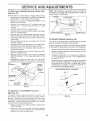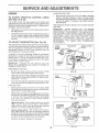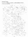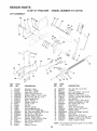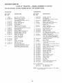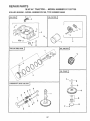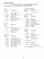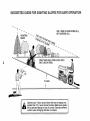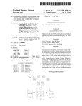
1
®
MODEL NUMBER 917.257730
OWNER'SMANUAL
o Assembly
Operation
Customer Responsibilities
Service and Adjustments
Repair Parts
CAUTION:
Read and follow
all safety
rules and instructions
before
operating
this equipment.
_j
SAFETY
Practices RULES
for Ride-On
Safe Operation
Mowers
&
IMPORTANT: THIS CUTTING MACHINE IS CAPABLE OF AMPUTATING HANDS AND FEETAND THROWING OBJECTS
FAILURE TO OBSERVE THE FOLLOWING SAFETY INSTRUCTIONS COULD RESULT IN SERIOUS INJURY OR DEATH
I.
GENERAL
,,
Read, understand_ and follow all instructions in the manual
and on the machine before starting.
Only allow responsible adults, who are familiar with the
instructions, to operate the machine.
Clear the area of objects such as rocks, toys, wire, etc.,
which could be picked up and thrown by the blade.
•
•
',
,,
"
•
"
,
,,
=
OPERATION
Be sure the area is clear of other people before mowing. Stop
machine if anyone enters the area.
Never carry passengers.
Do not mow in reverse unless absolutely necessary. Always
took down and behind before and while backing.
Be aware of the mower discharge direction and do not point
it at anyone. Do not operate the mower without either the
entire grass catcher or the guard in place.
Stow down before turning.
Never leave a running machine unattended. Always turn off
blades, set parking brake, stop engine, and remove keys
before dismounting.
Turn off blades when not mowing.
Stop engine before removing grass catcher or unclogging
chute.
"
=
Mow only in daylight or good artificial light.
Do net operate the machine while under the influence of
alcoho_ or drugs.
•
"
Watch for traffic when operating near or crossing roadways.
Use extra care when loading or unloading the machine into
a trailer or truck.
II.
SLOPE OPERATION
IlL CHILDREN
Tragic accidents can occur if the operator is not alert to th_
presence of children. Children are often attracted to the machine
and the mowing activity. Neverassume that children wilt remair
where you last saw them.
"
•
•
Before and when backing, look behind and down for smal
children.
,,
Never carry children. They may fall off and be seriously
iniured or interfere with safe machine operation.
Never allow children to operate the machine.
Use extra care when approaching blind corners, shrubs,
trees, or other objects that may obscure vision.
•
o
IV. SERVICE
"
•
"
Slopes are a major factor related to loss-of-control and tipover
accidents, which can result in severe injury or death. All slopes
require extra caution. If you cannot back up the slope or if you fee]
uneasy on it, do not mow it.
DO:
Mow up and down slopes, not across.
Remove obstacles such as rocks, tree timbs, etc.
Watch for holes, ruts, or bumps.
Uneven terrain could
overturn the machine. Tall grass can hide obstacles.
o
Use slow speed. Choose a low gear so that you will not have
to stop or shift while on the slope.
,,
Follow the manufacturer's
recommendations
for wheel
weights or counterweights to improve stability.
"
Use extra care with grass catchers or other attachments.
These can change the stability of the machine.
,,
Keep all movement on the slopes slowand gradual Do not
make sudden changes in speed or direction.
°
Avoid starting or stopping on a slope, tf tires lose traction,
disengage the blades and proceed slowly straight down the
slope.
DO NOT:
.
•
•
o
•
',
.
,
•
•
,,
Donotturnonsiopesuntessnecessary,andthen,turns_owiy
and gradually downhill, if possible.
Do not mow near drop-offs, ditches, or embankments. The
mower could suddenly turn over if a wheel is over the edge
of a cliff or ditch, or if an edge caves in.
Do not mow on wet grass. Reduced traction could cause
sliding.
Do not try to stabilize the machine by putting your foot on the
ground.
Do not use grass catcher on steep s_opes.
Keep children out of the mowing area and under the watchfu
care of another responsible adult.
Be alert and turn machine off if children enter the area.
,,
•
•
°
Use extra care in handling gasoline and other fuels. They are
flammable and vapors are explosive.
Use only an approved container.
Never remove gas cap or add fuel with the engine
running. Allow engine to coo! before refueling. Do not
smoke.
Never refuel the machine indoors.
Never store the machine or fuel container inside where
there is an open flame, such as a water heater.
Never run a machine inside a closed area.
Keep nuts and bolts, especially blade attachment bolts, tight
and keep equipment in good condition.
Never tamper with safety devices.
Check their proper
operation regularly.
Keep machine free of grass, leaves, or other debris build-up.
Clean oil or fuel spillage. Allow machine to cool before
storing.
Stop and inspect the equipment if you strike an object.
Repair, if necessary, before restarting.
Never make adjustments or repairs with the engine running.
Grass catcher components are subiect to wear, damage, and
deterioration, which could expose moving parts or allow
obiects to be thrown. Frequently check components and
replace with manufacturer's recommended parts, when necessary.
Mower blades are sharp and can cut. Wrap the blade(s) or
wear gloves, and use extra caution when servicing them.
Check brake operation frequently. Adjust and service as
required.
Look for this symbol to point out important safety precautions.
It means
CAUTION!!! BECOME ALERT!!! YOUR
SAFETY IS INVOLVED.
,,,,,I",',HH
I=
CAUTION:
Always
disconnect
spark
plug wire and place wire where it cannot
contact spark plug in order to prevent
accidental
starting
when
setting
up,
transporting,
adjusting
or making
repairs.
PRODUCT
CONGRATULATIONS
on your purchase of a Sears
Tractor. ft has been designed, engineered and manufactured to give you the best possible dependability and
performance.
Should you experience any problem you cannot easily
remedy, please contact your nearest Sears Authorized
Service Center/Department
Department. We have competent, welt-trained technicians and the proper tools to
service or repair this tractor.
Please read and retain this manual. The instructions will
enable you to assemble and maintain your tractor properly.
Always observe the "SAFETY RULES",
MODEL
NUMBER
SPECIRCAqT ONS
HORSEPOWER:
18.0
GASOLINE CAPACITY
AND TYPE:
3.5 GALLONS
UNLEADED REGULAR
OtL TYPE (APFSFiSG):
SAE 30 (above 32°F)
SAE 5W-30 (below 32°F)
OIL CAPACITY:
Wi FILTER:
W/O FILTER:
SPARK PLUG:
(GAP: .025")
CHAMPION
RV17YC
VALVE CLEARANCE:
INTAKE:
EXHAUST:
.003"-.006"
.003" - .0t6"
i
GROUND SPEED (MPH):
FORWARD:
REVERSE:
TIRE PRESSURE:
FRONT:
REAR:
0 - 5.6
0-2.5
.[
THE MODEL AND SERIAL NUMBERS WILL BE FOUND
ON A PLATE UNDER THE SEAT.
YOUSHOULDRECORDBQTHSERtALNUMBERAND
DATE OF PURCHASEAND
KEEPIN A SAFE PLACE
FOR FUTURE REFERENCE.
MAINTENANCE
is available on this prodstore for details.
the safety
Follow a regular schedule
using your tractor.
rules.
in maintaining,
CHARGING SYSTEM:
15 AMPS @ 3600 RPM
BLADE BOLT TORQUE:
30-35 FT_ LBS.
/
I
t
In the state of California the above is required by taw
(Section 4442 of the California Public Resources Code).
Other states may have similar laws. FederaJ _aws apply on
federal lands. A spark arrester for the muffter is available
through your nearest Sears Authorized Service Center/
Department (See REPAIR PARTS section ofthis manual)o
RESPONSIBILITES
Read and observe
!4 PSt
10 PSI
WARNING:
This tractor is equipped with an internal
combustion engine and should not be used on or near any
unimproved forest-covered, brush.-covered or grassocov ered land unless the engine's exhaust system is equipped
with a spark arrester meeting applicable _ocal or state laws
(if any), ff a spark arrester is used, it should be maintained
in effective working order by the operator.
AGREEMENT
A Sears Maintenance
Agreement
uct, Contact your nearest Sears
o
I
i
i
i
917.257730
DATE OF PURCHASE
•
--! '
4
SERIAL
NUMBER
CUSTOMER
4.0 P,NTS
-_
3.5 P_NTS
i
caring for and
Follow the instructions
under "Customer Responsibilities" and "Storage"
sections of this owneCs manual.
L|M TED TWO YEAR WARRANTY
ON ELECTR|C
START RIDING [email protected] P IENT
f
For two (2) years from the date of purchase, if this riding equipment is maintained, lubricated and tuned up according to the ;_
instructions in the owner's manual, Sears will repair or replace, free of charge, any parts found to be defective in material or I
workmanship.
This Warranty does not cover:
_'
Expendable items which become worn during norma_ use, such as blades, spark plugs, ai_ cleaners and belts.
Tire replacement or repair caused by punctures from outside objects, such as nails, thorns, stumps, or gtas&
Repairs necessary because of operator abuse, negligence, improper storage or accident or the faiture to maintain the
equipment according to the instructions contained in the owner's manual.
_
I
Riding equipment used for commercial or rental purposes.
1
LIM TED 90 DAY WARRANTY
ON BATTERY
i
For ninety (90) days from date of purchase, if any battery included with this riding equipment proves defective in material or
workmanship and our testing determines the battery wilt not hold a charge, Sears will replace the battery at no charcje
WARRANTY SERVICE
CENTER/DEPARTMENT
tS AVAILABLE BY RETURNING
IN THE UNITED STATES.
THE RIDING EQUIPMENT
TO THE NEAREST
SEARS SERVICE
This Warranty gives you specific legal rights, and you may also have other rights which may vary from state to state.
SEARS,
ROEBUCK
AND CO., D/817 WA, HOFFMAN
3
ESTATES,
ILLINOIS
60179
ii
!
1
TABLE OF CONTENTS
=
SAFETY
PRODUCT
RULES
............................................................
SPECIFICATIONS
MAINTENANCE SCHEDULE ......................................
SERVICE AND ADJUSTMENTS ............................ 20<
STORAGE ....................................................................
TROUBLESHOOTING ............................................
284
REPAIR PARTS - TRACTOR ................................. 3%_
REPAIR PARTS - ENGINE ..................................... 484
PARTS ORDERING/SERVICE ................ BACK COVE
2
......................................
3
CUSTOMER
RESPONSIBILITIES
..................... 3, 16=!9
WARRANTY
...................................................................
3
TRACTOR
ACCESSORIES
......................................
5,15
ASSEMBLY
..............................................................
7-10
OPERATION
...........................................................
11-15
INDEX
E
A
Accessories ......................................
5,15
Adjustments:
Brake ............................................
22
Carburetor .................................... 22
Clutch Pulley ................................ 22
Gauge Wheels .............................. 13
Mower
Front-To-Back ......................... 21
Side-To-Side ........................... 20
Throttle Control Cable .................. 26
Air Filter, Engine ..................................
18
Air Screen, Engine ............................... 18
Assembly ..........................................
7-10
Electrical:
Interlocks and Relays ................... 24
Schematic ..................................... 30
Wiring Diagram ............................. 32
Engine:
Air Filter ........................................
18
Air Screen ..................................... 18
Cooling Fins ................................. 18
Oi! Change ................................... 16
Oil Level .......................................
16
Oil Type ................................... 12,16
Preparation ................................... t4
Repair Parts ............................ 48-51
Starting .................................... 14-15
Storage ......................................... 27
Operation ........................................
11_1
Operating Mower ................................. I
Options:
Accessories ............................... 5,1
Spark Arrester ........................... 3,4
P
Parking Brake ......................................
1
Parts Bag ...............................................
Parts, ReplacemenVRepair ............ 3t-4
Product Specifications ........................... ;
R
Repair Parts ...................................
31-4:
B
Battery:
Charging .........................................
8
Cteaning .......................................
19
installation .................................... 10
Levels ........................................
8,17
Preparation ..................................... 8
Starting with Weak Battery ........... 24
Storage ......................................... 27
Terminals ......................................
18
Belt:
Motion Drive
RemovaVReptacement ............ 2t
Mower Drive
Removal/Replacement
............ 21
Mower Blade Drive
Remora!/Replacement
............ 22
Blade:
Sharpening ...................................
17
Replacement ................................ 17
Brake Adjustment ................................ 22
S
F
Filter:
Air Filter ........................................
Fuel ..............................................
Oil .................................................
Fuet:
Storage .........................................
Type .............................................
Fuse .....................................................
19
!9
19
27
14
24
H
Headlights ............................................
24
Hood RemovaVInstallation ................... 25
L
Leveling Mower Deck ..........................
Lubrication;
Chart .............................................
Engine ..........................................
20
14
!7
C
M
Carburetor Adjustment ........................ 26
Clutch Pulley ........................................
22
Controls, Tractor .................................. 11
Customer Responsibilities .............. 16-19
Engine:
Air Filter .................................... t 8
Air Screen ................................. 18
Cooling Fins ............................. 18
Engine Oil ............................ t4,18
Fuel Fitter ................................. 19
Spark Plug(s) ............................ 19
Tractor:
Battery ......................................
17
Blade ........................................
!7
Lubrication Chart ...................... 18
Maintenance Schedule ............. t 6
Tire Care .......................... 8,17,24
Transaxie .................................. 18
Maintenance Schedule ........................ 16
Mower:
Adjustment, Front-to-Back ............ 21
Adjustment, Side-to-Side .............. 20
Blade Replacement ...................... 17
Blade Sharpening ......................... 17
Cutting Height ............................... t 2
installation .................................... 20
Operation ......................................
13
Removal ....................................... 20
Mowing Tips ......................................... 15
Muffler ..................................................
19
Spark Arrester ........................... 3,40
Cutting Height, Mower .........................
12
O
Oi!:
Cold Weather Conditions ........ t 4,18
Engine ..........................................
16
Storage ......................................... 27
4
Safety Rules ..........................................
Seat ......................................................
Service and Adjustments ................ 20-2_
Carburetor ...................................
2_
Clutch Pulley ................................. 2_
Fuse .............................................
2z
Hood RemovaVInstallation ........... 2_
Motion Drive Belt
RemovaVReplacement ............ 2I
Mower Drive Belt
Removal/Replacement
............ 2t
Mower Blade Drive Belt
Removal/Replacement
............ 22
Mower Adjustment
Front-to-Back ........................... 21
Side-to-Side ............................. 20
Mower Removal/Installation ......... 20
Tire Care .............................. 8,15,24
Slope Guide Sheet ............................... 59
Spark Plug(s) .......................................
t9
Specifications ........................................
3
Starting the Engine ......................... 14-15
Steering Wheel ................................. 7,23
Stopping the Tractor ............................ 12
Storage ................................................
27
T
Throttle Control Cable Adiustment ....... 26
Tires .............................................
8,17,24
Troubleshooting Chart .................... 28-29
Transaxle .............................................
18
W
Warranty ................................................
Wiring Diagram ....................................
Wiring Schematic .................................
3
30
32
ACCESSORIES
These accessories
Most Sears stores
and attachments
can order these
AN
were available through most Sears retail outlets and service centers
items for you when you provide the model number of your tractor.
the tractor
was purchased,
MAINTENANCE
ENGRNE
SPARK
when
PLUG
GAS CAN
ENGINE OiL
FUEL STABiLiZER
S
\
PERFORMANCE
Sears offers a wide variety of attachments
that fit your tractor. Many of these are listed beiow with brief explanations
of how they can help
you. This list was current at the time of publication;
however,
it may change in future years - more attachments
may be added, changes
may be made in these attachments,
or some may no longer be available or fit your model.
Contact
your nearest
Sears store for the
accessories
and attachments
that are available for your tractor.
Most of these attachments
attaching
and detaching.
do not require
additional
hitches
or conversion
AERATOR promotes deep root growth for a healthy lawn, Tapered
2.5-inch steel spikes mounted on 10-inch diameter discs puncture
holes in soii at close intervals to tet moisture soak in. Steelweighttray
for increased penetration,
BUMPER
protects
front end of tractor
from damage,
SPREADERISEEDERS
make seeding, fertilizing, and weed killing
easy. Broadcast spreaders are also useful for granular de-icers and
sand.
SWEEPERS
easier, faster.
FRONT NOSE ROLLER canters in front of mower
chances of "scalping" on uneven terrain.
GANG HITCH lets you tow 2 or 3 pull-behind
attachments
at
once, such as sweepers,
dethatchers,
aerators (not for use with
rollers, carts or other heavy attachments).
thatch and
spring fine
forfront or
SPRING
thatch into
grass clippings
and leaves.
TIRE CHAINS are heavy duty; closely spaced
give smooth dde, outstanding
traction.
extra-large
cross tinks
TRACTOR CAB has heavy duty vinyl fabric over tubutar steel frame,
ABS plastic top; ctear plastic windshield offers 360 degree visibility,
Hinged metal doors with catch,
Keeps operator warm and dry.
Remove vinyl sides and windshields
for use as sun protector in
summer,
Optional
accessories
include:
tinted/tempered
solid
safety glass windshield with hand operated wiper; 12-volt amber
caution light for mounting on cab top.
PLOW turns soil 6 inches deep, cuts lO-inch furrow. Crank adjustment controls depth, 3-position yoke sets width. Heavy steel landside
for straight furrowing.
(Requires sleeve hitch,)
RAtVIP TOPS AND FEET let you ioad and unioad tractor
pickup truck. Use with 2 x 8 or2 x !0 tumber.
let you collect
TILLER has 8 hp engine to prepare seed beds, cultivate, and compost
garden residue, Chain-drive transmission,
Six 114nch diameter one
piece heat-treated steel tines. TiIIs 30-inch path. (Requires sleeve
hitch.) Or use 5 hp tow-behind TILLER with 36-inch swath to prepare
seed beds, cultivate and compost garden residue. Tiller has its own
built-in lift and depth control system and does NOT require a sleeve
hitch. Fits any lawn, yard or garden tractor. Simply hook up to the
tractor drawbar and go! Optional accessories
for 5 hp tiller convert
unit for dethatching, aerating, hiIling...without
tools.
deck to reduce
MULCH RAKEiDETHATCHER
loosens soil and flips
matted leaves to lawn surface for easy pickup. Twenty
teeth. Useful toprepare bare areasforseeding,
Available
rear mounting.
H_GH PERFORMANCE
REEL-ACTiON
T1NE DETHATCH ER covers 36-inch wide path and tosses
large hopper. Mounts behind tractor.
Single pin couples/
SPRAYERS
use 12-volt DC electric motor that connects to the tractor
battery or other 12-volt source.
Includes
booms for automatic
spraying and hand held wand forspot spraying. Wand has adjustable
spray pattern. For applying herbicides, insecticides, fungicides and
liquid fertilizers.
dirt, sand and gravel, 48
path when angled. Master
trip for snow removai on
to foIlow ground contour.
with tire chains and wheel
makes oil changes
for easy
SNOWTHROWER
has 42-inch swath.
Drum-type
auger handles
powdery and wet/heavy snow_ Mounts easily with simple pin arrangement, Discharge chute adjusts Irom tractor seat. 6-inch diameter
sioout discharges snow 10 to 50 feet, Lift controlled at tractor seat.
(Use with chains and wheel weights and/or rear drawbar weight.)
DiSC HARROW has 2 gangs of 4 steel blades that angle from 10 to
20 degrees, 40 inches wide. Can hook 2 units in tandem. (Requires
sleeve hitch.)
VALVE
and are designed
SLEEVE H_TCH for use wilh master lift system,
uncouples.
CORING AERATOR takes small plugs out of soil to allow moisture
and nutrientsto reach grass roots. 36-inch swath. 24 hardened steel
coring tips, t50 Ib, capacity weight tray.
EASY OiL DRAIN
that do are indicated)
SLEEVE CULTIVATOR
is 43 inches wide. Prepares
ground for
seeding, helps weed control. Steel frame holds 5 adjustable sweeps,
Adjusts vertically, horizontally.
(Requires sleeve hitch.) Optional
accessory:
steel furrow opener for wider openings for potatoes,
corn, and other deep-seeded
crops.
CARTS make hauling easy, Variety of sizes available, plus accesso*
des such as side panel kits, tool caddy, cart cover, protective mat and
dolly,
DOZER BLADE removes snow; grades
inches wide, 17 inches high, clears 44-inch
lift control lever for operator ease. Spring
uneven pavement; built-in float for blade
Reversible, reptaceabIe scraper bar. (Use
weights and/or rear drawbar weight.)
kits (those
from a
R EAR GRADE R BLADE is 42 inches wide and operated from driver's
seat. Reversible steel blade can be angled at 30 degrees for grading.
Reverses for pushing snow backwards.
(Requires sfeeve hitch.)
VACS for powerful collection of heavy grass clippings and leaves.
Optiona_ wand attachment
to pick up debris in hard-to-reach
places.
VAC/CH_PPER
includes a chipper-shredder.
ROLLER for smoother Iawn surface. 36-inch wide, 18qnch diameter
water-tight drum holds up to 390 Ibs. of weight.
Rounded edges
prevent harm to turf. Adjustable scraper automatically
cIeans drum.
WEIGHT BRACKET for drawbar for snow removal applications.
Can
be mounted on front of tractor for plowing applications.
Uses (1) 55
lb. weight.
WH EEL WEIGHTS for rear wheets provide
removal or dozing heavy materials,
5
needed traction
for snow
CONTENTS
Parts Bag contents
OF HARDWARE
shown futl size
PACK
Parts packed
separateJy
Jn carton
O
Seat
Battery acid
(!) Shoulder Bolt 5/16-18
(1) Knob
Battery
I
Steering Wheel
I
F
E
(1) Washer
_
17/32 x 1-3/16 x 12 Gauge
Parts Bag
Owner's
Manual
(3) Retainer Springs
_2w_
_u,_e
,_ ._,_'_
_//
(4) Retainer
_2)
Front Link Assemblies
(2) Battery Carriage Bolts 1/4-20 x 7-1/2
ii
,."-'%.
_I
i,/"-_,
ii _
(2) Keys
!
' .
Termina! Guard
Steering Wheet Insert
9/32 x 5/8 x 16 Ga.
\
(2) Lock Washers
{C_
(2) Crown
Lock Nuts
(2) Shoulder Bolts
(2) Hex Nuts 1/4-20
(2) Washers
Steering
Steeve
(2) Washers
3/8 x 3/4 x 14 Gauge
Springs
@
(2) Hex Bolts I/4-20 x 3/4
(_'_l
r
1/4
%
.........
[
f
}i
J
z
(2) Wing Nuts 1/4-20
15° Slope Sheet
Battery Caps
and Instructions
ASS
LY
Your new tractor has been assembled at the factory with exception of those parts left unassembled for shipping purposes.
To ensure safe and proper operation of your tractor al! parts and hardware you assemble must be tightened securely. Use
the correct tools as necessary to insure proper tightness,
TOOLS
REQUmRED FOR ASSEMBLY
STEERING
A socket wrench set wilI make assembly easier. Standard
wrench sizes are listed.
(2) 7/16" wrenches
(1) Tire pressure gauge
(1) 9/16" wrench
(1) Utility knife
(1) 1/2" wrench
(1) 3/4" socket w/drive ratchet
_
UNPACK
INSERT
LOC,
¢,
-T
When right or left hand is mentioned in this manual, it
means when you are in the operating position (seated
behind the steering wheel).
TO REMOVE TRACTOR
STEERING
WHEEL
FROM CARTON
CARTON
,
Remove all accessible loose parts and parts cartons
from carton (See page 6).
•
Cut, from top to bottom, along lines on al! four corners
of carton, and lay panels flat,
STEERING
WHEEL
ADAPTER
STEERING
SLEEVE
Remove mower and packing materials.
Check for any additional loose parts or cartons and
remove.
BEFORE ROLLING TRACTOR OFF SKiD
ATTACH
STEERING
WHEEL
FIG, t
(See Fig. 1)
o
Remove hex bolt, lock washer and large flat washer
from steering shaft.
,
Position front wheels of the tractor so they are pointing
straight forward.
,
Slide steering sleeve over steering shaft.
,
Position steering wheel so cross bars are horizontal
(left to right) and slide onto steering wheel adapter.
•
Secure steering wheel to steering shaft with hex bolt,
lock washer and large flat washer previously removed.
Tighten securely.
Snap steering wheel insert into center of steering
wheel.
Remove protective plastic from tractor hood and grill.
IMPORTANT: CHECK FOR AND REMOVE ANY STAPLES
iN SKID THAT MAY PU NCTU RE TI RES WHERE TRACTOR
IS TO ROLL OFF SKID.
TO ROLL TRACTOR
OFF SKID (See Fig. 7)
•
Raise attachment lift lever to its highest position.
,
Release parking brake by depressing clutch/brake
pedal.
Place freewheel control in freewheeling position to
disengage transmission (See "TO TRANSPORT" in
Operation section of this manual),
Rolt tractor backwards off skid.
o
-
WHEEL
7
_ HEX BOLT
WASHER
FLAT
ASSEMBLY
HOW TO SET UP YOUR TRACTOR
PREPARE
BATTERY
iNSTALL
SEAT (See Fig, 3)
Adjust seat before tightening adjustment knob.
(See Fig. 2}
Remove cardboard packing on seat pan.
o
CAUTION: Wear eye and face shield.
Place seat on seat pan and assemble shoulder bolt,
Assemble adjustment knob and flat washer loosely.
Do not tighten.
Wash hands or clothing immediately if
accidentally in contact with battery acid,
Do not smoke. Fumes from charged
battery acid are explosive.
o
Tighten shoulder bolt securely.
o
Lower seat into operating position and sit on seat.
Slide seat until a comfortable position is reached which
allows you to press clutch/brake pedal all the way
down.
Read the instructions included with the
battery vent caps. Always wear gloves,
clothing and goggles to protect your
hands, skin and eyes.
o
Get off seat without moving its adjusted position.
o
Raise seat and tighten adjustment knob securely.
Your tractor has a battery charging system which is
sufficient for normal use. However, periodic charging of the
battery with an automotive charger will extend its life.
o
See instructions packed with vent caps in parts bag.
*
Fill battery with acid. Fill each cell until it reaches the
bottom of the vent wells. Do not oveffitl.
.
Allow battery to stand and settle for at least thirty
minutes. After standing, check the battery cell acid
level, tf below the vent wells, add more acid until the
correct level is reached.
SEAT
SEAT
SHOULDER
BOLT
While battery is standing (after adding acid) and later, while
battery Jsbeing charged, continue with assembly of tractor.
IMPORTANT:
TO MAXIMIZE THE LIFE OF YOUR
BATTERY,
1T IS NECESSARY THAT THE BATTERY BE
CHARGED BEFORE USE. FAILURE TO CHARGE
BATTERY CAN RESULT IN A SHORTENED BATTERY
LIFE.
o
Charge battery at a rate of 6 amperes for 1 hour. Use
a 12 vott battery charger. Observe all safety precautions required for battery charging.
•
Check the acid level after the battery is charged. If the
acid has fallen below the correct level, add distilled oriron free water.
Check battery case for leakage to make sure that no
damage has occurred in handling.
o
Dispose of excess battery acid. Neutralize acid for
disposal by adding it to two gallons of water in a five
gallon plastic container. Stir with a wooden or plastic
paddle while adding baking soda until the addition of
more soda causes no more foaming.
o
FLAT
WASHER
ADJUSTMENT
KNOB
FIG. 3
CHECK TIRE PRESSURE
The tires on your tractor were overinflated at the factory for
shipping purposes. Correct tire pressure is important for
best cutting performance.
install the vent caps to cover the vent wells. Wash the
top of the battery with water to remove any acid, then
wipe dry.
=
PAN
Reduce tire pressure to PSi shown in "PRODUCT
SPECIFICATIONS" on page 3 of this manual
CHECK
BRAKE
SYSTEM
After you learn how to operate your tractor, check to see
that the brake is properly adjusted. See "TO ADJUST
BRAKE" in the Service and Adjustments section of this
manual.
Follow instructions on how to install baltery.
FiG. 2
8
ASSEMBLY
o
_NSTALL MOWER
AND ORmVE BELT
(See Figs. 4 and 7)
Be sure tractor is on level surface. Engage parking brake.
*
Cut and remove tie down securing anti-sway bar.
Swing anti-sway bar to left side of mower deck.
,
Relieve idler tension from belt. Push idter forward and
place a b!ock (standard wood 2 x 4 or equivalent)
behind idler pulley.
= Slide mower under tractor with discharge guard to right
side of tractor.
Swing L.H. gauge wheel bar forward by removing rear
retainer spring and pin.
,
install one front link in top hole of the L.H. front mower
bracket and L.H. front suspension bracket. Retain with
two single loop retainer springs as shown.
Slide right side of mower deck forward, toward R.H.
front tire.
IMPORTANT: CHECK BELT FOR PROPER ROUTING IN
ALL MOWER PULLEY GROOVES. iNSTALL BELT INTO
ELECTRIC CLUTCH PULLEY GROOVE.
,
=
,
,
Install second front link in the top hole of the R.H. front
mower bracket and R.H. front suspension bracket.
Retain with two singEe loop retainer springs as shown.
Carefully remove btock from behind idler pulley.
Turn height adjustment knob counterclockwise until it
stops.
Lower mower linkage with attachment lift lever.
,
o
o
o
,,
Place the suspension arms on inward pointing deck
pins. if necessary, rock and raise front of mower to
align deck pins with the hopes in suspension arms.
Retain with double loop retainer springs.
Connect anti-sway bar to chassis bracket under left
footrest and retain with double !cop retainer spring.
Turn height adjustment knob clockwise to remove
slack from mower suspension.
Raise deck to highest position.
Swing L.H. gauge wheel bar back towards rear of
mower and secure with pin and retainer spring removed earlier.
Assemble gauge wheels as shown using long shoulder
bolts, 3/8 washers and 3/8-I 6 center Iocknuts. Tighten
securely.
Adjustgaugewheetsbeforeoperating
mowerasshown
in the Operation section of this manual.
CHECK
DECK LEVELNESS
For best cutting results, mower housing should be properly
leveled. See "TO LEVEL MOWER HOUSING" in the
Service and Adjustments section of this manual.
CHECK
BELTS
FOR
PROPER
FRONT
LINKS
L.H. GAUGE
WHEEL BAR
SHOULDER
BOLT
GAUGE
WHEEL
ANTI-SWAY
BAR
3/8 WASHER
IDLER "/
/
38-16
CENTER
LOCKNUT
PULLEY
/
/
BLOCK
(Wood 2 x 4 or equiv.)
///
DmSCHARGE'__
GUARD
FIG. 4
ALL
FRONT
SUSPENSION
BRACKETS
DOUBLE LOOP
RETAINER SPRING
(inward pointing
deck pins)
DOUBLE LOOP
RETAINER SPRING
OF
See the figures that are shown for replacing motion, mower
drive, and mower blade drive belts in the Service and
Adjustments section of this manual. Verify that the belts are
routed correctly.
SUSPENSION
ARMS
CHASSIS
BRACKET
POSITION
t; /
' I
ASSEMBLY
INSTALL
BATTERY
(See Figs. 5 and 6)
TERMINAL
CAUTION: Do not short battery terminals. Before installing battery, remove
_
TERMINAL
rings, etco
etal bracelets, wristwatch
bands,
Positive terminsI must be connected
first to prevent sparking from accidental grounding.
BATTERY
DOORS
I
PENT CAPS
BATTERY
•
Lift hood to raised position.
-
Be sure battery drain tube has not come loose and is
securely attached to drain in battery tray.
•
Lower battery into battery tray with terminals to front of
tractor.
,
First connect RED battery cable to positive (+) battery
terminal with hex bolt, flat washe r, lock washer and hex
nut as shown. Tighten securely.
TRAY
KEY HOLE
FiG. 6
7CHECKLIST
BEFORE YOU OPERATE AND ENJOY YOUR NEW
TRACTOR, WE WISH TO ASSURE THAT YOU RECEIVE
THE BESTPERFORMANCEAND
SATISFACTION FROM
THIS QUALITY PRODUCT.
o
Connect BLACK grounding cable to negative (-) battery
terminat with remaining hex bolt, flat washer, lock
washer and he× nut. Tighten securely.
•
Stide the two battery bolts through the terminal guard
and start the wing nuts onto the threads.
,/
All assembly instructions have been completed.
Position terminal guard over battery as shown, lower
battery bolts into key holes and slide square shafts of
battery bolts into slots of key holes.
,/
No remaining loose parts in carton.
¢'
Batteryis properly prepared and charged.
1 hour at 6 amps).
,/
Seat is adjusted comfortably and tightened securely.
,
PLEASE REVIEW THE FOLLOWING CHECKLIST,"
Tighten wing nuts by hand making sure battery bolts
remain in sJots of the key holes in the battery supporL
Be sure terminal access doors are closed.
¢" All tires are properly inflated. (For shipping purposes,
the tires were overinflated at the factory).
Use terminal access doors for:
,
inspection
ware).
for secure connections
,
inspection for corrosion.
o
Testing battery.
,/
Be sure mower deck is properly leveled side-to-side/
front-to-rear for best cutting results. (Tires must be
properly inflated for leveling).
v"
Check mower and drive belts. Be sure they are routed
property around pulleys and inside all belt keepers.
v"
Check wiring. See that all connections are still secure
and wires are properly clamped.
(to tighten hard-
JumpJng (if required).
,
(Minimum
v'
Before driving tractor, be sure freewheel controi is in
drive position.
WHILE LEARNING HOWTO USE YOUR TRACTOR, PAY
EXTRA A TTENTION TO THE FOLL OWING IMPORTANT
ITEMS:
Periodic charging.
,/
Engine oil is at proper level.
v"
Fuel tank is filled with fresh, clean, regular unleaded
gasoline.
Become familiar with all controls - their location and
function. Operate them before you start the engine.
•/
F3G. 5
I0
v"
Be sure brake system is in safe operating condition.
7
It is important to purge the transmission before operating your tractor for the first time. Fotlow proper starting
and transmission purging instructions (See "TO START
ENGINE" and "PURGE TRANSMISSION" in Operation section of this manual).
OPERATION
......
=
KNOW YOUR TRACTOR
READ THIS OWNER'S
MANUAL
AND SAFETY
RULES
BEFORE
OPERATING
YOUR TRACTOR.
Compare the i!lustrations with your tractor to familiarize yourself with the location of various controts and adjustments. Save
this manual for future reference.
THROTTLE
AMMETER
CONTROL
ATTACHMENT
CLUTCH SWITCH
CHOKE CONTROL
LIGHT SWITCH
CLUTCNtBRAKE
PEDAL
iGNiTION
HEIGHT ADJUSTMENT
KNOB
l
PARKING BRAKE
LEVER
MOTION
CONTROL
LEVER
APPROX.
SPEEDS:
FREE WHEEL
SWITCH
CONTROL
FIG, 7
Our tractors conform to the safety standards of the American National Standards institute,
ATTACHMENTCLUTCH
SW_TCH - Used to engage mower
blades or other attachments mounted to your tractor.
UFT LEVER- Used to raise and lower mower deck or other
attachments mounted to your tractor.
THROTTLE CONTROL - Used to control engine speed.
CLUTCH/BRAKE
PEDAL - Used for declutching
braking the tractor and starting the engine.
AMMETER - indicates battery charging (+) or discharging
FREEWHEEL CONTROL - Disengages transmission for
pushing or stowly towing the tractor with the engine off.
tGNITmON SWITCH - Used to start and stop the engine.
and
(-).
MOT1ON CONTROL _ Selects the speed and direction ol
tractor.
CHOKE CONTROL - Used when starting a cold engine.
LIGHT SW_TCH - Turns the headlights on and off,
PARKING BRAKE LEVER - Locks clutch/brake pedal into
the brake position.
NE_GHTADJUSTMENT
height,
11
KNOB- Used to adjust the mower
OPERATION
the spectacles
or standard
safety g_asses.
HOW "TO USE YOUR TRACTOR
TO SET PARKING
BRAKE
o
Never use choke to stop engine.
NOTE: Under certain conditions when unit is standing idte
with the engine running, hot engine exhaust gases may
cause "browning" of grass_ To eliminate this possibility,
always stop engine when stopping tractor on grass areas.
(See Fig. 8)
Your tractor is equipped with an operator presence sensing
switch. When engine is running, any attempt by the
operator to teave the seat without first setting the parking
brake will shut off the engine.
o Depress clutch/brake pedal into fult "BRAKE" position
and hold.
•
Place parking brake lever in"ENGAGED" position and
release pressure from clutch/brake pedal. Pedal should
remain in "BRAKE" position. Make sure parking brake
will hold tractor secure.
THROTTLE
CONTROL LEVER
"DISENGAGED"
POSITION
pletely, as described above, before leavCAUTION:
ing the operator's
Atways position;
stop tractor
to empty
comgrass catcher, etc.
TO USE CHOKE
ATTACHMENT
CLUTCH
SWITCH
"ENGAGED"
POSITION
CHOKE
CONTROL
CONTROL
TO USE THROTTLE
TO MOVE FORWARD
(See Fig. 8)
(See Fig. 8)
,,
HEIGHT
ADJUSTMENT
KNOB
"DISENGAGED
POSITION
....
•
PARKING
BRAKE
ENGAGED"
POSITION
Start tractor with motion control lever in neutral (N)
position.
Release parking brake and clutch/brake pedal.
Slowly move motion control lever to desired position.
TO ADJUST MOWER
(See Fig. 9)
FiG. 8
CUTTING
HEIGHT
The cutting height is controlled by turning the height adjustment knob in desired direction.
o Turn knob clockwise (/-_) to raise cutting height.
o Turn knob counterclockwise (F_) to lower cutting
height.
The cutting height range is approximately 1-1/4" to 4-1/4%
The heights are measured from the ground to the blade tip
with the engine not running. These heights are approximate and may vary depending upon soil conditions, height
of grass and types of grass being mowed.
o The average lawn should be cut to approximately 2-1/2
inches during the coo! season and to over 3 inches
during hot months. For healthier and better looking
lawns, mow often and after moderate growth.
For best cutting performance, grass over 6 inches in
height should be mowed twice. Make the first cut
relatively high; the second to desired height.
(See Fig, 8)
MOWER BLADES ,
Move attachment clutch switch to "DISENGAGED"
position.
GROUND DRIVE o Depress clutch/brake pedal into full "BRAKE" position.
•
Move motion control lever to neutra_ (N) position.
IMPORTANT:
THE MOTION CONTROL LEVER DOES
NOT RETURN TO NEUTRAL (N) POSITION WHEN THE
CLUTCH/BRAKE PEDAL tS DEPRESSED
ENGINE Move throttle control to slow (,,_,) position.
NOTE: Failure to move throttle control to slow (4_)
position and allowing engine to idte before stopping may
cause engine to "backfire".
Turn ignition key to "OFF" position and remove key.
Always remove key when leaving tractor to prevent
unauthorized use.
AND BACKWARD
The direction and speed of movement is controlled by the
motion control lever.
MOTmON
CONTROL
LEVER
STOPPING
CONTROL
Always operate engine at full throttle.
Operating engine at less than fuIl throttle reduces the
battery charging rate.
,_ Full throttle offers the best bagging and mower performance.
CLUTCH]BRAKE
PEDAL "BRAKE"
POSITION
"DR_VE"
POSiTiON
(See Fig. 8)
Use choke control whenever you are starting a cofd engine.
Do not use to start a warm engine.
o To engage choke control, putl knob out, Stowly push
knob in to disengage.
t2
OPERATION
TO ADJUST
GAUGE
WHEELS
o
•
Adjust mower to desired cutting height.
Lower mower with lift control. Remove rear retainer
spring and clevis pin which secure each gauge wheel.
o
Lower gauge wheels to ground. Raise gauge wheels
slightly to align holes in bracket and gauge wheel bar
and insert clevis pins. Gauge wheels should be slightly
off the ground.
-
TO OPERATE
(See Fig. 9)
CAUTION:
Do not drive up or down
hills with slopes greater than 15 ° and
do not drive across any slope.
o
Choose the slowest speed before starting up or down
hifis.
o
o
Avoid stopping or changing speed on hills.
tf slowing is necessary, move throttle control lever to
slower position,
o If stopping is absolutely necessary, push clutch/brake
pedal quickly to brake position and engage parking
brake.
,
Move motion control lever to neutral (N) position.
iMPORTANT:
THE MOTION CONTROL LEVER DOES
NOT RETURN TO NEUTRAL (N) POSITION WHEN THE
CLUTCH/BRAKE PEDAL IS DEPRESSED.
o To restart movement, slowly release parking brake and
clutch/brake pedal.
Slowly move motion control lever to slowest setting.
o Make all turns slowly.
Replace retainer springs into clevis pins.
RETAINER
SPRING
ON HILLS
_
CLEVIS
GAUGE
WHEEL BAR
GAUGE
WHEEL
TO TRANSPORT
TO OPERATE
MOWER
When pushing or towing your tractor, be sure to disengage
transmission by placing freewheel control in freewheeling
position. Free wheel control is located at the rear drawbar
of tractor.
(See Figs. 7 and 8)
-
Your tractor is equipped with an operator presence sensing switch. Any attempt by the operator to leave the seat
with the engine running and the attachment clutch engaged
will shut off the engine.
,
=
Select desired height of cut.
Lower mower with attachment lift control.
•
Start mower blades by engaging attachment
control.
Raise attachment !ifl to highest position with attachment lift control,
Remove retainer spring from freewheel control rod,
clutch
°
Push control rod in to disengage transmission and
reinsert retainer spring into control rod hole now on
back side of the bracket.
•
Do not push or tow tractor at more than two (2) MPH.
•
To reengagetransmission,
reverse above procedure.
NOTE: To protect hood from damage when transporting
you rtractor on a truck or a traiter, be sure hood is closed and
secured to tractor. Use an appropriate means of tying hood
to tractor (rope, cord, etc.),
TO STOP MOWER BLADES - disengage attachment
clutch control.
l&
(See Figs, 7 and 1t)
without either the entire grass catcher,
on mowers so equipped, or the disAUTION:
operate the mower
charge
guardDoinnot
place.
\
RUNNER
DISCHARGE
GUARD
RGo 10
t3
F_G. 11
OPERATION
BEFORE
CHECK
,
o
-
TO START
$TARTmNG THE ENGINE
ENGINE
ENG|NE (See Fig. 8)
When starting engine for the first time or if engine has run
out of fuel, it will take extra cranking time to move fuel from
the tank to the engine.
OIL LEVEL (See Fig. !2)
The engine in your tractor has been shipped, from the
factory, already rifted with summer weight oil.
Check engine oil with tractor on level ground.
Remove oil fill cap/dipstick and wipe clean, reinsert the
dipstick and push it all the way down into the tube, wait
for a few seconds, remove and read oil level. If
necessary, add oil until "FULL" mark on dipstick is
reached. Do not overfill
For cold weather operation you should change oil for
easier starting (See "OIL VISCOSITY CHART" in the
Customer Responsibilities section of this manual).
To change engine oil, see the Customer Responsibilities section in this manua!.
-
Depress clutch!brake pedal and set parking brake.
,
Place motion control lever in neutral (N) position.
•
Move attachment clutch to "DISENGAGED"
,
Pull choke control out to choke (IX1) position for cold
engine start. For warm engine start do not use choke
control
position.
Move throttle control to midway between fast (,t_) and
slow (,_) positions.
-
insert key into ignition and turn key clockwise to"START"
position and release key as soon as engine starts. Do
not run starter continuously for more than fifteen
seconds per minute, if engine does not start after
several attempts, move throttle control to fast (,t_)
position, wait a few minutes and try again.
,,
When engine starts, slowly push choke control in.
Move throttle control to fast (,_) position.
Allow engine to warm up for a few minutes before
engaging drive or attachments.
IMPORTANT: COLD STARTING FOR HYDRO (BELOW
40°F) - AFTER STARTING ENGINE AND BEFORE
DRIVING,
TRANSMISSION
WARM UPLEVER
FOR (It)N
MINUTE BYLET
PLACING
MOTION CONTROL
NEUTRAL AND RELEASING CLUTCH/BRAKE PEDAL,
F{Go I2
ADD
NOTE: If at a high altitude (above 3000 feet) or in cold
temperatures (below 32°F), the carburetor fuel mixture
may need to be adjusted for best engine performance. See
"TO ADJUST CARBURETOR" in the Service and Adjustments section of this manual.
GASOLINE
*
FIll fuel tank. Use fresh, clean, regular unleaded
gasoline. (Use of leaded gasoline will increase carbon
and lead oxide deposits and reduce valve _ife).
IMPORTANT: WHEN OPERATING IN TEMPERATURES
BELOW 32°F(0°C), USE FRESH, CLEAN WINTER GRADE
GASOLINE TO HELP iNSURE GOOD COLD WEATHERSTARTING.
WARNING:
Experience indicates that alcohol blended
fuels (called gasohoi or using ethanol or methanol) can
attract moisture ,which leads to separation and formation of
acids during storage. Acidic gas can damage the fue!
system of an engine while in storage. To avoid engine
problems, the fuel system should be emptied before storage of 30 days or longer. Drain the gas tank, start the
engine and let it run untit the fuel lines and carburetor are
empty. Use fresh fuel next season, See Storage Instructions for additional information.
Never use engine or
carburetor cleaner products in the fuel tank or permanent
damage may occur.
filler neck. Do not overfill Wipe off any
spil_led
CAUTION:
oil or FiJl
fuel,to Co
bottom
not store,
of gas
spi_
tank
or
use gasoline near an open flameo
14
OPERATION
MOWING
PURGE TRANSMISSION
T PS
Tire chains cannot be used when the mower housing
is attached to tractor.
o
To ensure proper operation and performance, it is recommended that the transmission be purged before operating
tractor for the first time. This procedure will remove any
trapped air inside the transmission which may have developed during shipping of your tractor.
IMPORTANT: SHOULD YOURTRANSMISSION REQUIRE
REMOVAL FOR SERVICE OR REPLACEMENT,
IT
SHOULD BE PURGED AFTER REINSTALLATION
BEFORE OPERATING THE TRACTOR.
o
Place tractor safely on level surface with engine off and
parking brake set.
•
Disengage transmission by placing freewheel control
in freewheeling position (See "TO TRANSPORT" in
this section of manual).
o
Sitting in the tractor seat, start engine. After the engine
is running, move throttle control to slow (_)
position.
With motion control lever in neutral (N) position, slowly
disengage clutch/brake pedal.
o
Move motion control lever to full forward position and
hold for five (5) seconds. Move lever to full reverse
position and hold for five (5) seconds. Repeat this
procedure three (3) times.
o
o
o
o
o
NOTE: During this procedure there will be no movement of
drive wheels, The air is being removed from hydraulic drive
system.
Move motion control lever to neutral (N) position. Shutoff engine and set parking brake.
o
Mower should be properly leveled for best mowing
peflormance. See"TO LEVEL MOWER HOUSING" in
the Service and Adjustments section of this manual.
Use the runner on the right hand side of mower as a
guide. The blade cuts approximately an inch outside
the runner (See Fig. 10).
The left hand side of mower shouid be used for trimming.
Drive so that clippings are discharged onto the area
that has been cut. Have the cut area to the right of the
tractor. This will result in a more even distribution of
clippings and more uniform cutting.
When mowing large areas, start by turning to the right
so that clippings wilt discharge away from shrubs,
fences, driveways, etc. After one or two rounds, mow
in the opposite direction making left hand turns until
finished (See Fig. !3).
If grass is extremely tall, it should be mowed twice to
reduce load and possible fire hazard from dried clippings. Make first cut relatively high; the second to the
desired height.
Do not mow grass when it is wet. Wet grass will plug
mower and leave undesirable clumps. Allow grass to
dry before mowing.
Always operate engine at ful! throttle when mowing to
assure better mowing performance and proper discharge of material. Regulate ground speed by selecting a low enough gear to give the mower cutting
performance as well as the quality of cut desired.
When operating attachments, select a ground speed
that will suit the terrain and give best performance of
the attachment being used.
Engage transmission by placing freewheel control in
driving position (See '_ro TRANSPORT" in this section
of manual).
o
Sitting in the tractor seat, start engine. After the engine
is running, move throttle control to half (1/2) speed.
With motion control lever in neutral (N) position, slowly
disengage clutch/brake pedal.
,
Slowly move motion control lever forward, after the
tractor moves approximately five (5) feet, slowly move
motion control lever to reverse position. After the
tractor moves approximately five (5) feet return the
motion control lever tothe neutral (N) position, Repeat
this procedure with the motion control lever three (3)
times.
o
Your tractor is now purged and now ready for normal
operation.
FIG. 13
15
RESPONSIBILITIES
4q--
I
N
i
1 _Change more oftenwhen operatingunder a hear _loado_ inhighambient temperatures,
2 - Servicemore oftenwl_enope_'ating
indirtyor dustyconditions.
3 - Ifequipped
GENERAL
with oi_filtefl
change
oilevery 50 hours,
4. Replace blades more often when mowing in sandy soil
5 -IIequipped with ediustable system
6 Not required if equipped wltlt maintenance-free battery,
RECO_,_MENDATIONS
LUBRICATION
The warranty on this tractor does not cover items that have
been subjected to operator abuse or negligence.
To
receive full value from the warranty, operator must maintain
tractor as instructed in this manual.
t_TIE
Some adjustments witt need to be made periodically to
properly maintain your tractor.
o
FRONT WHEEL(_)
L._J_
Once a year you should replace the spark plug, clean
or replace air filter, and check blades and belts for
wear. A new spark plug and clean air filter assure
proper air-fuel mixture and hetp your engine run better
and last longer.
EACH
ROD BALL JOINTS
(_ FRONT WHEEL--_,,__._.:_:5!'_
Ait adjustments in the Service and Adjustments section of
this manual should be checked at least once each season.
BEFORE
CHART
_-LEJ
_-
SECTOR GEAR
TEETH
ENGINE (_
USE
Check engine oil leve!.
Check brake operation.
o
Check tire pressure.
Check for loose fasteners.
SPRAY SILICONE
IMPORTANT:
DO NOT OIL OR GREASE THE PIVOT POINTS
WHICH HAVE SPECIAL NYLON BEARINGS.
VISCOUS LUBRtCANTS WILL ATTRACT
BUST AND DIRT THAT WILL SHORTEN
THE LIFE OF THE SELF-LUBRICATING
BEARINGS.
IF YOU
FEEL. THEY MUST BE LUBRICATED,
USE ONLY A DRY, POWDERED GRAPHITE
TYPE LUBRICANT
SPARINGLY.
GENERAL
LUBRICANT
BOOTS TO LUBRICATE)
PURPOSE GREASE
(_) REFER TO CUSTOMER
t6
(_OVE
RESPONSIBILtTIE!S
"ENGINE"
SECTION
CUSTOMER
RESPONSJ
ES
TRACTOR
TO SHARPEN
Always observe safety rules when performing any maintenance.
Care should be taken to keep the blade balanced. An
unbalanced blade will cause excessive vibration and even-tun! damage to mower and engine.
BRAKE
•
The blade can be sharpened with a fife or on a grinding
wheel. Do not attempt to sharpen while on the mower.
o
To check blade balance, you will need a 5/8" diameter
steel bolt, pin, or a cone balancer. (When using a cone
balancer, follow the instructions supplied with balancer).
OPERATION
If tractor requires more than six (6) feet stopping distance
at high speed in highest gear, then brake must be adjusted.
(See "TO ADJUST BRAKE" in the Service and Adjustments section of this manual).
TIRES
,
Maintain proper air pressure in all tires (See "PRODUCT SPECIFICATIONS" on page 3 of this manual).
o
Keep tires free of gasoline, oi!, or insect control chemicals which can harm rubber.
•
Avoid stumps, stones, deep ruts, sharp objects and
other hazards that may cause tire damage.
BLADE
{See Fig° 15)
Slide blade on to an unthreaded portion of the steel bolt
or pin and hold the bo!t or pin parallel with the ground.
If blade is balanced, it should remain in a horizontal
position, if either end of the blade moves downward,
sharpen the heavy end until the blade is balanced.
NOTE: Do not use a nait for balancing blade. The lobes of
the center hole may appear to be centered, but are not.
CENTER HOLE
BLADE
For best results mower blades must be kept sharp.
place bent or damaged blades.
BLADE
=
]
CARE
REMOVAL
Re-
(See Fig. 14)
518"BOLT
Raise mower to highest position to allow access to
btades.
BLADE
OR PIN
fj
Removehex bolt, lock washer and flat washer securing
blade.
=
t
Install new or resharpened blade with trailing edge up
towards deck as shown.
FIG. 15
Reassemble hex bolt, lock washer and flat washer in
exact order as shown.
BATTERY
Tighten bolt securely (30-35 Ft. Lbs. torque).
IMPORTANT: BLADE BOLT IS GRADE 8 HEATTREATED.
(See Fig. !(})
Your tractor has a battery charging system which is suffi-.
cient for normaf use. However, periodic charging of the
battery with an automotive charger will extend its life.
NOTE: We do not recommend sharpening blade- but if you
do, be sure the blade is balanced.
•
Acid solution tevet in each battery cell should be even
with bottoms of vent wells. Add only distilled odron free
water if necessary. Do not overfil!.
Keep battery and terminals clean.
Keep battery bolts tight.
MANDREL.
ASSEMBLY
BLADE
Keep vent caps tight and small vent holes in caps open.
Recharge at 6 amperes for I hour.
CUT AWAY VIEW
TRAILING
EDGE UP
WELL
BATTERY
CELL AC|D
HEXBOLT_
LEVEL
*A GRADE 8 HEAT TREATED BOLT CAN BE
iDENTIFiED BYSIXUNE$ONTHEBOLTHEAD.
FIG. 16
FIGo 14
17
CUSTOMER
PONSIBILITIES
NOTE: Although multi-viscosity oils (5W30, 10W30, etc.)
improves starting in cold weather, these multi-viscosity ei!s
will result in increased oil consumption when used above
32°C. Check your engine oil Jevel more frequently to avoid
possible engine damage from running low on oil.
TO CLEAN BATTERY AND TERMINALS
Corrosion and dirt on the battery and terminals can cause
the battery to "feak" power.
•
Remove terminat guard,
•
Disconnect BLACK battery cable first then RED battery cable and remove battery from tractor.
,
Wash battery with solution of four tablespoons of
baking soda to one gaIIon of water. Be carefuI not to get
the soda solution into the cells.
Change the oil after the first two hours of operation and
every 50 hours thereafter or at least once a year if the
tractor is not used for 50 hours in one year.
Check the crankcase oil level before starting the engine
and after each eight (8) hours of continuous use.
Rinse the battery with plain water and dry.
•
,
TO CHANGE ENGINE OIL (See Figs. 17 and 18)
Clean terminals and battery cabJe ends with wire brush
until bright.
Determine temperature range expected before oil change.
All oil must meet API service classification SF or SG.
Coat terminals with grease or petroleum jeIIy.
•
Be sure tractor is on level surface.
,
Oil witt drain more freely when warm.
Catch oit in a suitable container.
,
Remove oil fill cap/dipstick. Be careful not to aJlow dirt
to enter the eHgine when changing oil.
o
Remove drain plug.
,
After oit has drained completely, replace oit drain plug
and tighten securely.
,
Refiil engine with oil through oil fiif dipstick tube. Pour
slowly. Do not overfill. For approximate capacity see
"PRODUCT SPECIFICATIONS"
on page 3 of this
manual.
-
Use gauge on oit fill cap/dipstick for checking tevel. Be
sure dipstick is in all the way for accurate reading.
Keep oit at "FULL" Iine on dipstick.
Reinstall battery (See "INSTALL BATTERY"
Assembly section of this manual).
TRANSAXLE
in the
COOLING
The fan and cooling fins of transmission
ciean to assure proper cooling.
should be kept
Do not attempt to dean fan or transmission while engine is
running or while the transmission is hot. To prevent
possible damage to seals, no not use high pressure water
or steam to clean transaxte.
-
Inspect cooling fan to be sure fan blades are intact and
clean.
-
Inspect cooling fins for dirt, grass clippings and other
materiaIs. To prevent damage to seals, do not use
compressed air or high pressure sprayer.
TRANSAXLE
PUMP FLUID
OIL DRAIN PLUG
Tile transaxle was sealed at the factory and fluid maintenance is not required for the life of the transaxle. Should
the transaxle ever leak or require servicing, contact your
nearest authorized service center/department.
ENGINE OIL
FILLER CAP/DIPSTICK
V-BELTS
Check V-belts for deterioration and wear after t00 hours of
operation and replace if necessary. The belts are not
adjustable. Replace belts if they begin to slip from wear.
ENGINE
LUBRICATION
Only use high quality detergent oil rated with API service
classification SF or SG. Select the oil's SAE viscosity grade
according to your expected operating temperature.
FIG. 18
SAE VISCOSITY GRADES
CLEAN AIR SCREEN
Air screen must be kept free of dirt and c_qaffto prevent
engine damage from overheating. Clean with a wire brush
or compressed air to remove dirt and stubborn dried gum
fibers.
L
TEMPERATURE
RANGE
ANTIC!PATED
BEFORE
NEX, _ OiL
(See Fig. I9)
CNANGE
FIG. t7
18
CUSTO
ENGINE
COOLING
RESPONSIBILmES
FINS (See Fig° 19)
Remove any dust, dirt or oil from engine cooling fins to
prevent engine damage from overheating. Engine blower
housing must be removed. Remove side panels and hood
(See"TO REMOVE HOOD AND G RiLL ASSEMBLY" in the
Service and Adjustments section of this manua!.)
AiR SCREEN
COOLING
FINS
(BOTHSIDES)
FIG. 20
\
ENGINE
O_L FILTER
Replace the engine oil filter every season or every other oil
change if the tractor is used more than 100 hours in one
year,
\
MUFFLER
Inspect and replace corroded muffler and spark arrester (if
equipped) as it could create a fire hazard and/or damage.
SPARK
Replace spark plugs at the beginning of each mowing
season or after every 100 hours of operation, whichever
occurs first, Spark plug type and gap setting are shown in
"PRODUCT SPECIFICATIONS" on page 3 of this manual.
FIG. 19
A_R FmLTER (See Fig. 20)
IN-LINE
Your engine wilt not run properly using a dirty air filter.
Clean the foam pre-cleaner after every 25 hours of operation or every season. Service paper cartridge every t 00
hours of operation or every season, whichever occurs first.
Remove wing nut and cover.
•
Remove seal and cartridge plate,
FUEL FgLTER
(See Fig. 21)
The fuel filter should be replaced once each season, if fuel
filter becomes clogged, obstructing fue! flow to carburetor,
replacement is required.
With engine cool, remove fiiter and plug fuel line
sections,
Service air cleaner more often under dusty conditions.
=
PLUGS
•
•
Slide foam pre-cleaner off cartridge.
Place new fuel filter in position in fuel line with arrow
pointing towards carburetor.
Be sure there are no fuel line leaks and clamps are
properly positioned.
•
Wash it in liquid detergent and water.
Immediately wipe up any spilled gasoline.
TO SERVICE PRE-CLEANER
o
Squeeze it dry in a clean cloth.
•
Saturate it in engine oil. Wrap {t in clean, absorbent
cloth and squeeze to remove excess oi!.
TO SERVICE CARTRIDGE
•
=
-
Gently tap the flat side of the paper cartridge to dislodge dirt. Do not wash the paper cartridge or use
pressurized air, as this will damage the cartridge.
Replace a dirty, bent, or damaged cartridge.
t
FIG. 2t
Reinstall the pre-cleaner (cleaned and oiled) over the
paper cartridge.
CLEANSNG
Clean engine, battery, seat, finish, etc. of al_ foreign
matter.
Reassemble air cleaner, cartridge ptate, and seal.
Install the air cleaner cover and wing nut. Tighten wing
nut 1/2 turn to 1 full turn after nut contacts cove r. Do not
overtighten.
o
Keep finished surfaces and wheels free of all gasoline,
oil, etc,
Protect painted surfaces with automotive type wax.
19
We do not recommend using a garden hose to clean your
tractor unless the electrical system, muffler, air filter and
carburetor are covered to keep water out. Water in engine
can result in a shortened engine life.
SERVICE AND ADJUSTMENTS
CAUTION:
BEFORE PERFOFtMmNG ANY SERVICE OR ADJUSTMENTS:
Depress cUutch/btake pedal futty and set parking
•
-o
,
Place attachment dlutch in "DISENGAGED" positien.
P_ace ignition
motion key
centre!
Jever
neutrat key,
(N} position,
Turn
"OFF"
andin remove
Make sure the bWades and aH moving parts have completely stopped.
Disconnect spark plug wire from spark plug and pNacewire where it cannot come in contact with
plug.
TRACTOR
TO REMOVE
TO LEVEL MOWER
MOWER
PIace attachment clutch in "DISENGAGED"
-
Turn height adjustment knob to lowest setting.
,
Lower mower to its lowest position.
,
Remove retainer spring holding anti_swaybar to chassis bracket and disengage anti-swaybar from bracket.
,
Remove retainer springs from suspension
deck and disengage arms from deck.
position.
SlDE-TO_SIDE ADJUSTMENT
Measure height from bottom of deck curl to ground
leve! at front corners of mower. Distance "A" on both
sides of mower should be the same.
Raise attachment lift to its highest position.
Remove two retainer springs from each front link and
remove links,
,
Slide mower forward and remove belt from electric
clutch pulley.
(See Figs. 22 and 23)
Raise mower to its highest position.
arms at
,
HOUSING
Adjust the mower white tractor is parked on level ground or
driveway.
Make sure tires are properly inflated (See
"PRODUCT SPECIFICATIONS" on page 3 of this manual).
If tires are over or underinflated, you will not properly adjust
your mower.
(See Fig. 22)
*
*
If adjustment is necessary, make adjustment on one
side of mower only.
,
TO raise one side of mower, tighten lift link adjustment
nut on that side.
To lower one side of mower, loosen lift link adjustment
nut on that side.
,
Stide mower out from under right side of tractor.
IMPORTANT: IF AN ATTACHMENT OTHER THAN THE
MOWER DECK IS TO BE MOUNTED ON THE TRACTOR,
REMOVE THE FRONT LINKS,
NOTE: Each hatfturn of adjustment nutwitl change mower
height about 3/16".
o
TO INSTALL
brake.
Recheck measurements
after adiusting.
MOWER
FRONT
SUSPENSION
BRACKET
RETAINER
RETAINER
SPRING
FRONT MOWER
BRACKET
\
FroG, 22
2O
SERVICE AND ADJUSTMENTS
TO REPLACE
FRONT-TO-BACK ADJUSTMENT (See Figs. 24 and 25) IMPORTANT: DECK MUST BE LEVEL SIDEoTO-SIDE. IF
THE FOLLOWING FRONT-TO-BACK ADJUSTMENT IS
NECESSARY, BE SURE TO ADJUST BOTH FRONT LINKS
EQUALLY SO MOWER WILL STAY LEVEL SIDE-TO-SIDE,
To obtain the best cutting results, the mower housing
should be adjusted so the front is approximately 1/8" to 1/2"
lower than the rear when the mower is in its highest
position.
Check adjustment on right side of tractor. Measure distance "F" directty in front of and behind the mandrel at
bottom edge of mower housing as shown.
,
Before making any necessary adjustments, check that
both front links are equal in length.
If links are not equal in length, adjust one link to same
length as other link,
o To iower front of mower housing, loosen nut"G" on both
front links an equal number of turns,
When distance "F" is 1/8" to 1/2" lower at front than
rear, tighten nut"H" against trunnion on both front links,
,
To raise front of mower housing, loosen nut "H" from
trunnion on both front links. Tighten nut "G" on both
front links an equal number of turns.
o When distance "F" is 1/8" to !/2" lower at front than
rear, tighten nut "H" against trunnion on both front
links.
[_]tOWER DRIVE BELT
MOWER DRIVE BELT REMOVAL (See Fig. 26) o Park tractor on a level surface. Engage parking brake.
Remove four screws from LH. mandrel
remove cover.
o
cover and
Roll belt over the top of LH. mandrel putiey.
Remove belt from electric clutch pulley.
-
Remove belt from idler pulleys.
o
Remove any dirt or grass clippings which may have
accumulated around mandrels and entire upper deck
surface.
o
Check primary idler arm and two idlers to see that they
rotate freely.
o
Be sure spring is securely hooked to primary idler arm
and bolt in mower housing.
MOWER DRIVE BELT INSTALLATION (See Fig. 26) Install belt in both idlers. Make sure belt is in both belt
keepers at the idlers as shown.
Install new belt onto electric clutch pulley.
Roll belt into upper groove of L.H. mandrel pulley.
o
Carefully check belt routing making sure belt is in the
grooves correctly and inside belt keepers.
Reassemble L.H. mandrel cover.
NOTE: Each full turn of nut "G" will change dim. "F" by
approximately 3/8".
Recheck side-to-side adjustment.
L,H.
ELECTRIC
CLUTCH
PULLEY
SCREWS
MANOREL
COVER
_PRING
IDLER
PULLEYS
PRIMARY
IDLER
ARM
F_G. 24
BOLTIN
MOWER
HOUSING
BOTH FRONT LINKS SHOULD BE EQUAL 1NLENGTH
\
MANDREL
MOWER
DRIVE BELT
BELT
KEEPER
jr"
FroG.26
NUT "H
FRONT LINKS
F_G. 25
2!
AND ADJUSTMENTS
TO REPLACE
(See Fig. 27)
MOWER
BLADE
NOTE: After installing a new electric clutch, run tractor at
full throttle and engage and disengage electric clutch 10
cyctes to wear in clutch plate,
DR_VE BELT
Park the tractor on levet surface. Engage parking brake.
o
Remove mower drive belt (See "TO REPLACE MOWER
DRIVE BELT" in this section of this manual).
o Remove mower (See "TO REMOVE MOWER" in this
section of this manual).
Remove four screws from R.H. mandrel cover and
remove cover. Unhook spring from bolt on mower
housing.
•
Carefully roll belt off R,H. mandrel pulley.
o
Remove belt from center mandrel pulley, idler pultey,
and L.H. mandrel pultey.
Remove any dirt or grass which may have accumulated around mandrels and entire upper deck surface.
Check secondary idler arm and idler to see that they
rotate freely.
•
Be sure spring is hooked in secondary idler arm and
sway-bar bracket.
o install new belt in lower groove of LH. mandrel pulley,
idler pulley, and center mandrel pulley as shown.
,
Roll belt over R.H. mandrel pulley. Make sure belt is in
all grooves properly.
Reconnect spring to bolt in mower housing and reinstall R.H. mandrel cover.
Reinstall mower to tractor (See "INSTALL MOWER
AND DRIVE BELT" in the Assembly section of this
manual).
Reassemble mower drive belt (See "TO REPLACE
MOWER DRIVE BELT" in this section of this manual).
L,H.
MANDREL
MOWER BLADE
DRIVE BELT
ROTOR
CLUTCH PLATE
SLOT
o012"
L
\
NYLON LOCKNUT
(3)
BRAKE
PLATE
FJIG,28
TO ADJUST
BRAKE
(See Fig. 29)
Your tractor is equipped with an adjustable brake system
which is mounted on the side of the transaxte.
If tractor requires more than six (6) feet stopping distance
at high speed in highest gear, then brake must be adjusted.
•
Depress clutch/brake pedal and engage parking brake.
Measure distance between brake operating arm and
nut "A" on brake rod.
If distance is other than 1-1/2", looseniam nut and turn
nut "A" until distance becomes 1-1/2". Retighten iam
nut against nut "A".
Road test tractor for proper stopping distance as stated
above. Readjust if necessary. If stopping distance is
still greater than six (6) feet in highest gear, further
maintenance is necessary, Contact your nearest authorized service center/department.
CENTER
MANDREL
.R.H,
MANDREL
COVER
WITH PARKING 8RAK,E "ENGAGED"
NUT "A"
.....
SECONDARY
IDLER ARM
!_
TO ADJUST ATTACHMENT
(See Fig. 28}
/JA .UT
-" "_
CLUTCH
.%
The electric clutch should provide years of service. Ti_e
dutch has a built-in brake that stops the pu!ley within 5
seconds. Eventually, the internal brake wiIt wear which
may cause the mower blades to not engage, or, to not stop
as required. Adjustments should be made by your nearest
authorized service center/department.
o Make sure attachment clutch and ignition switches are
in "OFF" position.
o Adjust the three nylon !ocknuts until space between
clutch plate and rotor measures .0t2" at all three slot
locations cut in side of brake plate
FiG. 29
22
OPERATING
SERVICE
TO REPLACE
(See Fig, 30)
MOTION
DRIVE
O ADJUSTMENTS
TO ADJUST MOTION
(See Fig. 31)
BELT
If for any reason the motion control lever will not hold its
position while at a selected speed, it may be adjusted at the
friction pack located on the right side of chassis.
Remove mower (See "TO REMOVE MOWER" in this
section of this manual,)
Park tractor on level surface. Stop tractor by turning
ignition key to "OFF" position and engage parking
brake.
BELT REMOVAL
Engage parking brake (creates slack in belt).
o
Remove belt from clutching and fan idler pulleys.
-
Remove belt from transaxle pulley.
Remove belt from
pulley.
,,
o
•
•
Tighten Iocknut 1/4 turn.
•
While holding Iocknut, tighten jam nut securely.
NOTE: If for any reason the effort to move the motion
control lever becomes too excessive, reverse the above
adjustment procedure by loosening Iocknut 1/4 turn.
-
Place V part of beit into grooves on engine pulley and
front V-idler, making sure to route belt inside of all belt
keepers.
Road test tractor after adjustment and repeat procedure if
necessary.
Route belt on right side, coming from V-idler, towards
back of tractor, above midspan belt keeper and to top
of transaxle pulley.
LOCKNUT
Route belt on left side, coming from engine pulley,
towards back of tractor and through loop in midspan
belt keeper.
,
Place V part of belt into grooves on transaxle and fan
idler puIleys, making sure to route belt inside of all belt
keepers.
•
Place belt around clutching idlers as shown, making
sure to route belt inside of al! belt keepers.
•
Place motion control lever in neutral (N) position.
While holding locknut, loosen jam nut
engine pulley and front V-idler
Pul! belt out of all belt keepers and remove from tractor.
BELT INSTALLATION
LEVER
The motion control lever has been preset at the factory and
adjustment should not be necessary.
Park the tractor on level surface. Engage parking brake.
For ease of service there is a belt instalfation guide decal on
bottom of left footrest.
°
CONTROL
JAM NUT
Check to be sure belt is positioned correctly and is on
proper side of all belt keepers.
Reinstall mower.
iMPORTANT:
CHECK BRAKE ADJUSTMENT.
TRACTOR V-BELT DRIVE SCHEMATIC
VlEWED FROM L.H, SIDE OF TRACTOR
CLUTCHING
TRANSAXLE
CLUTCHING iDLER
BELT
ENGINE
PULLEY
FIG. 3!
TRANSMISSION
ABOVE BELT
V-IDLER
KEEPER
Shoutd your transmission require remove! for service or
replacement, it should be purged after reinstallation before
operating the tractor. See "PURGE TRANSMISSION" in
Operation section of this manua!.
BELT
;EEPER
ENGINE
REMOVAL/REPLACEMENT
t
TWISTS
BELT
ff_L ICPULLEY I
BELT
KEEPER
TO ADJUST
FAN
IDLER
STEERING
WHEEL
AUGNMENT
!f steering wheet crossbars are not horizontal (left to right)
when wheels are positio ned straight forward, remove steering wheel and reassemble per instructions in the Assembly
section of this manual.
AS VIEWED FRON BOTTON
NG. 30
23
GERVmCE AN
FRONT
WHEEL
TOE4N
ADJUSTMENTS
ADJUSTMENT
Front wheel tee-in is required for proper stee ring operation.
Toe-in was set at the factory and adjustment should not be
necessary. If parts in the front axle or steering mechanism
have been replaced or damaged, check toeqn and adjust
if necessary.
RETAiNiNG
RING
AXLE
COVER
TO CHECK TOEqN (See Fig. 32) Position front wheets straight ahead.
Measure distance between wheels at front and rear of
tires (dimensions "A" and "B").
Front dimension "A" should be l/8" to !/4" tess than
rear dimension '_B".
FiG. 34
REAR WHEEL
•
o
TO ADJUST TOE-IN (See Figs. 32 and 33)
Loosen jam nuts at adjustment sleeves on tie rod.
o
Adjust tie rod until dimension "A" is 1/8" to t/4" less than
dimension "B".
Block rear axle securely_
Remove five (5) hub bolts to allow wheel removal.
Repair tire and reassemble. Replace and tighten hub
bolts securely.
TO START
BATTERY
See Fig. 35)
Tighten iam nuts securely.
B
F_,_ -
ENGINE W_TH A WEAK
CAUTnON:
Lead-acid
batteries
geneP
and smoking materials away from batateexplosivegases°
Keep
flame
teries.
Allways wear
eyesparks,
protection
when around batteries.
o/
If your battery is too weak to start the engine, it should be
recharged. If "jumper cables" are used for emergency
starting, follow this procedure:
FiG. 32
_,[_
IMPORTANT:
YOUR
TRACTOR
IS EQUIPPED
WITH
A 12
VOLT NEGATIVE GROUNDED SYSTEM. THE OTHER
VEHICLE MUST ALSO BE A 12 VOLT NEGATIVE
GROUNDED SYSTEM. DO NOT USE YOUR TRACTOR
BATTERY TO START OTHER VEHrCLES.
ADJUSTMENT
SLEEVES
TO ATTACH JUMPER CABLES -
JAM
o
T_E ROD
•
FiG. 33
Connect each end of the RED cable to the POSITIVE
(+) termina! of each battery, taking care not to short
against chassis.
Connect one end of the BLACK cable to the NEGATIVE (-) terminal of fully charged battery.
Connect the other end of the BLACK cable to good
CHASSIS GROUND, away from fuel tank and battery.
TO REMOVE CABLES, REVERSE ORDER -
FRONT WHEEL
•
CAMBER
The front wheel camber is not adjustable on your tractor. If
damage has occurred to affect the front wheel camber,
contact your nearest authorized service center/department.
TO REMOVE
WHEEL
FOR REPAIRS
FRONT WHEEL (See Fig. 34) •
,
Block up axle securely.
Remove axle cover, retaining ring and washers to aitow
wheel removal.
,
Repair tire and reassemble.
Reptace washers and snap retaining ring securely in
axle groove.
Replace axle cover.
o
BLACK cable first from chassis and then from the fully
charged battery.
RED cable last from both batteries.
"PosmvE"
(+)
"NEGATIVE"
L.H. PANEL t t
24
F_Go35
/
(=)
ADJUSTMENTS
SEF{VlCE AN
TO REPLACE
o
HEADLIGHT
BULB
Raise hood.
ADJUSTMENT
SPRtNG
BUSHING
Pull bulb holder out of the hole in the backside of the
grill.
Replace bulb in holder and push bulb holder securely
back into the hole in the backside of the grill.
Close hood.
INTERLOCKS
ATTACHMENT
LIFT SPRING
AND RELAYS
Loose or damaged wiring may cause your tractor to run
poorly, stop running, or prevent it from starting.
-
Check wiring. See electrical wiring diagram in the
Repair Parts section of this manual.
TO REPLACE
FUSE
Replace with 30 amp automotive-type plug-in fuse.
fuse holder is located behind the dash.
TO ADJUST ATTACHMENT
(See Fig. 36}
The
HEADLIGHT
WiRE
CONNECTOR
LiFT SPRING
HOOD
o
While holding spring bushing with wrench, loosen jam
nut.
•
Turn adjustment bolt clockwise to extend spring and
reduce lift effort for heavier attachments.
,
Turn adjustment
tachments.
bolt counterclockwise
for lighter at-
,
Retighten jam nut against spring bushing.
IMPORTANT: DO NOT ADJUST FOR MAXIMUM SPRING
TENSION WHEN USING LIGHT ATTACHMENTS SUCH
ASAMOWER.
ADJUST LIFT LEVER SPRING TO AID IN
LIFTING ATTACHMENT. DO NOT OVERPOWER SPRING.
WHEN REMOVING ATTACHMENT, ALWAYS ADJUST
SPRING TENSION TO ITS LOWEST POSITION.
TO REMOVE
HOOD
AND
GRILL
F_G. 37
ASSEMBLY
(See Fig. 37)
.
Raise hood.
.
Unsnap headlight wire connector.
Stand in front of tractor. Grasp hood at sides, tilt toward
engine and lift off of tractor.
.
To replace, reverse above procedures,
25
SERVICE: AND ADJUSTMENTS
ENGINE
ACCELERAT!ON
TO ADJUST THROTTLE
(See Figs. 38 & 39)
CONTROL
o
CABLE
The throttte control has been preset at the factory and
adjustment should not be necessary. Check adjustment as
described below before loosening cable, tf adjustment is
necessary, proceed as foltows:
o
With engine not running, move throttle control lever to
fast (,9_) position.
o
Check that speed control lever is against stop screw. If
it is note loosen casing clamp screw and pull throttle
cable until lever is against screw, Tighten clamp screw
securely.
TO ADJUST
CARBURETOR
(See
TEST
-
Move throttte control tever from slow (_)
to fast (,_)
position. If engine hesitates or dies, turn idle mixture
screw out (counterclockwise)
!/8 turn. Repeat test an d
continue to adjust, if necessary,
until engine accelerates smoothly.
High speed stop is factory adjusted. Do not adjust-damage
may result.
IMPORTANT:
NEVER TAMPER
WITH THE ENGINE
GOVERNOR,
WHICH IS FACTORY SET FOR PROPER
ENGINESPEED.
OVERSPEEDING
THE ENGINE ABOVE
THE FACTORY
HIGH
SPEED
SETTING
CAN BE
DANGEROUS.
IFYOU THINKTHE
ENGINE-GOVERNED
HIGH SPEED NEEDS ADJUSTING,
CONTACT
YOUR
NEAREST
AUTHORIZED
SERVICE
CENTER/
DEPARTMENT,
WHICH HAS PROPER EQUIPMENT
AND
EXPERIENCE
TO
MAKE
ANY
NECESSARY
ADJUSTMENTS.
Fig, 40)
The carburetor has been present at the factory and adjustment should not be necessary. However, minor adjustment
may be required to compensate for differences in fuel,
temperature, altitude or load. If the carburetor does not
need adjustment, proceed as foflows:
CASING
CLAMP
SCREW
In general, turning the adjusting needles in (clockwise)
decreases the supply of fuel to the engine giving a leaner
fuel/air mixture. Turning the adjusting needles out (counterclockwise) increases the suppiy of fueI to the engine
giving a richer fue!/air mixture.
STOP SCREW
THROTTLE
CONTROL
CABLE
IMPORTANT:
DAMAGE TO THE NEEDLES AND THE
SEATS IN CARBURETOR MAY RESULT IF SCREW IS
TURNED IN TOO TIGHT,
PRELIMINARY SETTING •
Be sure you have a clean air filter, and the throttle
control cable is adiusted properly (see above).
F_G. 38
With engine off turn idle fuel adjusting needle in (clockwise) closing it finger tight and then turn out (counterclockwise) 1-!/4 turns.
STOP
SCREW
Turn main fuel adjusting needle in (c!ockwise) cfcsing.
finger tight and then turn out (counterclockwise) 1 turn.
FINAL SETTING o
Start engine and allow to warm for five minutes. Make
final adjustments with engine running and shift/motion
control fever in neutral (N) position.
With throttle control lever in fast (@) position, turn main
fue! adjusting needle in (clockwise) until engine begins
to die then turn out (counterclockwise) until engine
runs rough. Turn needle to a point midway between
those two positions.
FIG= 39
!die soeed settin.g - With throttle contro! lever in slow
(,,_)
position, engine should idte at !400 RPM. if
engine idles too slow or fast, turn idle speed adjusting
screw in or out until correct idle is attained.
o
IDLE SPEED
ADJUSTING
SCREW
ldle fue_1½qeed£%_ett£n
9 - With throttle control lever in
slew (_)
position, turn idle fuel adjusting needle in
(clockwise) until engine begins to die and then turn out
(counterclockwise) until engine runs rough. Turn needle
to a point midway between those two positions.
Recheck idle speed. Readjust if necessary.
26
F_G, 40
SPEED CONTROL
STORAGE
ENGINE
Immediately prepare your tractor for storage at the end of
the season or if the tractor will not be used for 30 days or
more.
r_
_, j_
_
_
FUEL SYSTEM
_M_ORTANT: IT IS IMPORTANT TO PREVENT GUM
DEPOSITS FROM FORMING iN ESSENTIAL FUEL
SYSTEM PARTS SUCH AS CARBURETOR, FUEL FILTER,
FUEL HOSE, OR TANK DURING STORAGE.
ALSO,
EXPERIENCE INDICATES THAT ALCOHOL BLENDED
FUELS (CALLED GASOHOL OR USING ETHANOL OR
METHANOL) CAN ATTRACT MOISTURE WHICH LEADS
TO SEPARATION AND FORMATION OF ACIDS DURING
STORAGE.
ACIDIC GAS CAN DAMAGE THE FUEL
SYSTEM OF AN ENGINE WHILE IN STORAGE.
CAUTION: Never store the tractor with
gasoline in the tank inside a building
where fumes may reach an open flame
or spark,
Allow the engine to cool
TRACTOR
Drain the fuel tank.
Remove mower from tractor for winter storage. When
mower is to be stored for a period of time, clean it thor.oughly, remove all dirt, grease, leaves, etc. Store in a
clean, dry area.
•
Clean entire tractor (See"CLEANING" in the Customer
Responsibilities section of this manual).
=
Inspect and replace belts, if necessary (See belt replacement instructions in the Service and Adjustments
section of this manual).
o
Lubricate as shown in the Customer Responsibilities
section of this manual,
-
Be sure that all nuts, bolts and screws are securely
fastened, tnspect moving parts fordamage, breakage
and wear. Replace if necessary,
•
Touch up all rusted or chipped paint surfaces; sand
lightly before painting.
Start the engine and let it run until the fuel lines and
carburetor are empty.
o
•
NOTE:
Fuel stabifizer is an acceptable alternative in
minimizing the formation of fuel gum deposits during storage. Add stabilizer to gasoline in fuel tank or storage
container. Always follow the mix ratio found on stabilizer
container. Run engine at least 10 minutes after adding
stabilizer to allow the stabilizer to reach the carburetor. Do
not drain the gas tank and carburetor if using fuei stabilizer.
ENGINE
Fully charge the battery for storage.
CYLINDERS
After a period of time in storage, battery may require
recharging.
-
Remove spark plug(s).
To help prevent corrosion and power leakage during
long periods of storage, battery cables should be
disconnected and battery cleaned thoroughly (see "TO
CLEAN BATTERY AND TERMINALS" in the Cus o
tomer Responsibilities section of this manual).
After cleaning, leave cables disconnected and place
cables where they cannot come in contact with battery
terminals.
,
OIL
Drain oil (with engine warm) and replace with clean engine
oil. (See "ENGINE" in the Customer Responsibilities
section of this manual),
BATTERY
°
Never use engine or carburetor cleaner products in the
fuel tank or permanent damage may occur.
Use fresh fuel next season.
,
Pour one ounce of oil through spark plug hole(s) into
cylinder(s).
o
Turn ignition key to "START" position for a few seconds
to distribute oil.
,
Replace with new spark plug(s).
OTHER
Be sure battery drain tube kssecurely attached.
o
If battery is removed from tractor for storage, do not
store battery directly on concrete or damp surfaces.
Do not store gasoline from one season to another.
Replace your gasoline can if your can starts to rust.
Rust and/or dirt in your gasoline wit! cause problems.
o
If possible, store your tractor indoors and cover it to
give protection from dust and dirt.
Cover your tractor with a suitable protective cover that
does not retain moisture. Do not use plastic. Plastic
cannot breathe which allows condensation to form and
will cause your tractor to rust.
IMPORTANT: NEVER COVER TRACTOR WHILE ENGINE
AND EXHAUST AREAS ARE STILL WARM.
27
TROUBL
COTING POmNTS
CORRECTION
PROBLEM
CAUSE
Will not start
1,
2.
3.
4,
5,
6.
7,
Out of fuel,
Engine not "CHOKED" properly.
Engine flooded,
Bad sparkplug.
Dirty air fi}ter,
Dirty fuel filter.
Water in fuel,
1.
Fill fuel tank,
2,
3.
4,
5,
6,
7,
8.
9.
10,
Looseor damaged wiring.
Carburetor out of adiustment.
Engine valves out of adjustment.
8,
9,
10,
See "TO START ENGINE" in Operation section.
Wait several minutes before attempting to start.
Replace spark plug,
Clean/replace air tilter.
Replace furl filter.
Drain fuet tank and carburetor, refill tank with fresh
gasoline and replace fuel filter.
Check all wiring.
Contact an authorized service center/department,
Contact an authorized service center/department.
Herd to start
1.
2.
3.
4.
5.
6.
7.
8,
Dirty air filter,
Bad spark plug.
Weak or dead battery.
Dirty fuel filter.
Sta}e or dirty fuel.
Loose or damaged wiring,
Carburetor out of adiustment.
Engine valves out of adjustment.
1.
2,
3,
4.
5.
6.
7.
8.
Clean/replace air rider,
Replace spark plug,
Recharge or replace battery,
Replace fuel filter.
Drain fuel tank and refilt with freeh gasoline,
Check all wiring.
Contact an authorized service center/department,
Contact an authorized service center/department,
Engine will not turn over
1.
2.
3.
4.
Clutch/brake pedaf not depressed,
Attachment dutchJs engaged,
Weak or dead battery,
Blown fuse.
5. Corroded battery terminals.
6, Loose or damaged wiring,
7. ' Faulty ignition switch.
8. Faulty solenoid or starter.
9. Fault,/operator presence switch(as).
I.
2,
3,
4.
5,
6,
7.
8.
9.
Depress cIutch/brake pedal.
Disengage attachment clutch.
Recharge or replace battery.
Replace fuse.
Ctean battery terminals.
Check all wiring,
CheeWreplace ignition switch,
CheeWrelutace sotenoid or starter.
Contact an authorized service center/department.
1.
2.
3.
4,
Weak or dead battery,
Corroded battery terminals.
Loose or damaged wiring,
Faulty solenoid or starter,
11
2.
3_
4,
Recharge or reptace battery.
Clean battery terminals.
Check all wiring.
ChecWregface solenoid or starter,
1,
2.
3,
4.
5.
6,
7.
8.
9.
Cutting too much grass/too fast,
Throttle in "CHOKE" position.
Buitd-up of grass, leaves and trash under mower.
Dirtyair filter.
Low oil level/dirty oil
Faulty spark plug,
Dirty fuef filter,
Stale or dirty fuel,
Water in fuel
1,
2,
3,
4.
5.
6.
7,
8.
9.
Set in "Higher Cut"position/reduce
speed.
Adiust throttle control.
Clean underside of mower housing,
Clean/replace air filter.
Check oil level/change oil
CIean and regap or change spark plug,
Replace fuel filter.
Drain fuel tank: and refill with fresh gasoline,
Drain fuel tank and carburetor, refill tank with fresh
gasoline and replace fue} filter,
Connect and tighten spark plug wlre.
Clean engine air screen/fins,
Clean/replace muffler,
Check alt wiring.
Contact an authorized service center/department.
Contact an authorized service center/department.
Engine
start
clicks but wilt not
Loss of power
10.
11.
I2.
13,
14.
15.
Excessive
vibration
10.
11,
12.
13,
I4,
15_
Spark plug wire loose,
Dirty engine air screen/fins.
Dirty/clogged mufflen
Loose or damaged wiring.
Carburetor out of adjustment.
Engine valves out of adiustmenL
1,
2.
Worn, bent or loose blade,
Bent blade mandrel.
3,
Loose/damaged
1,
2,
3.
paR(s),
28
Replace blade. Tighten blade bolt.
Replace blade mandrel
Tighten _oose part(s). Replace damaged
parts,
TRO
PROBLEM
LESHOOTmNG
CAUSE
Engine continues to run
when operator leaves seat
with attachment crutch
1.
POINTS
CORRECTION
Faulty operator-safety
presence control system.
1.
Check wiring, switches and connections,
if not
corrected, contact an authorized service center/
department.
engaged
Poorcut-uneveN
Mower blades
rotate
wilt not
Poor grass discharge
1.
2.
Worn, bent or loose blade.
Mower deck not level
t.
2.
Replace blade, Tighten btade bolt.
Level mower deck.
3.
4.
5.
Bulfdup of grass, leaves, and trash under mower.
Bent btade mandrel
Clogged mower deck vent hoJes from buildup of
grass, leaves, and trash around mandrels,
3.
4,
5.
Clean underside of mower housing,
Replace blade mandrel.
Clean around mandrels to open vent holes.
1,
Obstruction
1.
Remove obstruction.
2,
3.
4.
Worn/damaged mower drive belt.
Frozen idler pultey.
Frozen blade mandrel.
in clutch mechanism.
2.
3.
4.
Replace mower drive belt.
Replace idler pulley.
Replace blade mandrel
1.
2.
3.
4.
Engine speed too stow,
Travel speed too fast,
Wet grass,
Mower deck not level
1,
2,
3.
4.
Place throttle control in "FAST" position.
Shift to slower speed,
Allow grass to dry before mowing.
Level mower deck.
5.
6.
Low/uneven tire air pressure.
Worn, bent or toose blade.
7.
8.
Buildup of grass, leaves and trash under mower.
Mower ddve bettwom,
9.
10.
1.
Blades improperlyinsta[ied.
improper blades used,
CIogged mower deck verlt holes from buildup of
grass, leaves, and trash around mandreIs.
5,
6.
7.
&
9.
10.
11.
Check tires for proper air pressure.
Replace/sharpen blade. Tighten blade bolt.
Clean underside of mower housing.
RepIace mower drive belt.
Reinstaf[ bIades sharp edge down.
Replace with blades listed in this manual.
Clean around mandrels to open vent hotes.
1,
Switch is "OFF".
t,
Turn sw[tch"ON'L
2,
3.
4.
5.
Bulb(s) burned out.
Faulty light switch.
Loose or damaged wiring.
Blown fuse.
2,
3_
4.
5.
Replace bulb(s),
Check/replace light switch.
Check wiring and connections.
Replace fuse.
1,
2.
Bad battery ceil(e).
Poor cable connections.
I,
2,
Replace battery.
Check/clean all connections.
3.
4.
Faulty regulator Iif so equipped).
Faulty alternator,
3.
4.
Replace regulator,
Replace alternator,
Loss of drive
1,
2.
3,
Freewheel control Jn "disengaged" position,
Motion drive belt worn, damaged or broken.
Air trapped in transmission during shpment
or servicing.
1.
2.
3.
Place freewheel control in "engaged" position.
Replace motion drive belt.
Purge transmission.
Engine "backfires"
when turning engine
"OFF"
1.
Engine throttle control not set at "SLOW"
position for 30 seconds before stopping engine.
I,
Move throttle control to "SLOW" position and allow
to idle for 30 seconds before stopping engine.
Headlight{s)
not working
(if so equipped)
Battery will not charge
29
18 HP 44" TRACTOR
- - MODEL NUMBER
917.257730
SCHEMATIC
iti °
BATTERY
FUSE
30 AMP,
RED
AMMETER
STARTER
BLACK
SOLENOID
BLACK
CLUTCH / BRAKE
(PEDAL UP)
BLACK
ELECTRIC
RED
O
CLUTCH
I
I
r
tGNtTION
SWITCH
BLACK
O
i BLACK
SEAT SWITCH
(NOT OCCUPIED)
.\oi
GROUNDING
CONNECTOR
O
9
,,_j-aj
IGNITION
......
O
SPARK
O
PLUGS
@,--_
/
CHARGING S_SIEM
OUTPUT
15AMP DC @ 3600 RPM
d_,
®
2_2
[_
i
RED
REGULATOR
28 VOLTS AC @ 3600 RPM
(REGULATOR
DISCONNECTED)
i
ORANGE
BROWN
_._
BLACK
HEADLIGHT
SWITCH
(OFF)
/?°_
HEADLIGHTS
@
GFC
NON-REMOVABLE
CONNECTIONS
iGNITION SWITCH
POSITION
OFF
CIRCUIT
__
ON
B + L
START
B +S +L
WIRING INSULATED CLIPS
NOTE: IF WIRING iNSULATED
CLIPS WERE REMOVED FOR
SERVICING OF UNIT, THEY
SHOULD BE REPLACED TO
PROPERLY SECURE YOUR WIRING
3O
HD_
REMOVABLE
CONNECTIONS
D
_BA
PTO SWITCH
POSITION
__
CIRCUIT
,_C+ F_B+
E,A+
D
REPAIR PARTS
! 8 HP 44" TRACTOR
=- MODEL
NUMBER
917.257730
DECALS
18
6 3
13
7 15
15
8
7
4
13
10
8
tl
12
14
KEY
NO.
I
2
3
4
5
6
7
8
9
10
11
PART
NO.
138955
13859I
138042
138043
140837
133644
138048
128538
128314
137537
4900J
KEY
NO.
DESCRfPTION
Decai
Decal
Decal
Decal
Decai
Decai
Decal
Decal
Decal
Decal
Decal
12
13
14
15
17
18
19
23
*-_
Operating Instruction
Grill GT 6000 USA Black
Hood, Craftsman, RH
Hood, Craftsman, LH
Brake Parking Saddle
Maintenance
Side Panel
Side Panel
Fender, Craftsman
Caution
Clutch/Brake
PART
NO.
138435
140431
139346
138276
138834
t32266
138047
t06202X
140699
140700
KEY
NO,
PART
NO.
1
2
3
4
5
6
7
8
9
10
59192
65139
106230X
8!34H
106228X427
6856M
9040H
106277X427
105588X
7154J
DESCRIPTION
Decal, V-Belt Drive Schematic
Decal, Chassis, Hydro 44"
Decal, V-Belt Schematic
Decal Hood Insert Hd GT
Decal, Dash
Decal, Insert Strg
Decal, Battery
Reflector, Taillight
Manual, Owner's (Eng)
Manual, Owner's (Span)
DESCRIPTION
Cap, Valve, Tire
Stem, Valve
Tire, Front
Tube, Front (Service Item Only)
Rim Assembly, Front
Fitting, Grease
Bearing, Flange (Front Wheel Only)
Rim Assembly, Rear
Tire, Rear
Tube, Rear
NOTE: All component dimensions given in U.S. inches
1 inch = 25.4 mm
31
REPAIR PARTS
18 HP 44" TRACTOR
o = MODEL NUMBER
917.257730
ELECTRmCAL
31
24
21
20
2O
\t
i
48
2
\
/
?
/
/
!
/
i
I
17
I
i
32
REPAIR PARTS
18 HP 44" TRACTOR
- - MODEL NUMBER
917.257730
ELECTRICAL
KEY
NO.
PART
NO.
1
2
3
6
8
9
10
11
12
13
!5
17
18
19
20
21
22
24
25
26
27
28
29
30
31
32
33
36
39
40
44
45
46
48
51
52
73951000
4799J
121537X
t09553X
7103t008
140403
123620X
140400
140399
7603j
121305X
108824X
121080X
140428
73350400
10090400
17720408
131563
138406
74760412
STD551125
STD551025
121264X
STD541025
4152J
12744IX
110712X
11150400
7697J
109596X
121433X
102476X
72240460
123198X
!40404
140405
NOTE:
DESCRIPTION
Nut Keps #10-32
Cable, Battery
Batten/
Intlk Switch
Screw Hex Washer Hd #10-32 x 1
Key
Cover Switch Key
Nut, Ignition Switch
Switch, tgn
Tray, Battery
Switch, Plunger
Fuse
Cable, Ground
Harness lgn,
Nut, Jam Hex 1/4-20
Washer, Lock 1/4
Screw 1/4-20 x 1/2
Cover, Terminal Red
Sotenoid
Bolt Hex Head 1/4-20 x 3/4
Washer, Lock 1/4
Washer 9/32 x 5/8 x 16 Ga
Caps, Battery
Nut Fin Hex 1/4-20
Bulb Light
Harness Socket Light
Switch, Light
Washer, Lock Int. Tooth 1/4
Tube Plastic
Clamp, Hose
Ammeter
Guard Terminal
Bolt, Carriage 1/4-20 x 7-1/2
Nut, Wing 1/4_20
Switch, PTO
Ring Retainer PTQ
Al! component dimensions
1 inch = 25.4 mm
33
given in U.S, inches
REPAIR PARTS
. - MODEL NUMBER
18 HP 44" TRACTOR
CHASSIS
917,257730
AND ENCLOSURES
10
t8\
!4
59
15
13
11
22
65=
63
64 65
72
T--_---
93
47
3O
52
2:5
33
25
21
\
50
91
20 93
19
99
105
,_
1O0
25
i
86
98
/
34
39
50
26
REPAWR PARTS
18 HP 44" TRACTOR
CHASSIS
- - MODEL
NUMBER
917.257730
AND ENCLOSURES
KEY
NO.
PART
NO.
1
2
3
4
5
6
7
8
9
10
11
12
13
14
15
16
!7
18
t9
20
21
22
23
24
25
26
27
28
29
30
31
32
33
34
35
36
37
38
39
40
41
42
43
44
45
140505
140506
136671X459
73800700
136696
139420
17720408
137563
108067X
19092016
137270
137269
137271
136673X459
136374
121794X
17490612
136373X428
19131312
74760616
73800600
136670X459
121045X
105464X459
17490612
17490512
121046X
105465X459
138193
!40493
137556
136742
136741
136963
19111116
74780512
140002X459
190912t6
136961
136962
74760408
72140608
136939
136940
138460
DESCRIPT!ON
Rail, Frame RH
Drawbar, Gt
Panel Asm., Side LH
Nut, Lock Hex 7/16 Unc
Dash, Plastic Black
Dash Asm., Lower
Screw, Thd Cut 1/4-20x 1/2
Support, Battery
Nut, Pat
Washer 9/32 x I-1/4 x t6 Ga.
Rivet, Ratchet Male
Washer, Nylon
Rivet, Ratchet Female
HoodAsm,, Pnt
Lens, BarCtear
Cover, Access
Screw, Thdrol 3/8-t6 x 3/4
Grille
Washer 13/32x!3/16x12Ga.
Bolt, Fin Hex 3/8-16 x 1
Nut, Lock Hex WiWsh 3/8-16 Unc
PanetAsm., Side RH
Panel, Dash Side RH
Footrest, RH
Screw, Thdrot 3/8-16 x 3/4
Screw, Thdrol 5/16-18 x 3/4
Panel, Dash Side LH
Footrest, LH
Bracket, Support Dash
Saddle, SlkscrVgt
Brace, Support Steering
Bracket Asm., Frame Pivot Lh
Bracket Asm., Frame Pivot Rh
Bracket, Engine Support Rear
Washer 11/32xtli16x!6Ga.
Bolt, Fin Hex 5/16-18 x 3/4
Fender, Pnt.
Washer 9/32x 3/4x 16 Ga.
Bracket, Axle Front
Bracket, Support Axle/Engine
Bolt, Fin Hex t/4-20 Unc x 1/2
Bolt, Carriage 3/8-16 x 1
Bracket, Spnsn FrontLh
Bracket, Spnsn Front Rh
Bracket Asm., Susp Chassis Rh
KEY
NO.
PART
NO.
46
47
48
49
50
52
53
54
56
57
58
59
60
61
62
63
64
65
66
68
69
70
72
73
77
78
84
86
90
91
92
93
94
95
96
97
98
99
100
!01
103
104
'105
106
10040400
17490608
136814
136813
t36575
73800500
137304
t26470X
138461
73510400
137113
74180412
!7490620
17490612
4497H
19131614
10040600
73220600
105466X
17490508
140022
137159
74180512
74780616
137308
17720408
138952
74760716
11050600
140504
140941X0t3
17490608
100207K
105531X
8022J
137373
140503
140871
124236X
t7490628
72110608
142273
17490508
17580520
DESCRIPTION
Washer, Lock Hvy Helical 1/4
Screw Thdroi 3/8-t6 x 1/2
Bracket Asm, Pivot Hood Lh
Bracket Asm., Pivot Hood Rh
Bracket, Chassis Front
Locknut, Hex W/Ins 5/16-18 Unc
Rod, Support Hood
Clip, Insulated
Bracket Asm., Susp Chassis Lh
Nut, Keps Hex 1/4-20
Bracket Asm., Fender
Screw, Mach Cr 1/4-20 x 3/4
Screw Thdrol 3/8-16 x 1-1/4
Screw Thd/Rol 3/8-16 x 3/4
Retainer, Spring
Washer 13/32 x 1 x 14 Ga.
Washer, Lock Hvy HIct Spr 3/8
Nut, Fin Hex 3/8-!6 Unc
Pad, Footrest
Screw, Thdro! 5/16-18 x 1/2
Shield, Heat
Guide, Belt Mid Span
Screw, Mach Trhd 5/16-!8 x 3/4
Bolt, Fin Hex 3/8-16 x 1 Gr. 5
Shield, Front
Screw, Thd. Cut 1/4-20 x 1/2
Stop, Over Center Mower
Bolt, Fin Hex 7/16-!4 Unc x 1
Washer, Lock External Tooth 3/8
Rail, Frame Lh
Plate, Sitkscreen Dash
Screw, Thdrol 3/8-16 x !/2
Clip, Fuel Line
Push Nut, Nylon
Plug, Hole
Shield, Heat, Engine
Bracket Skid Chassis
Rod By Pass
Cap By Pass Rod
Screw Thdrot 3/8-16 x I-3/4
Bolt, Carriage 3/8-16 x 1 Gr. 5
Lock, By Pass
Screw, Thd 5/16-18 x 1/2
Bolt 5/16-18 x 1.25
NOTE: All component dimensions given in U.S. inches
1 inch = 25.4 mm
35
REPAIR PARTS
18 HP 44" TRACTOR
GROUND
- - MODEL NUMBER
917.257730
DRIVE
41
78
44
o=-JJi ,,
36
31
38
i
/
37
38
82
81
49
80
49
6
65
84
53
/
48
87
83
54
58 77
9
23
t09
22
104
98
69
105
62
36
25
REPAIR PARTS
18 HP 44" TRACTOR
GROUND
KEY
NO.
1
3
5
6
7
8
9
12
17
22
23
25
29
30
31
34
35
36
37
38
39
40
41
42
43
44
45
46
47
48
49
50
5I
52
53
54
55
56
58
59
6!
62
63
64
65
= - MODEL NUMBER
917.257730
DRIVE
PART
NO,
7070E
7563R
73680600
76020412
140507
12000053
140080
73940800
140921
t40498
106933X
19131316
140494
19131614
76020312
124236X
137648
138364
t21749X
110895X
74321016
5304J
73631000
8883R
74760412
104601X
73800400
121358X
138228
721106t4
19131413
131494
73800600
I39123
207J
138390
105706X
140218
74760724
73220700
140488
73800500
74780548
137649
67609
KEY
NO.
DESCRIPTION
PART
NO.
DESCRIPTION
Washer Hardened
66 140296
67 !9131312
Washer t3/32 x 13/I6 x 12 Ga
68 5!42H
Pin Roll
69 19332616
Washer
70 t39989
Console Hydro Fender
Plate Console Shift
71 140927
72 19091216
Washer 9/32 x 3/4 x 16 Ga
73 10040400
Washer Lock Hvy Helical 1/4
Bolt Fin Hex 1/4-20 x 1/2
74 74760408
75 73800700
Nut Lock Hex 7/16
76 140481
Bracket Transaxle
77 74760716
Bolt Fin Hex 7/16-!4 x 1
78 19111212
Washer 11/32 x 3/4 x 12 Ga
79 72110505
Bolt Carriage 5/16-18 x 5/8
80 140484
Bracket Torque RH
81 17490612
Screw Thdro! 3/8-16 x 3/4
82 140482
Bracket Mount Torque/Fan
83 140479
Strap Torque Mid
84 140490
Spacer
Screw #10-24 x 1-1/4
85 17541020
86 140462
Fan 7" Hydro
87 140491
Adapter Fan
88 140492
Pulley Idler
89 19131312
Washer 13/32 x t3/I6 x 12 Ga
90 140489
Keeper Belt
91 17490644
Screw Thdrol 3/8-16 x 2-3/4
92 74760520
Bolt Fin Hex 5/16-18 x 1.25
Link Shift Asm
93 140502
94 t33835
Fastner Christmas Tree
Screw Set 5/16-18 x t .5
95 23200528
96 141103
Washer Nickel Plated
97 126874X
Bearing Trust
98 141004
Bracket Shift
Screw Thdroi 3/8-16 x !-1/2
99 17490624
t00 12688tX
Washer Compression
t0!
59285
Washer Beitville
t02 73560500
Nut Hex Nylok
103 73350500
Nut Hex Jam 5/16-18
104 140480
Bracket Idler
105 17580408
Screw Tap 1/4-20 x 1/2
106 142576
Fitting Vent Hose
107 142577
Vent Hose
I08 142578
Cap Vent Hose
!09 140929
Spring Return Brake
110 73350600
Nut
111 88652
Bolt
- 140343
Transaxle Hydro
NOTE: AII component dimensions given in U.S. inches
1 inch = 25.4 mm
Key 1/4 x2,5
Washer Thrust Axle Harden
Nut Crownlock 3/8-16
Pin Cotter 1/8 x 3/4
Wheel HubAsm.
Ring E
Bolt Hub
Nut Hex Jam Toplock 1/2-20
Spring Rod Brake
Shaft Arm Asm
Knob
Washer 13/32 x t3/16 x 16 Ga
Brake Rod
Washer 13/32xlx14Ga
Pin Cotter 3/32 x 3/4
Cap Ptunger
Rod Parking Brake
Spring Extension
Washer25/32 x 1-1/4 x 16 Gauge
Nyliner
Screw Fin #10-24 x 1
Actuator Interlock Switch
Nut Lock #10_24
Cover Pedal
Bolt Hex Head t/4-20 x 3/4
Bracket Interlock
Nut Lock W/Insert 1/4-20
Retainer Spring
Clutch Rod
Bolt Carriage 3/8o16 x t-3/4 Gr 5
Washer 13i32x7i8x13Ga
Pulley Idter Flat
Nut Lock Hex 3/8-16
Pulley Idler Grooved
Washer Hartdened
Clutch Arm Asm
Bearing, Idler
V-Belt
Bolt Fin Hex 7/16-14 x 1-1/2
Nut Hex 7716-14
Pullery Transaxle
Locknut Hex W/Washer Insert
BoJt Fin Hex 5/16-18 x 3
Shaft Asm Brake Parking Clutch
Bolt Shoulder
37
REPAIR PARTS
18 HP 44" TRACTOR
STEERING
o - MODEL NUMBER
917.257730
ASSEMBLY
24
21
14
/
/
/
1313
27
19
_
\
25
'\
27
i /
J
6
j'\
J
16
18 .._..=
38
I/
\
I
\
j_ I/
l/ !
REPAIR PARTS
18 HP 44" TRACTOR
STEERING
- o MODEL
NUMBER
917.257730
ASSEMBLY
KEY
NO.
PART
NO.
1
2
3
4
5
6
7
8
9
10
11
12
13
14
15
16
17
121472X
137094
6855M
I36960
136959
6266H
121748X
12000029
121232X
74781044
136518
73901000
121749X
10040600
73610600
102458X
I37347
18
19
20
21
22
23
24
25
26
27
28
29
30
31
32
33
34
35
36
37
38
39
40
137155
138053
139811
100711L
1554J
17431008
19133808
74780616
126805X
3366R
73800600
104239X
12000034
138136
19111610
10040500
74760512
138059
137156
73360600
109850X
73700600
109851X
DESCRiPTiON
Wheel, Steering
Axle Asm., Front
Fitting, Grease
Spindle Asm, LH
Spindle Asm, RH
Bearing, Race Thrust Harden
Washer 25/32 x 1-5/8 x 16 Ga.
Ring, Klip #T5304-75
Cap, Spindle
Bolt, Fin Hex 5/8-11 x 2-3/4
Spacer, Brg. Axle Front
Nut, Lock Flange 5/8-tl Uric
Washer 25/32 x 1-1/4 x 16 Ga.
Washer, Lock Hvy Hlcl Spr 3/8
Nut, Fin Hex 3/8-24 Unf
Shaft Asm., Steering
Rod Asm., Tie Bal! J Ball Vgt (lnc,
Key No. 36-40)
Draglink, Ball Joint Solid Vgt
Support Asm., Steering Vgt
Column, Steering
Adapter, Wheel Steering
Bushing, Strg. Btk
Screw, Slftp #10-16 x 1/2 Ty-b
Washer 13/32 x 2-3/8 x 8 Ga.
Bolt, Fin Hex 3/8-16 x 1 Gr. 5
Cap, Wheel Steering
Bearing, Col. Strg,
Nut, Lock Hex WiWsh 3/8-16 Une
Bearing, Flange
Ring, Klip Truarc #5304-75
Bushing, Nyliner Snap
Washer tl/32 x 1 x 10 Ga.
Washer, Lock Hvy Hlcl Spr 5/16
Bolt, Hex Hd 5/16-18 x 3/4
Gear, Sector Steering
Tie Rod
Jam Nut RH Thread
Joint Asm. Ball RH Thread
Jam Nut LH Thread
Joint Asm. Ball LH Thread
NOTE: All component dimensions given in U.S. inches
1 inch = 25.4 mm
39
REPAIR PARTS
18 HP 44" TRACTOR
- - MODEL NUMBER
917,257730
ENGINE
34
J
12
19
17
11
18
41
43 42
_
29
\
\
_
8
;i
! SPARK
4O
I6
28
4O
\
ARRESTER
KIT J
REPAIR PARTS
18 HP 44" TRACTOR
o = MODEL NUMBER
917.257730
ENGINE
KEY
NO.
PART
NO.
141948
144110
3
4
5
6
8
9
10
11
12
13
14
15
16
17
18
19
13240300
13280328
13200300
138129
!21361X
138559
105432X
137140
136907
138486
138487
127334X
109227X
106082X
123549X
13290300
20
21
22
23
24
25
26
27
28
29
30
32
34
35
36
37
38
39
40
41
42
43
133439
17720410
138672
19132616
11050600
73610600
3645J
139277
7834R
132920
!05037X
17490508
17720408
10040500
74570512
123487X
11050600
17490624
17490652
126197X
10040700
71170768
NOTE:
DESCRIPTRON
Engine Kohler 18 HP
Model MV18S-58560
Muffler Asm Kohier VGT
(inc, Key No, 34)
Elbow Street 3/8 NPT
Nipple Pipe 3iSNPT X 3 - 1/2
Elbow STD 90 Degree 3/8 - 18 NPT
Clamp Tube Double Engine
Pulley V-idter
Stop Keeper Asm VGT
Bushing
Clutch Electric
Pulley Engine VGT Elect Clutch
Baffle Air LH Koh VGT
Baffle Air RH Koh VGT
Tank Fuel WiSym Vented
Pad Spacer
Pad Spacer
Cap Asm Fuel W/Sym Vented
Plug Oil Drain
(Order From Engine Manufacturer)
Control Throttle
Screw Hex Thd Cut 1/4 - 20 X 5/8
Control Choke
Washer 13/32 X 1 - 5/8 X 16 Ga
Washer Ext Tooth 3/8
Nut Fin Hex 3/8 - 24 UNF
Bushing
Stem Tank Fuel
Fuel Une
Spark Arrester Kit
Strip Foam
Screw Thdrol 5/16 - 18 X 1/2
Screw Thd Cut 1.4 - 20 x 1/2
Washer Lock 5/16
Screw Hex 5/16 - 16 UNC X 3/4
Clamp Hose
Lockwasher Ext Tooth 3/8
Screw Thdrot 3/8 - 16 X 1 - 1/27T
Screw Thdrol 3/8 - 16 X 3 - 1/4
Washer 1-1/20D X 15/32 lD X .250
Washer Lock 7/16
Bolt Hex 7/16-20 X 4-1t4 Ga 5
All component dimensions given in U.S, inches
1 inch = 25.4 mm
41
REPAIR PARTS
18 HP 44" TRACTOR
- - MODEL NUMBER
917.257730
SEAT ASSEMBLY
\\
2o --.._:s;_
_
_,..-,20
i
lO
_s_
9
I
, ii !
t
2
;J
,<:!:-,,
t_-4 _._- 16
\
.s"
5
L.
!8
/
19
17
KEY
NO.
1
2
3
4.
5
6
7
8
9
10
12
13
PART
NO.
127439
140551
140675
127018X
140407
73800600
124181X
17490508
19131614
140552
121246X
t21248X
12
KEY
NO.
DESCRIPTION
Seat
Bracket, Pivot Seat
Strap, Fender
Bolt, Shoulder 5/16-t8 X .62
Clip, Push In
Loicknut 3/8-16 Unc
Spring, Seat Cprsn
Screw, Thdrol 5/16-18 X 1/2
Washer 13/32 X 1 X 14 Ga.
Pan, Seat
Bracket, Mounting Switch
Bushing, Snap
14
15
16
17
18
19
20
21
22
PART
NO.
72050411
134300
121250X
I23976X
19171912
t20068X
124238X
139888
73680500
NOTE:
42
DESCRIPTION
Belt, Carriage 1t4-20 X 1-3/8
Spacer, SpNt
Spring, Cprsn
Nut, Lock 1/4 Lge Fig Gr. 5
Washer t7/32 X 1-3/16 X 12 Ga.
Knob, Seat 1/2-13 Unc
Cap, Spring Seat
Bolt, Shoulder 5/16-18 Uric
Nut, Crownlock 5/16-18 Unc
All component dimensions
1 inch = 25.4 mm
given in U.S, inches
REPAIR PARTS
18 HP 44" TRACTOR
- = MODEL NUMBER
917.257730
34
7
33
31
8
9
10 \
39
/
27
28
4
4
23
12
13
23
22
12
13
15
20
KEY
NO,
1
2
3
4
5
6
7
8
9
10
11
!2
13
14
15
16
17
18
19
20
21
22
23
PART
NO.
121006X
137295
121002X
12000022
19292016
74780624
125631X
122365X
122364X
2876H
142369
3146R
139867
140302
73800600
674A247
73350600
5329J
19131316
5328J
74760616
127218
4939M
DESCRiPTiON
Rod Asm., Lever
Shaft Asm., Lift Vgt
Lever Asm., Lift Rh
E-Ring Truarc #5133-87
Washer 29/32 x 1-1/4 x t6 Ga.
Bolt, Fin Hex 3/8-16 x 1-1/2
Grip, Handle Fluted
Button, Plunger
Plunger, Lever Lift
Spring 2-1/8"
Link Lift
Retainer, Spring
Arm, Suspension Vgt
Bearing, Pvt. Lift Spherical
Nut, Lock Hex W/Wsh 3/8-16 Unc
Spring Asm., Assist Lift
Nut, Hex Jam 3/8-16 Uric
Bracket, Spring Assist
Washer 13/32 x 13/16 x 16 Ga.
Bolt, Adjust Spring Assist
Bolt, Fin Hex 3/8-16 x 1
Link, Front
Retainer, Spring
19
18
KEY
NO.
PART
NO,
24
25
26
27
28
29
30
31
32
33
34
35
36
37
38
39
40
41
42
43
73350800
130171
73800800
12000037
19151216
t10810X
t10807X
19131016
137150
76020308
137167
138057
17490612
120529X
123933X505
123935X
74780516
10040500
19112410
123934X
DESCRIPT_ON
Nut, Jam Hex 1/2-13 Unc
Trunnion
Nut, Lock WiWsh 1/2-t3 Unc
Ring, Klip #T5304-37
Washer 1.5/32 x 3/4 x 16 Ga.
Trunnion, Dp Stop DbI Thds Pit
Nut, Special
Washer 13/32 x 5/8 x 16 Ga.
Spring, Compression lnf Hgt
Pin, Cotter 3/32 x 1/2
Rod, Adj Lift
Knob, Inf 3/8-16 Unc
Screw, Thdrol 3/8-16 x 3/4
Washer, Nylon
Pointer, Pnt Height Indicator
Plug, Hole
Bolt, Fin Hex 5/16-18 x 1
Washer, Lock Hvy Hlcf Spr 5/16
Washer 11/32 x 1-1/2 x t0 Ga,
Scale, indicator Height
NOTE: All component dimensions given in U.S. inches
1 inch = 25.4 mm
43
REPAIR PARTS
18 HP 44" TRACTOR
44" MOWER
= - MODEL
NUMBER
9!7.257730
DECK
55
48
48
48
47
J
2
J
.25
2
.\
22
\
_!
2
2
21
3
\
54
10
44
REPAIR PARTS
18 HP 44" TRACTOR
44" MOWER
KEY
NO.
PART
NO,
1
2
3
4
5
6
7
8
9
10
11
12
13
140579
73800500
72110506
7631J
138457
4939M
130832
850857
10030600
140296
130652
129895
137553
14
15
16
17
18
19
20
21
22
23
24
25
26
27
28
29
30
31
32
33
34
137152
t10485X
136929
t06735X
19111016
105304X
123713X
137607
110452X
!09785X
136321
19111216
72110614
19131316
132823
73800600
138776
137266
129861
129963
72140610
- - MODEL NUMBER
917.257730
DECK
KEY
NO.
DESCRiPTiON
Deck Asm, Mower 44" Vented
Locknut, Hex W/Ins 5/16-18 Unc
Bolt, Carriage 5/16-18 x 3/4
Runner, Mower LH
Bracket Asm., Sway Bar
Retainer, Spring
Arm Suspension, Rear
Bolt 3/8-24 x 1.25 Gr. 8 Patched
Washer, Lock Hvy 3/8 Unplated
Washer, Hard Blade Mower Vented
Blade (3 Required)
Bearing, Ball #6204 (Mandrel)
Shaft Asm., W/Lower Brg (Includes
Key No. 12)
Housing, Mandrel 44" Vent
Bearing, Bail Mandrel
Stripper, Mower Vented
Rod, Hinge
Washer 11/32 x 5/8 x 16 Ga.
Cap, Sleeve
Spring, Torsion Deflector
Bracket, Deflector
Nut, Push
Shield, Deflector Mower
Runner, RH
Washer 1 t/32 x 3/4 x 16 Ga.
Bolt, Carriage 3/8-16 x t-3/4 Gr. 5
Washer 13/32 x 13/16 x 16 Ga.
Spacer, Spring Stop Idler
Nut, Lock Hex W/Wsh 3/8-16 Uric
Screw Thdrol Hex Head
Nut, Fig Top Lock Cntr 9/t6
Pultey, Mandrel
Washer, Spacer Mower Vented
Bolt, Carriage 3/8-16 x 1-1/4
35
36
37
38
39
40
42
43
44
45
46
47
48
49
50
51
52
53
54
55
56
57
58
59
60
61
62
63
64
67
._
PART
NO.
72110616
72110608
137166
137554
131494
136572
72140506
136460
122052X
73680600
74760628
137200
137729
136574
137272
137273
139245
137789
131264
131290
138687
136577
133957
137644
139031
136573
133943
72110612
19121414
73930600
143651
DESCRiPTiON
Bolt, Carriage 3/8-16 x 2
Bolt, Carriage 3/8-16 x I Gr. 5
Stiffener, Arm Idler
Keeper, Belt Idler
Pulley, Idler Flat
Pulley, Driven
Bolt, Carriage 5/16-18 Unc x 3/4
Arm, Idler Secondary
Spacer, Retainer
Nut, Crowntock 3/8-16 Uric
Bolt, Fin Hex 3/8-16 Unc x 1-3/4
Cover, Mandrel RH
Screw, Thd Rol! 1/4-20 x 5/8
Cover, Mandrel LH
Arm, Idler Primary
Spring, Secondary
Pulley, Idler V Groove
Shield, Idler
V-Belt, Mower Primary
V-Belt, Mower Secondary
Spring, Primary
Bar Asm., Wheel Gauge
Wheel, Gauge
Bolt, Shoulder
Pin, Clevis
Bracket, Wheel Gauge
Washer Hardened
Bolt Carriage 3/8-16 x 1-1/2
Washer 3/8 x 3/4 x 14Ga
Nut, Centerlock 3/8-16
Mandrel Assembly (Includes Key
Nos. 8-10, !2ot5, 31 and 33)
NOTE: All component dimensions given in U.S. inches
1 inch = 25.4 mm
45
REPAIR PARTS
18 HP 44" TRACTOR
HYDRO GEAR TRANSA×LE
t6
/
= - MODEL NUMBER
=o MODEL NUMBER
917o257730
214=3010
I
33
I
i
t
36
f
1
J
i
/
78
I
t
37
95
1
t
73
\
70
/
65
J
I
i
i
119
/
118
J
J
I
/
/
103
2O
_6
76
•
REPAIR PARTS
18 HP 44" TRACTOR
HYDRO GEAR TRANSAXLE
KEY PART
NO. NO.
1
2
16
20
21
22
33
35
36
37
38
39
40
41
42
43
45
46
47
49
63
64
142874
142875
142876
142877
142878
142879
142929
142880
142882
142883
142884
142885
142886
142887
142888
142889
142890
142891
142892
!42893
142894
142896
65
67
68
69
70
71
142897
142898
I42899
142900
142901
142902
° - MODEL NUMBER
- .. MODEL NUMBER
DESCRIPTJON
Assembly, Housing, LH
Assembly, Housing, RH
Brake Shaft Assembly
Axle Mounting Horn Assembly
Washer 1.0x 1.63 x.08
Washer 1.0 x 2.06 x .09
Brake Yoke Assembly
Brake Arm
Puck Plate
Brake Puck
Washer 7/80.D. x 7/16 x.060
Nut, Castle 5/16-24
Cotter Pin
Brake Actuating Pin
Hi Pro Key
Spacer
Brake Disc
Bolt 1/4-20 x 1-1/2
Bolt 1/4-20xl
DifferentialAssembly
Dowel Pin
Reduction Gear,
14 Teeth to 38 Teeth
Final Drive Pinion Assembly
JackShaft
O-Ring
Washer 5/8 X 1-5/32
Washer 7/8 X 1-1/2
Bolt, Hex 5/t6-18 x 3.5
917.257730
214-3010
KEY PART
NO. NO.
DESCRiPTiON
72
73
74
75
76
77
78
81
82
89
91
95
99
103
t04
106
108
109
!10
11I
113
116
117
118
I!9
t21
Locknut, Hex 5/16-18
Bolt, Hex 5/I6-18 x 1-t/2
HexCap Screw 5/16-18 x 1
Washer, Differential
Shoulder Bolt
Freewheel Actuating Arm
Oil Seal .625 x 1.0 x .25
Bolt, Hex 5/16-18 x 1-3/4
Bolt 5/16-18 x 4-1/2
Filter, Spin On
Pump, BDU-10L-118
Plug, Straight Thread
Washer 11/32 x 9/16
Washer
Vent Cap Assembly
Fitting O-Ring Assembly
Control Arm
Set Screw
Filter Head
Hose 5/16 x 12
Fitting, 90 ° 7/8 SAE
Fitting, 45 ° 9/16
Fitting, 90 ° 9/16 SAE
Fitting, 90 ° SAE, #6 Flare, Male
Fitting, 90 ° SAE, #6 Flare, Female
Wire Retaining Ring
142903
142904
142905
142906
142907
142908
142909
142910
142911
142912
142913
142914
142915
142916
142917
142918
142919
142920
142921
142922
142923
142924
142925
142926
142927
142928
NOTE: All component dimensions given in U.S. inches
1 inch = 25.4 mm
47
BEPAmR PARTS
t8 HP 44" TRACTOR
HYDRO
GEAR
PUMP-
MODEL
NUMBER
- - MODEL NUMBER
917.257730
BU-10L-118
\
\4
6
;23
6O
J
....
KEY PART
NO, NO.
1
2
3
4
5
6
8
12
13
t4
15
t7
19
21
22
23
144569
122716X
122745X
t22715X
122700X
122699X
!22767X
122717X
122748X
t22749X
144571
122770X
144572
122722X
144573
144574
KEY PART
NO. NO.
DESCRiPTiON
25 127148X
32 144577
37 122786X
38 122718X
42 144578
43 144578
44 144579
47 I22752X
53
t27153X
6O 144580
62 144581
63 144582
64 144583
67 144584
144576
Shaft, Pump
Ring, Retaining
Bearing, Ball
Spacer
Seal, Lip
Rir_g, Retaining
Bearing, Cradle
Seal, Lip
Arm, Trunnion
Guide, Slot
Housing Kit, Transmission
Bearing, Thrust, Ball
Center Section Kit
Seal, Lip
Shaft, Motor
Washer, Block Thrust
48
DESCRIPTION
Swashplate, Variable
Block Assembly
Pin, Stainless, Headless
Gasket, Center Section
Check Valve Kit
Check Valve Kit
Charge Relief Kit
Screw, Socket Head, Cap
Bypass Valve Kit
Block Spring
O-Ring
Charge Pump Kit
Gerotor Assembly
Screw, Socket Head, Cap
Pump Assembly, Complete
REPAIR PARTS
18 HP 44" TRACTOR
KOHLER
ENGINE
- MODEL
NUMBER
= = MODEL NUMBER
MV18S, TYPE NUMBER
917=257730
58560
1
--5
J
'%
/
6
f
4
--7
2
3
I
_---12
18
_t
t4 15
18
49
REPAIR PARTS
18 HP 44" TRACTOR
KOHLER
ENGSNE - MODEL
NUMBER
- - MODEL NUMBER
MV18S,
TYPE NUMBER
X-276-7
52 755 83
3
4
5
6
7
8
9
10
52 096 35
52 123 2!
231032
52 082 04
45 083 01
45 083 02
237423
X-67-98
11
12
13
14
15
52 20! 06
277093
52 054 39
X-25-79
X-50-37
16
X-50-57
17
X-22-9
18
25 041 06
58560
BAFFLES & SHROUD
AiR iNTAKE
KEY PART
NOo NO.
917,257730
DESCRIPTION
DESCRiPTiON
KEY PART
NO. NO.
Wing Nut 1/4-20
Kit, Cover and Tube
(Includes Key Numbers 3 and 4)
Cover, Air Cleaner
Tube, Air Intake
Seal, EIement Cover
Cover, Air Cleaner EIement
Pre-Cleaner
EIement
Seal, Air Cleaner Cover
Screw, Hex Washer Head
#10-32 x 9/16 (4)
Base, Air Cleaner
Gasket, Air Cleaner (2)
Elbow, Air Intake
Washer, Plain #10
Screw, Slotted Pan Head
#10-32 x 2-1/4
Screw, Slotted Pan Head
#t 0-32 x 1_3/4 (2)
Washer, Lock, Internal Tooth
#10 (2)
Gasket, Air Cleaner Elbow
I
2
3
4
52 063 41
52 313 05
52 063 42
X-67-83
52 755 70
6
7
8
9
52
52
52
52
2!7
468
086
124
01
16
11
23
Baffle, #2 Cylinder Head
Grommet (2)
Baffle, Fue! Pump
Screw, Hex Washer Head
1/4-20 x 7/16 (14)
Kit, BIower Housing
(includes Key Numbers 6 thru 8)
Support, Upper Housing
Washer, Flat (2)
Screw 1/4-20 x 5/8 (6)
Baffle, #1 Cy{inder Head
NOT iLLUSTRATED
- - 52 113 46
Decal, Horsepower (3)
BREATHER & VENT
KEY PART
NO. NO.
1
2
3
4
5
NOT ILLUSTRATED
- - 25 1t3 15
Decal, Air Cleaner
-5211330
Decal
6
7
8
9
10
11
DESCRIPTION
X-8!-1
X-25_12
52 096 18
52 055 01
X_352-39
52 326
52 096
52 032
52 462
52 096
275220
12
08
04
01
22
Nut, Hex 1/4-20 (2)
Washer, Plain 1/4 (2)
Cover, #2 Cylinder Valve
Gasket, Cover (3)
Stud, #2 Cylinder Valve Cover
1/4-20 x 2-t/4
Hose, Breather
Cover, #1 Upper Cylinder Valve
Seat, Breather
Vatve, UmbrelIa
Cover, #1 Lower Cylinder Valve
Stud, #1 Cylinder Valve Cover
1/4-20 x 3-1/4
NOTE: AtI component dimensions given in U.S. inches
1 inch = 25.4 mm
5O
REPAIR PARTS
18 HP 44" TRACTOR
KOHLER
ENG|NE
- MODEL
NUMBER
- - MODEL
NUMBER
MV18S, TYPE NUMBER
917,257730
58560
19--
O--18
17
t4
13
3
t
\
12
9
10
/
%
--32
13
/
F_% _
L
_._,
33
8
--34
_
_---"
3
51
35
3r8
19
REPAIR PARTS
18 HP 44" TRACTOR
KOHLER
ENGmNE - MODEL
NUMBER
o - MODEL NUMBER
MV18S, TYPE NUMBER
KEY PART
NO. NO,
DESCRIPTION
t
2
3
X-82-2
52 468 t2
82 755 t6
4
5
6
7
8
52
52
52
52
52
9
10
11
12
05
01
06
50
I2
13
25 086 12
X-269-43
52 078 05
52 030 10
52 030 1 't
52 030 t2
25 086 10
14
25
15
16
!7
52 14t 02
52 t39 08
25 086 11
18
!9
52 032 10
82 75517
20
086
-
-
58560
CARBURETOR
CRANKCASE
0!6
03!
316
755
072
917o257730
I3
KEY PART
NO. NO.
Nut, Hex 5/16-18 (12)
Washer, Flat 5/16 (12)
Kit, #1 Cylinder Barrel
(includes Key Numbers 4 thru 6)
Valve, Exhaust
Insert, Valve Seat (2)
Guide, Valve (2)
Kit, Oil Relief
Step Stud 5/16-18 x 3/4,
3/8-16 x 5/8, 2" Long (12)
Screw, Hex Flange 5/16-18 x 2 (2)
Ring, Retaining
Shaft, Governor
Bearing, Sleeve, Standard (2)
Bearing, Sleeve .010" (2)
Bearing, Sleeve .020" (2)
Screw, Hex Ftange
5/16-18 x 1-1/2 (3)
Screw, Hex Flange
3/8-16 x 3-5/8 (2)
O-Ring
Plug
Screw, Hex Flange
5/16-18 x 3-!/2 (8)
Seat, Qi], Front
Kit, #2 Cylinder Barrel
(includes Key Numbers 4 thru 6)
Crankcase (Service with Short
Block, Part Number 82 522 30)
DESCRUPTION
1
2
52 041 09
52 755 91
3
4
5
6
52 164 15
X-2t-1
X-6-29
X-75-23
7
8
235778
X-67-97
9
10
1l
12
4t
52
25
52
072
063
155
853
13
t4
271030
52 053 54
15
16
17
18
25041 06
X-77-2
232867
X-67-62
19
20
21
22
23
24
25
26
27
28
29
30
31
32
33
34
35
36
25
25
52
25
25
25
25
25
25
52
25
25
25
25
25
25
25
25
086
t46
144
368
089
086
089
368
089
090
089
194
146
041
757
104
041
100
19
40
02
25
27
03
24
01
02
26
04
03
02
13
03
01
O2
04
09
01
03
05
Gasket, Intake (2)
Kit, Manifold
(Includes Key Numbers 3 thru 8)
Manifold, Intake
Washer, Lock 5/16 (4)
Screw, Hex Cap 5/16-18 x 2 (4)
PIug, Hex, Countersunk
1/8 N.P.T.F.
Clamp, Cable (2)
Screw, Hex Washer Head
#10-24 x 3/8 (2)
Stud 5/16-18 x 1 (2)
Baffle, Carburetor
Connector, Hose
Kit, Carburetor with Gasket
(includes Key Numbers 12 thru 14)
Gasket, Carburetor (2)
Carburetor Assembly (information
Only - Not Available Separately)
(includes Key Numbers 18 thru 35)
Gasket, Air Cleaner
Nut 5/t6 (2)
Strap, Lifting
Screw, Hex Washer Head
1/4-20 x 3/4
Screw, Throttle and Choke Plate (4)
PIate, Choke
Shaft, Throttle with Lever and Seal
Needle, Idle Fuel Adjust
Spring, Idle, Fuel
Screw, tdte Speed Adjust
Spring, Idle Speed
Needle, Main Fuel
Spring, Main Fuel
Lever, Choke
Spring, Choke, Friction
Bali, Choke, Friction
Plate, Throttle
Gasket, Bowl
Kit, Float
Bowl, Fuel
Gasket, Bowl Retainer Screw
Screw, Bowl Retainer
NOT ILLUSTRATED
- - 25 757 tl
Kit, Carburetor Repair
- - 25 757 23
Kit, Bowt Baffle
NOTE: All component dimensions given in U.S, inches
1 inch = 25.4 mm
32
REPAIR PARTS
18 HP 44" TRACTOR
KOHLER
ENGINE
o MODEL
NUMBER
- - MODEL NUMBER
MV18S, TYPE NUMBER
917.257730
58560
O_4
5
--6
--
7
1
@
4_
Q
jl
3_
2
©
---6
53
REPAIR PARTS
!8 HP 44" TRACTOR
KOHLER
ENGNNE - MODEL
NUMBER
_- MODEL NUMBER
MV18S,
TYPE NUMBER
I
2
52
52
52
52
014
468
468
468
DESCRIPTION
93
03
04
05
Crankshaft
Washer, Thrust
Washer, Thrust
Washer, Thrust
!
52 038 14
2
3
4
5
6
7
X-25-44
52 032 14
4t 163 0!
52 126 11
52 123 20
47 139 01
52 098 12
.119/.122 (A.R.)
.128/.131
.137/.140 (A.R.)
2
3
4
5
6
7
8
9
DESCRIPTION
1
2
3
4
52 041 20
52 015 08
220534
41 086 02
X-20-1
X-81-1
82 755
52 08I
52 170
52 2! 1
52 227
82 755
26
07
05
01
10
28
Starter Assembly
(Includes Key Numbers 4 thru 9)
Washer, Lock 1/4 (2)
Nut, Hex 1/4-20 (2)
Kit, Drive
Cap, Drive End
Armature
Bolt, Thru (2)
Cap, Commutator End
Kit, Brush
NOT ILLUSTRATED
- - 25 450 03
Tag, Caution
Dipstick Assembly
(includes Key Numbers 2 and 3)
Washer, Plain 5/16
Seal, Rubber
O-Ring
Bracket, Oil Tube Support
Tube, Oil FiII 11-7/8
Plug, Hex, Countersunk
3/4 N.P.T.F.
EXHAUST
KEY PART
NO. NO.
t
2
3
CYLINDER HEAD
KEY PART
NO. NO.
DESCRIPTION
KEY PART
NO. NO.
DIPSTmCK
KEY PART
NO. NO.
58560
ELECTRIC STARTER
CRANKSHAFT
KEY PART
NO. NO.
917.257730
4
DESCRIPTION
52 126 12
X-25_72
52 086 1 t
52 041 14
DESCRiPTiON
Bracket
Washer, Plain (3)
Screw 1/4-20 x 5/8 (3)
Gasket, Exhaust (2)
NOTE: AIl component dimensions given in U.S. inches
1 inch = 25.4 mm
Gasket, Head (2)
Cylinder Head (2)
Washer, Plain 5/16 (18)
Screw, Hex Head
5/16-18 x t-1/2 (18)
54
REPAIR PARTS
18 HP 44" TRACTOR
KOHLER
ENGINE
- MODEL NUMBER
- = MODEL NUMBER
MV18S,
TYPE NUMBER
917.257730
58560
3
5
/
14
--12
4
L
55
1
REPAIR PARTS
18 HP 44" TRACTOR
KOHLER
ENGmNE - MODEL
NUMBER
- - MODEL
MVtSS,
TYPE NUMBER
FLYWHEEL
917.257730
58560
FUEL PUMP
KEY PART
NO. NO.
DESCRgPTgON
1
2
25 !62 01
25 086 2t
3
4
5
6
7
8
25 112 04
25 157 0t
25 086 24
52 468 15
X-286-17
52 025 36
KEY PART
NO. NO=
Screen, Grass
Screw, Hex Washer Head
1/4-20 x 518 (4)
Spacer (4)
Fan
Screw, Hex Machine 3/8-24 x 1-1/4
Washer, Plain
Key, Square 3/16 x-/i8
Flywheel
KEY PART
NO. NO.
DESCRiPTiON
I
47 086 08
2
52 559 0I
3
4
5
6
7
8
9
10
GOVERNOR
X-380-I
X-25-63
25 041 09
25 !55 02
X_426_9
52 353 18
25 050 03
15 353 04
Screw, Pozidriv, Truss Head
I/4-20 x 5/8 (2)
Pump, Fuet Assembly
(Includes Key Numbers 3 thru 6)
Connector, Straight
Washer, Ptain 1/4 (2)
Gasket, Fuet Pump
Connector, Hose
Clamp, Hose (4)
Line, Fuel, 8"
Filter, Fuel
Line, Fuel, 11_1/2"
DESCRIPTION
IGNITION
1
2
3
4
5
6
7
8
9
t0
1!
12
231355
X-25_12
237022
A_235743_S
52 078 04
X-25-102
X-269-28
X-25-72
52 090 23
277341
52 t58 07
25 086 15
13
14
15
16
17
52 089 07
X_8I_1
X-25-63
52 186 09
52211 04
18
19
20
21
22
23
24
25
25
52
52
52
52
25
25
X-67o97
26
27
28
29
235778
25 431 0!
X-70-3
52 086 05
I41
158
079
079
090
089
086
NUMBER
03
08
07
06
14
08
21
KEY PART
NO. NO.
Pin, Governor Stop
Washer, Plain 1/4
Washer, Thrust
Kit, Governor Gear
Shaft, Governor Cross
Washer, Piain 1/4 (2)
Retainer, Governor
Washer, Plain 1/4 (2)
Lever, Speed Control
Washer, Tension
Bushing, Throttle Control Lever
Screw, Hex Washer Head
1/4-20 x 1
Spring, Governor
Nut, Hex 1/4-20
Washer, Plain 1/4
Arm, Governor
Screw, Round Head, Square Neck
1/4-20 x !
Ring, Retaining (4)
Bushing, Linkage Retaining (4)
Linkage, Governor
Linkage, Throttle
Lever, Throttle
Spring, Torsion
Screw, Hex Washer Head
1/4-20 x 5/8
Screw, Hex Washer Head
#10-24 x 3/8 (3)
Clamp, Cable (3)
Bushing, Speed Control Lever
Nut, Hex #10-32
Screw, Hex Head #10-32 x 7/8
DESCRIPTION
25 755 03
2
3
4
5
6
7
X-132-5
236602
237878
X-67-5t
210281
X-67-64
8
9
10
11
12
13
4I 155
220297
52 313
52 132
52 126
25 086
14
15
52 584 02
25 086 16
03
02
02
08
15
Kit, Rectifier-Regulator
(Includes Key Number 2)
Screw, Hex Cap 1/4_20 x 5/8 (2)
Connector, 3 Contact
Kit, Stator (Includes Key Number 5)
Screw, Hex Cap #10-24 x 3/4 (2)
Clip (2)
Screw, Hex Washer Head
#10-32 x 7/16
Connector, 2 Contact
Grommet, Rubber
Grommet
Spark Plug (2)
Bracket, Module
Screw, Hex Washer Head
t/4-20 x I (2)
Module, Ignition
Screw, Hex Washer Head
1/4_20 x 7/8 (2)
NOT ILLUSTRATED
- - 47 518 33
Lead, Violet, Rectifier-Regulator
(1 t", t4 Gauge, Uninsulated Push
On Tab Terminals)
- - 52 5t8 19
Lead, White, Module To Connector
(19-1/2", 14 Gauge, Insulated Push
On Tab, Uninsulated Push On Tab
Terminals)
NOTE:
56
All component dimensions given in U.S. inches
1 inch = 25.4 mm
REPAIR PARTS
18 HP 44" TRACTOR
KOHLER
ENGINE
- MODEL
NUMBER
- - MODEL NUMBER
MV18S, TYPE NUMBER
9!7.257730
58560
OiL FILTER
[
J
5
T
2
1
/
2
9
5
8 \
;}-°
4
7_
5
6
57
_6
REPAtR PARTS
18 HP 44" TRACTOR
KOHLER
ENGINE
- MODEL
NUMBER
- - MODEL NUMBER
MVlSS,
TYPE NUMBER
KEY PART
NO, NO.
1
X-67-64
2
3
4
5
6
52 050 03
52 199 !4
X-702-14
52 054 07
X-75-38
7
8
X-75-10
52 086 12
9
52 032 t0
KEY PART
NO. NO.
DESCRmPTION
1
Screw, Hex Washer Head
#10-32 x 7/t6 (2)
Filter, Oil Pickup
OiL Pan (Includes Key #4 thru 6)
P}ug, Cup 1-1/16
Elbow, Street
Plug, Hex, Countersunk
1/4 N,P.T.F.
Ptug, Square Head 3/8 N.P.T.F. (2)
Screw, Hex Washer Head
5/t6-18 x 1-1/4 (9)
Seal, OiL, Rear
KEY PARdi
NO. NO.
1
2
52 050 02
82 755 23
3
X-55-15
4
X-75-23
5
52 041 16
2
3
4
52 067 67
52 067 68
52 874 ll
52 874 12
52 874 13
52 874.14
52 874 15
230004
52 108 09
52 10810
52 10811
52 108 12
Plug, Pipe 1/8 N.P.T.F.
& VALVES
KEY PART
NO. NO,
1
2
3
4
5
6
7
8
9
DESCRIPTION
1
2
Oil Fiiter
Kit, Oil Filter Adaptor
(Includes Key Numbers 3 thru 5)
Screw, Hex Socket Head
5/16-18 x 1-1/4 (2)
Plug, Hex, Countersunk
t/8 N.P.T.F.
Gasket, Oil Filter
DESCRIPTION
* Camshaft
52 012 09
52 019 03
* Tappet (4)
41 755 10
Kit, Retainer (4)
52 413 0t
Rotator, Exhaust Valve (2)
25 089 01
Spring, Valve (4)
52 016 05
Valve, Exhaust (2)
52 017 08
Vaive, Intake (2)
52 032 13
Seal, intake Valve Stem (2)
230011
Retainer, Intake Valve (2)
Afterserial no. 24082000 use:
52 012 1!
Camshaft
52 019 02
Tappet
OIL PUMP
KEY PART
NO, NO.
& ROD
KEY PART
NO, NO,
DESCRIPTION
X-75-23
CAMSHAFT
OIL FILTER
1
58560
LOW OIL PRESSURE SWITCH
OIL PAN
PISTON
917.257730
DESCRIPTION
Connecting Rod, Standard (2)
Connecting Rod .010" (2)
Piston with Ring Set, Standard (2)
Piston with Ring Set .003" (2)
Piston with Ring Set .010" (2)
Piston with Ring Set .020" (2)
Piston w}th Ring Set .030" (2)
Retainer, Piston Pin (4)
Ring Set, Standard and .003" (2)
Ring Set .010" (2)
Ring Set .020" (2)
Ring Set .030" (2)
!
2
3
X-280-25
52 144 05
52 422 01
4
5
6
7
52 043 05
52 393 09
52 096 03
X-67-64
DESCRIPTION
Pin, Roti
Shaft, Oil Pump
Spacer, Shim
(As Required, Maximum of 2)
Gear, Oil Pump
Rotor Set
Cover, Oil Pump
Screw, Hex Washer Head
#10-32 x 7/16 (4)
NOT ILLUSTRATED
--_
82 522 30
52 755 94
Short Block
Gasket Set
RPM Settings: Low Speed: 1150-t650
High Speed: 3200-3400
NOTE:
58
Atl component dimensions given in U.S. inches
I inch = 25.4 mm
SUGGESTED GUIDE FOR SiGHTiNG SLOPES FOR SAFE OPERATION
ONLY RIDE UP AND DOWN HILL,
NOT ACROSS HiLL
SIGHTtNG
GUIDE
O1
LO
SIGHT AND HOLD THIS LEVEL WiTH
SKY LINE OR TREE.
15 ° MAX.
®
18.0 HP TWIN CYLINDER
ELECTRIC START
44" MOWER
HYDROSTATIC (AUTOMATIC)
GARDEN TRACTOR
MODEL NO.
917.257730
Each tractor has its own model number,
its own mode! number.
Each engine has
The model number for your tractor will be found on the
model plate located under the seat.
The mode! number for your engine wilt be found on the
blower housing of the engine.
AI] parts listed herein may be ordered from any Sears,
Roebuck and Co. Service Center/Department and most Retail Stores,
IF YOU NEED
REPAIR SERVICE
OR PARTS:
WHEN ORDERING REPAIR PARTS, ALWAYS GIVE THE
FOLLOWING INFORMATION:
FOR REPAIR SERVICE, CALL
THIS TOLL FREE NUMBER:
1-800-4-REPAIR
_, PRODUCT - TRACTOR
" MODEL NUMBER - 917.257730
• ENGINE MODEL NO. - MV18S-58560
• PART NUMBER
(1-800-473-7247)
" PART DESCRIPTION
FOR REPLACEMENT PARTS
INFORMATION AND
ORDERING, CALL THIS
TOLL FREE NUMBER:
1-800-FON-PART
(1-800-366-7278)
140699
Rev. 3
Your Sears merchandise has added value when you
consider Sears has service units nationwide staffed with
Sears trained technicians,.,
professional
technicians
specifically trained to insure that we meet our pledge to
you, we service what we sell.
06.24.94
Printed in U.S.A.
I IIIIIIIIII III_11
VIII