1
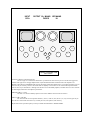
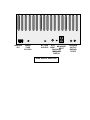
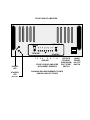
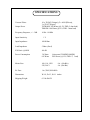
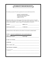
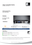
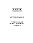
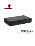
MANLEY
LABORATORIES, INC.
OWNER'SMANUAL
MANLEY 250 / 100 WATT
MONOBLOCK AMPLIFIER
MANLEY LABORATORIES, INC.
13880 MAGNOLIA AVE.
CHINO, CA. 91710
TEL: (909) 627-4256
FAX: (909) 628-2482
CONTENTS
SECTION
PAGE
INTRODUCTION
3
MAINS CONNECTIONS
4
CONNECTING YOUR AMPLIFIER
5
DIAGRAM 2
6
TOP PANEL
BIAS PROCEDURES
7
OPERATIONAL NOTES
8
SPECIFICATIONS
9
WARRANTY
10
WARRANTY REGISTRATION
11
INTRODUCTION
THANK YOU!...
for choosing the Manley 250/100 Monoblock Amplifiers. Designed by David Manley, the Manley 250/100
Monoblock Amplifiers use only the best available components, with the shortest and cleanest signal path possible,
and with the use of our own in-house CNC machine shop we can provide you with a amplifier that looks as good
as it sounds.
The circuit and the components used have been chosen carefully after years of development and refinement for
reliability, constancy and most importanly, musical, accurate, and emotional delivery of the sound. The circuit
topology is similar to other designs in the MANLEY range. This amplifier is configured to switch between triode
or tetrode operation which allows the user to choose between the sonic benefits and seductive qualities of triode
and the more powerful tetrode operation mode. We emphasize big, beefy reservoir capacitors in the high voltage
supplies giving plenty of instant energy for dynamic performance of transient peaks and bass performance which
often exceeds that of rival solid-state amplifiers. We run high voltages on the plates of the output tubes and are
thus able to run them at lower current which will result in longer life for the output tubes, and careful use of the
'EVER-WARM' power switching should also greatly increase the life of the output tubes as well as allowing your
amplifiers to always be ready for pleasurable listening. Each output tube has its own bias adjust, and the
procedure for adjusting each tube's current draw is described in this manual. The output transformer is a
revolutionary new design by David Manley which is wound on the Manley Labs factory premesis. Its stellar
performance will be obvious upon first listening. The secret is in keeping both phases of the push-pull halves
always equal, and in this new output transformer design, David has achieved just that. The output transformer has
been factory set for an optimum 5 ohm load which will drive most speakers.
Thank you again, and please enjoy!
GENERAL NOTES
LOCATION & VENTILATION
The Manley 250/100 Monoblock Amplifiers must be installed in a stable location with ample ventilation. Allow
a minimum of 2 inches of clearance on the top and sides of the amplifiers, such that a constant flow of air can
flow. Do not place amplifiers directly on high pile carpet or any other surface that will block the ventilation
vents underneath the amplifiers. If you have small children or pets, you should consider placing the amplifiers out
of reach to prevent damage to the amplifier or damage to your small children or pets by the amplifier as the tubes
do get hot during operation.
WATER & MOISTURE
As with any electrical equipment, these amplifiers should not be used near water or moisture. If liquid enters the
amplifier, it must be immediately returned to your dealer for servicing.
SERVICING
The user should not attempt to service the amplifier beyond that described in the owner's manual. Refer all
servicing other than biasing and tube replacement to Manley Laboratories
SPECIAL NOTES
Tubes may become loose during transit. Straighten and press down each tube before plugging the amplifier into
the mains socket. Furthermore, do not touch the tubes after the amplifier has been switched on, as the tubes
become very hot during operation and should only be handled after the power has been turned off and the tubes
have cooled.
WARNING!
!
TO PREVENT THE RISK OF ELECTRIC SHOCK
DO NOT OPEN THE CABINET
REFER SERVICING TO
QUALIFIED PERSONEL
MAINS CONNECTIONS
Your amplifier has been factory set to the correct mains voltage for your country. The voltage
setting is marked on the serial badge, located on the rear panel. Check that this complies with
your local supply.
Export units for certain markets have a moulded mains plug fitted to comply with local
requirements. If your unit does not have a plug fitted the coloured wires should be connected
to the appropriate plug terminals in accordance with the following code.
GREEN/YELLOW
BLUE
BROWN
EARTH
NEUTRAL
LIVE
terminal
terminal
terminal
As the colours of the wires in the mains lead may not correspond with the coloured marking
identifying the terminals in your plug proceed as follows;
The wire which is coloured GREEN/YELLOW must be connected to the terminal in the plug
which is marked by the letter E or by the safety earth symbol or coloured GREEN or GREEN
and YELLOW.
The wire which is coloured BLUE must be connected to the terminal in the plug which is
marked by the letter N or coloured BLACK.
The wire which is coloured BROWN must be connected to the terminal in the plug which is
marked by the letter L or coloured RED.
DO NOT CONNECT/SWITCH ON THE MAINS SUPPLY UNTIL ALL OTHER
CONNECTIONS HAVE BEEN MADE.
CONNECTING YOUR AMPLIFIER
Setting up your amplifiers is rather easy.
1. Connect all source components (turntable, CD, Tuner, Tape DAT, etc.) to
your preamplifier.
2. Connect the interconnects from the output of the preamplifier or switching
center to the RCA input on the top rear of the amplifiers. IF your source has
a truly BALANCED output, connect TO the XLR input and select the
balanced input. This switch is a locking type to prevent inadvertant or accidental switching (say, while cleaning). To engage this switch, PULL OUT
the toggle then gently switch the toggle. Do not force the switch to engage or
you may break it. If using a standard UNBALANCED source, select and use
the unbalanced RCA connector. This amplifier will not function properly if
you are using the wrong input for your application. The XLR input is wired
PIN1 GROUND, PIN 2 POSITIVE, PIN 3 NEGATIVE PHASE.
3. Connect the hot or "+" speaker cable to the red binding post and the common
or "-" speaker cable to the black binding post (See diagarm 2). Ensure that
the other end of the cable is connected correctly to the speaker. Tighten the
binding posts by hand. If you use a nut-driver (3/8") do not over-tighten the
posts or you may break the connections inside the amplifier.
4. Ensure that the "mains" switch on the front panel is in the "off" or "0" position and the OPERATE / STANDBY switch is in the STANDBY mode.
5. Turn on Preamplifier and any source components you plan to use.
6. Plug amplifier into wall outlet.
7. Switch the square mains power switch to the ON position and allow the
amplifier a minute or so to 'warm up'. The blinking LED will indicate that
the amplifier is in STANDBY mode.
8. Engage the soft-start swich to the OPERATE position. The blinking standby
LED will extinguish.
9. Turn up the volume and enjoy.
10. After your listening session, if you wish to leave the amplifier in the energysaving and 'EVER-WARM' STANDBY mode, engage the OPERATE/
STANDBY switch to the STANDBY position. The standby blinking LED
will remind you that the amplifier is in STANDBY mode.
OUTPUT B+ MAINS IEC MAINS
FUSES
IN
INPUT
RCA
3
1
2
4
6414
6414
10
8
6
5
7
9
12AT7
Amplifier Overhead View
Tube Location
OUTPUT TUBES:10 x RUSSIAN EL34G
The EL34 type we recommend are the Russian up-rated EL34G. This has been proven to be the most rugged and
reliable of this type and we strongly emphasize that only the RUSSIAN EL34G's should be used in this amplifier. The
MANLEY 250/100 WATT MONOBLOCK has been thoroughly optimised around this tube. Use of unapproved tube types can
and will void your warranty. We have selected the tubes for equality of current draw in our custom-built computerized tube
tester for each of your monoblocks . Although each tube bias can be individually adjusted, "batched" tubes as we have selected
are thouroughly beneficial to the amplifier's performance.
DRIVER TUBES: 1 x 6414
The 6414 is an American military uprated version of the 12BH7A with increased current drive.
INPUT TUBE: 12AT7WA
The 12AT7WA has several equivalent numbers, (12AT7, 12AT7A, 6201, ECC81, etc.) Any of these types may be
used. We have selected this 12AT7WA very carefully for noise, microphonics, and constancy.
Replacement tubes of premium quality are always available from MANLEY LABORATORIES.
MAINS IN
IEC
MAINS
FUSE
SLO-BLO
B+ FUSE
SLO-BLO
XLR
BALANCED
INPUT
BALANCED
UNBALANCED
SWITCH
RCA
INPUT
REAR VIEW OF AMPLIFIER
SPEAKER
OUTPUT
BINDING
POSTS
FRONT VIEW OF AMPLIFIER
TRIODE
OPERATE
TETRODE
STANDBY
1 2
POWER
LED
STANDBY
LED
(BLINKING)
3 4
5 6
GROUND
7
8
FRONT VIEW OF AMPLIFIER
WITH INSERT REMOVED
OPERATE
STANDBY
EVER-WARM
SOFT START
SWITCH
SHOWING BIAS MEASUREMENT POINTS
AND BIAS ADJUST POINTS
MAINS
POWER
ON / OFF
SWITCH
BIAS PROCEDURES
The Manley 250/100 Monoblock Amplifiers uses a fixed bias system that requires very little
attention. If you wish to adjust or check the bias, follow the following steps.
For this procedure you will need a voltmeter (a hand held autoranging DMM digital
multimeter is the easiest), a 3/32" allen key, and a small 1/8" flat screwdriver.
1.
Remove the four silver hex cap head screws which secure the insert to the faceplate.
Also then remove by hand, the two knurled black decorative nuts on the Triode and SoftStart switches. On page 8, which shows the FRONT panel of the amplifier, you can see 8 red
tip jacks plus the ground point. To measure the current draw of each output tube place the
POSITIVE meter probe into the first red tip jack. (If you read a negative reading reverse the
meter probes, no harm will be done.)
Set the meter to read 'millivolts' DC (direct current).
2.
Each of the ten output tubes can have its own bias adjusted by adjusting its own bias
adjust pot. Above the measurement tip jacks you can see each tube's bias adjust pot.
3.
The first step to setting the bias is to turn on the amplifier and ensure that there is
zero signal input, either leave the preamplifier or source signal turned off or unplug the
amplifier input. Also, leave your loudspeakers connected as these provide an ideal load on
the output. (DO NOT EVER OPERATE YOUR AMPLIFIER WITHOUT SPEAKERS
CONNECTED!) It is recommended that you leave the amplifier on long enough to ensure
that the tubes have reached their stable current draw, at least 1/2 hour is recommended.
5.
Place the meter probes in the first red tip jack . Adjust the first bias trim pot slowly
until you measure 275mV to 300 mVDC (0.275V to 0.300VDC). Since you are measuring
across a 10 ohm cathode resistor, this would correspond to a 27 to 30 mA current draw for
each tube by Ohm's law. A reading of 0mV can indicate a failed tube, or an open cathode
resistor. A reading of 0mV on ALL tubes (powered on condition) can mean the B+ fuse has
blown. The cause of this should be investigated before simply putting a new fuse in.
6.
If you are unable to bring the bias voltage down to 300 mV on any tube then we
recommend that the tube be carefully watched or replaced.
7.
Follow step five with the remaining tubes, switching to the next tube point and
adjusting the next trim pot each time. After you have adjusted all the output tubes, recheck
and repeat the procedure as they will drift a little bit during adjustment. Once they are all set,
your amplifier should be in perfect operation.
OPERATIONAL NOTES
SWITCHING ON -- SOFT START
The MANLEY 250/100 is equipped with a SOFT-START circuit which lessens the initial stress the
amplifier takes upon turn-on. We recommend that you use this soft start facility whenever you turn
the amplifier on and especially when cold.
1. Ensure that the "mains" switch on the front panel is in the "off" or "0" position
and the OPERATE / STANDBY switch is in the STANDBY mode.
2. Turn on preamplifiers and all source components you plan to use and let them warm up
for a minute.
3. Switch the square mains power switch to the ON position and allow the amplifier a
minute or so to 'warm up'. The blinking LED will indicate that the amplifier is in
STANDBY mode.
4. Engage the soft-start swich to the OPERATE position. The blinking standby LED will
extinguish.
5. Turn up the volume and enjoy.
THE EVER-WARM MODE
After your listening session, if you wish to leave the amplifier in the energy-saving and 'EVERWARM' STANDBY mode, engage the OPERATE/STANDBY switch to the STANDBY position.
The standby blinking LED will remind you that the amplifier is in STANDBY mode. The amplifier
will draw only 400mA (30 watts @120VAC) from the mains outlet-- certainly an energy saving
way to keep your amplifiers always ready to listen to!
TRIODE / TETRODE OPERATION:
With the TRIODE / TETRODE switch, the amplifier may be set for TRIODE or
TETRODE operation. When the switch is in the lower position, the amplifier is in TETRODE
mode which will produce well over 250 watts. When the switch is in the upper position, the
amplifier is in TRIODE mode which will produce half the power of TETRODE operation but as
fans of triodes know, nothing can match that sweet seductive sound of triodes! For some more
demanding energetic music, large rooms, or for power hungry inefficient loadspeakers, you might
find you will need the extra power of tetrode operation. Other times and other situations will find
you very well satisfied with the triode mode. One major rule applies for switching between triode
and tetrode:
THE AMPLIFIER MUST BE TURNED OFF BEFORE SWITCHING BETWEEN
TRIODE AND TETRODE!!!!
Follow turn on SOFT START procedure above when re-powering up the unit.
TUBE LIFE
You should expect extended life from the tubes in your MANLEY 250/100 if you adhere to the
procedures described above and check your bias at least once every 2-3 months. We stock all the
tubes in these amplifiers should you ever need replacements (and at very reasonable prices too!)
FUSES
The fuses used in your amplifier are standard 1/4" x 1 1/4" SLO-BLO types. The correctly rated
fuse has been installed at the factory for your country's voltage. If replacing a fuse, always unplug
the amplifier's power cord from the wall outlet and always use the exact same type and ampere
rating fuse as the one you are replacing. Failure to do so will void your warranty and can be a
dangerous fire hazard. NEVER replace a fuse with thick wire, tin foil, gum wrappers, or anything
else other than the correct fuse!
SPECIFICATIONS
Vacuum Tubes:
Output Power
Frequency Response, +/- .5 dB
Input Sensitivity
10 x EL34G (Output), 2 x 6414 (Driver),
1 x 12AT7 (Input)
TETRODE: 240 Watts (@1.5% THD 5 ohm load)
TRIODE: 100 Watts (@1.5% THD 5 ohm load)
10 Hz - 80 KHz
1V
Input Impedance
100 KOhm
Load Impedance
5 Ohm (fixed)
S/N Ratio @440W
-80 dB
Power Consumption
30 Watts
815 Watts
Mains Fuse
100, 110, 120V
220, 240 V
B+ Fuse
1 A (250V)SLO-BLO
Dimensions
W=19, D=13, H=11 inches
Shipping Weight
63 lbs EACH
Quiescent (STANDBY MODE)
Full Power (@1.5% THD 5Ω load)
8 A (Slo-Blo)
4 A (Slo-Blo)
WARRANTY
All Manley Laboratories equipment is covered by a limited warranty against defects in materials
and workmanship for a period of 90 days from date of purchase to the original purchaser only. A
further optional limited 5 year warranty is available to the original purchaser upon proper
registration of ownership within 30 days of date of first purchase.
Proper registration is made by filling out and returning to the factory the warranty card attached to
this general warranty statement, along with a copy of the original sales receipt as proof of the
original date of purchase. Only 1 card is issued with each unit, and the serial number is already
recorded on it.
If the warranty registration card has already been removed then this is not a new unit, and is
therefore not warranted by the factory. If you believe this to be a new unit then please contact the
factory with the details of purchase.
This warranty is provided by the dealer where the unit was purchased, and by Manley Laboratories,
Inc. Under the terms of the warranty defective parts will be repaired or replaced without charge,
excepting the cost of tubes. No warranty is offered on tubes, unless:
1. a Manley Laboratories preamplifier is used with a Manley Laboratories amplifier, and
2. the warranty registration card is filled out.
In such a case a 6 month warranty on tubes is available with the correct recording of the serial
number of the preamplifier on your warranty registration card.
If a Manley Laboratories product fails to meet the above warranty, then the purchaser's sole
remedy shall be to return the product to Manley Laboratories, where the defect will be repaired
without charge for parts and labour. The product will then be returned via prepaid, insured freight,
method and carrier to be determined solely by Manley Laboratories. All returns to the factory must
be in the original packing, (new packing will be supplied for no charge if needed), accompanied by
a written description of the defect, and must be shipped to Manley Laboratories via insured freight
at the customer's own expense. Charges for unauthorized service and transportation costs are not
reimbursable under this warranty, and all warrantees, express or implied, become null and void
where the product has been damaged by misuse, accident, neglect, modification, tampering or
unauthorized alteration by anyone other than Manley Laboratories.
The warrantor assumes no liability for property damage or any other incidental or consequental
damage whatsoever which may result from failure of this product. Any and all warrantees of
merchantability and fitness implied by law are limited to the duration of the expressed warranty.
All warrantees apply only to Manley Laboratories products purchased and used in the USA.
Some states do not allow limitations on how long an implied warranty lasts, so the above
limitations may not apply to you. Some states do not allow the exclusion or limitation of incidental
or consequential damges, so the above exclusion may not apply to you.
This warranty gives you specific legal rights and you may also have other rights which vary from
state to state.
WARRANTY REGISTRATION
We ask that you please fill out this registration form and send the bottom half to:
MANLEY LABORATORIES
REGISTRATION DEPARTMENT
13880 MAGNOLIA AVE.
CHINO CA, 91710
Registration entitles you to product support, full warranty benefits, and notice of product
enhancements and upgrades. You MUST complete and return the following to validate your
warranty and registration. Thank you again for choosing Manley Laboratories.
MODEL ____________________
SERIAL No. ______________________
PURCHASE DATE ______________ SUPPLIER ______________________
--------------------------------------------------------------------------------------------------PLEASE DETACH THIS PORTION AND SEND IT TO MANLEY LABORATORIES
MODEL: MANLEY REFERENCE 250/100 MONOBLOCK
SERIAL No. ______________________________
PURCHASE DATE ______________ SUPPLIER _______________________
NAME OF OWNER _______________________________________________
ADDRESS ______________________________________________________
CITY, STATE, ZIP ________________________________________________
TELEPHONE NUMBER ___________________________________________
Comments???? ___________________________________________________
________________________________________________________________