1
5011613009
2011-04- 18
FE0 9
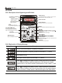
VFD-F Series
Preface
Thank you for choosing DELTA’s high-performance VFD-F Series. VFD-F Series are
manufactured by adopting high-quality components, material and incorporating the latest
microprocessor technology available.
Getting Started
This manual will be helpful in the installation, parameter setting, troubleshooting, and daily
maintenance of the AC motor drives. To guarantee safe operation of the equipment, read
the following safety guidelines before connecting power to the AC drives. Keep this
operating manual handy and distribute to all users for reference.
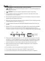
!
!
!
WARNING
Always read this manual thoroughly before using VFD-F series AC Motor Drives.
Ensure that VFD-F is grounded in a correct way before putting it into use.
!
DANGER! AC input power must be disconnected before any maintenance. Do not connect
or disconnect wires and connectors while power is applied to the circuit. Maintenance must
be performed by qualified technicians.
!
CAUTION! There are highly sensitive MOS components on the printed circuit boards.
These components are especially sensitive to static electricity. To avoid damage to these
components, do not touch these components or the circuit boards with metal objects or
your bare hands.
!
DANGER! A charge may still remain in the DC-link capacitor with hazardous voltages even
if the power has been turned off. To avoid personal injury, do not remove the cover of the
AC drive until all “DISPLAY LED” lights on the digital keypad are off. Please note that there
are live components exposed within the AC drive. Do not touch these live parts.
!
CAUTION! Ground the VFD-F using the ground terminal. The grounding method must
comply with the laws of the country where the AC drive is to be installed. Refer to Basic
Wiring Diagram.
!
DANGER! The AC drive may be destroyed beyond repair if incorrect cables are connected
to the input/output terminals. Never connect the AC drive output terminals U/T1, V/T2, and
W/T3 directly to the AC main circuit power supply.
!
CAUTION! The final enclosures of the AC drive must comply with EN50178. (Live parts
shall be arranged in enclosures or located behind barriers that meet at least the
requirements of the Protective Type IP20. The top surface of the enclosures or barrier that
is easily accessible shall meet at least the requirements of the Protective Type IP40).
(VFD-F series corresponds with this regulation.)
!
CAUTION! The rated voltage for the AC motor drive must be ≤ 240V for 230V models (≤
480V for 460V models) and the mains supply current capacity must be ≤ 5000A RMS
(≤10000A RMS for the ≥ 40hp (30kW) models)
CAUTION! Heat sink may heat up over 70oC (158oF), during the operation. Do not touch
the heat sink.
DELTA ELECTRONICS, INC. ALL RIGHTS RESERVED
VFD-F Series
TABLE OF CONTENTS
CHAPTER 1
RECEIVING AND INSPECTIONS
1.1 Nameplate Information ........................................................................ 1 - 1
1.2 Model Explanation ............................................................................... 1 - 1
1.3 Serial Number Explanation.................................................................. 1 - 2
CHAPTER 2
STORAGE AND INSTALLATION
2.1 Storage................................................................................................. 2 - 1
2.2 Installation............................................................................................ 2 - 2
CHAPTER 3
WIRING
3.1 Basic Wiring Diagram .......................................................................... 3 - 2
3.2 External Wiring .................................................................................... 3 - 5
3.3 Main Circuit Connection ...................................................................... 3 - 6
3.4 Control Terminals................................................................................. 3 - 9
3.5 Specifications for Power Terminals and Control Terminals ................. 3 - 11
3.6 Wiring Notes ........................................................................................ 3-14
3.7 Motor Operation Precautions .............................................................. 3-16
CHAPTER 4
DIGITAL KEYPAD OPERATION
4.1 VFD-PU01 ........................................................................................... 4 - 2
4.1.1 Description of the Digital Keypad VFD-PU01 ............................... 4 - 2
4.1.2 Explanation of Display Message................................................... 4 - 2
4.1.3 Operation Steps of the Digital Keypad VFD-PU01 ....................... 4 - 4
DELTA ELECTRONICS, INC. ALL RIGHTS RESERVED
VFD-F Series
4.2 KPF-CC01 ........................................................................................... 4 - 5
4.2.1 Description of the Digital Keypad KPF-CC01 ............................... 4 - 5
4.2.2 Explanation of Display Message................................................... 4 - 5
4.2.3 KPF-CC01 Operation Flow Chart ................................................. 4 - 6
CHAPTER 5
DESCRIPTION OF PARAMETER SETTINGS
5.1 Group 0: AC Drive Status Parameters................................................. 5 - 1
5.2 Group 1: Basic Parameters ................................................................. 5 - 4
5.3 Group 2: Operation Method Parameters ............................................. 5 - 9
5.4 Group 3: Output Function Parameters ................................................ 5-15
5.5 Group 4: Input Function Parameters ................................................... 5-19
5.6 Group 5: Multi-step Speed Frequency Parameters............................. 5-24
5.7 Group 6: Protection Parameters.......................................................... 5-30
5.8 Group 7: AC Drive and Motor Parameters .......................................... 5-36
5.9 Group 8: Special Parameters .............................................................. 5-39
5.10 Group 9: Communication Parameters............................................... 5-45
5.11 Group 10: PID Control Parameters ................................................... 5-60
5.12 Group 11: Fan and Pump Control Parameters.................................. 5-63
CHAPTER 6
MAINTENANCE AND INSPECTIONS
6.1 Periodic Inspection .............................................................................. 6 - 1
6.2 Periodic Maintenance .......................................................................... 6 - 1
CHAPTER 7
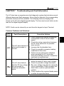
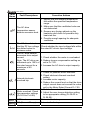
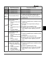
TROUBLESHOOTING AND FAULT INFORMATION........... 7 - 1
DELTA ELECTRONICS, INC. ALL RIGHTS RESERVED
VFD-F Series
CHAPTER 8
SUMMARY OF PARAMETER SETTINGS ............................ 8 - 1
APPENDIX A SPECIFICATIONS ................................................................ A - 1
APPENDIX B
ACCESSORIES
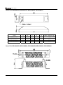
B.1 All Brake Resistors & Brake Units Used in AC Motor Drives .............. B - 1
B.1.1 Dimensions and Weights for Brake Resistors.............................. B - 3
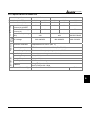
B.1.2 Specifications for Brake Unit ........................................................ B - 5
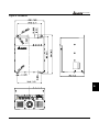
B.1.3 Dimensions for Brake Unit............................................................ B - 6
B.2 AMD-EMI Filter Cross Reference........................................................ B - 8
B.3 AC Reactor .......................................................................................... B-10
B.3.1 AC Input Reactor Recommended Value ...................................... B-10
B.3.2 AC Output Reactor Recommended Value.................................... B-11
B.4 Non-fuse Circuit Breaker Chart........................................................... B-12
B.5 Fuse Specification Chart ..................................................................... B-13
B.6 PU06.................................................................................................... B-14
B.6.1 Description of the Digital Keypad VFD-PU06............................... B-14
B.6.2 Explanation of Display Message .................................................. B-14
B.6.3 PU06 Operation Flow Chart ......................................................... B-15
B.7 Relay Card .......................................................................................... B-16
B.8 Zero Phase Reactor ............................................................................ B-18
APPENDIX C
DIMENSIONS........................................................................ C - 1
DELTA ELECTRONICS, INC. ALL RIGHTS RESERVED
VFD-F Series
CHAPTER 1 RECEIVING AND INSPECTION
1
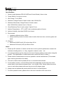
This VFD-F AC drive has gone through rigorous quality control tests at the factory before
shipment. After receiving the AC drive, please check for the following:
Receiving
9 Check to make sure that the package includes an AC drive, the User Manual, dust
covers and rubber bushings.
9 Inspect the unit to insure it was not damaged during shipment.
9 Make sure that the part number indicated on the nameplate corresponds with the part
number of your order.
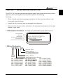
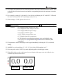
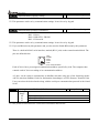
1.1 Nameplate Information: Example for 7.5HP/5.5kW 3-phase 460V AC drive
AC Drive Model
Input Spec.
Output Spec.
Output Frequency Range
Enclosure type
Serial Number & Bar Code
MODEL : VFD055F43A
INPUT
: 3PH 380-480V 50/60Hz 14A
OUTPUT : 3PH 0-480V 13A 9 .9KVA 7.5HP
Frequency Range : 1.5-120Hz
Enclosure: TYPE 1
055F43AT201001
DELTA ELECTRONICS INC.
MADE IN XXXXX
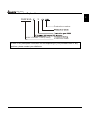
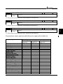
1.2 Model Explanation
VFD 055 F
43 A
Version Type
Input Voltage
23:Three phase 230V
43:Three phase 460V
Series
Name
007: 1.0HP(0.75kW)
015: 2.0HP(1.5kW)
022: 3.0HP(2.2kW)
037: 5.0HP(3.7kW)
055: 7.5HP(5.5kW)
075: 10 HP(7.5kW)
110: 15 HP(11kW)
VFD-F Series
Applicable motor capacity
150: 20HP(15kW)
750: 100HP(75kW)
900: 120HP(90kW)
220: 30 HP(22kW)
1100: 150HP(110kW)
300: 40HP(30kW)
1320: 175HP(130kW)
370: 50HP(37kW)
1600: 215HP(160kW)
450: 60HP(45kW)
1850: 250HP(185kW)
550: 75HP(55kW)
2200: 300HP(220kW)
DELTA ELECTRONICS, INC. ALL RIGHTS RESERVED
1-1
VFD-F Series
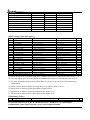
1.3 Series Number Explanation
055F43A
1
3
Production number
460V 3-PHASE 7.5HP(5.5kW)
Production model
If there is any nameplate information not corresponding to your purchase order or any
problem, please contact your distributor.
1-2
DELTA ELECTRONICS, INC. ALL RIGHTS RESERVED
VFD-F Series
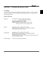
CHAPTER 2 STORAGE AND INSTALLATION
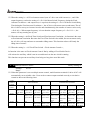
2.1 Storage
The AC drive should be kept in the shipping carton before installation. In order to retain the
warranty coverage, the AC drive should be stored properly when it is not to be used for an
extended period of time.
Ambient Conditions:
Operation
Air Temperature: -10oC to +40oC (14oF to 104oF)
+50oC (122oF) without dust cover.
Atmosphere pressure: 86 to 106 kPa
Installation Site Altitude: below 1000m
Vibration: Maximum 9.80 m/s2 (1G) at less than 20Hz
Maximum 5.88 m/s2 (0.6G) at 20Hz to 50Hz
Storage
Temperature: -20oC to +60oC (-4oF to 140oF)
Relative Humidity: Less than 90%, no condensation allowed
Atmosphere pressure: 86 to 106 kPa
Transportation
Pollution Degree
Temperature: -20oC to +60oC (-4oF to 140oF)
Relative Humidity: Less than 90%, no condensation allowed
Atmosphere pressure: 86 to 106 kPa
Vibration: Maximum 9.86 m/s2 (1G) at less than 20Hz, Maximum 5.88
m/s2 (0.6G) at 20Hz to 50Hz
2: good for a factory type environment.
DELTA ELECTRONICS, INC. ALL RIGHTS RESERVED
2-1
2
VFD-F Series
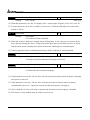
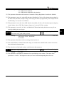
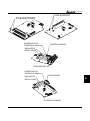
2.2 Installation
CAUTION
The control, power supply and motor leads must be laid separately. They must not be
fed through the same cable conduit / trunking.
High voltage insulation test equipment must not be used on cables connected to the
drive.
Improper installation of the AC drive will greatly reduce its life. Be sure to observe the
following precautions when selecting a mounting location.
Failure to observe these precautions may void the warranty!
Do not mount the AC drive near heat-radiating elements or in direct sunlight.
Do not install the AC drive in a place subjected to high temperature, high humidity,
excessive vibration, corrosive gases or liquids, or airborne dust or metallic particles.
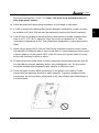
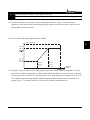
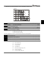
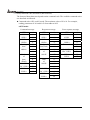
Mount the AC drive vertically and do not restrict the air flow to the heat sink fins.
The AC drive generates heat. Allow sufficient space around the unit for heat dissipation.
150mm
50mm
VFD-F
F
H
U
VFD-PU 01
RUN STOP JO G FWD REV
JOG
RUN
STOP
RESET
50mm
Air Flow
150mm
2-2
DELTA ELECTRONICS, INC. ALL RIGHTS RESERVED
VFD-F Series
CHAPTER 3 WIRING
DANGER
Hazardous Voltage
Before accessing the AC drive:
Disconnect all power to the AC drive.
Wait five minutes for DC bus capacitors discharge.
Any electrical or mechanical modification to this equipment without prior written
consent of Delta Electronics, Inc. will void all warranties and may result in a safety
hazard in addition to voiding the UL listing.
Short Circuit Withstand:
The rated voltage for the AC motor drive must be ≤ 240V for 230V models (≤
480V for 460V models) and the mains supply current capacity must be ≤
5000A RMS (≤10000A RMS for the ≥ 40hp (30kW) models)
DELTA ELECTRONICS, INC. ALL RIGHTS RESERVED
3-1
3
VFD-F Series
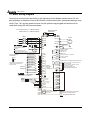
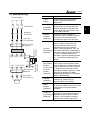
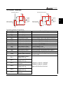
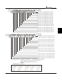
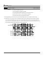
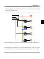
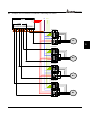
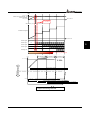
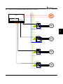
3.1 Basic Wiring Diagram
Users must connect wires according to the following circuit diagram shown below. Do not
plug a Modem or telephone line to the RS-485 communication port, permanent damage may
result. Pins 1 & 2 are the power sources for the optional copy keypad and should not be
used while using RS-485 communication.
For 230V series, 1~15HP models
460V series, 1~20HP models
NFB
+1 +2/B1
R(L1)
S(L2)
T(L3)
R
S
T
NFB
Source
Sw1
Sink
Please refer to the following
wiring for Sink mode and
Source mode.
Factory
Setting
24V
FWD
REV
EF
MI1
MI2
MI3
MI4
MI5
MI6
MI7
MI8
DCM
1/2 Accel/Decel Switch
Digital Signal Common
Don't apply the mains voltage
directly to above terminals.
SW2
0-5V
RA1 Multi-function indication
output contacts
RB1 240VAC 2.5A
120VAC 5A
RC1 28VDC
5A
RA2
RB2
RC2
AFM1
Multifunction
Input
Terminals
E
5k
3
2
1
Power Supply
+10V 20mA
AVI
4~20mA
4~20mA
1:+EV
2:GND
3:SG4:SG+
5:NC
6:NC
AFM2
ACM
Master Frequency
0~10V (47k )
ACI1
ACI2
ACM
Analog Signal Common
*RS-485
Factory setting: no function
Factory setting:
no function
Multi-function analog output terminals
Factory setting: output frequency
0~10Vdc/2mA
Factory setting: output current
0~20mA/4~20mA
Max. Impedance: 500Ω
Analog Signal Common
E
RY00
+10V
0-10V
M
3~
V(T2)
RC
FWD/STOP
REV/STOP
E.F.
Multi-step 1
Multi-step 2
Multi-step 3
Multi-step 4
RESET
JOG
Motor
E
RB
Accel/Decel Prohibit
NO TE
B2 U(T1)
W(T3)
E
SA
Recommended circuit
MC
when power supply is
turned OFF by a fault
output.
ON
OFF
If the fault occurs, the
contact will be ON to turn
MC
off the power and protect the power system.
Factory Setting:
Sink Mode
Brake Resistor
(Optional)
RA3 Optional
RC3
RA4
RC4
RA5
RC5
RA6
RC6
RA7
RC7
RA8
RC8
Relay B.D.
Serial Communication
Interface
Main circuit (power) terminals
Control circuit terminals
Shielded leads&cable
3-2
DELTA ELECTRONICS, INC. ALL RIGHTS RESERVED
VFD-F Series
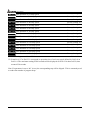
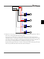
Brake Unit (Optional)
For 230V series, 20HP and above models
460V series, 25HP and above models
NFB
NFB
Recommended circuit
MC
when power supply
is turned OFF by a
fault output.
ON
If the fault occurs, the
OFF
contact will be ON to turn
off the power and protect the power system. MC
Sw1
Sink
Please refer to the following
wiring for Sink mode and
Source mode.
Factory
Setting
FWD/STOP
REV/STOP
E.F.
Multi-step 1
Multi-step 2
Multi-step 3
Multi-step 4
RESET
JOG
1/2 Accel/Decel Switch
Digital Signal Common
24V
FWD
REV
EF
MI1
MI2
MI3
MI4
MI5
MI6
MI7
MI8
DCM
RA2
RB2
RC2
AFM1
Multifunction
Input
Terminals
5k
AVI
4~20mA
1:+EV
2:GND
3:SG4:SG+
5:NC
6:NC
DELTA ELECTRONICS, INC. ALL RIGHTS RESERVED
ACM
RY00
Power Supply
+10V 20mA
4~20mA
AFM2
Multi-function indication
output contacts
240VAC 2.5A
120VAC 5A
28VDC 5A
Factory setting: no function
Factory setting:
no function
Multi-function Analog Output Terminals
Factory setting: output frequency
0~10Vdc/2mA
Factory setting: output current
0~20mA/4~20mA
Max. Impedance: 500Ω
Analog Signal Common
E
E
3
2
1
M
3~
RA1
RB1
RC1
+10V
0-10V
Motor
V(T2)
RC
Don't apply the mains voltage
directly to above terminals.
SW2
0-5V
U(T1)
E
RB
Accel/Decel Prohibit
NO TE
Brake Resistor
(Optional)
W(T3)
E
SA
Factory setting: Sink Mode
Source
B1
P N B2
+1
+2
R(L1)
S(L2)
T(L3)
R
S
T
VFDB
Master Frequency
0~10V (47k )
ACI1
ACI2
ACM
Analog Signal Common
*RS-485
RA3 Optional
RC3
RA4
RC4
RA5
RC5
RA6
RC6
RA7
RC7
RA8
RC8
Relay B.D.
Serial Communication
Interface
Main circuit (power) terminals
Control circuit terminals
Shielded leads&cable
3-3
3
VFD-F Series
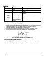
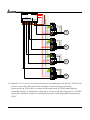
Wiring for SINK mode and SOURCE mode
JOG
1/2 Accel/Decel switch
MI7
MI8
Sink
Sw1
Source
JOG
1/2 Accel/Decel switch
3-4
MI7
MI8
DELTA ELECTRONICS, INC. ALL RIGHTS RESERVED
VFD-F Series
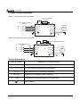
3.2 External Wiring
Items
Power Supply
Power
supply
FUSE/NFB
Fuse/NFB
(Optional)
Magnetic
Contactor
Input AC
Line Reactor
EMI Filter
R/L1 S/L2 T/L3 E
+/B1
B2
-
U/T1 V/T2 W/T3
E
BR
VFDB
Brake Unit
Brake Resistor BR (Optional)
(Optional)
Zero-phase
Reactor
Zero-phase
Reactor
Output AC
Line Reactor
Motor
Magnetic
contactor
(Optional)
Explanations
Please follow the specific power
supply requirements shown in
Appendix A.
There may be an inrush current
during power up. Please check the
chart of Appendix B and select the
correct fuse with rated current. Use
of an NFB is optional.
Please do not use a Magnetic
contactor as the I/O switch of the AC
motor drive, as it will reduce the
operating life cycle of the AC drive.
Used to improve the input power
factor, to reduce harmonics and
provide protection from AC line
disturbances (surges, switching
Input AC
spikes, short interruptions, etc.). AC
Line Reactor line reactor should be installed when
the power supply capacity is 500kVA
(Optional)
or more or advanced capacity is
activated. The wiring distance should
be ≤ 10m. Refer to appendix B for
details.
Zero-phase reactors are used to
reduce radio noise especially when
audio equipment is installed near the
inverter. Effective for noise reduction
(Ferrite Core
on both the input and output sides.
Common
Attenuation quality is good for a wide
Choke)
range from AM band to 10MHz.
(Optional)
Appendix B specifies the zero-phase
reactor. (RF220X00A)
Zero-phase
Reactor
EMI filter
(Optional)
Brake
Resistor
(Optional)
To reduce electromagnetic
interference, please refer to
Appendix B for more details.
Used to reduce the deceleration time
of the motor. Please refer to the chart
in Appendix B for specific Brake
Resistors.
Motor surge voltage amplitude
Output AC
depends on motor cable length. For
Line Reactor applications with long motor cable
(>20m), it is necessary to install a
(Optional)
reactor at the inverter output side.
DELTA ELECTRONICS, INC. ALL RIGHTS RESERVED
3-5
3
VFD-F Series
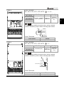
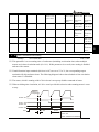
3.3 Main Circuit Connection
Figure 1 for the main circuit terminals
Brake Resistor
(Optional)
Non-fuse breaker
(NFB)
R
S
T
-
B2
+1 +2/B1
MC
R(L1)
S(L2)
T(L3)
E
U(T1)
V(T2)
W(T3)
Motor
IM
3~
E
Figure 2 for the main circuit terminals
VFDB
Non-fuse breaker
(NFB)
MC
R
S
T
+2
+1
R(L1)
S(L2)
T(L3)
Brake Resistor (Optional)
-
U(T1)
V(T2)
W(T3)
E
Motor
IM
3~
E
Terminal Explanations
Terminal Symbol
Explanation of Terminal Function
R/L1, S/L2, T/L3
AC line input terminals
U/T1, V/T2, W/T3
AC drive output terminals motor connections
+1,+2
Connections for DC Link Reactor (optional)
+2/B1~B2
+2~ -,+2/B1~ -
Connections for Brake Resistor (optional)
Connections for External Brake Unit (VFDB series)
Earth Ground
3-6
DELTA ELECTRONICS, INC. ALL RIGHTS RESERVED
VFD-F Series
Mains power terminals (R/L1, S/L2, T/L3)
Connect these terminals (R/L1, S/L2, T/L3) via a non-fuse breaker or earth leakage
breaker to 3-phase AC power (some models to 1-phase AC power) for circuit protection.
It is unnecessary to consider phase-sequence.
It is recommended to add a magnetic contactor (MC) in the power input wiring to cut off
power quickly and reduce malfunction when activating the protection function of AC
motor drives. Both ends of the MC should have an R-C surge absorber.
Please make sure to fasten the screw of the main circuit terminals to prevent sparks
which is made by the loose screws due to vibration.
Please use voltage and current within the regulation shown in Appendix A.
When using a general GFCI (Ground Fault Circuit Interrupter), select a current sensor
with sensitivity of 200mA or above, and not less than 0.1-second detection time to avoid
nuisance tripping. For the specific GFCI of the AC motor drive, please select a current
sensor with sensitivity of 30mA or above.
Do NOT run/stop AC motor drives by turning the power ON/OFF. Run/stop AC motor
drives by RUN/STOP command via control terminals or keypad. If you still need to
run/stop AC drives by turning power ON/OFF, it is recommended to do so only ONCE
per hour.
Do NOT connect 3-phase models to a 1-phase power source.
Output terminals for main circuit (U, V, W)
If the AC drive is installed in the place where a load reactor is needed, install the filter
close to U/T1, V/T2, W/T3 side of AC drive. Do not use a Capacitor or L-C Filter
(Inductance-Capacitance) or R-C Filter (Resistance-Capacitance), unless approved by
Delta.
DO NOT connect phase-compensation capacitors or surge absorbers at the output
terminals of AC motor drives.
Use well-insulated motor, suitable for inverter operation.
Terminals [+1, +2] for connecting DC reactor
DC reactor
Jumper
+1
To improve power factor and reduce harmonics, connect a DC reactor between
terminals [+1, +2]. Please remove the jumper before connecting the DC reactor.
DELTA ELECTRONICS, INC. ALL RIGHTS RESERVED
3-7
3
VFD-F Series
Terminals [+2/B1, B2] for connecting brake resistor and terminals [+2/B1, -] for
connecting external brake unit
Br ak e res istor(optional)
Br ak e unit(optional )
Refer to Appendix B for the us e of
special brake resis tor /unit
BR
VFDB
BR
+2/ B1
B2
-
+2/ B1
Connect a brake resistor or brake unit in applications with frequent deceleration ramps,
short deceleration time, too low brake torque or requiring increased brake torque.
If the AC motor drive has a built-in brake chopper, connect the external brake resistor to
the terminals [+2/B1, B2].
Some models of VFD-F series don’t have a built-in brake chopper, please connect an
external optional brake unit and brake resistor.
When not used, please leave the terminals [+2(+2/B1), -] open.
WARNING!
Short-circuiting [B2] or [-] to [+2/B1] can damage the AC motor drive.
3-8
DELTA ELECTRONICS, INC. ALL RIGHTS RESERVED
VFD-F Series
3.4 Control Terminals
SINK/NPN Mode
SOURCE/PNP Mode
+24V
Multi-function
Input Terminal
DCM
3
Multi-function
Input Terminal
DCM
Internal Circuit
+24V
Internal Circuit
Terminal symbols and functions
Terminal Symbols
FWD
REV
EF
MI1
MI2
MI3
MI4
MI5
MI6
MI7
MI8
+24V
Terminal Functions
Forward-Stop command
Reverse-Stop command
External fault
Multi-function Input 1
Multi-function Input 2
Multi-function Input 3
Multi-function Input 4
Multi-function Input 5
Multi-function Input 6
Multi-function Input 7
Multi-function Input 8
DC Voltage Source
DCM
Digital Signal Common
RA 1
RB 1
RC 1
RA 2
RB 2
RC 2
Multi-function Relay1
output (N.O.) a
Multi-function Relay1
output (N.C.) b
Multi-function Relay1
common
Multi-function Relay2
output (N.O.) a
Multi-function Relay2
output (N.C.) b
Multi-function Relay2
common
DELTA ELECTRONICS, INC. ALL RIGHTS RESERVED
Factory Settings
Factory setting: Multi-step speed command 1
Factory setting: Multi-step speed command 2
Factory setting: Multi-step speed command 3
Factory setting: Multi-step speed command 4
Factory setting: RESET
Factory setting: JOG
Factory setting: Accel/Decel prohibit
Factory setting: Accel/Decel time switch 1
(+24V, 20mA), used for source mode.
Used as common for digital inputs and used
for sink mode.
1.5A(N.O.)/1A(N.C.) 240VAC
1.5A(N.O.)/1A(N.C.) 24VDC
Refer to Pr.03-00 to Pr.03-01
3-9
VFD-F Series
Terminal Symbols
+10V
Terminal Functions
Potentiometer power
source
Factory Settings
+10V 20mA
AVI
Analog voltage Input
ACI 1/2
Analog current Input
AFM 1
Analog frequency
/current meter 1
0 to +10V correspond to Max. operation
frequency
4 to 20mA correspond to Max. operation
frequency
0 to 10V correspond to Max. operation
frequency
AFM 2
Analog frequency
/current meter 2
4 to 20mA correspond to 2 times of output
current
ACM
Analog control signal
(common)
* Control signal wiring size: 18 AWG (0.75 mm2).
Analog input terminals (ACI1, ACI2, ACM)
Analog input signals are easily affected by external noise. Use shielded wiring and keep
it as short as possible (<20m) with proper grounding. If the noise is inductive,
connecting the shield to terminal ACM can bring improvement.
If the analog input signals are affected by noise from the AC motor drive, please
connect a capacitor and ferrite core as indicated in the following diagrams:
ACI1/ACI2
C
ACM
ferrite core
wind each wire 3 times or more around the core
Digital inputs (FWD, REV, MI1~MI8, DCM)
When using contacts or switches to control the digital inputs, please use high quality
components to avoid contact bounce.
3-10
DELTA ELECTRONICS, INC. ALL RIGHTS RESERVED
VFD-F Series
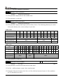
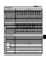
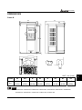
3.5 Specifications for Power Terminals and Control Terminals
Frame B
Power Terminals:
R/L1, S/L2, T/L3, U/T1, V/T2, W/T3,
Models
VFD007F23A
VFD007F43A
VFD007F43H
VFD015F23A
VFD015F43A
VFD015F43H
VFD022F23A
VFD022F43A
VFD022F43H
VFD037F23A
VFD037F43A
VFD037F43H
+1 +2 B1 -
B2
U/T1 V/T2 W/T3
Screw Torque :
18Kgf-cm
Wire Gauge :
18~10AWG
Wire Gauge
, +1, +2/B1, -, B2
Torque
Wire Type
3
12-24 AWG.
(3.3-0.2mm2)
18kgf-cm
(15.6in-lbf)
Control Terminals:
Wire Gauge
Stranded
Copper only,
75℃
Torque
12-24AWG. (3.3-0.2mm2)
4kgf-cm (3in-lbf)
R/L1 S/L2 T/L3
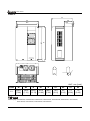
Frame C
Power Terminals:
R/L1, S/L2, T/L3, U/T1, V/T2, W/T3,
POWER
IM
3
, +1, +2/B1, -, B2
Models
Wire Gauge
Torque
Wire Type
VFD055F23A
VFD055F43B
VFD055F43H
VFD075F23A
VFD075F43B
VFD075F43H
VFD110F23A
VFD110F43A
VFD110F43H
VFD150F43A
VFD150F43H
12-8 AWG.
2
(3.3-8.4mm )
30kgf-cm
(26in-lbf)
Stranded
Copper only,
75℃
NOTE
MOTOR
If wiring of the terminal utilizes the wire with a diameter of
6AWG.(13.3mm2), it is thus necessary to use the Recognized
Ring Terminal to conduct a proper wiring.
Control Terminals:
Wire Gauge
12-24AWG. (3.3-0.2mm2)
DELTA ELECTRONICS, INC. ALL RIGHTS RESERVED
3-11
Torque
4kgf-cm (3in-lbf)
VFD-F Series
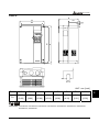
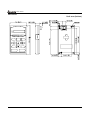
Frame D
Power Terminals:
R/L1, S/L2, T/L3, U/T1, V/T2, W/T3,
, +1, +2, -,
Models
Wire Gauge
Torque
Wire Type
VFD150F23A
VFD185F23A
VFD185F43A
VFD185F43H
VFD220F23A
VFD220F43A
VFD220F43H
VFD300F43A
VFD300F43H
8-2 AWG.
(8.4-33.6mm2)
30kgf-cm
(26in-lbf)
Stranded
Copper only,
75℃
NOTE
POWER
DC (+)
DC ( - )
IM
3
MOTOR
If wiring of the terminal utilizes the wire with a diameter of
1AWG.(42.4mm2), it is thus necessary to use the Recognized
Ring Terminal to conduct a proper wiring.
Control Terminals:
Wire Gauge
Torque
12-24AWG. (3.3-0.2mm2)
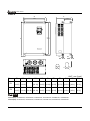
Frame E
4kgf-cm (3in-lbf)
Power Terminals:
R/L1, S/L2, T/L3, U/T1, V/T2, W/T3,
CHARGE
POWER
IM
3
MOTOR
Models
Wire Gauge
VFD300F23A
1/0-4/0 AWG.
2
(53.5-107.2mm )
VFD370F23A
VFD750F43A
VFD750F43H
VFD900F43C
VFD900F43H
VFD370F43A
VFD370F43H
VFD450F43A
VFD450F43H
VFD550F43A
VFD550F43H
3/0-4/0 AWG.
(85-107.2mm2)
Wire Type
200kgf-cm
(173in-lbf)
Stranded
Copper only,
75℃
4/0 AWG.
(107.2mm2)
2
3 AWG. (26.7mm )
2 AWG. (33.6mm2)
1/0-4/0 AWG.
(53.5-107.2mm2)
Control Terminals:
Wire Gauge
57kgf-cm
(49.5in-lbf)
200kgf-cm
(173in-lbf)
Torque
12-24AWG. (3.3-0.2mm2)
3-12
, +1, +2, -,
Torque
4kgf-cm (3in-lbf)
DELTA ELECTRONICS, INC. ALL RIGHTS RESERVED
VFD-F Series
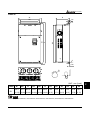
Frame G
Power Terminals:
, +1, +2, -,
R/L1, S/L2, T/L3, U/T1, V/T2, W/T3,
Models
Wire Gauge
Torque
Wire Type
VFD1100F43C
VFD1100F43H
VFD1320F43A
VFD1320F43H
VFD1600F43A
VFD1600F43H
4/0 AWG. - 300MCM
(107.2-152mm2)
300kgf-cm
(260in-lbf)
Stranded
Copper only,
75℃
NOTE
16-4
+1 +2
U/T1 V/T2 W/T3
IM
DC(+) DC(-)
3
MOTOR
31MAX.
70MAX.
R/L1 S/L2 T/L3
POWER
+0
It needs following additional terminal when wiring, and add
insulation sheath on position where following figure shows.
8.2MIN
.
26.5MAX.
Control Terminals:
Wire Gauge
Torque
12-24AWG. (3.3-0.2mm2)
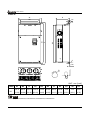
Frame H
4kgf-cm (3in-lbf)
Power Terminals:
R/L1, S/L2, T/L3, U/T1, V/T2, W/T3,
, +1, -,
Models
Wire Gauge
Torque
Wire Type
VFD1850F43A
VFD1850F43H
VFD2200F43A
VFD2200F43H
500 MCM (max)
408kgf-cm
(354 in-lbf)
Stranded
copper only,
75°C
NOTE
12
MI
.2(
)
N.
42.0(MAX.)
23.0(MAX.)
It needs following additional terminal when wiring, and add
insulation sheath on position where following figure shows.
INSULATION SHEATH
WIRE
R/L1 S/L2 T/L3
POWER
+
-
DC (+) DC(-)
U/T1 V/T2 W/T3
Control Terminals:
Wire Gauge
12-24AWG. (3.3-0.2mm2)
DELTA ELECTRONICS, INC. ALL RIGHTS RESERVED
3-13
80.0(MAX.)
42.0(MAX.)
Torque
4kgf-cm (3in-lbf)
3
VFD-F Series
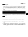
3.6 Wiring Notes: PLEASE READ PRIOR TO INSTALLATION.
1.
2.
! CAUTION: Do not connect the AC power to the U/T1, V/T2, W/T3 terminals, as it
will damage the AC drive.
!
WARNING: Ensure all screws are tightened to the proper torque rating.
3. During installation, follow all local electrical, construction, and safety codes for the
country the drive is to be installed in.
4. Ensure that the appropriate protective devices (circuit breaker or fuses) are connected
between the power supply and AC drive.
5. Make sure that the leads are connected correctly and the AC drive is properly grounded.
(Ground resistance should not exceed 0.1Ω.)
6. Use ground leads that comply with AWG/MCM standards and keep them as short as
possible.
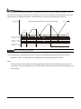
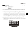
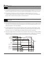
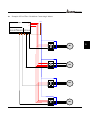
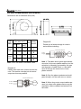
7. Multiple VFD-F units can be installed in one location. All the units should be grounded
directly to a common ground terminal. The VFD-F ground terminals may also be
connected in parallel, as shown in the figure below. Ensure there are no ground loops.
Forward
running
8. When the AC drive output terminals U/T1, V/T2, and W/T3 are connected to the motor
terminals U, V, and W, respectively, the motor will rotate counterclockwise (as viewed
from the shaft ends of the motor) when a forward operation command is received. To
reverse the direction of motor rotation, switch over any of the two motor leads.
9. Make sure that the power source is capable of supplying the correct voltage and
required current to the AC drive.
10. Do not attach or remove wiring when power is applied to the AC drive.
11. Do not inspect components unless inside “CHARGE” lamp is turned off.
12. Do not monitor the signals on the circuit board while the AC drive is in operation.
3-14
DELTA ELECTRONICS, INC. ALL RIGHTS RESERVED
VFD-F Series
13. For the single-phase rated AC drives, the AC power can be connected to any two of the
three input terminals R/L1, S/L2, T/L3. Note: This drive is not intended for the use
with single-phase motors.
14. Route the power and control wires separately, or at 90°angle to each other.
15. If a filter is required for reducing EMI (Electro Magnetic Interference), install it as close
as possible to AC drive. EMI can also be reduced by lowering the Carrier Frequency.
16. If the AC drive is installed in the place where a load reactor is needed, install the filter
close to U/T1, V/T2, W/T3, side of AC drive. Do not use a Capacitor or L-C Filter
(Inductance-Capacitance) or R-C Filter (Resistance-Capacitance), unless approved by
Delta.
17. When using a general GFCI (Ground Fault Circuit Interrupter), select a current sensor
with sensitivity of 200mA or above, and not less than 0.1-second detection time to avoid
nuisance tripping. For the specific GFCI of the AC motor drive, please select a current
sensor with sensitivity of 30mA or above.
18. To improve the input power factor, to reduce harmonics and provide protection from AC
line disturbances (surges, switching spikes, short interruptions, etc.), AC line reactor
should be installed when the power supply capacity is 500kVA or more.
19. There are highly sensitive MOS components on the printed circuit boards. These
components are especially sensitive to static electricity. To prevent damage to these
components, do not touch these components or the circuit boards with metal objects or
your bare hands.
DELTA ELECTRONICS, INC. ALL RIGHTS RESERVED
3-15
3
VFD-F Series
3.7 Motor Operation Precautions
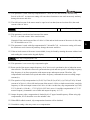
1. When using the AC drive to operate a standard 3-phase induction motor, notice that the
energy loss is greater than for an inverter duty motor.
2. Avoid running a standard induction motor at low speed. Under these conditions, the
motor temperature may rise above the motor rating due to limited airflow produced by
the motor’s fan.
3. When the standard motor operates at low speed, the output load must be decreased.
4. If 100% output torque is desired at low speed, it may be necessary to use a special
“inverter-duty” rated motor.
3-16
DELTA ELECTRONICS, INC. ALL RIGHTS RESERVED
VFD-F Series
CHAPTER 4
DIGITAL KEYPAD OPERATION
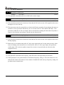
This chapter describes the various controls and indicators found on the digital keypad. The
information in this chapter should be read and understood before performing the start–up
procedures described in the chapter of parameter settings.
ª Description of the Keypad
ª Description of Display
ª Keypad Operation Modes & Programming Steps
DELTA ELECTRONICS, INC. ALL RIGHTS RESERVED
4-1
4
VFD-F Series
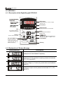
4.1 VFD-PU01
4.1.1 Description of the Digital Keypad VFD-PU01
F
H
U
LED Display
Display frequency, current, voltage
and error, etc.
VFD-PU01
Part Number
Status Display
Display the driver's current status
JOG
By pressing JOG key.
Initiates jog operation.
MODE
Changes between different
JOG
display mode.
Left key
moves cursor to the left
STOP/RESET
UP and DOWN Key
Sets the parameter
number and changes the
numerical data, such as
Master Frequency.
RUN
STOP
RESET
RUN key
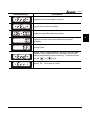
4.1.2 Explanation of Display Message
Display Message
Descriptions
Display the AC drive Master Frequency.
Display the actual operation frequency present at terminals
U/T1, V/T2, and W/T3.
Display voltage (V), Current (A), power factor and feedback
signal (P)
Display the output current present at terminals U/T1, V/T2,
and W/T3.
4-2
DELTA ELECTRONICS, INC. ALL RIGHTS RESERVED
VFD-F Series
Display Message
Descriptions
Display the AC drive forward run status.
The AC drive reverse run status.
Display the specified parameter setting.
Display the actual value stored within the specified
parameter.
External Fault.
Display “End” for approximately 1 second if input has been
accepted. After a parameter value has been set, the new
value is automatically stored in memory. To modify an entry,
use the
or
keys.
Display “Err”, if the input is invalid.
DELTA ELECTRONICS, INC. ALL RIGHTS RESERVED
4-3
4
VFD-F Series
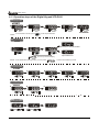
4.1.3 Operation steps of the Digital Keypad VFD-PU01
Selecting mode
START
F
F
F
H
U
F
H
H
H
U
U
U
MODE
MODE
F
H
U
MODE
MODE
MODE
GO START
Note:In the selection mode, press
to set the parameters.
Setting parameters
F
H
U
F
H
U
F
H
U
Success to set parameter.
F
H
U
F
H
U
Input data error
MODE
move to previous display
NOTE:In the parameter setting mode, you can press
MODE
to return the selecting mode.
To shift data
START
F
F
F
F
F
F
H
U
F
H
U
H
U
H
U
F
H
U
H
U
F
H
U
To modify data
F
START
H
U
H
U
H
U
Setting direction
F
H
U
or
or
4-4
DELTA ELECTRONICS, INC. ALL RIGHTS RESERVED
VFD-F Series
4.2 KPF-CC01
For models of VFD-F (HVAC) series
VFD007F43H; VFD015F43H; VFD022F43H; VFD037F43H; VFD055F43H; VFD075F43H;
VFD110F43H; VFD150F43H; VFD185F43H; VFD220F43H; VFD300F43H; VFD370F43H;
VFD450F43H; VFD550F43H; VFD750F43H; VFD900F43H; VFD1100F43H; VFD1320F43H;
VFD1600F43H; VFD1850F43H; VFD2200F43H
NOTE
When KPF-CC01 is connected on AC motor drive, the communication protocol is forced to be 9600, 8,
N, 2. After KPF-CC01 is disconnected, and AC motor drive immediately gets connection with other
controller by RS-485, 1st communication fault may occur due to different communication protocol. AC
motor drive will automatically reset communication protocol as previous parameter setting from 2nd
communication.
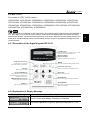
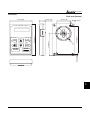
4.2.1 Description of the Digital Keypad KPF-CC01
LCD Display
Indicates frequency, voltage, current, user
defined units, read, and save etc.
Model Number
Status Display
Display the driver 's current status.
JO G Operation key
MODE
Press this key to execute
the JOG frequency operation.
Change between different displ ay mode.
Parameter Unit k ey
Switch the operation command sourc e.
Left key
Moves the cursor left.
UP and DOWN key
Right key
Set the parameter number and
changes the numerical data, such
as Mas ter Frequency.
Moves the cursor right.
PROG/DATA
Us ed to enter programming parameters.
FWD/RE V Direction key
Selec t FWD/REV operation
STOP/RESET
RUN key
Stops AC drive operation or reset the drive
after fault occurred.
Start AC drive operation.
4.2.2 Explanation of Display Message
Display Message
Description
The AC motor drive Master Frequency Command.
The Actual Operation Frequency present at terminals U, V, W.
DELTA ELECTRONICS, INC. ALL RIGHTS RESERVED
4-5
4
VFD-F Series
Display Message
Description
The output current present at terminals U, V, W.
The specified group description.
The specified parameter description and setting
Copy Mode: Press MODE key for about 2~3 seconds in main
page. Use UP/DOWN key to select copy function (Read, Write,
Delete) and LEFT/RIGHT key to select memory address. Total
two blocks are available.
Use UP/DOWN key to confirm copy function. Press PROG/DATA
key to execute.
External Fault.
Input data is accepted.
Input data is invalid.
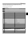
4.2.3 KPF-CC01 Operation Flow Chart
KPF-CC01 Operation Flow Chart
4-6
DELTA ELECTRONICS, INC. ALL RIGHTS RESERVED
VFD-F Series
CHAPTER 5 DESCRIPTION OF PARAMETER SETTINGS
: This parameter can be set during operation.
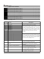
5.1 Group 0: AC Drive Status Parameters
Group 0 is read-only.
00 - 00 Software Version
Factory setting: Read Only
This parameter displays the software version of AC drive.
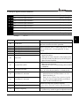
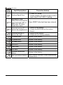
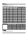
00 - 01 AC Drive Status Indication 1
Factory setting: Read Only
This parameter displays the AC drive status.
Code
00
01
02
03
04
05
06
07
08
09
AC Drive Status
No fault occurred
oc
ov
oH
oL
oL1
EF (external fault)
occ (AC drive IGBT fault )
cF3 (CPU failure)
HPF (hardware protection failure)
10
ocA (over current during acceleration)
11
ocd (over current during deceleration)
12
13
14
15
16
17
18
19
20
21
22
ocn (over current during steady state
operation)
GFF (ground fault)
Lv (under voltage)
cF1
cF2
bb (base block)
oL2 (motor over load 2)
Reserved
codE
EF1 (external emergency stop)
PHL (phase loss)
23
24
25
Lc (Low Current)
FbL(Feedback Loss)
Reserved
DELTA ELECTRONICS, INC. ALL RIGHTS RESERVED
Explanation
over current
over voltage
over temperature
overload
electronic thermal relay
EF-DCM is closed
IGBT short circuit protection
Abnormal A/D reading during self-check
Hardware protection function activated during
self-check.
Output current exceeds protection level during
acceleration
Output current exceeds protection level during
deceleration
Output current exceeds protection level during
steady state operation.
Ground fault protection feature activated
Low input voltage
EEPROM input data is abnormal
EEPROM output data is abnormal
BB is set and activated
Output current exceeds rated motor current
software or password protection
EF1 (a multifunction-DCM is enabled)
Input power lacks phase.
3-phase input power is unbalance and exceeds
specification.
Low current detection during operation.
Feedback signal is abnormal.
5-1
5
VFD-F Series
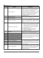
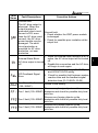
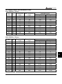
Code
26
27
28
29
30
31
32
33
34
AC Drive Status
FAnP
FF1
FF2
FF3
FF123
FF12
FF13
FF23
Fv
Explanation
Fan Power Fault
Fan 1 Fault
Fan 2 Fault
Fan 3 Fault
Fan 1, 2, 3 Fault
Fan 1, 2 Fault
Fan 1, 3 Fault
Fan 2, 3 Fault
Gate Drive Low Voltage Protect
Factory setting: Read Only
00 - 02 AC Drive Status Indication 2
Display Bit 0~1: 00: Run LED is off and STOP led is on. (AC Drive stopping)
01: Run LED is blink and STOP led is on. (AC Drive deceleration to stop)
10: Run LED is on and STOP led is blink. (AC Drive standby)
11: Run LED is on and STOP led is off. (AC Drive running)
Bit 2: 1: Jog on.
Bit 3~4: 00: Rev LED is off and FWD led is on. (Forward)
01: Rev LED is blink and FWD led is on. (Reverse to Forward)
10: Rev LED is on and FWD led is blink. (Forward to Reverse)
11: Rev LED is on and FWD led is off. (Reverse)
Bit 5-7: Reserved
Bit 8: Master frequency source via communication interface
Bit 9: Master frequency source via analog
Bit10: Running command via communication interface
Bit11: Parameter locked
Bit12~15: Reserved
00 - 03 Frequency Setting
Factory setting: Read Only
This parameter displays the frequency command set by the user.
00 - 04 Output Frequency
Factory setting: Read Only
This parameter displays actual output frequency of the AC drive.
00 - 05 Output Current
Factory setting: Read Only
This parameter displays actual output current of the AC drive.
00 - 06 DC-BUS Voltage
Factory setting: Read Only
This parameter displays DC-BUS voltage of the AC drive.
00 - 07 Output Voltage
Factory setting: Read Only
This parameter displays output voltage of the AC drive.
5-2
DELTA ELECTRONICS, INC. ALL RIGHTS RESERVED
VFD-F Series
00 - 08 Output Power Factor
Factory setting: Read Only
This parameter displays output power factor.
00 - 09 Output Power (kW)
Factory setting: Read Only
This parameter displays output power of the AC drive.
00 - 10 Feedback Signal Actual Value
Factory setting: Read Only
This parameter displays feedback signal value.
00 - 11 Feedback Signal (%)
Factory setting: Read Only
This parameter displays feedback signal value (%).
00 - 12 User Target Value (Low bit) uL 0-99.99
Factory setting: Read Only
00 - 13 User Target Value (High bit) uH 0-9999
Factory setting: Read Only
User Target Value = Actual output frequency (0-04) × User Defined Multiplier (02-10).
Maximum summed display of both parameters is 999999.99.
When User Target Value <=99.99, 00-13=0.
00 - 14 PLC time
Factory setting: Read Only
This parameter displays remaining time of PLC each phase.
00-15 Stall torque output(N.M.)
This parameter shows stall torque output in Newton meter.
DELTA ELECTRONICS, INC. ALL RIGHTS RESERVED
5-3
5
VFD-F Series
5.2 Group 1: Basic Parameters
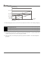
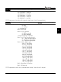
01 - 00 Maximum Output Frequency
Settings
Factory Setting: 60.00
50.00~120.00Hz
This parameter determines the AC drives maximum output frequency. All master frequency
commands set by the keypad or analog inputs are limited by this parameter. The analog commands
(AVI, ACI1 and ACI2) may be scaled to correspond to the output frequency range. (Please refer to
04-09~04-20.)
01 - 01 Maximum Voltage Frequency (Base Frequency)
Settings
Factory Setting: 60.00
0.10~120.00 Hz
This parameter sets the frequency, where the maximum output voltage (Pr. 01-02) will be reached.
The output frequency may exceed this setting, but the output voltage doesn’t increase beyond this
point. This parameter should be set according to the rated frequency of the motor as indicated on the
motor nameplate.
If this parameter setting is smaller than the rated frequency of the motor, nuisance over current faults
or damage to the AC drive may occur.
If this parameter setting is greater than the rated frequency of the motor, the motor will encounter
torque loss.
01 - 02 Maximum Output Voltage
Settings
Factory Setting: 220.0/440.0
230V series: 0.1 ~ 255.0V
460V series: 0.2 ~ 510.0V
This parameter determines the Maximum Output Voltage of the AC drive. This parameter setting
should be set according to rated voltage of the motor as indicated on the motor nameplate. If rated
voltage of the motor is 440V, this parameter must be set to 440V. If rated voltage of the motor is 380V,
this parameter must be set to 380V.
If this setting is greater than the rated voltage of the motor, nuisance over current faults or damage to
the AC drive may occur.
01 - 03 Mid-point Frequency
Settings
Factory Setting: 1.50
0.10~120.00 Hz
This parameter sets the Mid-point Frequency of the V/f curve.
This parameter must meet the following argument. Pr.1-01 >= Pr.1-03 >= Pr.1-05.
5-4
DELTA ELECTRONICS, INC. ALL RIGHTS RESERVED
VFD-F Series
01 - 04 Mid-point Voltage
Settings
Factory Setting: 5.5/11.0
230V series: 0.1 ~ 255.0V
460V series: 0.2 ~ 510.0V
This parameter sets the Mid-point Voltage of the V/f curve.
This parameter must meet the following argument. Pr.1-02 >= Pr.1-04 >= Pr.1-06.
01 - 05 Minimum Output Frequency
Settings
Factory Setting: 1.50
0.10~20.00 Hz
This parameter sets the Minimum Output Frequency of the AC drive. This parameter must be lower
than or equal to the Mid-point frequency
01 - 06 Minimum Output Voltage
Settings
Factory Setting: 5.5/11.0
5
230V series: 0.1 ~ 50.0V
460V series: 0.2 ~100.0V
This parameter sets the Minimum Output Voltage of the AC Drive. The parameter must be lower
than or equal to the Mid-point Voltage.
01 - 07 Upper Bound Frequency
Settings
Factory Setting: 60.00
0.00~120.00 Hz
This parameter will limit the maximum output frequency of AC drive. If slip compensation
(Pr.07-02~07-05) or feedback control (Pr.10-00~10-09) are enabled, the output frequency of AC
drive may exceed the Master Frequency Command, but it will continue to be limited by this
parameter setting.
01 - 08 Lower Bound Frequency
Settings
Factory Setting: 0.00
0.00~120.00 Hz
This parameter will limit the minimum output frequency. Any Master Frequency Command below
Pr.1-08 will result in an output equal to Pr.1-08.
Upon a start command, the drive will accelerate from Pr.1-05 Minimum Output Frequency to the
Master Frequency Command point.
The Lower Bound Frequency setting must be smaller than the Dwell Frequency (Pr.11-08>=01-08).
If lower bound frequency setting is greater than the Dwell Frequency, the AC drive will equalize the
two settings to the Lower Bound point.
DELTA ELECTRONICS, INC. ALL RIGHTS RESERVED
5-5
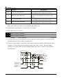
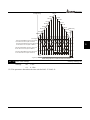
VFD-F Series
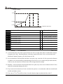
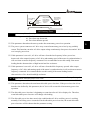
Output voltage
01-02
01-04
01-06
01-05
01-08
01-03 01-01
01-00
Output Frequency
01-07
Factory Setting: 10.0/60.0
Factory Setting: 10.0/60.0
01 - 09 Acceleration Time 1
01 - 10 Deceleration Time 1
01 - 11 Acceleration Time 2
01 - 12 Deceleration Time 2
Factory Setting: 10.0/60.0
01 - 13 Acceleration Time 3
Factory Setting: 10.0/60.0
01 - 14 Deceleration Time 3
Factory Setting: 10.0/60.0
01 - 15 Acceleration Time 4
Factory Setting: 10.0/60.0
01 - 16 Deceleration Time 4
Factory Setting: 10.0/60.0
01 - 17 JOG Acceleration Time
Factory Setting: 10.0/60.0
01 - 18 JOG Deceleration Time
Factory Setting: 10.0/60.0
Settings
0.1~3600.0 Sec
Factory Setting: 10.0/60.0
Unit: 0.1sec
Acceleration time is the time required for the AC drive to ramp from 0 Hz to its Maximum Output
Frequency (Pr.1-00). Deceleration time is the time required for the AC drive to decelerate from
Maximum Output Frequency (Pr.1-00) down to 0 Hz.
An Acceleration or Deceleration time that is too quick, may cause the AC drives protection features
to enable (over-current stall prevention during Accel 06-01 or over-voltage stall prevention 06-00).
If this occurs, the actual Accel/Decel time will be longer than this setting.
Warning: An acceleration or deceleration that is too quick, may cause excess loads on the AC drive
and may permanently damage the drive.
If you want to decelerate the AC drive in short time period, we recommend to add an external brake
module and brake resistor.
You can set 1st to 4th Accel/Decel time via multi-function input terminals 04-00 to 04-07.
5-6
DELTA ELECTRONICS, INC. ALL RIGHTS RESERVED
VFD-F Series
01 - 19 JOG Frequency
Settings
Factory Setting: 6.00
0.0 Hz~120.00 Hz
Unit: 0.1sec
When the JOG function is to be utilized, users need to use the multi-function input terminals (Pr.
04-00 to 04-07 set to 07) or the JOG key on keypad. Once a JOG command is initiated, the AC drive
will accelerate from the Minimum Output Frequency (Pr.01-05) to the JOG frequency (Pr.01-19).
The accel/decel time of the JOG operation is determined by the JOG accel/decel speed (Pr.01-17 and
01-18).
When the drive is in operation, the JOG command is disabled.
01 - 20 S Curve Delay Time in Accel
Factory Setting: 0.00
01 - 21 S Curve Delay Time in Decel
Settings
0.00~2.50sec
5
These parameters enable the S curve. The longer the S curve time period the smoother the transition
between speeds.
01 - 22 Modulation Index
Settings
Factory Setting: 1.00
0.90~1.20
Unit: 0.1
This parameter sets the ratio of the Maximum Output Voltage to the input voltage.
The Maximum Output Voltage (Pr.01-02) is normally limited to the input voltage. With the
Modulation Index parameter, the user is able to increase the output voltage beyond the incoming line
voltage.
A Modulation Index of 1, defines the Maximum Output Voltage (Pr. 1-02) is equal to the input
voltage.
A Modulation index of 1.2, defines the Maximum Output Voltage (Pr. 1-02) is 20% higher than in the
input voltage. Please note, the output voltage wave form will be distorted due to harmonics and may
increase torque ripple and noise in the motor.
DELTA ELECTRONICS, INC. ALL RIGHTS RESERVED
5-7
VFD-F Series
Factory Setting: 01
01 - 23 Accel/Decel Time Unit
Settings
00: Unit is 1 Sec
01: Unit is 0.1 Sec
02: Unit is 0.01 Sec
This parameter sets the resolution of accel/decel time (Pr.01-09 to 01-18).
A high resolution decreases the accel/decel time range as shown in the following chart.
01-23
00
01
02
Accel/Decel time unit
1 Sec
0.1 Sec
0.01 Sec
5-8
Accel/Decel time range
1~36000 Sec
0.1~3600.0 Sec
0.01~360.00 Sec
DELTA ELECTRONICS, INC. ALL RIGHTS RESERVED
VFD-F Series
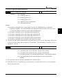
5.3 Group 2: Operation Method Parameters
02 - 00 Source of Frequency Command
Settings
Factory Setting: 00
00: via keypad
01: via analog input AVI
02: via analog input ACI1
03: via analog input ACI2
04: via RS485 serial communication
05: via External Reference
Settings:
00: Frequency command source is the keypad. User may use UP/DOWN keys to adjust the
frequency command. Also if the Multi-Function Input terminals (Pr.04-00 to 04-07) are set to
13 or 14, their function will be the same as the UP/DOWN keys.
5
01: Frequency command source is the analog input terminal AVI.
02: Frequency command source is the analog input terminal ACI1.
03: Frequency command source is the analog input terminal ACI2.
04: Frequency command source is the RS485 serial communication.
05: Frequency command source depends on the setting of Pr. 04-24.
You may use SW2 on the control board to choose between a 0~10V or 0~5V input range. When AVI
is set to 0~5V, the voltage input is limited to 5V maximum. The relationship to frequency is 0V = 0
Hz and 5V = Pr1-00.
02 - 01 Source of Operation Command
Settings
Factory Setting: 00
00: Controlled by the digital keypad
01: Controlled by the external terminals, keypad STOP enabled.
02: Controlled by the external terminals, keypad STOP disabled.
03: Controlled by the RS-485 communication interface, keypad STOP enabled.
04: Controlled by the RS-485 communication interface, keypad STOP
disabled.
This parameter sets the operation command source of the AC drive.
When the AC drive is controlled by an external source, you may select 2-wire or 3-wire operation.
Please refer to Pr.02-05.
DELTA ELECTRONICS, INC. ALL RIGHTS RESERVED
5-9
VFD-F Series
Factory Setting: 00
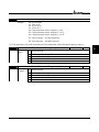
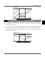
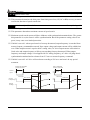
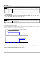
02 - 02 Stop Method
Settings
00:Stop = ramp to stop, E.F. (External Fault) = coast to stop
01:Stop = coast to stop, E.F. = coast to stop
02:Stop = ramp to stop, E.F. = ramp to stop
03:Stop = coast to stop, E.F. = ramp to stop
Ramp: The AC drive decelerates the motor to minimum output frequency according to the
deceleration time setting.
Coast: The AC drive output instantly stops upon command and the motor free spins until it comes to
a complete stop.
External Fault may be enabled by the EF terminal or a Multi-Function terminal. Please refer to
Pr.04-00 to 04-07.
Loss of an ACI signal may cause an E.F condition. Please refer to 02-07.
Output
Frequency
Frequency
Frequency
Output
Frequency
Motor
speed
Motor
Speed
Time
Operation
Command
RUN
Stops according
to deceleration
time
STOP
Operation
Command
Time
Free running
to stop
Ramp
Coast
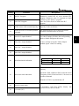
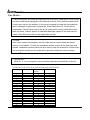
02 - 03 PWM Carrier Frequency Selections
Settings
STOP
RUN
Unit: 1
1~10HP 4000~10000Hz
Factory Setting: 9000Hz
15~30HP 3000~9000Hz
Factory Setting: 6000Hz
≧40HP 2000~6000Hz
Factory Setting: 4000Hz
This parameter sets the carrier frequency of PWM output. The factory setting and setting range
depend on the model type.
When the temperature of the heat sink is greater than its limit, the AC drive will automatic lower the
carrier frequency to avoid over heating the AC drive.
5-10
DELTA ELECTRONICS, INC. ALL RIGHTS RESERVED
VFD-F Series
The Carrier frequency of the PWM output has a signification influence on the electromagnetic noise,
heat dissipation of the AC drive, and the acoustic noise to the motor as shown in the following chart.
Carrier
frequency
Signification
Acoustic
Noise
Minimal
Electromagnetic
Leakage
Heat
Noise
Current
Dissipation
Signification Signification Signification
Minimal Signification
Minimal
Minimal
Minimal
When the carrier frequency is low, current ripple of the AC drive is large. This may result in a current
display value greater than the actual value.
Factory Setting: 00
02 - 04 Forward/Reverse Enable
Settings
00: Forward/Reverse enabled
01: Reverse disabled
5
02: Forward disabled
This parameter enables the direction of the AC drive.
Factory Setting: 00
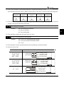
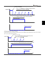
02 - 05 2-wire/3-wire Operation Control Modes
Settings
00: 2-wire (#1), FWD/STOP, REV/STOP
01: 2-wire (#2), RUN/STOP, REV/FWD
02: 3-wire
This parameter sets the operation mode when operating by external terminals.
Please refer to 02-01.
02-05
External Terminal
00 (2-wire #1)
FWD / STOP
REV / STOP
FWD/STOP
FWD :("OPEN":STOP)
REV/STOP
REV: ("OPEN":STOP)
01 (2-wire #2)
RUN / STOP
REV / FWD
RUN/STOP
("CLOSE":FWD)
DCM
F WD :("OPEN":STOP)
("CLOSE":RUN)
REV :("OPEN":FWD)
FWD/REV
DCM
STOP
RUN
FWD/REV
("OPEN":STOP)
REV ("OPEN":FWD)
("CLOSE":REV)
DCM
5-11
("CLOSE":REV)
F WD ("CLOSE":RUN)
EF
02 3-wire
DELTA ELECTRONICS, INC. ALL RIGHTS RESERVED
("CLOSE":REV)
VFD-F
VFD-F Series
Factory Setting: 01
02 - 06 Line Start Lockout
Settings
00: Enabled
01: Disabled
02: If the command to run still remains after
resetting, the inverter will continue to run.
When enabled, the AC drive will not start when powered up with a run command applied. The AC
drive must see the run command transition from stop to run after power up. When Line Start
Lockout is disabled (also known as Auto-Start), the AC drive will start when powered-up with run
commands applied.
Pr02-06=2:
This determines the following matter. The VFD (Variable-Frequency Drive) detects an error message and
eliminates the error. If the command terminal remains running in the external function terminals, you can
simply press the RESET button to make the VFD running again.
Factory Setting: 01
02 - 07 ACI(4~20mA)Loss of ACI Signal
Settings
00: Decelerate to 0Hz
01: E.F.
02: Continue operation by the last frequency command
03: Use loss of ACI Signal Frequency of Pr02-16
This parameter determines the AC drives response to a loss of the ACI input.
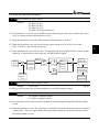
02 - 08 Start-up Display Selection
Settings
Factory Setting: 00
Bit0~1: 00 = F LED
01 = H LED
10 = U LED (special display)
11 = Fwd / Rev
Bit2: 0 = Fwd LED / 1 = Rev LED
Bit3~5: 000 = 1st 7-step
001 = 2nd 7-step
010 = 3rd 7-step
011 = 4th 7-step
100 = 5th 7-step
Bit6~7: Reserved
This parameter determines the display on keypad after each power up.
5-12
DELTA ELECTRONICS, INC. ALL RIGHTS RESERVED
VFD-F Series
To program this parameter the user must first generate a Hex value with the information above. Then
using the Hex to Decimal conversion to find the corresponding Decimal value and enter it into this
parameter.
For example, a setting of 21 (decimal 21= hex 010101) will display the “H” and “REV” LEDs and
the cursor will stay at the 3rd 7-step display upon power up.
When setting to U LED, please refer to 02-09.
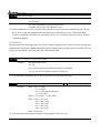
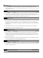
02 - 09 Special Display
Settings
Factory Setting: 00
00: A displays output current of AC drive
01: U displays DC-Bus voltage of AC drive
02: E displays RMS of output voltage
03: P displays feedback signal
04: PLC display auto procedure state
05: T displays heat sink’s temperature
06: The keypad’s screen displays both target value and feedback value
controlled by PID (Proportional–Integral–Derivative controller (PID
controller)).
This parameter chooses the display on the keypad immediately following the “U” user defined
setting.
“MODE” key will scroll from “F”, “H”, “U”, (Pr. 02-09), FWD, and back to “F”.
Users may also use the “LEFT” key on the digital keypad to switch display content.
When Pr02-09 is set to be 6, the keypad’s screen displays both target value and feedback value
controlled by PID as shown below.
F
H
U
0.0 0.0
Target
Value
目標值
Feedback
Value
回授值
DELTA ELECTRONICS, INC. ALL RIGHTS RESERVED
5-13
5
VFD-F Series
02 - 10 User Defined Coefficient
Settings
Factory Setting: 1.00
0.01~160.00
Unit: 0.01
When this parameter is set, the “H “display value = actual output frequency of AC drive x 02-10.
If output frequency of AC drive is 90Hz, set 02-10 to 2.5. When H LED lights, the value on the
display is 225.00.
02 - 11 Flying Start
Settings
Factory Setting: 00
00: Disable
01: Enable (DC brake disabled)
When the AC drive starts into a running motor (Flying Start), it may cause an over current on the
drive and may damage the motor. Using speed search upon start-up will allow the drive to slowly
find the motor speed, smoothly take control of the motor, and bring it to command speed.
If the Flying Start feature is enabled upon start-up, the DC brake 08-01 will be disabled.
02 - 12 Flying Start Frequency
Settings
Factory Setting: 00
00: Begin search from Master Frequency Command
01: Begin search from Maximum Frequency (Pr.01-00)
02 - 13 Master Frequency Memory Setting
Settings
Factory Setting: 01
00: Do not remember the last known frequency
01: Remember the last known frequency
If this parameter is set to 00: The AC drive will not store the last known master frequency command,
after power is removed.
If this parameter is set to 01: The AC drive will memorize the last known master frequency
command after power off. Upon power up the last known frequency is displayed.
After a fault, the AC drive will always remember the last know master frequency command.
This feature is only enabled when Pr. 02-00 is set for 0 or 4.
5-14
DELTA ELECTRONICS, INC. ALL RIGHTS RESERVED
VFD-F Series
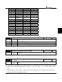
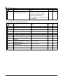
02-14 Source of Second Frequency Command
Setting
Range
00
01
02
03
04
05
Factory
Setting
00
Master Frequency Setting is controlled by PID
controller.
Master frequency is controlled by an external terminal via analog input
AVI: DC 0~+10V.
Master frequency is controlled by an external terminal via analog input
ACI1: DC 4~ 20mA.
Master frequency is controlled by an external terminal via analog input
ACI2: DC 4~ 20mA
Master frequency is handled via RS485 serial
communication (RJ-11).
External Reference Master frequency via External Reference.
5
This parameter sets the source of inverter’s second frequency.
02-15 Source of Second Operation Command
Setting
Range
Factory Setting
00
00 Controlled by the digital keypad
01 Controlled by the external terminals, keypad STOP enabled.
02 Controlled by the external terminals, keypad STOP disabled
Controlled by the RS-485 communication interface keypad STOP
03
enabled.
Controlled by the RS-485 communication interface keypad STOP
04
disabled.
This parameter sets the source of inverter’s second operation command.
Factory Setting
02-16 Loss of ACI Signal
Setting
Range
0.00-Highest operational frequency
This parameter sets the loss of ACI signal
DELTA ELECTRONICS, INC. ALL RIGHTS RESERVED
5-15
0.00
VFD-F Series
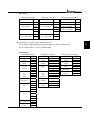
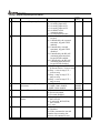
5.4 Group 3: Output Function Parameters
03 - 00 Multi-function Output terminal 1 (Relay 1)
Factory Setting: 00
03 - 01 Multi-function Output terminal 2 (Relay 2)
Factory Setting: 00
03 - 02 Multi-function Output terminal 3 (Relay 3)
Factory Setting: 00
03 - 03 Multi-function Output terminal 4 (Relay 4)
Factory Setting: 00
03 - 04 Multi-function Output terminal 5 (Relay 5)
Factory Setting: 00
03 - 05 Multi-function Output terminal 6 (Relay 6)
Factory Setting: 00
03 - 06 Multi-function Output terminal 7 (Relay 7)
Factory Setting: 00
03 - 07 Multi-function Output terminal 8 (Relay 8)
Factory Setting: 00
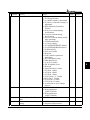
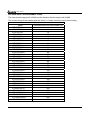
Setting Range 00-43
Setting Functions
00
No function
01
02
03
04
05
06
07
08
09
10
11
12
13
14
15
16
Motor No. 1
Motor No. 2
Motor No. 3
Motor No. 4
Motor No. 5
Motor No. 6
Motor No. 7
Motor No. 8
Auxiliary 1 output
Auxiliary 2 output
Auxiliary 3 output
Auxiliary 4 output
Auxiliary 5 output
Auxiliary 6 output
Auxiliary 7 output
Indication during operation
17
Master frequency
attained
18
Zero Speed (including shutdown)
19
Over-torque
20
External Fault
Descriptions
All unused terminals should be set to 00, to assure
they have no effect on derive operation.
When starting circulative control, AC drive will
automatic set this parameter by 11-01 ~ 11-03. If
there is only one motor available to operate while
running circulative control, the circulative control
will stop. That means the motor will not be
switched.
Parameter value 20 to 26 program Multi-Function
Input Terminals (Pr.04-00~Pr.04-07) to correspond
with the AC drive multi-function output terminals
Pr.03-00 to 03-07 (settings 09-15).
The corresponding output will be closed during
operation (including DC brake time).
The corresponding output will be closed when
output frequency reaches master frequency
command.
The corresponding output will be closed when the
AC drive has no output voltage signal.
The corresponding output relay will be closed when
the AC drives output current exceeds the
over-torque detection level 06-04.
The corresponding output will be closed when the
EF is enabled. (Pr. 4-00 to 4-07)
5-16
DELTA ELECTRONICS, INC. ALL RIGHTS RESERVED
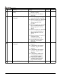
VFD-F Series
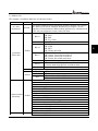
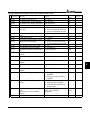
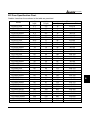
Setting Functions
21
Low voltage detection
22
Operation Mode indication
23
Fault Indication
24
Master Frequency Attained 1
25
Master Frequency Attained 2
26
Over Temperature indication
27
Drive Ready
28
External Emergency Stop (EF1)
29
Software brake output
30
OL or OL1 overload warning
31
Dwell indication (sleep)
32
Low current indication
33
PID feedback error indication
34
PLC Program Running
35
PLC Program Step Completed
36
PLC Program Completed
37
PLC Operation Paused
38
Loss of an ACI signal Indication
39
HOA-Hand mode indication
DELTA ELECTRONICS, INC. ALL RIGHTS RESERVED
Descriptions
The corresponding output will be closed when the
DC Bus voltage drops below our threshold. The
keypad will display “Lu”.
The corresponding output will be closed when the
AC drives “Operation Command” is controlled by
the external terminals.
The corresponding output will be closed when AC
drive has experienced a fault.
The corresponding output will be closed when the
AC drives output frequency exceeds (Pr.03-08)
Master Frequency Attained 1.
The corresponding output will be closed when the
AC drives output frequency exceeds (Pr.03-09)
Master Frequency Attained 2.
The corresponding output will be closed when the
AC drive temperature exceeds its rating.
The corresponding output will be closed the when
the AC drive is ready and has no faults.
The corresponding output will be closed when
multi-function input terminals (Pr.04-00 to 04-07)
are set to emergency stop and then activated.
The corresponding output will be closed when the
AC drives DC bus voltage exceeds (Pr.08-19) the
brake level.
The corresponding output will be closed upon an
overload (OL or OL1) fault.
The corresponding output will be closed when the
AC drive is in a Dwell status (Pr.11-07).
The corresponding output will be closed when the
AC drives output current is lower than the Low
Current setting (Pr.06-08).
The corresponding output will be closed when the
PID feedback signal has an error.
The Output will be activated when PLC Program is
running.
The Output will be activated for 0.5 sec when each
multi-step speed is attained.
The output will be activated for 0.5 sec when the
PLC program cycle has completed
The output will be activated when PLC operation is
paused.
When there is a loss of an ACI signal indication, the
corresponding relay output will be closed.
Under the Hand mode indication of HOA mode, the
corresponding relay output will be closed.
5-17
5
VFD-F Series
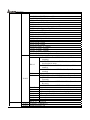
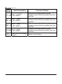
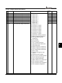
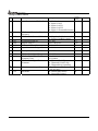
Setting Functions
Descriptions
Under the Off mode indication of HOA mode, the
corresponding relay output will be closed.
Under the Automatic mode indication of HOA
41
HOA-Auto mode indication
mode, the corresponding relay output will be
closed.
When Fire mode indication is activated, the
42
Fire mode indication
corresponding relay output will be closed.
Under the Bypass fire mode indication, the
43
Bypass fire mode indication
corresponding relay output will be closed.
The VFD-F has two form C relays (multi-function output 1 and 2). There is an optional External
Relay Card with 6 NO contact relays (multi-function outputs 3-8).
40
HOA-Off mode indication
External relay specifications = 8A/250VAC or 5A/30VDC.
Relay delay time is 5~10 msec.
Factory Setting: 0.00
03 - 08 Master Frequency Attained 1
03 - 09 Master Frequency Attained 2
Settings
0.00~120.00 Hz
Unit: 0.01
An output relay may be programmed to activate when the output frequency exceeds the desired
attained frequency setting of these two parameters.
There is a 2Hz window of operation. If the master frequency attained is 20Hz and the output
frequency exceeds 20Hz, the corresponding output relay will be “closed”. When the output
frequency is less than 18Hz, the corresponding output relay will be “opened” as the following
diagram shows.
Frequency
2Hz
2Hz
2Hz
4Hz
Master
frequency 1
Frequency
command
Master
frequency 2
Time
Output frequency
Master frequency
2 attained
Master frequency
1 attained
Master frequency
attained
5-18
DELTA ELECTRONICS, INC. ALL RIGHTS RESERVED
VFD-F Series
03 - 10 Analog Output 1, (AFM1) 0~10Vdc
Factory Setting: 00
03 - 11 Analog Output 2, (AFM2) 0/4~ 20mA
00: Output frequency
Settings
01: Output current
02: Output voltage
03: Frequency command
04: Power factor loading
Factory Setting: 01
These parameters select the content of the analog output signals AFM1 and AFM2.
Setting 00: 0-10V = 0 - (Pr.01-00)
Setting 01: 0-10V = 0 - (2.52.0 x rated current)
Setting 02: 0-10V = 0 - (Pr.01-02)
5
Setting 03: 0-10V = 0 - Master Freq. command
Setting 04: 0-10V = 0.0 - output power factor 1.0
When using 0-20mA output, please refer to Pr. 3-14.
Maximum impedance loading of analog output 2 (AFM2) can’t be greater than 500 ohms.
03 - 12 Analog Output Gain 1
Factory Setting: 100
03 - 13 Analog Output Gain 2
Settings
Factory Setting: 100
01~200%
This parameter is to determine analog output gain.
The analog output is limited to 10V and 20mA. The gain is designed to offer a normally small output
signal to be enlarged for easier viewing on a meter.
Factory Setting: 01
03 - 14 Analog Output 2 Selection
00: 0~20mA
Settings
01: 4~20mA
This parameter selects the output range of Analog Output 2 (AFM2).
DELTA ELECTRONICS, INC. ALL RIGHTS RESERVED
5-19
VFD-F Series
Factory Setting: 00
03 - 15 DC Fan Control
00: Fan runs on power up.
Settings
01: Fan begins upon a RUN command. Fan stops 1 minute after a STOP
command.
02: Fan begins upon a RUN command. Fan stops after a STOP command
03: Fan is controlled by temperature. Approximately a 60°C temperature will
start the fan.
04: Unusual Fan status warning, inverter continues to run.
(This setting is only available in the existing firmware v.3.104,
the new released version v.1.302 and the versions above v.1.302)
This parameter determines DC fan control method.
5-20
DELTA ELECTRONICS, INC. ALL RIGHTS RESERVED
VFD-F Series
5.5 Group 4: Input Function Parameters
04 - 00 Multi-function Input terminal 1
Factory Setting: 01
04 - 01 Multi-function Input terminal 2
Factory Setting: 02
04 - 02 Multi-function Input terminal 3
Factory Setting: 03
04 - 03 Multi-function Input terminal 4
Factory Setting: 04
04 - 04 Multi-function Input terminal 5
Factory Setting: 05
04 - 05 Multi-function Input terminal 6
Factory Setting: 07
04 - 06 Multi-function Input terminal 7
Factory Setting: 08
04 - 07 Multi-function Input terminal 8
Factory Setting: 09
Settings
00~43
5
Setting
Functions
00
No function
01
02
03
04
05
Multi-Speed terminal 1
Multi-Speed terminal 2
Multi-Speed terminal 3
Multi-Speed terminal 4
Reset (NO)
06
Reset (NC)
07
Jog operation (JOG)
08
Accel/Decel disable
09
Accel/Decel 2 selection
10
Accel/Decel 3 selection
11
B.B. (NO) input
12
B.B. (NC) input
13
Increase Frequency
DELTA ELECTRONICS, INC. ALL RIGHTS RESERVED
Descriptions
All unused terminals should be set to 00, to assure
they have no effect on drive operation.
Allows selection of the 15 multi-step speeds. Please
refer to 05-00 to 05-14 to program the 15 step
speeds.
Clears (Reset) a fault and returns the AC drive to
normal operation.
When the AC Drive doesn’t work properly, this
terminal and the Stop/Reset key on the keypad
share the same function.
This terminal and the JOG key on the keypad
share the same function.
When the AC Drive is functioning, this terminal
is disabled.
It stops the acceleration or deceleration of the AC
drive. AC drive then maintains a constant speed.
You can combine these two terminals and
choose between Acel/Decel time 1 to 4 in
Pr01-09 to Pr01-16.
Don’t do Accel/Decel time selection, but the
AC drive choose automatically Accel/Decel
time 1 as the Accel/Decel time
Enables the base block (pause) function.
Please refer to Pr.08-08, for base block functions.
This terminal shares the same function as the
Up/Down key on the keypad to adjust the master
5-21
VFD-F Series
Setting
Functions
14
Decrease Frequency
15
Emergency stop (NO)
16
Emergency stop (NC)
17
AVI(open), ACI1(close)
18
KEYPAD(open), EXT(close)
19
PID disable
20
21
22
23
24
25
26
27
28
29
30
Auxiliary 1 input
Auxiliary 2 input
Auxiliary 3 input
Auxiliary 4 input
Auxiliary 5 input
Auxiliary 6 input
Auxiliary 7 input
Motor No.1 output disable
Motor No.2 output disable
Motor No.3 output disable
Motor No.4 output disable
31
All motor outputs disable
Descriptions
frequency command.
This terminal is only available when the AC
drive is functioning. This terminal is disabled
wile the AC drive is not functioning
When this terminal is working, master frequency
can be adjusted Up/Down at the real output
frequency. The adjusting rate of master
frequency command is related to the
Accel/Decel time.
Generates an external fault (EF1). The function is
identical to the external terminal (EF).
External selection of the Master Frequency
command. (Analog input AVI = terminal open) or
(ACI1 = terminal closed). This setting over-rides
Pr.02-00.
External selection of the Operation Command
Source. (Keypad = terminal open) or (External
terminals = terminal closed). This setting is
valid when Pr.02-01 is set to 00. Otherwise,
the Operation Command Source will follow
the setting in Pr.02-01.
When this terminal is set, the master
frequency command from Pr02-01 is
automatically disabled.
Disable PID feedback control and operate via
Master Frequency Command source Pr.02-00.
Parameter value 20 to 26 program Multi-Function
Input Terminals (Pr.04-00~Pr.04-07) to correspond
with the AC drive multi-function output terminals
Pr.03-00 to 03-07 (settings 09-15).
When multiple motors are controlled by an AC
drive, these settings will allow the corresponding
motor to disable and ignore this motor. AC drive
will not accept a “Motor Output Disabled” signal
when it is running.
When multiplex motors are in circulative control
mode, this terminal can stop the motor that power
supply is not from AC drive and set the circulative
control mode disable. Now only the motor in
running keeps running.
5-22
DELTA ELECTRONICS, INC. ALL RIGHTS RESERVED
VFD-F Series
Setting
Functions
Descriptions
32
Run PLC Program
33
Pause PLC Program
34
Enable source of the second frequency
35
Enable the source of second operation
command
36
Motor No.5 output disabled
37
Motor No.6 output disabled
38
Motor No.7 output disabled
39
Motor No.8 output disabled
Parameter value 32 programs Multi-Function Input
Terminal to enable the AC drive internal PLC
program. Parameter value 33 programs an input
terminal to pause the PLC program.
Note: Pr.05-00 to Pr.05-16 defines the PLC
program.
This terminal allows you to choose the master
frequency or the second one.
This terminal allows you to choose the master
operation command or the second one.
When multiple motors are controlled by an AC
drive, these settings will allow the corresponding
motor to disable and ignore this motor.
AC drive will not accept the “Motor Output
Disabled signal” when it is running.
This terminal enables HOA function.
40
HOA-Hand mode indication
MI41 ON
MI41 OFF
MI40 ON
Off mode
Hand mode
MI40 OFF
Auto mode
Off mode
Pr02-00 Refer to Pr02-00 for the source of
frequency
41
HOA-Auto mode indication
Auto mode:Pr02-14 Refer to Pr02-14 for the source
of frequency. Pr02-15 Refer to Pr02-15 for source of
operation command
Off mode: AC Drive is permanently off.
42
(NO) Fire mode (NO)
In accordance with Pr11-15[Fire Mode], this
terminal can start the Fire Mode
43
Fire mode (NC)
DELTA ELECTRONICS, INC. ALL RIGHTS RESERVED
5-23
5
VFD-F Series
Factory Setting: 01
04 - 08 Digital Input Terminal Response Time
Settings
01~20
This parameter selects the response time of digital input terminals MI1 to MI8, EF, REV and FWD.
AC drive will scan the digital input terminals once every 2msec. During each scan the drive will
check the status of each terminal (open or closed).
In noisy environments, it would be advantageous to verify the terminal status several times before
executing a new command, nearly eliminating false signals.
Example: If Pr.04-08 is set to 4, the AC drive will confirm the terminal status (4+1 = 5) 5 times
before a change is made. This correlates to an 8~10msec time response from input command to
execution.
It is not recommended to set this parameter to 00, since interference may cause improper operation
of the AC drive.
04 - 09 AVI Minimum Voltage
Factory Setting: 0.0
04 - 10 AVI Maximum Voltage
Factory Setting: 10.0
Settings
0.0 ~ 10.0V
Unit: 0.1
04 - 11 AVI Minimum Frequency (percentage of Pr.1-00)
Factory Setting: 0.00
04 - 12 AVI Maximum Frequency (percentage of Pr.1-00)
Factory Setting: 100.00
Settings
0.00~100.00%
Unit: 0.01
04 - 13 ACI1 Minimum Current
Factory Setting: 4.0
04 - 14 ACI1 Maximum Current
Factory Setting: 20.0
Settings
0.0 ~ 20.0mA
Unit: 0.1
04 - 15 ACI1 Minimum Frequency (percentage of Pr.1-00)
Factory Setting: 0.00
04 - 16 ACI1 Maximum Frequency (percentage of Pr.1-00)
Factory Setting: 100.00
Settings
0.0~100.0%
Unit: 0.01
04 - 17 ACI2 Minimum Current
Factory Setting: 4.0
04 - 18 ACI2 Maximum Current
Factory Setting: 20.0
Settings
0.0 ~ 20.0mA
Unit: 0.1
5-24
DELTA ELECTRONICS, INC. ALL RIGHTS RESERVED
VFD-F Series
04 - 19 ACI2 Minimum frequency (percentage of Pr.1-00)
Factory Setting: 0.00
04 - 20 ACI2 Maximum frequency (percentage of Pr.1-00)
Factory Setting: 100.00
Settings
0.00~100.00%
Unit: 0.01
The above parameters are used to set the analog input reference values. The min and max
frequencies are based on Pr.01-00 (during open-loop control) or the PID reference value Pr.10-01
(during PID close-loop control).
Please refer to the following diagram for more details:
01-00, 10-10
5
04-12
04-16
04-11
04-15
04-19
04-09
04-13
04-17
04-10
04-14
04-18
Analog
input
Example: Using the AVI (0~10V) as the target source and ACI1 (4~20mA corresponds to 0~5Pa)
and ACI2 (0~10mA corresponds to 0~4Pa) as the feedback location for a pressure sensor connected.
If your target value is between 3~7Pa (Set Pr.10-01 to 10, other parameters settings refer Pr.10-01 to
set as shown in the following diagram and then setting the PID feedback relative parameters.) If
setting AVI to 7.5V, pressure sum of ACI1 and ACI2 could be controlled at 6Pa.
DELTA ELECTRONICS, INC. ALL RIGHTS RESERVED
5-25
VFD-F Series
Pressure Pa
10-10=10.0 Pa
04-12=70
AVI
04-16=50
ACI2
04-20=40
ACI1
04-11=30
04-15=0
04-19=0
04-9=0V 04-13=4mA
04-17=0mA
04-18=10mA
Analog
input
When analog input current of ACI1/ACI2 is lower than Pr.04-13/Pr.04-17, EF warning will pup-up.
04 - 21 Analog Input Delay AVI
Factory Setting: 0.50
04 - 22 Analog Input Delay ACI1
Factory Setting: 0.50
04 - 23 Analog Input Delay ACI2
Factory Setting: 0.50
Settings
0.00 ~ 10.00 Sec
Unit: 0.01
This parameter selects the time constant for the analog input signal filter. A properly adjusted time
constant may help filter noise on the analog input terminals.
If the input delay is set too long, the system may experience oscillation. Be careful setting these
parameters.
5-26
DELTA ELECTRONICS, INC. ALL RIGHTS RESERVED
VFD-F Series
04 - 24 Summation of External Frequency Sources
00: No functions
Settings
01: AVI+ACI1
02: ACI1+ACI2
03: ACI2+AVI
04: Communication master frequency +AVI
05: Communication master frequency +ACI1
06: Communication master frequency +ACI2
Factory Setting: 00
07: First frequency + Second Frequency
08: First frequency - Second Frequency
This parameter selects the terminals used for summation of the External Frequency Sources.
Factory Setting
00
04-26 Summation of Second External Frequency Source Factory Setting
00
04-25 Summation of First External Frequency Source
Setting
Range
00 Digital Keypad
01
02
03
04
Setting
Range
AVI External Terminal AVI
External Terminal ACI1
External Terminal ACI2
RS-485 communication interface
00 Digital Keypad
01
02
03
04
External Terminal AVI
External Terminal ACI1
External Terminal ACI2
RS-485 Communication Interface
DELTA ELECTRONICS, INC. ALL RIGHTS RESERVED
5-27
5
VFD-F Series
5.6 Group 5: Multi-step Speed Frequency Parameters
05 - 00 1st Step Speed Frequency
Factory Setting: 0.00
05 - 01 2nd Step Speed Frequency
Factory Setting: 0.00
05 - 02 3rd Step Speed Frequency
Factory Setting: 0.00
05 - 03 4th Step Speed Frequency
Factory Setting: 0.00
05 - 04 5th Step Speed Frequency
Factory Setting: 0.00
05 - 05 6th Step Speed Frequency
Factory Setting: 0.00
05 - 06 7th Step Speed Frequency
Factory Setting: 0.00
05 - 07 8th Step Speed Frequency
Factory Setting: 0.00
05 - 08 9th Step Speed Frequency
Factory Setting: 0.00
05 - 09 10th Step Speed Frequency
Factory Setting: 0.00
05 - 10 11th Step Speed Frequency
Factory Setting: 0.00
05 - 11 12th Step Speed Frequency
Factory Setting: 0.00
05 - 12 13th Step Speed Frequency
Factory Setting: 0.00
05 - 13 14th Step Speed Frequency
Factory Setting: 0.00
05 - 14 15th Step Speed Frequency
Factory Setting: 0.00
Settings
0.00~120.00 Hz
Unit: 0.01
The Multi-Function Input Terminals (refer to Pr.04-00 to 04-07) are used to select one of the AC
drive Multi-Step speeds. The speeds (frequencies) are determined by Pr.05-00 to 05-14 shown
above.
Factory Setting: 00
05 - 15 PLC Mode
Settings
00
Disable PLC operation
01
Execute one program cycle
02
Continuously execute program cycles
03
Execute one program cycle step by step
04
Continuously execute program cycles step by step
This parameter selects the mode of PLC operation for the AC drive. The AC drive will change
speeds and directions according to the user’s desired programming.
5-28
DELTA ELECTRONICS, INC. ALL RIGHTS RESERVED
VFD-F Series
Example 1 (Pr.05-15 = 1): Execute one cycle of the PLC program. Its relative parameter settings are:
Pr.05-00 to 05-14:
1st to 15th step speed (sets the frequency of each step speed)
Pr.04-00 to 04-07:
Multi-Function Input Terminals (set one multi-function terminal as 32 PLC auto-operation).
Pr.03-00 to 03-07:
Multi-Function Output Terminals (set a Multi-Function Terminal as
34-PLC running indication, 35-PLC step completed or 36-PLC program
completed).
Pr.05-16:
Direction of operation for the 1st to 15th step speed.
Pr.05-17 to 05-31:
Operation time setting of the 1st to 15th step speed.
5
Program operation
command
Program operation
indication
Step operation
indication
Program operation
fulfillment indication
Note: The above diagram shows one complete PLC cycle. To restart the cycle, turn the PLC program off
and on again.
Example 2 (Pr.05-15 = 2): Continuously executes program cycles:
The diagram above shows the PLC program stepping through each speed. Set Pr.05-15 to 2 continuously
executes the program. To stop the PLC program, one must either pause the program or turn it off. (Refer
to Pr.04-00 to 04-07 values 32 and 33).
Example 3 (Pr.05-15 = 3) Execute one cycle step by step:
DELTA ELECTRONICS, INC. ALL RIGHTS RESERVED
5-29
VFD-F Series
The example below shows how the PLC can perform one cycle at a time, within in a complete cycle.
Each step will use the accel/decel times in Pr.01-09 to Pr.01-16. It should be noticed that the time each
step spends at its intended frequency is diminished, due to the time spent during accel/decel.
Frequency
PLC operation execution one cycle step by step
05-03
05-02
05-01
05-00
1
05-17
Program operation
command
OFF
Program operation
indication
OFF
2
t
05-18
3
05-19
t
4
t
Time
05-20
ON
ON
ONON
ON
Step operation
OFF
indication
Factory Setting: 00
05 - 16 PLC Forward/Reverse Motion
Settings
00 to 32767
This parameter controls the direction of motion for the Multi-Step Speeds Pr.05-00 to Pr.05-14
during PLC mode. All other direction commands are invalid during the PLC mode.
Note:
The equivalent 15-bit number is used to program the forward/reverse motion for each of the 15
speed steps. The binary notation for the 15-bit number must be translated into decimal notation and
then entered.
5-30
DELTA ELECTRONICS, INC. ALL RIGHTS RESERVED
VFD-F Series
Weights
Bit 15 14 13 12 11 10 9 8
7
6
5
4
3
2
1
0
0=Forward
1=Reverse
Direction of 1st speed for Pr.05-00
Direction of 2nd speed for Pr.05-01
Direction of 3rd speed for Pr.05-02
Direction of 4th speed for Pr.05-03
Direction of 5th speed for Pr.05-04
Direction of 6th speed for Pr.05-05
Direction of 7th speed for Pr.05-06
Direction of 8th speed for Pr.05-07
Direction of 9th speed for Pr.05-08
Direction of 10th speed for Pr.05-09
Direction of 11th speed for Pr.05-10
Direction of 12th speed for Pr.05-11
Direction of 1 3th speed for Pr.05-12
Direction of 14th speed for Pr.05-13
Direction of 15th speed for Pr.05-14
0=Forward
1=Reverse
Weights
Bit
0
1
0
0
1 1
0 0
0
1
1
1
0
0
1
0
Direction of Pr.05-00, 1st speed = Forward
Direction of Pr.05-01,2nd speed=Reverse
Direction of Pr.05-02 ,3rd speed=Forward
Direction of Pr.05-03 ,4th speed=Forward
Direction of Pr.05-04 ,5th speed=Reverse
Direction of Pr.05-05,6th speed=Reverse
Direction of Pr.05-06,7th speed=Reverse
Direction of Pr.05-07,8th speed=Forward
Direction of Pr.05-08,9th speed=Forward
Direction of Pr.05-09,10th speed=Forward
Direction of Pr.05-10,11th speed=Reverse
Direction of Pr.05-11,12th speed=Reverse
Direction of Pr.05-12, 13th speed=Forward
Direction of Pr.05-13,14th speed=Forward
14
13
Direction of Pr.05-14,15th speed=Reverse
2
1
The setting value = bit14x2 + bit13x2 +....+bit2x2 +bit1x2 +bit0x2
14
11
10
6
5
4
1
= 1x2 + 1x2 +1x2 +1x2 +1x2 +1x2 +1x2
=16384+2048+1024+64+32+16+2
=19570
Setting 05-16 =19570
NOTE:
14
2 =16384
9
2 =512
4
2 =16
13
2 =8192
8
2 =256
3
2 =8
12
2 =4096
7
2 =128
2
2 =4
DELTA ELECTRONICS, INC. ALL RIGHTS RESERVED
11
2 =2048
6
2 =64
1
2 =2
5-31
10
2 =1024
5
2 =32
0
2 =1
0
5
VFD-F Series
05 - 17 Time Duration of 1st Step Speed
Factory Setting: 0.0
05 - 18 Time Duration of 2nd Step Speed
Factory Setting: 0.0
05 - 19 Time Duration of 3rd Step Speed
Factory Setting: 0.0
05 - 10 Time Duration of 4th Step Speed
Factory Setting: 0.0
05 - 21 Time Duration of 5th Step Speed
Factory Setting: 0.0
05 - 22 Time Duration of 6th Step Speed
Factory Setting: 0.0
05 - 23 Time Duration of 7th Step Speed
Factory Setting: 0.0
05 - 24 Time Duration of 8th Step Speed
Factory Setting: 0.0
05 - 25 Time Duration of 9th Step Speed
Factory Setting: 0.0
05 - 26 Time Duration of 10th Step Speed
Factory Setting: 0.0
05 - 27 Time Duration of 11th Step Speed
Factory Setting: 0.0
05 - 28 Time Duration of 12th Step Speed
Factory Setting: 0.0
05 - 29 Time Duration of 13th Step Speed
Factory Setting: 0.0
05 - 30 Time Duration of 14th Step Speed
Factory Setting: 0.0
05 - 31 Time Duration of 15th Step Speed
Factory Setting: 0.0
Settings
0.0 to 65500
Unit: 1 /0.1sec
From Pr.05-17 to Pr.05-31 correspond to operation time of each step speed defined by Pr.05-00 to
Pr.05-14. The maximum setting 65500 seconds will be displayed as t6550. If it shows t6550, that
means 6550 seconds.
Note: If a parameter is set to “00” (0 sec), the corresponding step will be skipped. This is commonly used
to reduce the number of program steps.
5-32
DELTA ELECTRONICS, INC. ALL RIGHTS RESERVED
VFD-F Series
05-07
Frequency
05-06
05-08
05-05
05-09
05-04
05-10
05-03
05-11
05-02
05-12
05-01
JOG Freq.
05-13 01-19
05-00
05-14
Master Speed
2 3 4 5 6 7 8 9 1011 12 131415
Run Signal
ON
1st step speed Multi-function Terminal
Pr.04-00 to Pr.04-07 (MI1 to MI8 1)
2nd step speed Multi-function Terminal
Pr.04-00 to Pr.04-07 (MI1 to MI8 2)
OFF
ON
OFF
3rd step speed Multi-function Terminal
Pr.04-00 to Pr.04-07 (MI1 to MI8 3)
OFF
4th step speed Multi-function Terminal
Pr.04-00 to Pr.04-07 (MI1 to MI8 4)
OFF
ON
ON
ON
ON
ON
ON
ON
ON
ON
ON
5
ON
ON
ON
OFF
ON
Jog Freq.
Multi-Step Speed via External Terminals
Factory Setting: 00
05 - 32 Time Unit Settings
Settings
00
1 Sec
01
0.1 Sec
This parameter determines the time unit for Pr.05-17~Pr.05-31.
DELTA ELECTRONICS, INC. ALL RIGHTS RESERVED
5-33
VFD-F Series
5.7 Group 6: Protection Function Parameters
Factory Setting: 390.0/780.0
06 - 00 Over-voltage Stall Prevention
230V series: 330.0 ~ 410.0VDC
Settings
460V series: 660.0 ~820.0VDC
00: Disable
This parameter selects the voltage level for the Over-Voltage Stall Prevention function.
During decelerations, the DC bus voltage may exceed its maximum allowable value due to motor
regeneration. When this function is enabled, the AC drive will stop decelerating and maintain a
constant output frequency. The AC drive will only resume deceleration when the voltage drops
below the preset value.
With moderate inertial loads, the over-voltage stall prevention will not occur and the deceleration
time should be equal to Pr.1-10. With high inertial loads, the AC drive will automatically extend the
deceleration time due to the step function shown below. If the deceleration time is critical for the
application, then dynamic brake resistors should be used.
Output frequency
Deceleration characteristic
when Over-voltage stall
prevention enabled
Frequency held
Time
Deceleration Time
06 - 01 Over-current Stall Prevention during Acceleration
Settings
20~150%
Factory Setting: 120
Unit: 1
This parameter selects the percentage of allowable over-current during acceleration before the stall
prevention is enabled.
During acceleration, the AC drive output current may increase abruptly and exceed the value
specified by Pr.06-01 due to rapid acceleration or excessive load on the motor. When this function is
enabled, the AC drive will stop accelerating and maintain a constant output frequency. The AC drive
will only resume acceleration when the current drops below the value set in Pr.06-01 (please see the
graph below).
When the over-current stall prevention is activated, the acceleration time of the AC drive will be
longer than the time set in Pr. 01-09.
5-34
DELTA ELECTRONICS, INC. ALL RIGHTS RESERVED
VFD-F Series
Over-current Stall
Prevention during
acceleration
Current
06-01
Output
frequency
Over-current stall
prevention during
acceleration,
frequency held
Time
Over-current Stall Prevention during Acceleration
Factory Setting: 120
06 - 02 Over-current Stall Prevention during operation
Settings
20~150%
Unit: 1
This parameter selects the percentage of allowable over-current during operation before the stall
prevention function is enabled.
If the output current exceeds the value specified in Pr.06-02 when the drive is operating at steady
state speed, the drive will decrease its output frequency to prevent the drive from faulting with an OC.
Once the current falls below the value specified in Pr.06-02, the drive will then accelerate to catch up
with the command frequency.
Over-current Stall
Prevention during
operation 06-02
Current
Over-current Stall
Prevention during
operation, output
frequency decrease
Output
frequency
Time
Over-current Stall Prevention during Operation
DELTA ELECTRONICS, INC. ALL RIGHTS RESERVED
5-35
5
VFD-F Series
Factory Setting: 00
06 - 03 Over-torque Detection Selection
00: Over-torque detection disabled.
Settings
01: Over-torque detection enabled during constant speed operation (OL2), and
operation continues.
02: Over-torque detection enabled during constant speed operation (OL2), and
operation halted.
03: Over-torque detection enabled during operation (OL2), and operation
continues.
04: Over-torque detection enabled during constant speed operation (OL2), and
operation halted.
This parameter selects the Over-torque Detection operation.
If this parameter is set to 01 or 02, over-torque detection will not occur during acceleration.
Factory Setting: 110
06 - 04 Over-torque Detection Level
Settings
30~150%
Unit: 1
This parameter sets the Over-torque Detection level based on the AC drive rated current.
Factory Setting: 0.1
06 - 05 Over-torque Detection Time
Settings
0.1~60.0 Sec
Unit: 0.1
This parameter selects the allowable time of Over-torque Detection before the AC drive faults with
an OL2.
When the output current exceeds Pr.06-04 for the time set in Pr06-05, AC drive will fault and display
“OL2” on the keypad.
Factory Setting: 02
06 - 06 Electronic Thermal Relay Selection
00: Operation disabled.
Settings
01: Operation with a standard motor (shaft mounted fan cooled).
02: Operation with a vector motor (non-fan cooled or self powered fan)
This parameter provides electronic thermal protection for the motor. When the output current
exceeds Pr.07-02 for the time set in Pr.06-07, the drive will fault with an OL1.
Factory Setting: 60
06 - 07 Electronic Thermal Characteristic
Settings
30~600 Sec
Unit: 1
This parameter selects the time required for the electronic thermal protection function to activate.
When Pr.6-06 is set for 1 or 2 and the output current exceeds Pr.7-02 for the time set in Pr.6-07, the
drive will fault with an OL1.
The common electronic thermal reaction time (150% output current for 1 minute) is shown in the
5-36
DELTA ELECTRONICS, INC. ALL RIGHTS RESERVED
VFD-F Series
chart below. The actual reaction time will vary depending on output current.
Operation
Time(min)
5
60Hz or more
4
50Hz
3
10Hz
5Hz
2
1
0
Load
factor
(%)
20 40 60
80 100 120 140 160 180 200
5
Factory Setting: 00
06 - 08 Low Current Detection Level
Settings
00~100% (00 disabled)
Unit: 1
Factory Setting: 10.0
06 - 09 Low Current Detection Time
Settings
0.1~ 3600.0 Sec
06 - 10 Low Current Detection Treatment
00: Warn and Ramp to stop
Settings
01: Warn and Coast to stop
02: Warn and keep operating
Unit: 0.1
Factory Setting: 01
These parameters set the low current detection mode, time, and operation.
06 - 11 Present Fault Record
Factory Setting: 00
06 - 12 Second Most Recent Fault Record
Factory Setting: 00
06 - 13 Third Most Recent Fault Record
Factory Setting: 00
06 - 14 Fourth Recent Fault Record
Factory Setting: 00
Settings
00
No fault occurred
01
Over-current (oc)
02
Over-voltage (ov)
03
Overheat (oH)
04
Overload (oL)
05
Electronic thermal relay (oL1)
06
External fault (EF)
07
AC drive IGBT fault (occ)
DELTA ELECTRONICS, INC. ALL RIGHTS RESERVED
5-37
VFD-F Series
08
CPU failure (cF3)
09
Hardware protection failure (HPF)
10
Over current during acceleration (ocA)
11
Over current during deceleration (ocd)
12
Over current during steady state operation (ocn)
13
Ground fault (GFF)
14
Under voltage (Lv)
15
EEPROM WRITE failure (cF1)
16
EEPROM READ failure (cF2)
17
Base Block (bb)
18
Motor over load (oL2)
19
Reserved
20
Software/password protection (codE)
21
External emergency stop (EF1)
22
Phase-Loss (PHL)
23
Low-current (Lc)
24
FbL (Feedback Loss)
25
Reserved
26
Fan Power Fault (FAnP)
27
Fan 1 Fault (FF1)
28
Fan 2 Fault (FF2)
29
Fan 3 Fault (FF3)
30
Fan 1, 2, 3 Fault (FF123)
31
Fan 1, 2 Fault (FF12)
32
Fan 1, 3 Fault (FF13)
33
Fan 2, 3 Fault (FF23)
34
Gate Drive Low Voltage Protect (Fv)
06 - 15 Parameter Reset
00~65535
Settings
09: Reset parameters (50Hz, 220/380)
Factory Setting: 00
10: Reset parameters (60Hz, 220/440)
This parameter resets all parameters to the factory setting.
Factory Setting: 00
06 - 16 Parameter Protection Password Input
5-38
DELTA ELECTRONICS, INC. ALL RIGHTS RESERVED
VFD-F Series
Settings
00~65535
This parameter allows the user to enter their password to unlock the Parameter Protection feature.
The password entered must match the value entered into Pr.6-17. After three invalid password
attempts, the drive will no longer allow any operation. The drive must then be powered off and back
on again.
After successfully entering the password, the user may change parameters as they wish. Once the
drive is powered off, the drive has locked the parameters again. To clear the password, the user must
enter the correct password in Pr.6-16 and then set Pr.6-17 to 00.
06 - 17 Parameter Protection Password Setting
00~65535
Settings
00: No password protection
Factory Setting: 00
5
This parameter allows the user to set a password for parameter protection. After entering a password,
Pr.6-17 will display 1.
Be sure to keep the password in a safe place. If the password is lost, please return the drive to
DELTA.
06-18
Recording Mid/Low Voltage while running the
AC Drive
Setting
Range
00
01
02
Factory Setting
None Recorded Low Voltage, Parameter Reset Automatically
None Recorded Low Voltage, Parameter Reset Manually
Recorded Low Voltage, Parameter Reset Manually
DELTA ELECTRONICS, INC. ALL RIGHTS RESERVED
5-39
00
VFD-F Series
5.8 Group 7: AC Drive and Motor Parameters
Factory Setting: ##
07 - 00 Identity Code of AC Drive
Settings
Display by model type
This parameter displays the AC drive model code.
This parameter is read-only.
Factory Setting: ##
07 - 01 Rated Current of AC Drive
Settings
Display by model type
This parameter displays rated output current of the AC drive. The following chart may be used to
look up the identity code, current, and hp of your drive.
230V series
KW
0.75
1.5
2.2
3.7
5.5
7.5
11
15
18.5
22
30
37
HP
1
2
3
5
7.5
10
15
20
25
30
40
50
Pr.07-00
4
6
8
10
12
14
16
18
20
22
24
26
Rated current (A)
5
7
11
17
25
33
49
65
75
90
120
145
Max. Carried Freq.
10KHz
9KHz
6KHz
Min. Carried Freq.
4KHz
3KHz
2KHz
Factory Setting
9KHz
6KHz
4KHz
460V series
KW
0.75 1.5 2.2 3.7 5.5 7.5 11 15 18.5 22 30 37 45 55
HP
1.0 2.0 3.0 5.0 7.5 10 15 20
25
30 40 50 60 75 100 125 150 175 215 250 300
Pr.07-00
05 07 09 11 13 15 17 19
21
23 25 27 29 31
Rated Current (A)
2.7 4.2 5.5 8.5 13 18 24 32
38
45 60 73 91 110 150 180 220 260 310 370 460
75
33
90
35
110 130 160 185 220
37
Max. Carried Freq.
10KHz
9KHz
6KHz
Min. Carried Freq.
4KHz
3KHz
2KHz
Factory Setting
9KHz
6KHz
4KHz
39
41
43
45
This parameter is read-only.
07 - 02 Full-load Current of Motor
Settings
30~120%
Factory Setting: 100%
Unit: 1
This parameter selects the full load current of the motor.
Pr7-02 = (full load motor current / drive rated current)
Example: If the rated current of AC drive is 150A, full-load current of motor is 120A, and then
Pr.7-02 should be set to 80%.
5-40
DELTA ELECTRONICS, INC. ALL RIGHTS RESERVED
VFD-F Series
This parameter is used with slip compensation Pr.7-04 to Pr.7-05 and electronic thermal relay
Pr.6-06 to Pr.6-07. An incorrect setting will cause these functions to not work incorrectly and may
damage the motor and drive.
The full-load current of the motor must be equal to or less than (but not less than 50%) the rated
current of the AC drive.
07 - 03 No-load Current of Motor
Settings
Factory Setting: 30%
1~99%
Unit: 1
This parameter sets the no-load current of the motor.
Pr.7-03 = (no load current / drive rated current)
Example: If the rated current of the AC drive is 150A and no-load current of the motor is 40A, then
Pr.7-03 should be set to 27%.
This parameter is used with slip compensation Pr.7-04 and Pr.7-05. An incorrect setting will cause
the function to work incorrectly and may damage the motor and drive.
If the no-load current of the motor is unavailable, it may be found by running the motor with no load
and reading the current on the keypad display.
07 - 04 Auto Slip Compensation Gain
Settings
0.0~3.0
Factory Setting: 0.0
Unit: 0.1
This parameter is set to auto slip compensation gain.
Rotor speed of the motor (output frequency of AC drive) can’t synchronize due to induction motor
characteristic. The difference between synchronization speed and rotor speed is called slip frequency.
Slip frequency is in direct proportion with output torque and output current. Therefore, slip
compensation could make rotor speed and master frequency command the same according output
current (lo).
The equation of slip compensation is (07-05) X (07-04) X (Io-(07-03)) / ((07-02)-(07-03)). If rated
current of AC drive is 150A, full-load current of the motor is 120A, no-load current is 40A, rated slip
frequency is 5Hz and output current of AC drive is 100A. At this time, slip compensation is (07-04)
X 5 X (100-40) / (120-40) = 3.75 X (07-04). If 07-04 is set to 1.0 and the compensation is 3.75. If
master frequency command is set to 50Hz and output frequency is 53.75.
Output frequency after compensation is limited by 01-07 upper bound frequency. When using slip
compensation, 01-07 should be set to the suitable value.
When PID feedback control, slip compensation function will be disabled.
Unsuitable setting value may cause over compensation.
DELTA ELECTRONICS, INC. ALL RIGHTS RESERVED
5-41
5
VFD-F Series
Factory Setting: 0.00
07 - 05 Rated Slip Frequency of Motor
Settings
0.00~20.00Hz
Unit: 0.01
This parameter is to set rated slip of loaded motor. Users need to input rated rotation speed according
to nameplate of loaded motor. If rated frequency of motor is 60Hz, number of motor poles is 4 and
rated rotation speed of motor is 1650rpm. The rated slip frequency of motor is 60Hz-(1650rpm X
4/120) = 5Hz.
This parameter has relation with 07-04 slip compensation. To have the best slip compensation, this
parameter must be set correctly. Incorrect setting may cause above functions disable and even
damage the motor and AC drive.
07 - 06 Auto Torque Compensation Gain
Settings
Factory Setting: 0.0
0.0~10.0
Unit: 0.1
This parameter is to set auto torque compensation gain.
When motor loading is high, a part of output frequency of AC drive will be absorbed by impedance
of stator winding to make voltage of exciting inductance of motor is not enough. Therefore, the short
of gap magnet field will make a high output current but low output torque. Auto torque
compensation gain could adjust output voltage automatically according to loading to maintain in a
fixed gap magnet of the motor to get the best running situation.
If the setting of compensation gain is too great, over-exciting magnet will cause the following
situation: output current of AC drive is too great, motor is over-heating or protection function occurs.
07 - 07 Torque Compensation Gain by Manual Operation
Settings
Factory Setting: 0.0
0.0~10.0
Unit: 1.0
This parameter determines torque compensation gain by manual operation.
Torque compensation gain by manual operation won’t refer to the loading situation and adds
compensation voltage on the setting V/f curve. Basically, it just changes V/f curve. It could be
reached by adjusting V/f curve.
07 - 08 Calculate Total Running Time of the Motor (Min)
Settings
00 to 1439 Min
07 - 09 Calculate Total Running Time of the Motor (Day)
Settings
Factory Setting: 00
Unit: 1
Factory Setting: 00
00 to 65535 Day
Unit: 1
This parameter could display running time of the motor.
07-10
Factory setting
Poles of Motor
Setting
2~10
Range
5-42
4
DELTA ELECTRONICS, INC. ALL RIGHTS RESERVED
VFD-F Series
07-11
Factory setting
Reserved
Setting
Range
5
DELTA ELECTRONICS, INC. ALL RIGHTS RESERVED
5-43
VFD-F Series
5.9 Group 8: Special Parameters
Factory Setting: 00
08 - 00 DC Brake Current Level
Settings
00~100%
Unit: 1
This parameter determines the level of DC brake current output.
Factory Setting: 0.0
08 - 01 DC Brake Time during Start-up
Settings
0.0~60.0 Sec
Unit: 0.1
This parameter determines the duration of time that the DC brake current will be applied to the motor
during the AC drive start-up.
The motor may rotate by external force or inertia itself before operating. It may damage the motor or
start the AC drive protection function by an over current if the AC drive added at this time. This
parameter enable the AC drive to output a direct current before running the motor that will produce a
torque to forced motor stop and get a steady start-up characteristic.
Factory Setting: 0.0
08 - 02 DC Brake Time during Stopping
Settings
0.00~60.00 Sec
Unit: 0.01
This parameter determines the duration of time that the DC brake current will be applied to the motor
during stopping.
Motor may be in rotation status after AC drive stops output and can’t in stop status accuracy when
motor is running with external force or itself inertia. After AC drive stops output, this parameter
could output a DC current to produce torque force motor to stop and make sure the motor has
stopped accuracy.
Factory Setting: 0.00
08 - 03 Start-point for DC Brake
Settings
0.00~120.00 Hz
Unit: 0.01
This parameter determines the frequency when DC brake will begin during deceleration.
If this parameter is set greater than 01-05 minimum frequency setting, it won’t decelerate to 01-05
and enter DC brake status when AC drive brakes. Suitable DC brake start-up frequency setting will
get better brake characteristic.
5-44
DELTA ELECTRONICS, INC. ALL RIGHTS RESERVED
VFD-F Series
Output frequency
DC braking
current
Minimum
level
output
frequency
01-05
Stop point for
DC braking
time during
stopping
08-03
DC braking
time during
stopping
Time
Run/Stop
OFF
ON
DC Braking Time
08 - 04 Momentary Power Loss Operation Selection
00: Disable
Settings
01: Trace from top downward
02: Trace from bottom upward
Factory Setting: 00
This parameter determines the start-up mode after momentary power loss operation.
5
The power system connects to AC drive may occurred momentary power loss by any probably
reason. This function can make AC drive output voltage continuously after power loss and AC drive
won’t stop by power loss.
If this parameter is set to 01, AC drive will trace from the last frequency before power loss
downward. After output frequency of AC drive and running speed of the motor is synchronization, it
will accelerate to master frequency command. It is recommended to use this setting if the motor
loading has the characteristics of high inertial and low resistance.
If this parameter is set to 02, AC drive will trace from the Min. frequency upward. After output
frequency of AC drive and running speed of the motor is synchronization, it will accelerate to master
frequency command. It is recommended to use this setting if the motor loading has the
characteristics of low inertial and high resistance.
08 - 05 Maximum Allowable Power Loss Time
Settings
0.1~5.0 Sec
Factory Setting: 2.0
Unit: 0.1
This parameter determines the maximum allowable power loss time. If the power loss time is less
than the time defined by this parameter, the AC drive will execute 08-04 momentary power loss
operation.
The allowable power loss time is beginning to count time after AC drive displays Lu. Therefore,
actual allowable power loss time will change with loading.
The allowable power loss time must in the condition that AC drive auxiliary power is working
normally. If auxiliary power is turned off in the allowable power loss time, the actual allowable
power loss time will be shorter than the parameter setting.
DELTA ELECTRONICS, INC. ALL RIGHTS RESERVED
5-45
VFD-F Series
Factory Setting: 0.5
08 - 06 Speed Search Time
Settings
0.1~5.0 Sec
Unit: 0.1
This parameter determines the delay time from fault (power loss, OV, OC or BB) recovery to start to
execute the function of speed search time.
Factory Setting: 110
08 - 07 Maximum Speed Search Current
Settings
30~150%
Unit: 1
This parameter determines maximum current of speed search.
Maximum speed search current will have influence with synchronization attained time. The greater
this parameter is set, the faster it will be synchronization. But if the parameter setting value is too
great, it may cause over-loaded protection.
If 08-04 is set to 01: when speed search is from top downward, output frequency is searched from
master frequency command downward. Now output voltage and output current will be added from
zero. When output current is equal to 08-07 setting value, AC drive output current will retain in a
fixed value and output frequency will keep on searching from top downward. When output
frequency and output voltage is overlapped with V/f setting frequency, AC drive will judge that is
synchronization attained and accelerates from V/f curve to master frequency command.
If 08-04 is set to 02: AC drive will accelerate according to V/f curve and won’t do any special
treatment.
Maximum allowable
power loss time
Power
Input
Max. Allowable
Power Loss Time
08-05
08-05
Speed Search
Speed
Synchronization
Detection
08-04=02
08-04=01
Output
Frequency
B.B. Time
08-06
B.B.Time
08-06
Output
Voltage
Momentary Power Loss Operation
5-46
DELTA ELECTRONICS, INC. ALL RIGHTS RESERVED
VFD-F Series
Master frequency command
Output frequency
Output voltage
08-07
output current
Synchronization attained
Time
Output voltage
5
Actual V/F output
V/F curve setting
Output frequency
08 - 08 BB Speed Search Method
00: Trace from top downward
Settings
01: Trace from bottom upward
Factory Setting: 00
This parameter determines BB speed search method when multi-function input terminal 04-00 to
04-07 is set to BB External interrupt (11 or 12) and activates.
BB speed search method is the same with restart speed search after momentary loss power.
Factory Setting: 00
08 - 09 Auto Restart Times After Fault
Settings
00 ~10
This parameter determines the times of auto restart after fault.
When AC drive has fault (OV, OC or OCC) and fault disappeared automatically, this parameter
allows AC drive reset and runs with the parameter that is set before fault occurred.
If fault occurred times exceed 08-09 setting, AC drive will reject to restart and need to reset by users
to keep on running.
Factory Setting: 600
08 - 10 Auto Restart Time after Fault
Settings
00 to 60000 sec
DELTA ELECTRONICS, INC. ALL RIGHTS RESERVED
Unit:
5-47
VFD-F Series
This parameter determines auto restart time after fault. After fault occurs and restart, there is no fault
occurs during 08-10 setting time, AC drive will reset fault occurred record to zero.
08 - 11 Operation Frequency Inhibition 1 UP
08 - 12 Operation Frequency Inhibition 1 DOWN
Factory Setting: 0.00
08 - 13 Operation Frequency Inhibition 2 UP
08 - 14 Operation Frequency Inhibition 2 DOWN
Factory Setting: 0.00
08 - 15 Operation Frequency Inhibition 3 UP
08 - 16 Operation Frequency Inhibition 3 DOWN
Factory Setting: 0.00
Settings
Factory Setting: 0.00
Factory Setting: 0.00
Factory Setting: 0.00
0.00~120.00 Hz
Unit: 0.01
This parameter determines the inhibition operation frequency range. This function will let AC drive
not run continuous in the resonance frequency of the motor or loading system, or inhibition
operation frequency.
The settings of this parameter should follow as 08-11≧08-12≧08-13≧08-14≧08-15≧08-16.
Master frequency command can be set in inhibition operation frequency range. Now the output
frequency will be limited in the lower bound of inhibition operation frequency.
When AC drive accelerates or decelerates, output frequency will pass through inhibition operation
frequency range.
Factory Setting: 00
08 - 17 Automatic Energy-saving
00: Energy-saving operation disabled
Settings
01: Energy-saving operation enabled
This parameter determines automatic energy-saving function.
Output voltage
100%
70%
During the auto energy-saving
operation, it will adjust the output
voltage according to the output
power. The maximum output
voltage can be 30% lower than
the normal output voltage.
Frequency
Automatic Energy-saving Operation
Factory Setting: 00
08 - 18 Automatic Voltage Regulation (AVR)
5-48
DELTA ELECTRONICS, INC. ALL RIGHTS RESERVED
VFD-F Series
Settings
00: AVR function enabled
01: AVR function disabled
02: AVR function disabled for deceleration
This parameter determines the function of Automatic Voltage Regulation is enabled or disabled.
This parameter is set to 01: when AVR function is disabled, AC drive will calculate input voltage by
DC Bus value (620VDC). Output voltage will vary by DC Bus varying and may cause output current
insufficiently, over current or oscillation.
This parameter is set to 00: when AVR function is enabled, AC drive will calculate output voltage by
actual voltage value of DC Bus. Output voltage won’t vary by DC Bus varying.
This parameter is set to 02: AC drive will disable AVR function during decelerate to stop. It can
speed up braking in some degree.
08 - 19
Software Setting of the Brake Level
(the action level of the brake resistor)
230V series: 370.0 ~ 410.0VDC
Settings
460V series: 740.0 ~ 820.0VDC
00: Disable
Factory Setting: 380.0/ 760.0
Unit: 0.1
This parameter determines software setting of the brake level.
The model VFD007~150F43A has brake chip, user could select suitable brake resistor to have the
best deceleration characteristics.
The action level of the brake resistor could be set by this parameter.
08 - 20 Vibration Compensation Factor
Settings
00~1000
Factory Setting: 00
Unit: 1
This parameter will minimize vibration at low speed during vector control. The value of the
parameter is a GAIN. The higher the value, the more vibration dampening that will occur.
DELTA ELECTRONICS, INC. ALL RIGHTS RESERVED
5-49
5
VFD-F Series
5.10 Group 9: Communication Parameters
09 - 00 Communication Address
Settings
Factory Setting: 01
When Pr09-09=0, Setting range is 01~254
When Pr09-09=1, Setting range is 01~127
When Pr09-09=2, Setting Range is 01~254
If the AC drive is controlled by RS-485 serial communication, the communication address for this
drive must be set via this parameter.
09 - 01 Transmission Speed (Baud Rate)
00: Baud rate 4800
Settings
01: Baud rate 9600
02: Baud rate 19200
03: Baud rate 38400
Factory Setting: 01
This parameter determines transmission speed of AC drive communication.
09 - 02 Transmission Fault Treatment
00: Warn and keep operating
Settings
01: Warn and RAMP to stop
02: Warn and COAST to stop
03: No warning and no display
Factory Setting: 03
This parameter is set to detect if an error occurs and take actions.
Factory Setting: 00
09 - 03 Time-out Detection during Transmission
00: Disable
Settings
01: Enable
This parameter is used for ASCII mode. When this parameter is set to 01, indicates that the over time
detection is enable, the time slot between each character can’t exceed 500 ms.
Factory Setting: 00
09 - 04 Communication Format
00: 7-bit for ASCII
Settings
01: 8-bit for ASCII
02: 8-bit for RTU
5-50
DELTA ELECTRONICS, INC. ALL RIGHTS RESERVED
VFD-F Series
09 - 05 Even/Odd Parity and Stopping Parity Setting
00: None parity + 2 stop bit
Settings
01: Even parity + 2 stop bit
02: Odd parity + 2 stop bit
03: None parity + 1 stop bit
04: Even parity + 1 stop bit
05: Odd parity + 1 stop bit
Factory Setting: 00
This parameter determines the communication format of serial communication.
09 - 06 Communication Operation Command 1
Bit0~1: 00: Disable
Settings
01: Stop
10: Start-up
11: JOG start-up
Bit2~3: Reserved
Factory Setting: 00
Bit4~5: 00: No function
01: FWD command
10: REV command
11: Direction change command
Bit6~7: 00: 1st step acce/decel speed
01: 2nd step acce/decel speed
10: 3rd step acce/decel speed
11: 4th step acce/decel speed
Bit8~11: 0000: Master speed
0001: 1st step speed
0010: 2nd step speed
0011: 3rd step speed
0100: 4th step speed
0101: 5th step speed
0110: 6th step speed
0111: 7th step speed
1000: 8th step speed
1001: 9th step speed
1010: 10th step speed
1011: 11th step speed
1100: 12th step speed
1101: 13th step speed
1110: 14th step speed
1111: 15th step speed
Bit12: Select Bit6~11 function
Bit13~15: Reserved
This parameter can be set by communication settings. It can’t be set by keypad.
DELTA ELECTRONICS, INC. ALL RIGHTS RESERVED
5-51
5
VFD-F Series
09 - 07 Communication Frequency Setting
Settings
Factory Setting: 60.00
0~120.00Hz
Unit: 0.01
This parameter can be set by communication settings. It can’t be set by keypad.
09 - 08 Communication Operation Command 2
Bit0: 1: EF ON
Settings
Bit1: 1: Reset
Bit2: 0: BB OFF, 1: BB ON
Bit3~15: Reserved
Factory Setting: 00
This parameter can be set by communication settings. It can’t be set by keypad.
If you set BB action by this parameter and you also need to disable BB action by this parameter.
There is a built-in RS-485 serial interface, marked (RJ-11 jack) on the control terminal block. The
pins are defined below:
6
1
1: EV
2: GND
3: SG4: SG+
5: NC
6: for communication
Each AC drive has a pre-assigned communication address specified by 9-00. The computer then
controls each AC drive according to its communication address.
AC drive can be setup to communicate on Modbus networks using one of the following modes:
ASCII (American Standard Code for Information interchange) or RTU (Remote Terminal Unit).
Users can select the desired mode along with the serial port communication protocol in 09-04 and
09-05.
09-09
Factory Setting
Switching between Modbus & BACnet
Setting
Range
00
Modbus Mode
01
BACnet Master Mode
02
BACnet Slaver Mode
00
This parameter determines the switch between Modbus and BACnet.
5-52
DELTA ELECTRONICS, INC. ALL RIGHTS RESERVED
VFD-F Series
09-10
BACnet DNET
Setting
01~65535
Range
Factory Setting
01
Factory Setting
00
Factory Setting
0
This parameter determines the final IP address of the BACnet.
09-11
BACnet Device Instance
Setting
00~65535
Range
This parameter determines the serial number of the BACnet.
09-12
DCC password
Setting
0~65535
Range
5
This parameter determines the DCC password of the BACnet.
The proprietary objects, properties and data type are supported by the BACnet.
Property Type
Object Identifier
Object Name
Object Type
System Status
Vendor Name
Vendor Identifier
Model Name
Firmware Revision
Appl Software revision
Protocol Version
Protocol Revision
Services Supported
Object Types supported
Object List
Max APDU Length
Segmentation Support
APDU Timeout
Number ADPU Retires
Max_Master
Max_Info_Frames
Device Address Binding
Database Revision
Object Type supported
Device
Analog Value
supported
supported
X
X
X
X
X
X
X
X
X
X
X
X
X
X
X
X
X
X
X
X
X
X
X
X
X
DELTA ELECTRONICS, INC. ALL RIGHTS RESERVED
5-53
Binary Value
supported
X
X
X
VFD-F Series
Present Value
Status Flag
Event State
Out-of-Service
Units
Priority Array
Relinquish Default
Active Text
Inactive Text
Only with commendable values
X
X
X
X
X
X*
X*
X
X
X
X
X*
X*
X
X
VFDF-Analog Values Description:
ID Object Name
Description
0
1
2
3
4
5
6
7
8
9
10
11
12
13
14
15
16
17
18
19
20
AV00:RESERVED
AV01:ERROP
AV02:LEDOP
AV03:FSET
AV04:FOUT
AV05:OUTAMP
AV06:DCBUS
AV07:OUTACV
AV08:PFANGLE
AV09:POUT
AV10:PVFB
AV11:SENSOR
AV12:USERDL
AV13:USERDH
AV14:PLC_TIME
AV15:TQ_RATIO
AV16:CMD_REM
AV17:FCMAIN
AV18:SCMD_REM
AV19:PARAMETERID
AV20:PARAMETERVALUE
Unit
software version(.xx)
Error Code(xx.)
VFDF status(xx.)
Frequency Command(xx.xx)
Output Frequency(xx.xx)
Output Current(xx.x)
DC Bus Voltage(xxx.x)
Output Voltage(xxx.x)
PF angle(xx.xx)
Output Power(xx.xx)
PID feedback physical signal (x.x)
PID feedback (xx.xx)
Low part of user define (xx.xx)
High part of user define(xxxx)
PLC time (xxxx)
Torque(xx.x)
(RUN/STOP/JOG/FWD/REV)
Frequency command
(EF/Reset/BB)
Parameter ID set
Parameter value set
NO_UNITS
NO_UNITS
NO_UNITS
HERZ
HERZ
AMPERES
VOLTS
VOLTS
DEGREE_ANGULAR
KILPWATTS
NO_UNITS
PERCENT
NO_UNITS
NO_UNITS
UNIT_SECOND
UNIT_NEWTON_METER
NO_UNITS(resolution 1.0)
HERTZ
NO_UNITS(resolution 1.0)
0.0~65535.0 (resolution 1.0)
0.0~65535.0
R
R
R
R
R
R
R
R
R
R
R
R
R
R
R
R
C
C
C
R/W
R/W
To set up object AV16 from the BACnet Communication Protocol, Pr02-01 has to be set as 3 or 4.
To set up object AV17 from the BACnet Communication Protocol, Pr02-00 has to be set as 4.
To set up communication parameter from BACnet, please set up the object AV19 then set up
object AV20.
Please refer to the description of Group 00 to set up objects AV00 to AV15.
Please refer to Pr09-06 for the description of object AV16.
Please refer to Pr09-07 for the description of the object AV17.
Please refer to Pr09-08 for the description of the object AV18.
VFDF-Binary Values:
ID Object Name
0
BV00:Ready or Not-Ready
Description
Inactive/Active
Ready State
Not Ready/ Ready
R
For current Value Access Types, R = Read-only, R/W = Writable, C = Commandable.
Commandable values support priority arrays and relinquish defaults.
5-54
DELTA ELECTRONICS, INC. ALL RIGHTS RESERVED
VFD-F Series
Code Description:
ASCII mode:
Each 8-bit data is the combination of two ASCII characters. For example, a 1-byte data: 64
Hex, shown as ‘64’ in ASCII, consists of ‘6’ (36Hex) and ‘4’ (34Hex).
Character
‘0’
‘1’
‘2’
‘3’
‘4’
‘5’
‘6’
‘7’
ASCII Code
30H
31H
32H
33H
34H
35H
36H
37H
Character
‘8’
‘9’
‘A’
‘B’
‘C’
‘D’
‘E’
‘F’
ASCII Code
38H
39H
41H
42H
43H
44H
45H
46H
RTU mode:
5
Each 8-bit is the combination of two 4-bit hexadecimal characters. For example, 64 Hex.
2. Data format
2.1 10-bit character frame (for 7-bit):
(7, N, 2: 9-04=0, 9-05=0)
Start
bit
0
1
2
3
4
5
6
Stop Stop
bit bit
6
Even Stop
parity bit
7-bit character
10-bit character frame
(7, E, 1: 9-04=0, 9-05=04)
Start
bit
0
1
2
3
4
5
7-bit character
10-bit character frame
(7, O, 1: 9-04=0, 9-05=05)
Start
bit
0
1
2
3
4
5
6
7-bit character
10-bit character frame
DELTA ELECTRONICS, INC. ALL RIGHTS RESERVED
5-55
Odd Stop
parity bit
VFD-F Series
2.2 11-bit character frame (for 8-bit):
(8, N, 2: 9-04=1 or 2, 9-05=00)
Start
bit
0
1
2
3
4
5
6
7
Stop Stop
bit
bit
7
Even Stop
parity bit
8-bit character
11-bit character frame
(8, E, 1: 9-04=1 or 2, 9-05=04)
Start
bit
0
1
2
3
4
5
6
8-bit character
11-bit character frame
(8, O, 1: 9-04=1 or 2, 9-05=05)
Start
bit
0
1
2
3
4
5
6
7
Odd Stop
parity bit
8-bit character
11-bit character frame
5-56
DELTA ELECTRONICS, INC. ALL RIGHTS RESERVED
VFD-F Series
3. Communication Protocol
3.1 Communication Data Frame:
ASCII mode:
STX
ADR 1
ADR 0
CMD 1
CMD 0
DATA (n-1)
…….
DATA 0
LRC CHK 1
LRC CHK 0
END 1
END 0
Start character ‘:’ (3AH)
Communication address:
8-bit address consists of 2 ASCII codes
Command code:
8-bit command consists of 2 ASCII codes
Contents of data:
N X 8-bit data consists of 2n ASCII codes.
n<=25, maximum of 50 ASCII codes
LRC check sum:
8-bit check sum consists of 2 ASCII codes
End characters:
END1= CR (0DH), END0= LF(0AH)
RTU mode:
START
ADR
CMD
DATA (n-1)
…….
DATA 0
CRC CHK Low
CRC CHK High
END
A silent interval of more than 10 ms
Communication address: 8-bit address
Command code: 8-bit command
Contents of data:
N X 8-bit data, n<=25
CRC check sum:
16-bit check sum consists of 2 8-bit characters
A silent interval of more than 10 ms
3.2 ADR (communication address)
Valid communication addresses are in the range of 0 to 254. A communication address equal
to 0, means broadcast to all AC drives (AMD). In this case, the AMD will not reply any
message to the master device.
For example, communications to AMD with address 16 decimal:
ASCII mode: (ADR 1, ADR 0) = ’1’,’0’ => ‘1’=31H, ‘0’=30H
RTU mode: (ADR) = 10H
DELTA ELECTRONICS, INC. ALL RIGHTS RESERVED
5-57
5
VFD-F Series
3.3 CMD (command code) and DATA (data character)
The format of data characters depends on the command code. The available command codes
are described as followed:
Command code: 03H, read N words. The maximum value of N is 10. For example,
reading parameters 01-01 and 01-02 from address 01H.
ASCII mode:
Command message:
STX
ADR 1
ADR 0
CMD 1
CMD 0
Starting
data
address
Number
of
data
(Word)
LRC CHK 1
LRC CHK 0
END 1
END 0
‘:’
‘0’
‘1’
‘0’
‘3’
‘0’
‘1’
‘0’
‘1’
‘0’
‘0’
‘0’
‘2’
‘D’
‘7’
CR
LF
Response message:
STX
ADR 1
ADR 0
CMD 1
CMD 0
Number of
data(Word)
Data
of
0101H
Data
of
0102H
LRC CHK 1
LRC CHK 0
END 1
END 0
5-58
‘:’
‘0’
‘1’
‘0’
‘3’
‘0’
‘4’
‘1’
‘7’
‘7’
‘0’
‘0’
‘8’
‘9’
‘8’
‘D’
‘1’
CR
LF
Error response message
STX
ADR 1
ADR 0
CMD 1
CMD 0
Error code
LRC CHK 0
LRC CHK 1
END 1
END 0
‘:’
‘0’
‘1’
‘8’
‘3’
‘0’
‘2’
‘6’
‘D’
CR
LF
DELTA ELECTRONICS, INC. ALL RIGHTS RESERVED
VFD-F Series
RTU mode:
Command message:
ADR
CMD
Starting data
address
Number of data
(Word)
CRC CHK Low
CRC CHK High
01H
03H
01H
01H
00H’
02H
94H
37H
Response message:
ADR
CMD
Number of data
data 0101H
content
0102H
content
CRC CHK LOW
CRC CHK HIGH
01H
03H
04H
17H
70H
08H
98H
F8H
36H
Error response message
ADR
CMD
Error code
CRC CHK LOW
CRC CHK HIGH
01H
90H
02H
CDH
C1H
5
Command code: 06H, write a word
For example, writing 6000(1770H) to address 0100H of AMD with address 01H.
ASCII mode:
Command message:
STX
ADR 1
ADR 0
CMD 1
CMD 0
data
starting
address
data
LRC CHK 1
LRC CHK 0
END 1
END 0
‘:’
‘0’
‘1’
‘0’
‘6’
‘0’
‘1’
‘0’
‘0’
‘1’
‘7’
‘7’
‘0’
‘7’
‘1’
CR
LF
DELTA ELECTRONICS, INC. ALL RIGHTS RESERVED
Response message:
STX
ADR 1
ADR 0
CMD 1
CMD 0
data
starting
address
data
LRC CHK 1
LRC CHK 0
END 1
END 0
5-59
‘:’
‘0’
‘1’
‘0’
‘6’
‘0’
‘1’
‘0’
‘0’
‘1’
‘7’
‘7’
‘0’
‘7’
‘1’
CR
LF
Error response message
STX
ADR 1
ADR 0
CMD 1
CMD 0
Error
code
LRC CHK 0
LRC CHK 1
END 1
END 0
‘:’
‘0’
‘1’
‘8’
‘6’
‘0’
‘2’
‘6’
‘D’
CR
LF
VFD-F Series
RTU mode:
Command message:
ADR
CMD
data
Starting address
data
CRC CHK LOW
CRC CHK HIGH
01H
06H
01H
00H
17H
00H
87H
C6H
Response message:
ADR
CMD 1
data
Starting address
data
CRC CHK LOW
CRC CHK HIGH
01H
06H
01H
00H
17H
70H
87H
C6H
Error response message
ADR
CMD 1
Error code
CRC CHK LOW
CRC CHK HIGH
01H
86H
02
C3H
A1H
Command code: 08H, loop detection
This command is used to test the communication condition between master control
equipment (usually is PC or PLC) and AC drive. AC drive will deliver the data that
received from AC drive to master control equipment.
For example:
ASCII mode:
Command message:
STX
ADR 1
ADR 0
CMD 1
CMD 0
data
Starting
address
data
LRC CHK 1
LRC CHK 0
END 1
END 0
‘:’
‘0’
‘1’
‘0’
‘8’
‘0’
‘0’
‘0’
‘0’
‘1’
‘7’
‘7’
‘0’
‘7’
‘0’
CR
LF
Response message:
STX
ADR 1
ADR 0
CMD 1
CMD 0
data
Starting
data
LRC CHK 1
LRC CHK 0
END 1
END 0
5-60
‘:’
‘0’
‘1’
‘0’
‘8’
‘0’
‘0’
‘0’
‘0’
‘1’
‘7’
‘7’
‘0’
‘7’
‘0’
CR
LF
Error response message
STX
ADR 1
ADR 0
CMD 1
CMD 0
Error
code
LRC CHK 0
LRC CHK 1
END 1
END 0
‘:’
‘0’
‘1’
‘8’
‘8’
‘0’
‘2’
‘6’
‘D’
CR
LF
DELTA ELECTRONICS, INC. ALL RIGHTS RESERVED
VFD-F Series
RTU mode:
Command message:
Response message:
Error response message
ADR
01H
ADR
01H
ADR
01H
CMD
08H
CMD 1
08H
CMD 1
88H
data
00H
data
00H
Error code
02
Starting address
00H
Starting address
00H
CRC CHK LOW
E0H
data
17H
data
17H
CRC CHK HIGH
6DH
70H
70H
CRC CHK LOW
EEH
CRC CHK LOW
EEH
CRC CHK HIGH
1FH
CRC CHK HIGH
1FH
Command code: 10H, write continuous words
5
For example, modify multi-step speed setting of AC drive (address 01H)
05-00=50.00(1388H),05-01=40.00(0FA0H)
ASCII mode:
Command message:
STX
ADR 1
ADR 0
CMD 1
CMD 0
Data
Starting
address
Response message:
Number
Of
data
(Word)
‘:’
‘0’
‘1’
‘1’
‘0’
‘0’
‘5’
‘0’
‘0’
‘0’
‘0’
‘0’
‘2’
STX
ADR 1
ADR 0
CMD 1
CMD 0
Data
address
Number
Of
data
(Word)
‘:’
‘0’
‘1’
‘1’
‘0’
‘0’
‘5’
‘0’
‘0’
‘0’
‘0’
‘0’
‘2’
Number of
‘0’
LRC CHK 1
‘E’
data (Byte)
‘4’
LRC CHK 0
‘8’
The first
‘1’
END 1
CR
data
‘3’
END 0
LF
‘8’
‘8’
The second
‘0’
data
‘F’
‘A’
‘0’
LRC CHK 1
LRC CHK 0
END 1
END 0
‘9’
‘A’
CR
LF
DELTA ELECTRONICS, INC. ALL RIGHTS RESERVED
5-61
Error response message
STX
ADR 1
ADR 0
CMD 1
CMD 0
Error
code
LRC CHK 0
LRC CHK 1
END 1
END 0
‘:’
‘0’
‘1’
‘9’
‘0’
‘0’
‘2’
‘6’
‘D’
CR
LF
VFD-F Series
RTU mode:
Command message:
ADR
01H
CMD
10H
Data starting
05H
address
00H
Number of
00H
data (Word)
02H
Number of data
04
(Byte)
The first
13H
data
88H
The second
0FH
data
A0H
CRC CHK LOW 4DH
CRC CHK HIGH D9H
Response message:
ADR
01H
CMD 1
10H
Data starting
05H
address
00H
Number of
00H
data (Word)
02H
CRC CHK LOW 41H
CRC CHK HIGH 04H
Error response message
ADR
01H
CMD 1
90H
Error
02H
CRC CHK LOW CDH
CRC CHK HIGH
C1H
3.4 CHK (check sum)
ASCII mode:
LRC (Longitudinal Redundancy Check) is calculated by summing up, module 256, and the
values of the bytes from ADR1 to last data character then calculating the hexadecimal
representation of the 2’s complement negation of the sum.
For example, reading 1 word from address 0401H of the AC drive with address 01H.
STX
ADR 1
ADR 0
CMD 1
CMD 0
Data starting
address
Number of data
LRC CHK 1
LRC CHK 0
END 1
END 0
‘:’
‘0’
‘1’
‘0’
‘3’
‘0’
‘4’
‘0’
‘1’
‘0’
‘0’
‘0’
‘1’
‘F’
‘6’
CR
LF
01H+03H+04H+01H+00H+01H=0AH, 2’s complement of 0AH is F6H.
5-62
DELTA ELECTRONICS, INC. ALL RIGHTS RESERVED
VFD-F Series
RTU mode:
RTU mode uses CRC (Cyclical Redundancy Check) detect value. CRC (Cyclical
Redundancy Check) is calculated by the following steps:
Step 1: Load a 16-bit register (called CRC register) with FFFFH.
Step 2: Excusive OR the first 8-bit byte of the command message with the low order byte of
the 16-bit CRC register, putting the result in the CRC register.
Step 3: Examine the LSB of CRC register.
Step 4: If the LSB of CRC register is 0, shift the CRC register one bit to the right with MSB
zero filling, then repeat step 3. If the LSB of CRC register is 1, shift the CRC
register one bit to the right with MSB zero filling, Exclusive OR the CRC register
with the polynomial value A001H, then repeat step 3.
Step 5: Repeat step 3 and 4 until eight shifts have been performed. When this is done, a
complete 8-bit byte will have been processed.
Step 6: Repeat step 2 to 5 for the next 8-bit byte of the command message. Continue doing
this until all bytes have been processed. The final contents of the CRC register are
the CRC value. When transmitting the CRC value in the message, the upper and
lower bytes of the CRC value must be swapped, i.e. the lower order byte will be
transmitted first.
For example, read 2 words from the address 2102H of AMD with address 01H. The CRC
register content of last byte from ADR to number of data is F76FH. The command message
is as following. 6FH will transmit before F7H.
Command message:
ADR
01H
CMD
03H
Data starting
02H
address
02H
Number of data
00H
(word)
02H
CRC CHK Low
6FH
CRC CHK High
F7H
The following is an example of CRC generation using C language. The function takes two
arguments:
Unsigned char* data a pointer to the message buffer
Unsigned char length the quantity of bytes in the message buffer
DELTA ELECTRONICS, INC. ALL RIGHTS RESERVED
5-63
5
VFD-F Series
The function returns the CRC values as a type of unsigned integer.
unsigned int crc_chk(unsigned char* data, unsigned char length){
int j;
unsigned int reg_crc=0xFFFF;
while(length--){
reg_crc ^= *data++;
for(j=0;j<8;j++){
if(reg_crc & 0x01){ /* LSB(b0)=1 */
reg_crc=(reg_crc>>1) ^ 0xA001;
}else{
reg_crc=reg_crc >>1;
}
}
}
return reg_crc;
}
5-64
DELTA ELECTRONICS, INC. ALL RIGHTS RESERVED
VFD-F Series
3.5 Address List
The contents of available addresses are shown as below:
Content
AC drive
Parameters
Address
GGnnH
2000H
Command
Write only
2001H
2002H
Status monitor
Read only
2100H
Function
GG means parameter group, nn means parameter number, for example,
the address of Pr 04-01 is 0401H. Referencing to chapter 5 for the
function of each parameter. When reading parameter by command code
03H, only one parameter can be read at one time.
00B: No function
01B: Stop
Bit 0-1
10B: Run
11B: Jog + Run
Bit 2-3
Reserved
00B: No function
01B: FWD
Bit 4-5
10B: REV
11B: Change direction
00B: Comm. forced 1st accel/decel
01B: Comm. forced 2nd accel/decel
Bit 6-7
10B: Comm. forced 3rd accel/decel
11B: Comm. forced 4th accel/decel
Bit 8-11
Represented 16 step speeds.
0: No comm. multi step speed or accel/decel time
Bit 12
1: Comm. multi step speed or accel/decel time
Bit 13-15 Reserved
Frequency command
Bit 0
1: EF (external fault) on
Bit 1
1: Reset
1: External Base Block (B.B) on
Bit 2
0: External Base Block (B.B) off
Error code:
00: No fault occurred
01: Over-current (oc)
02: Over-voltage (ov)
03: Overheat (oH)
04: Overload (oL)
05: Electronic thermal relay (oL1)
06: EF (external fault)
07: AC drive IGBT fault (occ)
08: CPU failure (cF3)
09: Hardware protection failure (HPF)
10: Over current during acceleration (ocA)
11: Over current during deceleration (ocd)
12: Over current during steady state operation (ocn)
13: Ground Fault (GFF)
14: Under voltage (Lv)
DELTA ELECTRONICS, INC. ALL RIGHTS RESERVED
5-65
5
VFD-F Series
Content
Address
2101H
2102H
2103H
Function
15: EEPROM WRITE failure (cF1)
16: EEPROM READ failure (cF2)
17: Base Block (bb)
18: Motor over load (oL2)
19: Reserved
20: Software or password protection (codE)
21: External emergency stop (EF1)
22: Phase-Loss (PHL)
23: Low current (Lc)
24: Feedback loss (FbL)
25: Reserved
26: FAnP (Fan Power Fault)
27: FF1 (Fan 1 Fault)
28: FF2 (Fan 2 Fault)
29: FF3 (Fan 3 Fault)
30: FF123 (Fan 1, 2, 3 Fault)
31: FF1, 2 (Fan 1, 2 Fault)
32: FF1, 3 (Fan 1, 3 Fault)
33: FF2, 3 (Fan 2, 3 Fault)
34: Gate Drive Low Voltage Protect (Fv)
Status of AC drive
00: Run LED is off and STOP led is on. (AC Drive
stopping)
01: RUN LED is blink and STOP led is on. (AC Drive
deceleration to stop)
Bit 0-1
10: RUN LED is on and STOP led is blink. (AC Drive
standby)
11: RUN LED is on and STOP led is off. (AC Drive
running)
Bit 2
Jog on
Bit 3~4
00: REV LED is off and FWD led is on. (Forward)
01: REV LED is blink and FWD led is on. (Reverse to
Forward)
10: REV LED is on and FWD led is blink. (Forward to
Reverse)
11: REV LED is on and FWD led is off. (Reverse)
Bit 5~7
Reserved
Bit 8
1: Master frequency source via communication interface
Bit 9
1: Master frequency source via analog signal
Bit 10
1: Running command via communication interface
Bit 11
1: Parameter locked
Bit 12
Reserved
Bit 13
Reserved
Bit 14-15
Reserved
Frequency command (F)
Output frequency (H)
5-66
DELTA ELECTRONICS, INC. ALL RIGHTS RESERVED
VFD-F Series
Content
Address
2104H
2105H
2106H
2107H
2108H
2109H
210AH
210BH
210CH
210DH
210EH
220FH
Function
Output current (AXXX.X)
DC-BUS Voltage (UXXX.X)
Output voltage (EXXX.X)
Output power factor (n)
Output power (XX. XXKW)
Feedback signal actual value
Feedback signal (XXX.XX %)
Estimated torque ratio (XXX.X)
User Target Value (Low bit) uL 0-99.99
User Target Value (High bit) uH 0-9999
PLC time
Reserved
3.6 Exception response
The AC motor drive is expected to return a normal response after receiving command messages from the
master device. The following depicts the conditions when no normal response is replied to the master
device.
The AC motor drive does not receive the messages due to a communication error; thus, the AC motor
drive has no response. The master device will eventually process a timeout condition.
The AC motor drive receives the messages without a communication error, but cannot handle them. An
exception response will be returned to the master device and an error message “CExx” will be displayed
on the keypad of AC motor drive. The xx of “CExx” is a decimal code equal to the exception code that is
described below.
In the exception response, the most significant bit of the original command code is set to 1, and an
exception code which explains the condition that caused the exception is returned.
Example of an exception response of command code 06H and exception code 02H:
ASCII mode
STX
Address
Function
Exception code
LRC CHK
END
RTU mode
Address
Function
Exception code
CRC CHK Low
CRC CHK High
‘:’
‘0’
‘1’
‘8’
‘6’
‘0’
‘2’
‘7’
‘7’
CR
LF
DELTA ELECTRONICS, INC. ALL RIGHTS RESERVED
5-67
01H
86H
02H
C3H
A1H
5
VFD-F Series
The explanation of exception codes:
Exception
code
Explanation
01
Illegal function code:
The function code received in the command message is not available for the AC motor
drive.
02
Illegal data address:
The data address received in the command message is not available for the AC motor
drive.
03
Illegal data value:
The data value received in the command message is not available for the AC drive.
04
Slave device failure:
The AC motor drive is unable to perform the requested action.
10
Communication time-out:
If Pr.09-03 is not equal to 0.0, Pr.09-02=00~02, and there is no communication on the
bus during the Time-out detection period (set by Pr.09-03), “cE10” will be shown on the
keypad.
5-68
DELTA ELECTRONICS, INC. ALL RIGHTS RESERVED
VFD-F Series
5.11 Group 10: PID Control Parameters
Factory Setting: 00
10 - 00 Input Terminal for PID Feedback
00: No function
Settings
01: Input via AVI
02: Input via ACI1
03: Input via ACI2
04: Input via External Reference
This parameter is to set the source of PID control feedback signal. The source could be AVI, ACI1,
ACI2 or external reference that defined by 04-24.
When this parameter is set to 00, PID feedback control function is disabled.
When this parameter is set to 02/03 and analog input current of ACI1/ACI2 is lower than
Pr.04-13/Pr.04-17, EF warning will pup-up.
5
If this parameter isn’t set to 00, AC drive will automatically start-up PID feedback control. Output
frequency is calculated by master frequency and PID feedback signal.
Target
value
02-00
+
Position/
Negative
Feedback
Difference
Range
P
I
10-03
10-04
10-02
D
Upper
Bound for
Integral
Control
+
+
+
Primary
Low Pass
FilterTime
10-07
Upper/Lower
bound Freq.
01-07/01-08
10-06
10-05
Detection
Signal
10-01
Frequency
Command
10 - 01 PID Control Detection Signal Reference
Settings
Factory Setting: 1000.0
0.0-6550.0
Unit: 0.1
Please refer to 04-09 to 04-20 if this parameter is set to PID feedback control.
10 - 02 PID Feedback Control Method
00: Negative feedback control
Settings
01: Positive feedback control
Factory Setting: 00
This parameter could set the calculation method of deviation signal during PID feedback control
circuit.
When this parameter is set to 00: when negative feedback control, the deviation equation is deviation
= target value – detection signal. When increasing output frequency will increase detection value,
this setting should be chose.
DELTA ELECTRONICS, INC. ALL RIGHTS RESERVED
5-69
VFD-F Series
When this parameter is set to 01: when positive control, the deviation equation is deviation =
detection signal – target value. When increasing output frequency will decrease detection value, this
setting should be chose.
Factory Setting: 1.0
10 - 03 Proportional Gain (P)
Settings
0.0~10.0
Unit: 0.1
This parameter is to set proportional gain (P). This gain determines the response degree of P
controller to feedback deviation. If gain value is large, the response is fast. But if the gain value is too
great, oscillation will occur. If gain value is small, the response is slow.
Factory Setting: 1.00
10 - 04 Integral Time (I)
Settings
0.00~100.00 Sec
Unit: 0.01
This parameter is set to integral gain of I controller. When much integral time is to be set, the gain of
I controller is small and the response is slow. The control ability to external is poor. When less
integral time is to be set, the gain of I controller is large and the response is fast. The control ability to
external is fast.
If the setting of integral time is too small, output frequency and system may occur oscillation.
If integral time is set to 0.00, I controller is closed.
Factory Setting: 0.00
10 - 05 Differential Time (D)
Settings
0.00~1.00 Sec
Unit: 0.01
This parameter is set to D controller gain. This gain determines D controller to the response of
change of deviation. Suitable differential time could decrease overshoot of P and I controller. The
oscillation will be attenuation and steady quickly. But if much differential time is to be set, it may
cause system oscillation.
Interference immunity ability is poor due to differential controller activates to change of deviation.
It’s not recommended to use, especially during interferences.
Factory Setting: 100
10 - 06 Upper Bound for Integral Control
Settings
00~200%
Unit: 1
This parameter could set the upper bound of I controller. In other words, upper bound for integral
control = (01-00) X (10-04) %
Factory Setting: 0.0
10 - 07 Primary Low Pass Filter Time
5-70
DELTA ELECTRONICS, INC. ALL RIGHTS RESERVED
VFD-F Series
Settings
0.0~2.5 Sec
Unit: 0.1
This parameter determines primary Low Pass filter time.
Output frequency of PID controller will filter by primary low pass function. This function could
decrease change of output frequency. A long primary low pass time means filter degree is high and
vice versa.
Unsuitable primary low pass filter time setting may cause system oscillation.
Factory Setting: 600.0
10 - 08 PID Feedback Signal Range
Settings
0.0~6550.0
Unit:0.1
This parameter setting could allow the maximum of PID deviation.
If PID function is normal, it should control the detective value to target value accurately in the
certain time. If AC drive can’t control deviation in the 10-08 setting range during 10-09 setting time,
FbL warning will pup-up and it means PID feedback control is abnormal. The treatment is set as
10-10.
Factory Setting: 0.0
10 - 09 PID Feedback Signal Fault Treatment Time
Settings
0.0~3600.0 Sec
Unit: 0.1
This parameter is to set the detection time of abnormal PID derivative. If PID deviation detection
time is set to 0.0, the function is disabled.
10 - 10 PID Feedback Signal Fault Treatment
Settings
Factory Setting: 01
Factory Setting: 01
00: Warn and RAMP stop
01: Warn and COAST stop
02: Warn and keep operating
This parameter is to set treatment of the abnormal PID deviation.
10 - 11 PID Minimum Output Frequency
Settings
0: By PID controller
1: By AC drive
This parameter can decide the source of PID output minimum frequency when AC drive enters PID
sleep process. If it is set to 0, minimum output frequency should be set by PID. If it is set to 1 and
01-08 is 0, the output frequency is equal to the value of 01-05 setting. If it is set to 1 and 01-08 is not
0, the output frequency is equal to the value of 01-08 setting.
DELTA ELECTRONICS, INC. ALL RIGHTS RESERVED
5-71
5
VFD-F Series
10-12
PID Mode Selection
Setting
00 Manual gain control mode
Range
Factory setting
00
01 Automatic gain control
This parameter allows you to choose PID control by hand or automatic PID control.
When the set up is Automatic PID Control, you can adjust Kp from Pr10-03[Propotional Gain],
adjust TI from Pr10-04[Integral Time] and adjust Td from Pr10-05[Differential Time].
5-72
DELTA ELECTRONICS, INC. ALL RIGHTS RESERVED
VFD-F Series
5.12 Group 11: Fan and Pump Control Parameters
Factory Setting: 00
11 - 00 V/f Curve Selection
00: Determined by group 1
Settings
01: 1.5 power curve
02: 1.7 power curve
03: 2 power curve
04: cube curve
This parameter is to set V/f curve. If this parameter isn’t set to 00, parameter 01-03 and 01-04 will
disable.
Input current of the motor could divide into two orthogonal vectors: magnetic vector and torque
vector. Gap flux, which is produced by Magnetic vector, is in direct proportion with output voltage
of motor. Torque vector produces torque. Torque is in direct proportion with the result of magnetic
vector multiply by torque vector. In theory, if the value of magnet vector is the same with torque
vector (in unsaturated flux condition), the input current is minimum. If motor loading is unsteady
torque loading (loading torque is in direct proportion with speed. For example, the loading of fan or
pump), loading torque is low during low speed, suitable lower input voltage will decrease input
current of magnetic field to lower flux loss and iron loss of the motor and promote whole efficiency.
When this parameter is set to high power V/f curve and low frequency torque is lower, it is not
suitable for AC drive to accel/decel quickly. If it needs to accel/decel quickly, it is not recommended
to use this parameter.
01-02 Voltage%
100
90
80
70
60
50
40
30
20
10
0
1.5 power curve
1.7 power curve
2 power curve
3 power curve
Frequency
%
01-01
20
60
40
80
V/F Curve Diagram
DELTA ELECTRONICS, INC. ALL RIGHTS RESERVED
5-73
100
5
VFD-F Series
Factory Setting: 00
11 - 01 Circulative Control
00: No function
Settings
01: Time circulation (by time)
02: Fixed amount circulation (by PID)
03: Fixed amount control (an AC drive runs with 4 motors)
04: Fixed Time Switch + Fixed Amount Circulation
05: Fixed Time Switch +Fixed Amount Control
This parameter is to set an AC drive runs with multiple motors in circulation control mode.
When Pr. 11-01 is set to 01 Time Circulation. Starts a motor, runs it for a fixed amount of time Pr.
11-03 stops it (this motor will coast to stop), wait for delay time on Pr. 11-04, then starts the next
motor, runs it for fixed amount of time, etc. Operates like an alternator (also notice that the Pr.11-03
time includes both the acceleration time and the running time).
freq
coast to stop
Output Freq
VFD-F operation
time
Acc Time
Pr01-09
Pr11-03
Motor 1
Motor 2
Motor 3
Motor 4
Acc Time
Pr01-09
Acc Time
Pr01-09
Pr11-04
Pr11-03
Pr11-04
by VFD-F
Pr11-03
Acc Time
Pr01-09
Pr11-04
Pr11-03
Acc Time
Pr01-09
Pr11-04
Off
Off
Pr11-03
Pr11-04
by VFD-F
Off
by VFD-F
Off
Off
by VFD- F
Off
by VFD-F
5-74
Off
DELTA ELECTRONICS, INC. ALL RIGHTS RESERVED
VFD-F
UVW
VFD-F Series
LN
RA8
RC8
RA7
RC7
RA6
RC6
RA5
RC5
RA4
RC4
RA3
RC3
RA2
RB2
RC2
RA1
RB1
RC1
RY00
M1
Contactor
M2
Contactor
5
M3
Contactor
M4
Contactor
When Pr. 11-01 is set to 02 “Fixed Amount Circulation” and adding relay card “RY-00”, VFD-F is
able to drive 4 motors under PID control mode by turns.
System powers up, VFD-F drives 1st motor as PID control mode. If VFD-F output frequency
continually surpasses 11-06 frequency setting and 11-05 time period, after time lag of 11-04, VFD-F
will switch 1st motor power supply to commercial power and energize 2nd motor. At this time, 1st
motor is full power running and 2nd motor is running PID control mode by VFD-F.
Previous routine repeats to 2nd motor→3rd motor→4th motor till VFD-F reaches proper PID values.
VFD-F only runs PID control mode to last motor, others run full power.
DELTA ELECTRONICS, INC. ALL RIGHTS RESERVED
5-75
VFD-F
UVW
VFD-F Series
LN RST
RA8
RC8
RA7
RC7
RA6
RC6
RA5
RC5
RA4
RC4
RA3
RC3
RA2
RB2
RC2
RA1
RB1
RC1
RY00
Contactor
M1
Contactor
Contactor
M2
Contactor
Contactor
M3
Contactor
Contactor
M4
Contactor
When Pr. 11-01 is set to 03 “Fixed Amount Control” and adding relay card “RY-00”, VFD-F is able
to drive 1 motor under PID control mode and another 4 motors as full power running.
System powers up, VFD-F drives 1st motor as PID control mode. If VFD-F output frequency
continually surpasses 11-06 frequency setting and 11-05 time period, after time lag of 11-04, VFD-F
will energize 2nd motor as full power running and 1st motor is still running PID control mode by
VFD-F.
5-76
DELTA ELECTRONICS, INC. ALL RIGHTS RESERVED
VFD-F Series
When 1st and 2nd motors are running, if VFD-F output frequency continually surpasses 11-06
frequency setting and 11-05 time period, after time lag of 11-04, VFD-F will energize 3rd motor as
full power running and 1st motor is still running PID control mode by VFD-F. At this time, 2nd and
3rd motors are full power running.
Previous routine repeats to 3rd motor→4th motor→5th motor till VFD-F reaches proper PID values.
VFD-F only runs PID control mode to 1st motor, others run full power.
VFD-F
UVW
LN RST
M0
RA8
RC8
RA7
RC7
RA6
RC6
RA5
RC5
RA4
RC4
RA3
RC3
RA2
RB2
RC2
RA1
RB1
RC1
RY00
Contactor
M1
5
Contactor
M2
Contactor
M3
Contactor
M4
When this parameter isn’t set to 00, 03-00 to 03-07 multi-function terminals will automatically set
the corresponding output motor.
When the AC drive is set to be Pr11-01 <Fixed Time Circulation (by time)>, the AC drive is able to
run with 1 to 8 motors (the number of motor can be set by Pr11-02) while the order of running of
those motors can be set by Pr11-03. To set the delay time of running of motors, use PR 11-04.
DELTA ELECTRONICS, INC. ALL RIGHTS RESERVED
5-77
VFD-F Series
When the setting is <<03 Fixed amount control (one AC drive runs with 8 motors)>>, and if the
output frequency reaches the setting of <<Pr 11-06 Motor Switch Frequency during the Fixed
Amount Circulation>> and surpasses (or is equal to) the setting of <<Pr 11-05 Motor Switch Delay
Time during the Fixed Amount Circulation>>, the AC drive will start to run a second motor. The AC
drive is able to run up to 8 motors in order and simultaneously (the number of motors can be set by
<<Pr11-02>>. When output frequency is lower than the output frequency of <<Pr 11-11>>, the
motors will stop running one by one.
When the setting is <04 Fixed Time Switch and Fixed Amount Circulation>, its function is the same
as fixed amount circulation. But since the Fixed Time Switch is also added, the current motor run by
the AC drive will stop and start to run another idling motor. This function reduces efficiently the
idling time of motors.
When the setting is <<05 Fixed Time Switch + Fixed Amount Control>>,
its function is the same as Fixed Amount Control. But by adding a Fixed Switch Device
will activate the auxiliary which is not in use and deactivate the one which is running.
This function can prevent an auxiliary from being too long time at an idle mode.
Factory Setting: 01
11 - 02 Multiple Motors Control
Settings
Range
01~08
When this parameter is set to multiple motors control, multi-function terminals 03-00 to 03-07 will
automatically set to suitable value. Users need to connect output terminal correctly to circulative
control as shown in following chart.
11-01
Circulative
Control
11-02
01
motors
03-00
01
Motor 1 runs
by AC drive.
03-01
N/A
03-02
N/A
01
Time Circulation
02
Fixed Amount Circulation
02
03
04
01
02
03
04
01
Motor 1 runs
by AC drive.
02
Motor 2 runs
by AC drive.
01
Motor 1 runs
by AC drive.
02
Motor 2 runs
by AC drive.
01
Motor 1 runs
by AC drive.
02
Motor 2 runs
by AC drive.
N/A
03
03
Motor 3 runs Motor 3 runs
by AC drive. by AC drive.
01
Motor 1 runs
by AC drive.
02
Motor 1 runs
by
commercial
power.
N/A
01
Motor 1 runs
by AC drive.
02
Motor 1 runs
by
commercial
power.
03
Motor 2 runs
by AC drive.
01
Motor 1 runs
by AC drive.
02
Motor 1 runs
by
commercial
power.
03
Motor 2 runs
by AC drive.
01
Motor 1 runs
by AC drive.
02
Motor 1 runs
by
commercial
power.
03
Motor 2 runs
by AC drive.
5-78
DELTA ELECTRONICS, INC. ALL RIGHTS RESERVED
VFD-F Series
03-03
N/A
N/A
N/A
N/A
04
Motor 4 runs
by AC drive.
03-04
N/A
N/A
N/A
N/A
N/A
04
Motor 2 runs
by
commercial
power.
N/A
03-05
N/A
N/A
N/A
N/A
N/A
N/A
03-06
N/A
N/A
N/A
N/A
N/A
N/A
04
Motor 2 runs
by
commercial
power.
05
Motor 3 runs
by AC drive.
06
Motor 3 runs
by
commercial
power.
N/A
03-07
N/A
N/A
N/A
N/A
N/A
N/A
N/A
Factory Setting: 00
11 - 03 Time Circulation Time Setting
Settings
04
Motor 2 runs
by
commercial
power.
05
Motor 3 runs
by AC drive.
06
Motor 3 runs
by
commercial
power.
07
Motor 4 runs
by AC drive.
08
Motor 4 runs
by
commercial
power.
00~65500 Min
Unit: 1 Min
This parameter is to set running time of each motor (including acceleration time) when multiple
motors are in time circulation mode (11-01=1). If this parameter is set to 00, time setting is disabled
and run with a motor.
If multi-function input terminals (04-00 to 04-07) are set to 27 to 31, the corresponding output
terminals will skip and not activate. The following diagram is the action schedule of time circulation
when motor 3 is disabled.
The motor, which is running with AC drive doesn’t accept any disable command of motor.
When switching time circulation, AC drive won’t provide this selection when running motor is coast
to stop.
Output
Frequency
03-00=01
03-01=02
03-02=03
03-03=04
Run
11-04
DELTA ELECTRONICS, INC. ALL RIGHTS RESERVED
11-03
5-79
11-01=01
11-02=04
04-00=29 Motor 3 d isa b le
5
VFD-F Series
Factory Setting: 1.0
11 - 04 Motor Switch Delay Time
Settings
0.0~3600.0 sec
Unit: 0.1
This parameter determines time interval of two motors during circulative control (11-01=01). Users
need to set suitable time delay to avoid water hammer effect damaging AC drive, motor or system.
This parameter determines time interval between power supply changes from AC drive to
commercial power during fixed circulative control (11-01=02). Users need to set the suitable time
delay to make no shock to motor and runs by commercial power.
11 - 05
Factory Setting: 10.0
Motor Switch Delay Time during Fixed Amount
Circulation
Settings
0.0~3600.0 sec
Unit: 0.1
This parameter determines time interval between motor switch frequency and power supply of motor
is not from AC drive during fixed amount circulation (11-01=02)/fixed amount control (11-01=03)
and output frequency of AC drive attained.
As the diagram shown below, after output frequency attains 11-06 motor switch frequency, motor
doesn’t switch at once. It will do motor switch action of circulation control after waiting the delay
time that is set by 11-05. Suitable delay time setting will decrease motor switch times.
After power supply of motor is not from AC drive, the motor will coast to stop according to loading
characteristics. Users need to set 11-06 motor switch frequency and 11-04 delay time of circulation
control according to actual situation to make rotor speed equals to commercial frequency.
11-06
Motor 1 frequency
Output frequency of AC drive
Commercial power
frequency
11-08
01-08
RUN
03-00=01
03-01=02
03-02=03
03-03=04
11-05
11-04
11-07 11-07
11-04
5-80
DELTA ELECTRONICS, INC. ALL RIGHTS RESERVED
VFD-F Series
11 - 06 Motor Switch Frequency during Fixed Amount Circulation
Settings
Factory Setting: 60.00 Hz
0.00 to 120.00 Hz
Unit: 0.01Hz
This parameter determines frequency that motor runs by commercial power during fixed amount
circulation (11-01=02)/fixed amount control (11-01=03). This parameter should be greater than
commercial frequency. If output frequency of AC drive attains to motor switch frequency, it means
that even motor runs in full speed it can’t make detection value of PID control attains to target value.
Therefore, the power supply of the motor needs to be changed from AC drive to commercial power.
AC drive runs with the next motor and makes the detection value close to target.
In the following chart
T1: enter sleep process time (Pr.11-07)
5
T2: motor switch delay time during fixed amount circulation (Pr.11-05)
T3: motor switch delay time (Pr.11-04)
N: motor 1
Fixed amount
circulation
control process
PID control
calculates H
H>(11-06)
H<(11-08)
H
T2=T2+1
T2>(11-05)
T1=0
T2=0
T1=T1+1
NO
NO
T1>(11-07)
YES
YES
YES
Are there any
motors that
doesn't run?
NO
Are there any
motors that power
supply is from
commercial
power?
N=OFF
H=0
YES
Away from commercial
power in order
T1=0
Fixed amount
circulation switch
process
DELTA ELECTRONICS, INC. ALL RIGHTS RESERVED
5-81
NO
Sleep
Process
VFD-F Series
Fixed amount
circulation
switch process
T3=T3+1
T3=(11-04)
NO
PID
calculates
F
YES
N+1 ON
T3=0
Sleep
Process
T3=T3+1
T3=(11-04)
NO
PID
calculates
F
PID
calculates
F
YES
F>(11-09)
N+2 ON
T3=0
NO
YES
Fixed amount
circulation
control process
Fixed amount
circulation
control process
Factory Setting: 0.0
11 - 07 Enter Sleep Process Time
Settings
0.0~3600.0sec
Unit: 0.1 Sec
This parameter is to set output frequency of AC drive being smaller than the time interval between
sleep frequency and enter sleep process.
When AC drive starts running, frequency command calculated by PID is smaller than sleep
frequency. AC drive will enter sleep status and won’t be limited by this parameter.
When AC motor drive is in sleep process, SLEEP will be displayed on the digital keypad till
frequency command attains to wake up frequecy.
11 - 08
Sleep Frequency of Sleep Process (hz) / Wake Up Feedback
Frequency of Sleep Process (%)
Settings
0.00~11-09 (wake up frequency)
Factory Setting: 0.00
Unit: 0.01
This parameter determines frequency after AC drive enters sleep process.
After AC drive enters sleep status, it will stop to output signal but PID controller will keep working.
When Pr11-12 = 1, this parameter is a certain percentage of PID rate.
5-82
DELTA ELECTRONICS, INC. ALL RIGHTS RESERVED
VFD-F Series
Factory Setting: 0.00
11 - 09 Wake Up Frequency of Sleep Process
Settings
0.00 to 120.00Hz
Unit: 0.01
This parameter determines wake up frequency after AC drive enters sleep process.
PID control function will keep calculating frequency command (F) when AC drive is in sleep
process. When frequency command attains to wake up frequency, AC drive will accelerate from
01-05 minimum frequency setting according to V/f curve.
The setting of wake up frequency needs to be greater than sleep frequency.
The Sleep feedback rate of Sleep Process has to be bigger than Wake up feedback rate of Sleep
Process.
When Pr11-12 =1, this parameter is a certain percentage of PID rate.
5
feedback
target
P [ 11 -07 ]+5 seconds
P [ 11 -09 ]
P [ 11 -08 ]
t
motor frequency
01 - 08
01 - 05
t
DELTA ELECTRONICS, INC. ALL RIGHTS RESERVED
5-83
VFD-F Series
11 - 10 Treatment of Fixed Amount Circulation Malfunction
00: Turn off all motors
Settings
01: Turn off AC drive
Factory Setting: 00
This parameter determines treatment of AC drive malfunction during fixed amount circulation.
When AC drive occurs power circuit malfunction to make auxiliary power disable and
microprocessor can’t work, all output will close automatically.
5-84
DELTA ELECTRONICS, INC. ALL RIGHTS RESERVED
VFD-F Series
Factory Setting: 0.00
11 - 11 Stop Frequency of Auxiliary Motor
Settings
0.00~120.00Hz
Unit: 0.01Hz
If output frequency of AC drive is less than or equal to this parameter when AC drive is fixed amount
circulation (11-01=02) or fixed amount (11-01=03), AC drive will make motor stop in sequence.
Factory Setting
11-12 Setting of Sleep Mode Function
00
Setting
01-08
Range
00
Refer to PID Output Command
01
Refer to Feedback signal
When the setting is 00: the Pr11-08 is the <Sleep Frequency of Sleep Process.> while Pr11-09 is the
<Wake Up Frequency of Sleep Process>
When the setting is 01: the Pr11-08 is the Wake Up Feedback Frequency of Sleep Process, while
Pr11-09 is the Sleep Feedback of Sleep Process.>
11-13
Setting
Range
11-14
Factory
Setting
Reserved
Reserved
Delay Time when Switching Circulating Motors (2)
Setting
0.0-3600.0 Sec
Range
Factory Setting
1.0
This parameter determines the delay time of switching circulating motors from mains electricity
while doing fixed amount control (Pr11-01=2)
DELTA ELECTRONICS, INC. ALL RIGHTS RESERVED
5-85
5
VFD-F Series
Fire Mode:
By choosing the fire mode and ignoring most of errors to make the AC drive to work
non-stop could cause damages or mal function to the AC Drive and the system itself.
It could even incur a fire accident. If any errors occurred by using the fire mode then
lead to damages of personnel or properties, Delta Electronics Co. Ltd will not be
responsible. If an AC drive is set to be at fire mode and is running under this mode,
then any direct, indirect, specific or afterward damages happen to the end users or
others, Delta Electronics will not be responsible for that.
Note:
Only under certain circumstance, the fire mode may be used to keep the motors
running. For example: To keep the ventilation system running in the stair ways and
tunnels, ventilation systems cannot be shut down to help the evacuation. Some errors
occurred while running the fire mode will be ignored to keep the motors running
d
Action time
When Pr-11-15 is not equal to zero and when external terminal MI=42 or MI=43.
The error code of AC drive under normal usage and fire mode
Code
Error Name
Normal
Fire Mode
Usage
1
2
3
4
5
6
7
8
9
10
11
12
13
14
15
16
17
18
20
21
OC
OV
OH
OL
OL1
EF
OCC
CF3
HPF
OCA
OCN
OCD
GFF
LV
CF1
CF2
BB
OL2
Code
EF1
X
X
X
X
X
X
X
X
X
X
X
X
X
X
X
X
X
X
X
X
X
X
X
X
X
X
X
X
X
X
X
5-86
DELTA ELECTRONICS, INC. ALL RIGHTS RESERVED
VFD-F Series
22
23
24
26
27
28
29
30
31
32
33
34
41
42
43
44
45
46
47
48
49
50
PHL
Lc
FbL
FANP
Fan1 Abnormal
Fan2 Abnormal
Fan3 Abnormal
Fan1,2,3
Abnormal
Fan1,2 Abnormal
Fan1,3 Abnormal
Fan2,3 Abnormal
FV
HPF1
HPF2
HPF3
HPF4
CF33
CF34
CF35
CF36
CF37
CF38
X
X
X
X
X
X
X
X
X
X
X
X
X
X
X
X
X
X
X
X
X
X
X
X
X
X
X
X
X
X
X
X
X
5
Factory Setting
11-15 Fire Mode Function
0
Setting
Range
00
Turn off Fire Mode Function
01
To turn at Clock-wise direction
02
To turn at counter clock-wise direction
This parameter determines to turn on or off the Fire mode function and the direction of fire mode.
11-16 Operation Frequency at Fire Mode
Factory Setting
60.00
Setting
0~FMAX
Range
This parameter determines the operation frequency at fire mode.
11-17
Number of Times to Re-activate while Abnormal
Fire Mode
Factory Setting
0
Setting
0~10
Range
This parameter determines the number of times to re-activate the system while abnormal fire mode.
Able to re-activate while abnormal fire mode: OC、OV、OH、OCC、OCA、OCN、OCD、GFF、
FV。
This parameter is only effective when bypass mode is already set up. If bypass mode is not set up,
then the AC drive will always be reset.
DELTA ELECTRONICS, INC. ALL RIGHTS RESERVED
5-87
VFD-F Series
Factory Setting
00
Setting
Range
00
Turn Off
01
Turn On
This parameter determines to turn on or turn off the bypass function. AC drive can switch to operate
11-18 Bypass Function
under this function.
The abnormal codes are to activate bypass function under the fire mode. OC、OV、OH、OCC、
CF3、HPF、OCA、OCN、OCD、GFF、PHL、FV。
Factory Setting
11-19 Bypass Delay time under Fire Mode
0.0
Setting
0.0~6550.0 Second
Range
This parameter determines the bypass delay time.
When the external bypass actuation timing starts, the inverter stops any output.
External bypass actuation timing
When error codes such as CF3, HPF are shown on the inverter, wait for command of Pr11-19<Bypass
delay time under fire mode> then the bypass will actuate.
P[ 11- 19] Bypass delay time under Fire Mode
Errors occurred
Bypass actuation
External bypass actuation timing
When error codes are not eliminated (i.e. OC, OV, OH, OCC, OCA, OCD, OCN, GFF and FV) and
when Pr11-19<Bypass delay time under fire mode> arrives.
5-88
DELTA ELECTRONICS, INC. ALL RIGHTS RESERVED
VFD-F Series
Errors occurred
P [ 11 - 17 ] Number of Times of Reactivation
caused by unusual Fire Mode
speed
P [ 11 - 19 ] Bypass Delay Time under Fire Mode
Errors occurred
5
Bypass actuation
External bypass Actuation Timing
Under the fire mode, the number of time of auto-rest is ZERO for the following error code: OC, OV, OH,
OCC, OCA, OCD, OCN, and GFF.
E rrors occurred
speed
P[ 11- 17] Number of times of Reactivation
caused by unusual Fire Mode
P[ 11 - 19 ] Bypass delay time under Fire Mode
E rros Occurred
B ypass actuation
DELTA ELECTRONICS, INC. ALL RIGHTS RESERVED
5-89
VFD-F Series
Additional information on Circulative Control
Pr11-01=01 :Fixed Time Circulation
After Motor#1 follows Pr11-03 <Fixed Time Circulation Setting> to run for some time, it will park freely. Then
Motor # 2 will wait for the Pr11-04<Motor Switch Delay Time> and start to run. The order to run of fixed time
circulation is Motor1-Motor2-Motor3-Motor4-Motor1-Motor2-Motor3-Motor4 repeatedly.
Setting of Related Parameters:
Pr11-01=01 Select <Fixed Time Circulation>
Pr11-02=X Set quantity of motors, maximum 8 motors.
Pr11-03=X Set time for fixed time circulation.
Pr11-04=X Set time for motor switch delay time.
Multi-function output terminal will follow Pr11-02 for setting.
Pr11-02=
01 02 03 04 05 06 07 08
Pr03-00= 1
1
1
1
1
1
1
1
Pr03-01= 2
2
2
2
2
2
2
Pr03-02= 3
3
3
3
3
3
Pr03-03= 4
4
4
4
4
Pr03-04= 5
5
5
5
Pr03-05= 6
6
6
Pr03-06= 7
7
Pr03-07= 8
freq
coast to stop
Output Freq
VFD-F operation
time
Acc Time
Pr01-09
Pr11-03
Acc Time
Pr01-09
Acc Time
Pr01-09
Pr11-04
Pr11-03
Pr11-04
Motor 1 by VFD-F
Motor 2
Motor 3
Motor 4
Acc Time
Pr01-09
Pr11-03
Pr11-04
Pr11-03
Acc Time
Pr01-09
Pr11-04
Off
Off
Pr11-04
by VFD-F
Off
by VFD-F
Off
Pr11-03
Off
by VFD-F
Off
by VFD-F
Off
Description of Fixed Time Circulation
5-90
DELTA ELECTRONICS, INC. ALL RIGHTS RESERVED
VFD-F Series
Example of Fixed Time Circulation: Connecting 4 Motors
VFD-F
UVW
LN
RA8
RC8
RA7
RC7
RA6
RC6
RA5
RC5
RA4
RC4
RA3
RC3
RA2
RB2
RC2
RA1
RB1
RC1
RY00
M1
Contactor
M2
Contactor
M3
Contactor
M4
Contactor
DELTA ELECTRONICS, INC. ALL RIGHTS RESERVED
5-91
5
VFD-F Series
Pr11-01=02 :Fixed Amount Circulation
When Motor#1 of the inverter accelerate from 0Hz to the highest frequency, it will follow
Pr11-05<Motor switch delay time during Fixed Amount Circulation> to decelerate. After the time set by
Pr11-04<Motor Switch Delay Time>, Motor01 will not be powered by the inverter but by the mains.
Then after the same length of time set by Pr11-04<Motor Switch Delay Time>, Motor#2 will be powered
by the inverter, so on and so forth. Please refer to the Increasing Demand graph.
When Motor#4 which is powered by the inverter decreases from the largest frequency to 0Hz and after it
runs for the length of time set by Pr11-16, it will make one of the motor not to be powered by the mains
electricity. Then after it runs again for the same length of time set by Pr11-16, it will stop another motor
being powered by the mains electricity, so on and so forth. Please refer to the Decreasing demand graph.
No matter it is the acceleration or the deceleration, the 4 motors will be running at this order repeatedly:
1-2-3-4-1-2-3-4
Setting of Related Parameters
Pr11-01=02 Select <Fixed Amount Circulation>.
Pr11-02=X Set quantity of motors, maximum 4.
Pr11-05=X Set motor switch delay time
Pr11-06=X Activation Frequency of an Auxiliary
Pr11-04=X Command from the AC drive to increase the motor switch delay time (Please refer to
Increasing demand graph)
Pr11-14=X Command from the AC drive to decrease the motor switch delay time (Please refer to
the Decreasing demand graph).
Multi-function output terminal will follow Pr11-02 for setting.
Pr11-02=
01
02
03
04
Motor #1 by VFD-F
Pr03-00=
1
1
1
1
Motor #1 on Mains
Pr03-01=
2
2
2
2
Motor #2 by VFD-F
Pr03-02=
3
3
3
Motor #2 on Mains
Pr03-03=
4
4
4
Motor #3 by VFD-F
Pr03-04=
5
5
Motor #3 on Mains
Pr03-05=
6
6
Motor #4 by VFD-F
Pr03-06=
7
Motor #4 on Mains
Pr03-07=
8
5-92
DELTA ELECTRONICS, INC. ALL RIGHTS RESERVED
VFD-F Series
fre q
n e x t m o to r
V F D - F o p e r a t io n
dem and
s to p m o to r
S e e b e lo w
f o r d e ta ils
o u tp u t ( f lo w o r p r e s s u r e )
M o to r 4
M o to r 3
T o ta l o u t p u t
M o to r 2
M o to r 1
dem and
M o to r 1
M o to r 2
M o to r 3
b y V F D -F
5
A C M a in s
O ff
b y V F D -F
A C M a in s
O ff
M o to r 4
b y V F D -F
O ff
A C M a in s
b y V F D -F
In c r e a s in g d e m a n d
P r1 1 -0 4
P r1 1 -0 5
fre q
P r 1 1 -0 4
Motor #2
P r1 1 -0 6
m a in s ( 5 0 H z )
M o to r # 2 o n m a in s
Motor #3
M o to r # 2 b y V F D -F
0H z
M o to r # 3 o ff
M o to r # 3 b y V F D -F
t im e
In c re a s in g d e m a n d
DELTA ELECTRONICS, INC. ALL RIGHTS RESERVED
5-93
圖 示
VFD-F Series
fre q
m ax
V F D -F o p e r a t io n
dem and
m in
S e e b e lo w
f o r d e ta ils
o u tp u t ( f lo w o r p r e s s u r e )
M o to r 4
M o to r 1
T o ta l o u tp u t
M o to r 2
M o to r 3
dem and
M o to r 4
M o to r 3
M o to r 2
M o to r 1
b y V F D -F
A C M a in s
O ff
A C M a in s
O ff
O ff
A C M a in s
D e c r e a s in g d e m a n d
P r 1 1 -1 4
Motor #1
Motor #4
fre q
0H z
M o to r # 4 b y V F D -F
m a in s ( 5 0 H z )
0H z
M o t o r # 1 o n m a in s
M o to r # 1 o ff ( c o a s t in g )
t im e
D e c re a s in g d e m a n d 圖 示
5-94
DELTA ELECTRONICS, INC. ALL RIGHTS RESERVED
VFD-F Series
Example of Fixed Amount Circulation: Connecting to 4 motors
VFD -F
UVW
L N R S T
RA2
RB2
RC2
RA1
RB1
RC1
RA8
RC8
RA7
RC7
RA6
RC6
RA5
RC5
RA4
RC4
RA3
RC3
R Y00
C ontactor
M1
5
C ontactor
C ontactor
M2
C ontactor
C ontactor
M3
C ontactor
C ontactor
M4
C ontactor
DELTA ELECTRONICS, INC. ALL RIGHTS RESERVED
5-95
VFD-F Series
Pr11-01=03 :Fixed Amount Control
The motor powered by the inverter accelerates from 0Hz to exceed the frequency value set at Pr11-06.
Then after the inverter runs for the length of time set at Pr11-05, it will pass Auiliary#1 to be powered by
the mains electricity. Then it will pass other auxiliaries to be powered by the main electricity in the same
way. (Please refer to Increasing Demand graph)
The motor powered by the inverter decelerates from its largest frequency to 0Hz. Then when it passes the
length of time set at Pr11-05, it will stop Auxiliary#1 being powered by the mains electricity. It will
continue to stop repeatedly other auxiliaries being powered by the mains electricity one by one in the
following order: 1-2-3-4-1-2-3-4.
Setting of related Parameters
Pr11-01=01 Select fixed time circulation
Pr11-02=X Set quantity of motors, maximum 8 motors.
Pr11-05=X Delay time to activate auxiliaries.
Pr11-06=X Activation frequency of auxiliaries
Multi-function output terminals follow automatically the settings of Pr11-02
Pr11-02=
Pr03-00=
Pr03-01=
Pr03-02=
Pr03-03=
Pr03-04=
Pr03-05=
Pr03-06=
Pr03-07=
01
1
-
02
1
2
-
03
1
2
3
-
04
1
2
3
4
-
05
1
2
3
4
5
-
06
1
2
3
4
5
6
-
5-96
07
1
2
3
4
5
6
7
-
08
1
2
3
4
5
6
7
8
Motor#1 on Mains
Motor#2 on Mains
Motor#3 on Mains
Motor#4 on Mains
Motor#5 on Mains
Motor#6 on Mains
Motor#7 on Mains
Motor#8 on Mains
DELTA ELECTRONICS, INC. ALL RIGHTS RESERVED
VFD-F Series
fr e q
pum p m ax
V F D -F o p e r a tio n o f
f ir s t p u m p
dem and
s to p p u m p
S e e b e lo w
f o r d e t a ils
d e m a n d ( f lo w o r p r e s s u r e
T o ta l o u t p u t
dem and
Pum p 0
b y V F D -F
Pum p 1
O ff
Pum p 2
A C M a in s
O ff
5
A C M a in s
Pum p 3
O ff
Pum p 4
A C M a in s
O ff
A C M a in s
In c r e a s in g d e m a n d
P r11 -0 5
fre q
P r11 -0 5
P r11 -0 5
P u m p # 1 o ff
Pump #0
P r1 1 -0 6
Pump #x
P u m p # 0 b y V F D -F
0H z
P u m p # 1 o ff
P u m p # 1 o n A C M a in s
P u m p # 2 o ff
P u m p # 2 o n A C M a in s
P u m p # 3 o ff
P u m p # 3 o n A C M a in s
tim e
IGraph:
n c r e a s i Increasing
n g d e m a n d Demand
圖 示
DELTA ELECTRONICS, INC. ALL RIGHTS RESERVED
5-97
VFD-F Series
fre q
pum p m ax
V F D -F o p e r a tio n o f
firs t p u m p
dem and
s to p p u m p
S e e b e lo w
f o r d e t a ils
d e m a n d ( f lo w o r p r e s s u r e
T o ta l o u tp u t
dem and
Pum p 0
b y V F D -F
Pum p 1
A C M a in s
Pum p 2
O ff
O ff
A C M a in s
Pum p 3
O ff
A C M a in s
Pum p 4
O ff
A C M a in s
D e c r e a s in g d e m a n d
fre q
P r11-05
Pr11-05
Pr11-05
M in F re q
P u m p # 0 b y V F D -F
Pump #x
Pump #0
P u m p # 1 o ff
0H z
P u m p # 1 o n A C M a in s
P u m p # 1 o ff
P u m p # 2 o n A C M a in s
P u m p # 2 o ff
P u m p # 3 o n A C M a in s
P u m p # 3 o ff
tim e
D e c re a s in g d e m a n d 圖 示
Graph: Increasing Demand
5-98
DELTA ELECTRONICS, INC. ALL RIGHTS RESERVED
VFD-F Series
Example of Fixed Amount Control: Connecting to 4 motors
VFD-F
UVW
LN RST
M0
RA8
RC8
RA7
RC7
RA6
RC6
RA5
RC5
RA4
RC4
RA3
RC3
RA2
RB2
RC2
RA1
RB1
RC1
RY00
Contactor
M1
5
Contactor
M2
Contactor
M3
Contactor
M4
DELTA ELECTRONICS, INC. ALL RIGHTS RESERVED
5-99
VFD-F Series
CHAPTER 6
MAINTENANCE AND INSPECTIONS
Modern AC drives are based on solid state electronics technology, preventive maintenance is
required to operate this AC drive in its optimal condition, and to ensure a long life. It is
recommended to perform a monthly check up of the AC drive by a qualified technician.
Before the check up, always turn off the AC Input Power to the unit. Wait at least 10 minutes
after all display lamps have gone out, and then confirm that the capacitors have fully
discharged by measuring the voltage between B1 and Ground using a multimeter set to
measure DC.
6.1 Periodic Inspection
Basic check up items to detect if there were any abnormality during the operation:
1.
Whether the motors are operating as expected.
2.
Whether the installation environment is abnormal.
3.
Whether the cooling system is operating as expected.
4.
5.
Whether any irregular vibration or sound occurred during the operation.
Whether the motors are overheated during the operation.
6.
Always check the input voltage of the AC drive with Voltmeter.
6
6.2 Periodic Maintenance
!
WARNING! Disconnecting AC power before processing!
1.
Tighten and reinforce the screws of the AC drive if necessary, cause it may loose due to
2.
Whether the conductors or insulators were corroded and damaged.
3.
Check the resistance of the insulation with Meg-ohmmeter.
the vibration or changing of temperatures.
4.
Often check and change the capacitors and relays.
5.
If use of the AC drive is discontinued for a long period of time, turn the power on at least
once every two years and confirm that it still functions properly. To confirm functionality,
disconnect the motor and energize the AC drive for 5 hours or more before attempting to
run a motor with it.
6.
Clean off any dust and dirt with a vacuum cleaner.
Place special emphasis on cleaning
the ventilation ports and PCBs. Always keep these areas clean, as accumulation of dust
and dirt can cause unforeseen failures.
DELTA ELECTRONICS, INC. ALL RIGHTS RESERVED
6-1
VFD-F Series
This page intentionally left blank.
DELTA ELECTRONICS, INC. ALL RIGHTS RESERVED
VFD-F Series
CHAPTER 7 Troubleshooting and Fault Information
The AC drive has a comprehensive fault diagnostic system that includes several
different alarms and fault messages. Once a fault is detected, the corresponding
protective functions will be activated. The following faults are displayed as
shown on the AC drive digital keypad display. The four most recent faults can be
read on the digital keypad display.
NOTE: Faults can be cleared by a reset from the keypad or Input Terminal.
Common Problems and Solutions:
Fault
Name
Fault Descriptions
Corrective Actions
1. Check whether the motors horsepower
corresponds to the AC drive output
power.
2. Check the wiring connections between
the AC drive and motor for possible
short circuits.
The AC drive detects an
abnormal increase in
3. Increase the Acceleration time.
current.
4. Check for possible excessive loading
conditions at the motor.
5. If there are any abnormal conditions
when operating the AC drive after
short-circuit being removed, it should be
sent back to manufacturer.
1. Check whether the input voltage falls
within the rated AC drive input voltage.
2. Check for possible voltage transients.
The AC drive detects
that the DC bus voltage 3. Bus over-voltage may also be caused by
has exceeded its
motor regeneration. Either increase the
maximum allowable
decel time or add an optional brake
value.
resistor.
4. Check whether the required brake power
is within the specified limits.
DELTA ELECTRONICS, INC. ALL RIGHTS RESERVED
7-1
7
VFD-F Series
Fault
Name
Fault Descriptions
Corrective Actions
The AC drive
temperature sensor
detects excessive heat.
1. Ensure that the ambient temperature
falls within the specified temperature
range.
2. Make sure that the ventilation holes are
not obstructed.
3. Remove any foreign objects on the
heatsinks and check for possible dirty
heat sink fins.
4. Provide enough spacing for adequate
ventilation.
The AC drive detects
that the DC bus voltage
has fallen below its
minimum value.
Check whether the input voltage falls within
the rated AC drive’s input voltage.
The AC drive detects
excessive drive output
1. Check whether the motor is overloaded.
current.
Note: The AC drive can 2. Reduce torque compensation setting as
set in Pr.7-02.
withstand up to 150% of
the rated current for a
3. Increase the AC drive’s output capacity.
maximum of 60
seconds.
1. Check for possible motor overload.
2. Check electronic thermal overload
setting.
Internal electronic
3. Increase motor capacity.
overload trip
4. Reduce the current level so that the drive
output current does not exceed the value
set by the Motor Rated Current Pr.7-00.
1. Reduce the motor load.
Motor overload. Check
2. Adjust the over-torque detection setting
the parameter settings
to an appropriate setting (Pr.06-03 to
(Pr.6-03 to Pr.6-05)
Pr.06-05).
GFF hardware error
Return to the factory.
CC (Current Clamp)
Return to the factory.
7-2
DELTA ELECTRONICS, INC. ALL RIGHTS RESERVED
VFD-F Series
Fault
Name
Fault Descriptions
OC hardware error
Corrective Actions
Return to the factory.
OV hardware error
Return to the factory.
OH hardware error
Return to the factory.
Communication Error
1. Check the connection between the AC
drive and computer for loose wires.
2. Check if the communication protocol is
properly set.
Over-current during
acceleration:
1. Short-circuit at motor
output.
2. Torque boost too
high.
3. Acceleration time too
short.
4. AC drive output
capacity is too small.
Over-current during
deceleration:
1. Short-circuit at motor
output.
2. Deceleration time too
short.
3. AC drive output
capacity is too small.
Over-current during
steady state operation:
1. Short-circuit at motor
output.
2. Sudden increase in
motor loading.
3. AC drive output
capacity is too small.
DELTA ELECTRONICS, INC. ALL RIGHTS RESERVED
1. Check for possible poor insulation at the
output line.
2. Decrease the torque boost setting in
Pr.7-02.
3. Increase the acceleration time.
4. Replace with the AC drive with one that
has a higher output capacity (next HP
size).
1. Check for possible poor insulation at the
output line.
2. Increase the deceleration time.
3. Replace with the AC drive with one that
has a higher output capacity (next HP
size).
1. Check for possible poor insulation at the
output line.
2. Check for possible motor stall.
3. Replace with the AC drive with one that
has a higher output capacity (next HP
size).
7-3
7
VFD-F Series
Fault
Name
Fault Descriptions
Analog Signal Error
Corrective Actions
1. Check ACI wiring.
2. Check whether the input current of ACI is
lower than Pr.04-13/04-17 setting.
Emergency stop.
When the multi-function
Press RESET after fault has been cleared.
input terminals (MI1 to
MI8) stop, AC drive
stops any output.
1. Return to the factory.
Internal memory IC
cannot be programmed. 2. Check the EEPROM on the control
board.
1. Return to the factory.
Internal memory IC
cannot be read.
2. Reset drive to factory defaults.
U-phase error
Return to the factory.
V-phase error
Return to the factory.
W-phase error
Return to the factory.
OV or LV
Return to the factory.
Isum error
Return to the factory.
OH error
Return to the factory.
Software protection
failure
Return to the factory.
Auto accel/decel failure
Don’t use the function of auto acceleration
/deceleration.
7-4
DELTA ELECTRONICS, INC. ALL RIGHTS RESERVED
VFD-F Series
Fault
Name
Fault Descriptions
Ground fault:
The AC drive output is
abnormal. When the
output terminal is
grounded (short circuit
current is 50% more
than the AC drive rated
current), the AC drive
power module may be
damaged. The short
circuit protection is
provided for AC drive
protection, not user
protection.
Corrective Actions
Ground fault:
1. Check whether the IGBT power module
is damaged.
2. Check for possible poor insulation at the
output line.
1.
External Base Block.
AC drive output is turned
off.
2.
PID Feedback Signal
Error
Fan Power Fault
(150~300HP)
When the external input terminal (B.B) is
active, the AC drive output will be turned
off.
Disable this connection and the AC drive
will begin to work again.
1. Check parameter settings (Pr.10-00)
and AVI/ACI1/ACI2 wiring.
2. Check for possible fault between system
reaction time and the feedback signal
detection time (Pr.10-08/Pr.10-09).
Return to the factory.
Remove any foreign objects on the
Fan 1 fault (150~300HP) heatsinks and check for possible dirty heat
sink fins.
Remove any foreign objects on the
Fan 2 fault (150~300HP) heatsinks and check for possible dirty heat
sink fins.
Remove any foreign objects on the
Fan 3 fault (150~300HP) heatsinks and check for possible dirty heat
sink fins.
DELTA ELECTRONICS, INC. ALL RIGHTS RESERVED
7-5
7
VFD-F Series
Fault
Name
Fault Descriptions
Fan 1, 2, 3 fault
(150~300HP)
Fan 1, 2 fault
(150~300HP)
Fan 1, 3 fault
(150~300HP)
Fan 2, 3 fault
(150~300HP)
Gate Drive Low Voltage
Protect
Corrective Actions
Remove any foreign objects on the
heatsinks and check for possible dirty heat
sink fins.
Remove any foreign objects on the
heatsinks and check for possible dirty heat
sink fins.
Remove any foreign objects on the
heatsinks and check for possible dirty heat
sink fins.
Remove any foreign objects on the
heatsinks and check for possible dirty heat
sink fins.
Return to the factory.
7-6
DELTA ELECTRONICS, INC. ALL RIGHTS RESERVED
VFD-F Series
CHAPTER 8 PARAMETER SUMMARY
Group 0 AC Drive Status Parameter
Functions
00-00
00-01
Software Version
Read only
Read
AC Drive Status Indication 1 00: No Fault occurred
01: oc (over current)
02: ov (over voltage)
03: oH (over temperature)
04: oL (overload)
05: oL1 (electronic thermal relay)
06: EF (External Fault)
07: occ (AC drive IGBT fault)
08: cF3 (CPU failure)
09: HPF (Hardware Protection
Failure)
10: ocA (current exceed during
Acceleration)
11: ocd (current exceed during
Deceleration)
12: ocn (current exceed during Steady
State)
13: GFF (Ground Fault)
14: Lv (Low voltage)
15: cF1 (input data abnormal)
16: cF2 (output data abnormal)
17: bb (base block)
18: oL2 (over load2)
19: Reserved
20: codE (software or password
protection)
21: EF1 (external emergency stop)
22: PHL (phase loss)
23: Lc (Low current)
24: FbL (Feedback loss)
25: Reserved
26: FAnP (Fan Power Fault)
27: FF1 (Fan 1 fault)
28: FF2 (Fan 2 fault)
29: FF3 (Fan 3 fault)
30: FF123 (Fan 1, 2, 3 fault)
31: FF12 (Fan 1, 2 fault)
32: FF13 (Fan 1, 3 fault)
33: FF23 (Fan 2, 3 fault)
34: Fv (Gate Drive Low Voltage
Protect)
DELTA ELECTRONICS, INC. ALL RIGHTS RESERVED
Settings
Factory
Customer
Setting
Parameters
8-1
8
VFD-F Series
Factory
Customer
Setting
Parameters
Functions
00-02
AC Drive Status Indication 2 Bit 0~1: 00: Run led is off and stop
led is on.
01: Run led is blink and stop
led is on.
10: Run led is on and stop
led is blink.
11: Run led is on and stop
led is off.
Bit 2: 1: Jog on.
Bit 3~4: 00: Rev led is off and FWD
led is on.
01: Rev led is blink and
FWD led is on.
10: Rev led is on and FWD
led is blink.
11: Rev led is on and FWD
led is off.
Bit 5-7: Reserved
Bit 8: Master frequency source via
communication interface
Bit 9: Master frequency source via
analog
Bit10: Running command via
communication interface
Bit11: Parameter locked
Bit12~15: Reserved
Frequency Setting
Read only
Output Frequency
Read only
Output Current
Read only
DC-BUS Voltage
Read only
Output Voltage
Read only
Output Power Factor
Read only
Output Power (kW)
Read only
Feedback Signal Actual Value Read only
Feedback Signal (%)
Read only
User Target Value (Low bit) Read only
uL 0-99.99
User Target Value (High bit) Read only
uH 0-9999
PLC time
Read only
Stall Torque Output
Read only
00-03
00-04
00-05
00-06
00-07
00-08
00- 09
00-10
00-11
00-12
00-13
00-14
00-15
Settings
8-2
Read
Read
Read
Read
Read
Read
Read
Read
Read
Read
Read
Read
Read
Read
DELTA ELECTRONICS, INC. ALL RIGHTS RESERVED
VFD-F Series
Group 1 Basic Parameter (Twice the value for 460V class)
Parameters
Functions
Settings
Factory
Setting
01-00
01-01
50.00~120.00Hz
0.10~120.00 Hz
60.00
60.00
01-02
Maximum Output Frequency
Maximum Voltage Frequency
(Base Frequency)
Maximum Output Voltage
01-03
01-04
Mid-point Frequency
Mid-point Voltage
01-05
01-06
Minimum Output Frequency
Minimum Output Voltage
01-07
01-08
01-09
Upper Bound Frequency
Lower Bound Frequency
Acceleration Time 1
230V series: 0.1~255.0V
460V series: 0.2~510.0V
0.10~120 Hz
230V series: 0.1~255.0V
460V series: 0.2~510.0V
0.10~20.00 Hz
230V series: 0.1~50.0V
460V series: 0.2V~100.0V
0.00~120.00 Hz
0.00~120.00 Hz
0.1~3600.0 Sec
01-10
Deceleration Time 1
0.1~3600.0 Sec
01-11
Acceleration Time 2
0.1~3600.0 Sec
01-12
Deceleration Time 2
0.1~3600.0 Sec
01-13
Acceleration Time 3
0.1~3600.0 Sec
01-14
Deceleration Time 3
0.1~3600.0 Sec
01-15
Acceleration Time 4
0.1~3600.0 Sec
01-16
Deceleration Time 4
0.1~3600.0 Sec
01-17
JOG Acceleration Time
0.1~3600.0 Sec
01-18
JOG Deceleration Time
0.1~3600.0 Sec
01-19
01-20
JOG frequency
S Curve Delay Time in Accel
0.0 Hz~120.00 Hz
0.00~2.50sec
220.0
440.0
1.50
5.5
11.0
1.50
5.5
11.0
60.00
0.00
10.0/
60.0
10.0/
60.0
10.0/
60.0
10.0/
60.0
10.0/
60.0
10.0/
60.0
10.0/
60.0
10.0/
60.0
10.0/
60.0
10.0/
60.0
6.00
0.00
01-21
S Curve Delay Time in Decel
0.00~2.50sec
0.00
Modulation Index
0.90~1.20
1.00
Accel/Decel Time Unit
00: Unit is 1 Sec
01: Unit is 0.1 Sec
02: Unit is 0.01 Sec
01
01-22
01-23
DELTA ELECTRONICS, INC. ALL RIGHTS RESERVED
8-3
Customer
8
VFD-F Series
Group 2 Digital Output/Input Parameter
Parameters
02-00
02-01
02-02
02-03
02-04
02-05
02-06
Functions
Factory
Setting
Settings
Source of Frequency Command 00: via keypad
01: via analog input AVI
02: via analog input ACI1
03: via analog input ACI2
04: via RS485 serial
communication
05: via External Reference
Source of Operation Command 00: Controlled by the digital
keypad
01: Controlled by the external
terminals, keypad STOP
enabled.
02: Controlled by external
terminals, keypad STOP
disabled.
03: Controlled by the RS-485
communication interface,
keypad STOP enabled.
04: Controlled by the RS-485
communication interface,
keypad STOP disabled.
Stop Method
00:Stop = ramp to stop, E.F.
(External Fault) = coast to stop
01:Stop = coast to stop, E.F. =
coast to stop
02:Stop = ramp to stop, E.F. =
ramp to stop
03:Stop = coast to stop, E.F. =
ramp to stop
PWM Carrier Frequency
1~10HP: 4000~10000Hz
Selections
15~30HP: 3000~9000Hz
≧40HP: 2000~6000Hz
Forward/Reverse Enable
00: Forward enabled
01: Reverse disabled
02: Forward disabled
2-wire/3-wire Operation Control 00: 2-wire (#1), FWD/STOP,
Modes
REV/STOP
01: 2-wire (#2), RUN/STOP,
REV/FWD
02: 3-wire
Line Start Lockout
00: Enabled
01: Disabled
02: If the command to run still
remains after resetting, the
inverter will continue to run.
8-4
Customer
00
00
00
9000Hz
6000Hz
4000Hz
00
00
01
DELTA ELECTRONICS, INC. ALL RIGHTS RESERVED
VFD-F Series
Factory
Setting
Parameters
Functions
Settings
02-07
Loss of ACI Signal
00: Decelerate to 0Hz
01
01: E.F.
02: Continue operation by the last
frequency command
03: Use loss of ACI Signal
Frequency of Pr02-16
Bit0~1: 00 = F LED
00
01 = H LED
10 = U LED (special
display)
11 = Fwd / Rev
Bit2: 0 = Fwd LED /
1 = Rev LED
Bit3~5: 000 = 1st 7-step
001 = 2nd 7-step
010 = 3rd 7-step
011 = 4th 7-step
100 = 5th 7-step
Bit6~7: Reserved
00: A displays output current of 00
AC drive
01: U displays DC-Bus voltage of
AC drive
02: E displays RMS of output
voltage
03: P displays feedback Signal
04: PLC display auto procedure
state
05: T displays heat sink’s
temperature
06: The keypad’s screen displays
both target value and feedback
value controlled by PID
(proportional–integral–deri
vative controller (PID
controller)).
1.00
0.01~160.00
02-08
Start-up Display Selection
02-09
Special Display
02-10
User Defined Coefficient
02-11
Flying Start
02-12
Flying Start Frequency
DELTA ELECTRONICS, INC. ALL RIGHTS RESERVED
00: Disable
00
01: Enable (Dc brake disabled)
00: Trace from master frequency 00
command
01: Trace from maximum setting
frequency 01-00
8-5
Customer
8
VFD-F Series
Parameters
Factory
Setting
Functions
Settings
02-13
Master Frequency Memory
Setting
02-14
Source of Second Frequency
Command
02-15
Source of Second Operation
Command
02-16
Loss of ACI Signal
00: Do not remember the last
known frequency
01: Remember the last known
frequency
00: Master Frequency Setting is
controlled by PID controller.
01: Master frequency is controlled
by an external terminal via
analog input AVI: DC
0~+10V.
02: Master frequency is controlled
by an external terminal via
analog input ACI1: DC 4~
20mA.
03: Master frequency is controlled
by an external terminal via
analog input ACI2: DC 4~
20mA
04: Master frequency is handled
via RS485 serial
communication (RJ-11).
05: External Reference Master
frequency via External
Reference.
00: Controlled by the digital
keypad
01: Controlled by the external
terminals, keypad STOP
enabled.
02: Controlled by the external
terminals, keypad STOP
disabled
03: Controlled by the RS-485
communication interface
keypad STOP enabled.
04: Controlled by the RS-485
communication interface
keypad STOP disabled.
00-Highest operational frequency
8-6
Customer
01
00
00
00
DELTA ELECTRONICS, INC. ALL RIGHTS RESERVED
VFD-F Series
Group 3 Output Function Parameters
Parameters
Functions
Settings
03-00
03-01
03-02
03-03
03-04
03-05
03-06
03-07
Multi-function Output terminal 1
Multi-function Output terminal 2
Multi-function Output terminal 3
Multi-function Output terminal 4
Multi-function Output terminal 5
Multi-function Output terminal 6
Multi-function Output terminal 7
Multi-function Output terminal 8
00: No function
01: Motor No.1
02: Motor No.2
03: Motor No.3
04: Motor No.4
05: Motor No.5
06: Motor No.6
07: Motor No.7
08: Motor No.8
09: Auxiliary 1 output
10: Auxiliary 2 output
11: Auxiliary 3 output
12: Auxiliary 4 output
13: Auxiliary 5 output
14: Auxiliary 6 output
15: Auxiliary 7 output
16: Indication during operation
17: Master frequency attained
18: Zero speed (including
shutdown)
19: Over-torque
20: External fault
21: Low voltage detection
22: Operation mode indication
23: Fault indication
24: Master frequency attained 1
25: Master frequency attained 2
26: Over temperature indication
27: Drive ready
28: External emergency stop
(EF1)
29: Software brake output
30: OL or OL1 overload warning
31: Dwell indication (sleep)
32: Low current indication
33: PID feedback error indication
34: PLC program running
35: PLC program step completed
36: PLC program completed
DELTA ELECTRONICS, INC. ALL RIGHTS RESERVED
8-7
Factory
Setting
Customer
00
00
00
00
00
00
00
00
8
VFD-F Series
Parameters
Factory
Setting
Functions
Settings
03-08
Master Frequency Attained 1
37: PLC program operation
Paused
38: Loss of an ACI signal
indication
39: HOA-Hand mode indication
40: HOA-Off mode indication
41: HOA-Auto mode indication
42: Fire mode indication
43: Bypass fire mode indication
0.00~120.00 Hz
0.00
03-09
Master Frequency Attained 2
0.00~120.00 Hz
0.00
03-10
Analog Output 1, (AFM1)
0~10Vdc
Analog Output 2, (AFM2)
0/4~ 20mA
00
Analog Output Gain 1
00: Output frequency
01: Output current
02: Output voltage
03: Frequency command
04: Power factor loading
01~200%
100
Analog Output Gain 2
01~200%
100
03-11
03-12
03-13
03-14
03-15
Customer
01
Analog Output 2 Selection (AFM2 00: 0~20mA
01
Definition)
01: 4~20mA
DC Fan Control
00: Fan runs on power up.
00
01: Fan begins upon a RUN
command. Fan stops 1
minute after a STOP
command.
02: Fan begins upon a RUN
command. Fan stops after a
STOP command
03: Fan is controlled by
temperature.
Approximately a 60°C
temperature will start the fan.
04: Unusual fan status warning,
inverter continues to run.
(Setting 04 is only available in the
existing firmware v.3.104,
the new released version v.1.302
and the versions above v.1.302)
8-8
DELTA ELECTRONICS, INC. ALL RIGHTS RESERVED
VFD-F Series
Group 4 Input Function Parameters
Parameters
Functions
Settings
Factory
Setting
04-00
04-01
04-02
04-03
04-04
04-05
04-06
Multi-function Input terminal 1
Multi-function Input terminal 2
Multi-function Input terminal 3
Multi-function Input terminal 4
Multi-function Input terminal 5
Multi-function Input terminal 6
Multi-function Input terminal 7
00: No function
01: Multi-Speed terminal 1
02: Multi-Speed terminal 2
03: Multi-Speed terminal 3
04: Multi-Speed terminal 4
05: Reset (NO)
06: Reset (NC)
01
02
03
04
05
07
08
Customer
8
DELTA ELECTRONICS, INC. ALL RIGHTS RESERVED
8-9
VFD-F Series
Factory
Setting
Parameters
Functions
Settings
04-07
Multi-function Input terminal 8
04-08
Digital Input Terminal Response
Time
AVI Minimum voltage
AVI Maximum voltage
AVI Minimum frequency
(percentage of Pr.1-00)
09
07: Jog operation (JOG)
08: Accel/Decel disable
09: Accel/Decel 2 selection
10: Accel/Decel 3 selection
11: B.B. (NO) input
12: B.B. (NC) input
13: Increase frequency
14: Decrease frequency
15: Emergency stop (NO)
16: Emergency stop (NC)
17: AVI(open), ACI1(close)
18: KEYPAD(open),
EXT(close)
19: PID disable
20: Auxiliary 1 input
21: Auxiliary 2 input
22: Auxiliary 3 input
23: Auxiliary 4 input
24: Auxiliary 5 input
25: Auxiliary 6 input
26: Auxiliary 7 input
27: Motor No.1 output disable
28: Motor No.2 output disable
29: Motor No.3 output disable
30: Motor No.4 output disable
31: All motor output disable
32: Run PLC program
33: Pause PLC program
34: Enable the source of the
second frequency
35: Enable the second operation
command
36: Motor No.5 output disabled
37: Motor No.6 output disabled
38: Motor No.7 output disabled
39: Motor No.8 output disabled
40: HOA-Hand mode indication
41: HOA-Auto mode indication
42: (NO)Fire mode (NO)
43: Fire mode(NC)
01~20
01
04-09
04-10
04-11
0.0~10.0V
0.0~10.0V
0.00~100.00%
8-10
Customer
0.0
10.0
0.00
DELTA ELECTRONICS, INC. ALL RIGHTS RESERVED
VFD-F Series
Parameters
Functions
Settings
Factory
Setting
04-12
AVI Maximum frequency
(percentage of Pr.1-00)
ACI1 Minimum current
ACI1 Maximum current
ACI1 Minimum frequency
(percentage of Pr.1-00)
ACI1 Maximum frequency
(percentage of Pr.1-00)
ACI2 Minimum current
ACI2 Maximum current
ACI2 Minimum frequency
(percentage of Pr.1-00)
ACI2 Maximum frequency
(percentage of Pr.1-00)
Analog Input Delay AVI
Analog Input Delay ACI1
Analog Input Delay ACI2
Summation of External Frequency
Sources
0.00~100.00%
100.00
0.0~20.0mA
0.0~20.0mA
0.0~100.0%
4.0
20.0
0.00
0.0~100.0%
100.00
0.0~20.0mA
0.0~20.0mA
0.00~100.00%
4.0
20.0
0.00
0.00~100.00%
100.00
0.00~10.00 Sec
0.00~10.00 Sec
0.00~10.00 Sec
00: No functions
01: AVI+ACI1
02: ACI1+ACI2
03: ACI2+AVI
04: Communication master
frequency +AVI
05: Communication master
frequency +ACI1
06: Communication master
frequency +ACI2
07: First frequency + Second
frequency
08: First frequency – Second
frequency
00: Digital keypad
01: External Terminal AVI
02: External Terminal ACI1
03: External Terminal ACI2
04: RS-485 Communication
Interface
00: Digital Keypad
01: External Terminal AVI
02: External Terminal ACI1
03: External Terminal ACI2
04: RS-485 Communication
Interface
0.50
0.50
0.50
00
04-13
04-14
04-15
04-16
04-17
04-18
04-19
04-20
04-21
04-22
04-23
04-24
04-25
Summation of First External
Frequency Source
04-26
Summation of Second External
Frequency Source
DELTA ELECTRONICS, INC. ALL RIGHTS RESERVED
8-11
Customer
8
00
VFD-F Series
Group 5 Multi-step Speed Frequency Parameters
Parameters
05-00
05-01
05-02
05-03
05-04
05-05
05-06
05-07
05-08
05-09
05-10
05-11
05-12
05-13
05-14
Functions
st
1 Step Speed Frequency
nd
2 Step Speed Frequency
rd
3 Step Speed Frequency
th
4 Step Speed Frequency
th
5 Step Speed Frequency
th
6 Step Speed Frequency
th
7 Step Speed Frequency
th
8 Step Speed Frequency
th
9 Step Speed Frequency
th
10 Step Speed Frequency
th
11 Step Speed Frequency
th
12 Step Speed Frequency
th
13 Step Speed Frequency
th
14 Step Speed Frequency
th
15 Step Speed Frequency
05-15
PLC Mode
05-16
PLC Forward/ Reverse
Motion
Time Duration Step 1
Time Duration Step 2
Time Duration Step 3
Time Duration Step 4
Time Duration Step 5
Time Duration Step 6
Time Duration Step 7
Time Duration Step 8
Time Duration Step 9
Time Duration Step 10
Time Duration Step 11
Time Duration Step 12
Time Duration Step 13
05-17
05-18
05-19
05-20
05-21
05-22
05-23
05-24
05-25
05-26
05-27
05-28
05-29
Settings
Factory
Setting
0.00~120.00 Hz
0.00
0.00~120.00 Hz
0.00
0.00~120.00 Hz
0.00
0.00~120.00 Hz
0.00
0.00~120.00 Hz
0.00
0.00~120.00 Hz
0.00
0.00~120.00 Hz
0.00
0.00~120.00 Hz
0.00
0.00~120.00 Hz
0.00
0.00~120.00 Hz
0.00
0.00~120.00 Hz
0.00
0.00~120.00 Hz
0.00
0.00~120.00 Hz
0.00
0.00~120.00 Hz
0.00
0.00~120.00 Hz
00: Disable PLC operation
01: Execute one program cycle
02: Continuously execute
program cycles
03: Execute one program cycle
step by step
04: Continuously execute
program cycles step by step
00 to 32767
(00: FWD 01: REV)
0.0 to 65500 sec
0.0 to 65500 sec
0.0 to 65500 sec
0.0 to 65500 sec
0.0 to 65500 sec
0.0 to 65500 sec
0.0 to 65500 sec
0.0 to 65500 Sec
0.0 to 65500 Sec
0.0 to 65500 Sec
0.0 to 65500 Sec
0.0 to 65500 Sec
0.0 to 65500 Sec
0.00
8-12
Customer
00
00
0.0
0.0
0.0
0.0
0.0
0.0
0.0
0.0
0.0
0.0
0.0
0.0
0.0
DELTA ELECTRONICS, INC. ALL RIGHTS RESERVED
VFD-F Series
Parameters
Functions
Settings
05-30
05-31
Time Duration Step 14
Time Duration Step 15
05-32
Time Unit Settings
0.0 to 65500 Sec
0.0 to 65500 Sec
00: 1 Sec
01: 0.1 Sec
Factory
Setting
Customer
0.0
0.0
00
8
DELTA ELECTRONICS, INC. ALL RIGHTS RESERVED
8-13
VFD-F Series
Group 6 Protection Function Parameters (Twice the value for 460V class)
Factory
Customer
Setting
Parameters
Functions
Settings
06-00
Over-voltage Stall Prevention
06-01
Over-current Stall Prevention
during Acceleration
Over-current Stall Prevention
during operation
230V: 330.0~410.0VDC
460V: 660.0~820.0VDC
00: Disable
20~150%
00: Disable
20~150%
00: Disable
06-02
06-03
Over-torque Detection
Selection
06-04
06-05
06-06
Over-torque Detection Level
Over-torque Detection Time
Electronic Thermal Relay
Selection
06-07
Electronic Thermal
Characteristic
Low Current Detection Level
Low Current Detection Time
06-08
06-09
06-10
Low Current Detection
Treatment
06-11
06-12
Present Fault Record
Second Most Recent Fault
Record
Third Most Recent Fault
Record
06-13
390.0
780.0
120
120
00: Over-torque detection disabled.
01: Over-torque detection enabled
during constant speed operation
(OL2), and operation continues.
02: Over-torque detection enabled
during constant speed operation
(OL2), and operation halted.
03: Over-torque detection enabled
during operation (OL2), and
operation continues.
04: Over-torque detection enabled
during operation (OL2), and
operation halted.
30~150%
0.1~60.0 Sec
00: Operate disabled.
01: Operate with a standard motor.
02: Operate with a special motor.
30~600 Sec
00
00~100% (00 disabled)
0.1~ 3600.0 Sec
00
10.0
00: Warn and ramp to stop
01: Warn and coast to stop
02: Warn and keep operating
00: No fault
01: Oc (over-current)
02: Ov (over-voltage)
03: OH (over temperature)
04: OL (over load)
01
8-14
110
0.1
02
60
00
00
00
DELTA ELECTRONICS, INC. ALL RIGHTS RESERVED
VFD-F Series
Parameters
Functions
06-14
Fourth Recent Fault Record
06-15
06-16
06-17
Settings
05: oL1 (over load 1)
06: EF (External Fault)
07: Occ (IGBT module is abnormal)
08: cF3 (driver’s internal circuitry is
abnormal)
09: HPF (Hardware Protection
Failure)
10: OcA (over-current during
acceleration)
11: Ocd (over-current during
deceleration)
12: Ocn (over-current during steady
state operation)
13: GFF(Ground Fault)
14: Lv (Low voltage)
15: cF1 (EEPROM WRITE failure)
16: cF2 (EEPROM READ failure)
17: bb (Base block)
18: OL2 (over load2)
19: Reserved
20: Code (software/password
protection)
21: EF1 (Emergency stop)
22: PHL (phase-loss)
23: Lc (Low Current)
24: FbL (Feedback Loss)
25: Reserved
26: FAnP (Fan Power Fault)
27: FF1 (Fan 1 fault)
28: FF2 (Fan 2 fault)
29: FF3 (Fan 3 fault)
30: FF123 (Fan 1, 2, 3 fault)
31: FF12 (Fan 1, 2 fault)
32: FF13 (Fan 1, 3 fault)
33: FF23 (Fan 2, 3 fault)
34: Fv (Gate Drive Low Voltage
Protect)
Parameter Reset
00~65535
09: Reset parameters
(50Hz, 220/380)
10: Reset parameters
(60Hz, 220/440)
Parameter Protection Password 00~65535
Input
Parameter Protection Password 00~65535
Setting
00: No password protection
DELTA ELECTRONICS, INC. ALL RIGHTS RESERVED
8-15
Factory
Customer
Setting
00
8
00
00
00
VFD-F Series
Factory
Customer
Setting
Parameters
Functions
Settings
06-18
Recording Mid/Low Voltage
while running the AC Drive
00: None recorded low voltage,
00
parameter reset automatically
01: None recorded low voltage,
parameter reset manually
02: Recorded low voltage, parameter
reset manually
Group 7 AC Drive and Motor Parameters
Parameters
Functions
Settings
Factory
Setting
07-00
Identity Code of AC Drive
Display by model type
##
07-01
Rated Current of AC Drive
Display by model type
07-02
07-03
07-04
07-05
07-06
Full-load Current of Motor
30~120%
##
100%
No-load Current of Motor
1~99%
30%
Auto Slip Compensation Gain
Rated Slip Frequency of Motor
Auto Torque Compensation Gain
0.0~3.0
0.00~20.00Hz
0.0~10.0
0.0
0.00
0.0
07-07
Torque Compensation Gain by
Manually
Calculate Total Running Time of
the Motor (Min)
Calculate Total Running Time of
the Motor (Day)
Poles of Motors
0.0~10.0
0.0
00 to 1439 Min
00
00 to 65535 Day
00
2~10
4
07-08
07-09
07-10
07-11
Customer
Reserved
8-16
DELTA ELECTRONICS, INC. ALL RIGHTS RESERVED
VFD-F Series
Group 8 Special Parameters (Twice the value for 460V class)
Parameters
Functions
08-00
08-01
08-02
08-03
08-04
DC Brake Current Level
DC Brake Time during Start-up
DC Brake Time during Stopping
Start-point for DC Brake
Momentary Power Loss Operation
Selection
08-05
08-06
08-07
08-08
08-09
08-10
08-11
08-12
08-13
08-14
08-15
08-16
08-17
08-18
08-19
08-20
Settings
00~100%
0.0~60.0 Sec
0.00~60.00 Sec
0.00~120.00 Hz
00: Disable
01: Trace from top downward
02: Trace from bottom upward
Maximum Allowable Power Loss 0.1~5.0 Sec
Time
Speed Search Time
0.1~5.0 Sec
Maximum Speed Search Current 30~150%
BB speed search method
00: Trace from top downward
01: Trace from bottom upward
Auto Restart Times after Fault
00~10
Auto Restart Time after Fault
00 to 60000 sec
Operation Frequency Inhibition 1 0.00~120.00 Hz
UP
Operation Frequency Inhibition 1 0.00~120.00 Hz
DOWN
Operation Frequency Inhibition 2 0.00~120.00 Hz
UP
Operation Frequency Inhibition 2 0.00~120.00 Hz
DOWN
Operation Frequency Inhibition 3 0.00~120.00 Hz
UP
Operation Frequency Inhibition 3 0.00~120.00 Hz
DOWN
Automatic Energy-saving
00: Energy-saving operation
disabled
01: Energy-saving operation
enabled
Automatic Voltage Regulation
00: AVR function enabled
(AVR)
01: AVR function disabled
02: AVR function disabled for
deceleration
Software Setting of the Brake
230V: 370~410VDC
Level
460V: 740~820VDC
(the action level of the brake
00:Disable
resistor)
Vibration Compensation Factor
00~1000
DELTA ELECTRONICS, INC. ALL RIGHTS RESERVED
8-17
Factory
Setting
Customer
00
0.0
0.0
0.00
00
2.0
0.5
110
00
00
600
0.00
0.00
0.00
0.00
0.00
0.00
00
00
380.0
760.0
00
8
VFD-F Series
Group 9 Communication Parameters
Parameters
Factory
Setting
Functions
Settings
09-00
Communication Address
09-01
Transmission Speed (Baud Rate)
09-02
Transmission Fault Treatment
●When Pr09-09=0, Setting
range is 01~254
●When Pr09-09=1, Setting
range is 01~127
●When Pr09-09=2, Setting
Range is 01~254
00: Baud rate 4800
01: Baud rate 9600
02: Baud rate 19200
03: Baud rate 38400
00: Warn and keep operating
01: Warn and RAMP to stop
02: Warn and COAST to stop
03: No warning and no display
00: Disable
01: Enable
00: 7-bit for ASCII
01: 8-bit for ASCII
02: 8-bit for RTU
00: None parity + 2 stop bit
01: Even parity + 2 stop bit
02: Odd parity + 2 stop bit
03: None parity + 1 stop bit
04: Even parity + 1 stop bit
05: Odd parity + 1 stop bit
Bit0~1: 00: Disable
01: Stop
10: Start-up
11: JOG start-up
Bit2~3: Reserved
Bit4~5: 00: No function
01: FWD command
10: REV command
11: Change direction
command
Bit6~7: 00: 1st step accel/decel
speed
01: 2nd step accel/decel
speed
10: 3rd step accel/decel
speed
11: 4th step accel/decel
speed
09-03
09-04
09-05
09-06
Over Time Detection during
Transmission
Communication Format
Even/Odd Parity and Stopping
Parity Setting
Communication Operation
Command 1
8-18
Customer
01
01
03
00
00
00
00
DELTA ELECTRONICS, INC. ALL RIGHTS RESERVED
VFD-F Series
Parameters
09-06
Functions
Settings
Factory
Setting
Bit8~11:
0000: Master speed
0001: 1st step speed
0010: 2nd step speed
0011: 3rd step speed
0100: 4th step speed
0101: 5th step speed
0110: 6th step speed
0111: 7th step speed
1000: 8th step speed
1001: 9th step speed
1010: 10th step speed
1011: 11th step speed
1100: 12th step speed
1101: 13th step speed
1110: 14th step speed
1111: 15th step speed
Bit12: Select Bit6~11 function
Bit13~15 Reserved
Communication Frequency Setting 0~120.00Hz
00
09-08
Communication Operation
Command 2
00
09-09
Switching between Modbus &
BAC net
Bit0: 1: EF ON
Bit1: 1: Reset
Bit2: 0: BB OFF, 1: BB ON
Bit3~15: Reserved
00: Modbus mode
01: BACnet Master Mode
02: BACnet Slaver Mode
09-10
BACnet DNET
01~65535
01
09-11
BACnet Device Instance
00~65535
00
09-12
DCC password
0 ~65535
0
09-07
Communication Operation
Command 1
DELTA ELECTRONICS, INC. ALL RIGHTS RESERVED
8-19
Customer
60.00
00
8
VFD-F Series
Group 10 PID Controls
Factory
Setting
Parameters
Functions
10-00
10-03
10-04
10-05
10-06
Input Terminal for PID Feedback 00: No function
01: Input via AVI
02: Input via ACI1
03: Input via ACI2
04: Input via External Reference
PID Control Detection Signal
0.0-6550.0
Reference
PID Feedback Control Method
00: Negative feedback control
01: Positive feedback control
Proportional Gain (P)
0.0~10.0
Integral Time (I)
0.00~100.00 Sec
Differential Time (D)
0.00~1.00 Sec
Upper Bound for Integral Control 00~200%
1.0
1.00
0.00
100
10-07
Primary Low Pass Filter Time
0.0
10-08
10-09
PID Feedback Signal Range
PID Feedback Signal Fault
Treatment Time
PID Feedback Signal Fault
Treatment
10-01
10-02
10-10
10-11
10-12
Settings
0.0~2.5 Sec
0.0~6550.0
0. 0~3600.0 Sec
0.0: Disable
00: Warn and RAMP stop
01: Warn and COAST stop
02: Warn and keep operating
PID Minimum Output Frequency 0: By PID controller
1: By AC drive
PID Mode
00: Default PID control
01: Smart PID Control
8-20
Customer
00
1000.0
00
600.0
0.0
01
01
00
DELTA ELECTRONICS, INC. ALL RIGHTS RESERVED
VFD-F Series
Group 11 Fan and Pump Control Parameters
Factory
Setting
Parameters
Functions
Settings
11-00
V/F Curve Selection
11-01
Circulative Control
11-02
Multiple Motors Control
00: Determined by group 01
00
01: 1.5 power curve
02: 1.7 power curve
03: 2 power curve
04: 3 power curve
00: No function
00
01: Time circulation (by time)
02: Fixed amount circulation
(by PID)
03: Fixed amount control (an
AC drive runs with 4
motors)
04: Fixed Time Switch + Fixed
Amount Circulation
05: Fixed Time Switch+ Fixed
Amount Control
01~08
01
11-03
Time Circulation Time Setting
00~65500 Min
00
11-04
Motor Switch Delay Time
0.0~3600.0 sec
1.0
11-05
Motor Switch Delay Time during
Fixed Amount Circulation
Motor Switch Frequency during
Fixed Amount Circulation
Enter Sleep Process Time
0.0~3600.0 sec
10.0
0.00 to 120.00 Hz
60.00
11-06
11-07
0.00
11-11
0.0~3600.0sec
0.0: Sleep function disable
Sleep Frequency of Sleep Process 0.00 ~ 11-09
(Wake up Frequency)
Wake Up Frequency of Sleep
0.00 to 120.0Hz
Process
Treatment of Fixed Amount
00: Turn off all motors
Circulation Malfunction
01: Turn off AC drive
Stop Frequency of Auxiliary Motor 0.00~120.00Hz
11-12
Setting of Sleep Mode Function
00
11-13
Reserved
00: Refer to PID Output
Command
01: Refer feedback signal
Reserved
11-14
Delay Time when Switching
Circulating Motors (2)
0.0 ~ 3600.0 sec
1.0
11-08
11-09
11-10
DELTA ELECTRONICS, INC. ALL RIGHTS RESERVED
8-21
0.0
0.0
00
0.00
00
Customer
8
VFD-F Series
This page intentionally left blank.
DELTA ELECTRONICS, INC. ALL RIGHTS RESERVED
VFD-F Series
Specifications
Voltage Class
Model Number VFD-_ _ _F23_
Max. Applicable Motor Output (kW)
Input
Rating
Output Rating
Max. Applicable Motor Output (HP)
Rated Output Capacity (KVA)
Rated Output Current (A)
Maximum Output Voltage (V)
Rated Frequency (Hz)
230V Class
007
015
022
037
055
075
110
150
185
220
300
370
0.75
1.5
2.2
3.7
5.5
7.5
11
15
18.5
22
30
37
1.0
2.0
3.0
5.0
7.5
10
15
20
25
30
40
50
1.9
2.5
4.2
6.5
9.5
12.5
18.3
24.7
28.6
34.3
45.7
55
5.0
7.0
11
17
25
33
49
65
75
90
120
145
75
90
110
Proportional to Input Voltage
0.10-120.00Hz
Carrier Frequency (kHz)
Rated Input Current (A)
Rated Voltage
Frequency Tolerance
4-10
5.7
7.6
15.5
3-9
20.6
26
34
50
60
2-6
142
3-phase 180-264 V
47 – 63 Hz
Voltage Class
460V Class
Model Number VFD-_ _ _F43_
007 015 022 037 055 075 110 150 185 220 300 370 450 550 750 900 1100 1320 1600 1850 2200
0.75 1.5 2.2 3.7 5.5
7.5
11
15 18.5 22
30
37
45
55
110
132
160
185
220
Max. Applicable Motor Output (HP)
1.0 2.0 3.0 5.0 7.5
10
15
20
25
30
40
50
60
75 100 125 150
175
215
250
300
Rated Output Capacity (KVA)
2.3 3.2 4.2 6.5
10
14
18
25
29
34
46
56
69
84 114 137 168
198
236
281
350
Rated Output Current (A)
Maximum Output Voltage (V)
Rated Frequency (Hz)
2.7 4.2 5.5 8.5
13
18
24
32
38
45
60
73
91 110 150 180 220
260
310
370
460
240
300
380
400
Input
Rating
Output Rating
Max. Applicable Motor Output (kW)
Carrier Frequency (kHz)
Rated Input Current (A)
Rated Voltage
Frequency Tolerance
75
90
Proportional to Input Voltage
0.10-120.00Hz
4-10
3-9
3.2 4.3 5.9 11.2 14
19
25
32
39
2-6
49
60
73
91 120 160 160 200
3-phase 342-528 V
47 – 63 Hz
Control Characteristics
General Specifications
Control System
SPWM (Sinusoidal Pulse Width Modulation, carrier frequency 2-10kHz)
Output Frequency Resolution
0.01Hz
Torque Characteristics
Including the auto-torque, auto-slip compensation; starting torque can be 150% at 1.0Hz
Overload Endurance
120% of rated current for 1 minute
Accel/Decel Time
1-36000/0.1-3600.0/0.01-360.00 seconds (3 Independent settings for Accel/Decel Time)
V/f Pattern
Adjustable V/f pattern
Stall Prevention Level
20 to 150%, Setting of Rated Current
Operating Characteristics
Keypad
Frequency
Setting
External Signal
Operation
Setting
Signal
External Signal
Setting by
1 set of AVI analog voltage DC0-+10V/0-+5V, 2 sets of ACI analog current 0/4-20mA,
15 Multi-Function Inputs, RS-485 interface (MODBUS), External terminals UP/DOWN
Key
Keypad
Multi-Function Input Signal
Set by RUN, STOP and JOG
Operation by FWD, REV, JOG and communication operation
Multi-step selection 0 to 15, Jog, accel/decel inhibit, first to forth accel/decel switches,
counter, external Base Block (NC, NO), JOG, auxiliary motor start/maintenance
Multi-Function Output
Indication
AC Drive Operating, Frequency Attained, Desired Frequency Attained, Zero speed, Base
Block, Fault Indication, Local/Remote indication, and Auxiliary Motor Output
Analog Output Signal
2 sets of Analog frequency/current signal output
DELTA ELECTRONICS, INC. ALL RIGHTS RESERVED
A-1
A
Enviromment
VFD-F Series
Other Functions
AVR, 2 kinds of S-Curve, Over-Voltage, Over-Current Stall Prevention, Fault Records,
Reverse inhibition, DC Brake, Momentary Power Loss restart, Auto torque and slip
compensation, PID Control, Parameter Lock/Reset, Frequency Limits, Adjustable Carrier
Frequency, 4 sets of Fan & Pump Control,
Protection
Self-testing, Over Voltage, Over Current, Under Voltage, Overload, Overheating, External
Fault, Electronic thermal, Ground Fault, Phase-loss
Built-in Reactor
DC Reactor: 25~215HP
AC Reactor: 250~300HP
Built-in Brake Chopper
1~20HP
Cooling Methods
Forced Fan-cooled
Installation Location
Pollution Degree
Ambient Temperature
Storage/ Transportation
Temperature
Ambient Humidity
Vibration
Altitude 1,000 m or lower, keep from corrosive gasses, liquid and dust
2
o
o
-10 C to 40 C Non-Condensing and not frozen
o
o
-20 C to 60 C
Below 90% RH (non-condensing)
2
2
9.80665m/s (1G) less than 20Hz, 5.88m/s (0.6G) at 20 to 50Hz
A-2
DELTA ELECTRONICS, INC. ALL RIGHTS RESERVED
VFD-F Series
ACCESSORIES
B.1 All Brake Resistors & Brake Units Used in AC Motor Drives
460V Series
230V series
Voltage
Note: Please only use DELTA resistors and recommended values. Other resistors and values
will void Delta’s warranty. Please contact your nearest Delta representative for use of special
resistors. For instance, in 460 V series, 100 HP, AC drive has 2 brake units with total of 16
brake resistors, so each brake unit uses 8 brake resistors. There should be at least 10 cm
away from AC drive to avoid possible noise. Refer to the “Brake Unit Module User Manual” for
further detail.
Applicable
Motor
HP
kW
1
2
3
5
7.5
10
15
20
25
30
40
50
1
2
3
5
7.5
10
15
20
25
30
40
50
60
75
100
120
150
175
215
250
300
0.75
1.5
2.2
3.7
5.5
7.5
11
15
18.5
22
30
37
0.75
1.5
2.2
3.7
5.5
7.5
11
15
18.5
22
30
37
45
55
75
90
110
132
160
185
220
ÌFull
Load
Torque
KG-M
0.427
0.849
1.262
2.080
3.111
4.148
6.186
8.248
10.281
12.338
16.497
20.6
0.427
0.849
1.262
2.080
3.111
4.148
6.186
8.248
10.281
12.338
16.497
20.6
24.745
31.11
42.7
52.5
61
73.5
89
103
122.5
Equivalent
Brake Unit
Resistors
Model VFDB
Specification for
No. of Unit Used
Each AC Drive
80W 200Ω
300W 100Ω
300W 70Ω
400W 40Ω
500W 30Ω
1000W 20Ω
2400W 13.6Ω
2015
1
3000W 10Ω
2022
1
4800W 8Ω
2022
1
4800W 6.8Ω
2015
2
6000W 5Ω
2015
2
9600W 4Ω
80W 750Ω
300W 400Ω
300W 250Ω
400W 150Ω
500W 100Ω
1000W 75Ω
1000W 50Ω
1500W 40Ω
4030
1
4800W 32Ω
4030
1
4800W 27.2Ω
4030
1
6000W 20Ω
4045
1
9600W 16Ω
4045
1
9600W 13.6Ω
4030
2
12000W 10Ω
4045
2
19200W 6.8Ω
13500W 5Ω
4132
1
21600W 4Ω
4132
1
21600W 4Ω
4132
1
21600W 3.4Ω
4132
1
27000W 2.5Ω
4132
2
27000W 2.5Ω
4132
2
Ì: Standard 4-pole motor
DELTA ELECTRONICS, INC. ALL RIGHTS RESERVED
B-1
Brake
Resistors Model
No. of Units Used
BR080W200
BR300W100
BR300W070
BR400W040
BR500W030
BR1K0W020
BR1K2W6P8
BR1K5W005
BR1K2W008
BR1K2W6P8
BR1K5W005
BR1K2W008
BR080W750
BR300W400
BR300W250
BR400W150
BR500W100
BR1K0W075
BR1K0W050
BR1K5W040
BR1K2W008
BR1K2W6P8
BR1K5W005
BR1K2W008
BR1K2W6P8
BR1K5W005
BR1K2W6P8
BR1K5W005
BR1K2W008
BR1K2W008
BR1K2W6P8
BR1K5W005
BR1K5W005
1
1
1
1
1
1
2
2
4
4
4
8
1
1
1
1
1
1
1
1
4
4
4
8
8
8
16
9
18
18
18
18
18
Equivalent
Brake
Minimum Resistor
Torque
Value for Each
10%ED%
AC Drive
80Ω
125
55Ω
125
35Ω
125
25Ω
125
16Ω
125
12Ω
125
13.6Ω
125
10Ω
125
8Ω
125
6.8Ω
125
5Ω
125
4Ω
125
160Ω
125
160Ω
125
160Ω
125
130Ω
125
60Ω
125
45Ω
125
50Ω
125
40Ω
125
32Ω
125
27.2Ω
125
20Ω
125
16Ω
125
13.6Ω
125
10Ω
125
6.8Ω
125
120
5Ω
120
4Ω
100
4Ω
97
3.4Ω
115
2.5Ω
96
2.5Ω
B
VFD-F Series
NOTE
1. Please select the brake unit and/or brake resistor according to the table. “-“ means no Delta
product. Please use the brake unit according to the Equivalent Resistor Value.
2. If damage to the drive or other equipment is due to the fact that the brake resistors and the
brake modules in use are not provided by Delta, the warranty will be void.
3. Take into consideration the safety of the environment when installing the brake resistors.
4. If the minimum resistance value is to be utilized, consult local dealers for the calculation of the
power in Watt.
5. Please select thermal relay trip contact to prevent resistor over load. Use the contact to switch
power off to the AC motor drive!
6. When using more than 2 brake units, equivalent resistor value of parallel brake unit can’t be
less than the value in the column “Minimum Equivalent Resistor Value for Each AC Drive” (the
right-most column in the table).
7. Please read the wiring information in the user manual of the brake unit thoroughly prior to
installation and operation.
8. In applications with brake resistor or brake unit, Pr.06-00 (Over-voltage stall prevention) must
be disabled. And Pr.08-18 (AVR function) shall not be used.
9. Definition for Brake Usage ED%
Explanation: The definition of the brake usage ED(%) is for assurance of enough time for the
brake unit and brake resistor to dissipate away heat generated by braking. When the brake
resistor heats up, the resistance would increase with temperature, and brake torque would
decrease accordingly. Suggest cycle time is one minute.
100%
Braking Time
T1
ED% = T1/T0x100(%)
Cycle Time
T0
10. For safety reasons, install a thermal overload relay between brake unit and brake resistor.
Together with the magnetic contactor (MC) in the mains supply circuit to the drive it offers
protection in case of any malfunctioning. The purpose of installing the thermal overload relay is
to protect the brake resistor against damage due to frequent braking or in case the brake unit is
continuously on due to unusual high input voltage. Under these circumstances the thermal
overload relay switches off the power to the drive. Never let the thermal overload relay switch off
only the brake resistor as this will cause serious damage to the AC Motor Drive.
NFB
MC
R/L1
R/L1
U/T1
S/L2
S/L2
V/T2
IM
T/L3
T/L3
W/T3
MOTOR
VFD Series
O.L.
Thermal
Overload
Relay or
temperature
switch
MC
SA
Surge
Absorber
B1
+ (P )
+(P )
- ( N)
E.F
-( N)
RA Brake
RC Unit
DCM
Thermal Overload
Relay
O.L.
Brake
BR Resistor
B2
Temperature
Switch
Note1: When using the AC drive with DC reactor, please refer to wiring diagram in the AC drive
user manual for the wiring of terminal +(P) of brake unit.
Note2: Do NOT wire terminal -(N) to the neutral point of power system.
B-2
DELTA ELECTRONICS, INC. ALL RIGHTS RESERVED
VFD-F Series
B.1.1 Dimensions and Weights for Brake Resistors
(Dimensions are in millimeter)
Order P/N: BR080W200, BR080W750, BR300W070, BR300W100, BR300W250,
BR300W400, BR400W150, BR400W040
TYPE
BR080W200
BR080W750
BR300W070
BR300W100
BR300W250
BR300W400
BR400W150
BR400W040
L1
140
140
215
215
215
215
265
265
DELTA ELECTRONICS, INC. ALL RIGHTS RESERVED
L2
125
125
200
200
200
200
250
250
H
20
20
30
30
30
30
30
30
B-3
D
5.3
5.3
5.3
5.3
5.3
5.3
5.3
5.3
W
60
60
60
60
60
60
60
60
MAX. WEIGHT(g)
160
160
750
750
750
750
930
930
B
VFD-F Series
Order P/N: BR500W030, BR500W100, BR1K0W020, BR1K0W075
TYPE
BR500W030
BR500W100
BR1K0W020
BR1K0W075
L1
335
335
400
400
L2
320
320
385
385
H
30
30
50
50
D
5.3
5.3
5.3
5.3
W
60
60
100
100
MAX. WEIGHT(g)
1100
1100
2800
2800
Order P/N: BR1K0W050, BR1K2W008, BR1K2W6P8, BR1K5W005, BR1K5W040
B-4
DELTA ELECTRONICS, INC. ALL RIGHTS RESERVED
VFD-F Series
B.1.2 Specifications for Brake Unit
Voltage Class
Protection
Input
Rating
Output Rating
Model Number VFDB-□□□□
Max. Motor Power (kW)
230V Series
460V Series
2015
2022
4030
4045
15
22
30
45
4132
132
Max. Peak Discharge
Current (A) 10%ED
40
60
40
60
240
Continuous Discharge
Current (A)
15
20
15
18
75
Brake Start-up Voltage 330/345/360/380/400/415 660/690/720/760/800/830 618/642/667/
(DC)
±3V
±6V
690/725/750±6V
DC Voltage
200~400VDC
400~800VDC
Heat Sink Overheat
Temperature over +95°C (203 oF)
Alarm Output
RELAY contact
Power Charge Display
Blackout until bus (+~-) voltage is below 50VDC
Installation Location
Indoor (no corrosive gases, metallic dust)
480~750VDC
5A120Vac/28Vdc(RA, RB, RC)
Environment
Operating Temperature -10℃~+50℃
Storage Temperature
-20℃~+60℃
Humidity
90% Non-condensing
Vibration
9.8m/S2(1G) under 20Hz
2m/S2(0.2G) at 20~50Hz
Wall-mounted Enclosed Type
IP50
IP10
B
DELTA ELECTRONICS, INC. ALL RIGHTS RESERVED
B-5
VFD-F Series
B.1.3 Dimensions for Brake Unit
(Dimensions are in millimeter[inch])
Figure 1: VFDB2015, VFDB2022, VFDB4030, VFDB4045
121.0 [4.76]
80.0 [3.15]
ERR.
RED
200.0 [7.87]
ACT.
YELLOW
189.5 [7.46]
CHARGE
GREEN
130.0 [5.12]
R3.3 [R0.13]
B-6
DELTA ELECTRONICS, INC. ALL RIGHTS RESERVED
VFD-F Series
Figure 2: VFDB4132
CHARGE ACT
OC
OH
VFDB4132
B
DELTA ELECTRONICS, INC. ALL RIGHTS RESERVED
B-7
VFD-F Series
B.2 AMD-EMI Filter Cross Reference
AC Drives
EMI Model Number
VFD007F23A/H, VFD015F23A/H, VFD022F23A/H, VFD037F23A/H
26TDT1W4C
VFD110F23A/H, VFD055F23A/H, VFD075F23A/H, VFD185F43A/H
50TDS4W4C
VFD150F23A/H, VFD220F43A/H, VFD300F43A/H, VFD370F43A/H
100TDS84C
VFD220F23A/H, VFD185F23A/H, VFD300F23A/H, VFD450F43A/H
150TDS84C
VFD370F23A/H, VFD550F43A/H
180TDS84C
VFD750F43A/H
200TDDS84C
Installation
All electrical equipment, including AC motor drives, will generate high-frequency/low-frequency
noise and will interfere with peripheral equipment by radiation or conduction when in operation.
By using an EMI filter with correct installation, much interference can be eliminated. It is
recommended to use DELTA EMI filter to have the best interference elimination performance.
We assure that it can comply with following rules when AC motor drive and EMI filter are
installed and wired according to user manual:
EN61000-6-4
EN61800-3: 1996 + A11: 2000
EN55011 (1991) Class A Group 1 (1st Environment, restricted distribution)
General precaution
1. EMI filter and AC motor drive should be installed on the same metal plate.
2. Please install AC motor drive on footprint EMI filter or install EMI filter as close as possible
to the AC motor drive.
3. Please wire as short as possible.
4. Metal plate should be grounded.
5. The cover of EMI filter and AC motor drive or grounding should be fixed on the metal plate
and the contact area should be as large as possible.
Choose suitable motor cable and precautions
Improper installation and choice of motor cable will affect the performance of EMI filter. Be
sure to observe the following precautions when selecting motor cable.
1. Use the cable with shielding (double shielding is the best).
2. The shielding on both ends of the motor cable should be grounded with the minimum length
and maximum contact area.
3. Remove any paint on metal saddle for good ground contact with the plate and shielding.
B-8
DELTA ELECTRONICS, INC. ALL RIGHTS RESERVED
VFD-F Series
Remove any paint on metal saddle for good ground contact with
the plate and shielding.
saddle
the plate with grounding
Saddle on both ends
Saddle on one end
B
DELTA ELECTRONICS, INC. ALL RIGHTS RESERVED
B-9
VFD-F Series
B.3 AC Reactor
AC Input Reactor Recommended Value
460V, 50/60Hz, 3-Phase
KW
HP
0.75
1.5
2.2
3.7
5.5
7.5
11
15
18.5
22
30
37
45
55
75
90
110
132
160
185
220
1
2
3
5
7.5
10
15
20
25
30
40
50
60
75
100
125
150
175
215
250
300
460V DC Choke
Input Voltage
Fundamental Max. Continuous
Inductance (mh)
Amps
Amps
3% impedance 5% impedance
4
6
9
12
4
6
6.5
9
8
12
5
7.5
8
12
3
5
12
18
2.5
4.2
18
27
1.5
2.5
25
37.5
1.2
2
35
52.5
0.8
1.2
35
52.5
0.8
1.2
45
67.5
0.7
1.2
55
82.5
0.5
0.85
80
120
0.4
0.7
80
120
0.4
0.7
100
150
0.3
0.45
130
195
0.2
0.3
160
240
0.15
0.23
200
300
0.11
0.185
250
375
0.09
0.15
320
480
0.075
0.125
400
560
0.06
0.105
500
700
0.05
0.085
kW
0.75
1.5
2.2
3.7
5.5
7.5
11
15
HP
1
2
3
5
7.5
10
15
20
DC Amps
4
9
9
12
18
25
32
50
Inductance (mh)
25.00
11.50
11.50
6.00
3.75
4.00
2.68
2.00
NOTE
18.5kW~132kW models: built-in DC choke
160kW~220kW models: built-in AC reactor
B-10
DELTA ELECTRONICS, INC. ALL RIGHTS RESERVED
VFD-F Series
AC Output Reactor Recommended Value
230V, 50/60Hz, 3-Phase
kW
HP
0.75
1.5
2.2
3.7
5.5
7.5
11
15
18.5
22
30
37
1
2
3
5
7.5
10
15
20
25
30
40
50
Fundamental
Amps
8
8
12
18
25
35
55
80
80
100
130
160
Max. continuous
Amps
12
12
18
27
37.5
52.5
82.5
120
120
150
195
240
Inductance (mH)
3% impedance
5% impedance
3
5
1.5
3
1.25
2.5
0.8
1.5
0.5
1.2
0.4
0.8
0.25
0.5
0.2
0.4
0.2
0.4
0.15
0.3
0.1
0.2
0.075
0.15
Max. continuous
Amps
6
6
12
18
27
27
37.5
52.5
67.5
67.5
120
120
150
195
240
240
300
480
600
Inductance (mH)
3% impedance
5% impedance
9
12
6.5
9
5
7.5
2.5
4.2
1.5
2.5
1.5
2.5
1.2
2
0.8
1.2
0.7
1.2
0.7
1.2
0.4
0.7
0.4
0.7
0.3
0.45
0.2
0.3
0.15
0.23
0.15
0.23
0.11
0.185
0.75
0.125
0.06
0.105
460V, 50/60Hz, 3-Phase
kW
HP
0.75
1.5
2.2
3.7
5.5
7.5
11
15
18.5
22
30
37
45
55
75
90
110
185
220
1
2
3
5
7.5
10
15
20
25
30
40
50
60
75
100
125
150
250
300
Fundamental
Amps
4
4
8
12
18
18
25
35
45
45
80
80
100
130
160
160
200
320
400
DELTA ELECTRONICS, INC. ALL RIGHTS RESERVED
B-11
B
VFD-F Series
B.4 Non-fuse Circuit Breaker Chart
The fuse should comply with UL248 and the breaker should comply with UL489.
The current rating of the breaker shall be within 2~4 times maximum input current rating.
Model
VFD007F23A
VFD007F43A/H
VFD015F23A
VFD015F43A/H
VFD022F23A
VFD022F43A/H
VFD037F23A
VFD037F43A/H
VFD055F23A
VFD055F43B/H
VFD075F23A
VFD075F43B/H
VFD110F23A
VFD110F43A/H
VFD150F23A
VFD150F43A/H
VFD185F23A
VFD185F43A/H
VFD220F23A
VFD220F43A/H
VFD300F23A
VFD300F43A/H
VFD370F23A
VFD370F43A/H
VFD450F43A/H
VFD550F43A/H
VFD750F43A/H
VFD900F43C/H
VFD1100F43C/H
VFD1320F43A/H
VFD1600F43A/H
VFD1850F43A/H
VFD2200F43A/H
3-phase
Recommended non-fuse breaker (A)
10
5
15
10
30
15
40
20
50
30
60
40
100
50
125
60
150
75
175
100
225
125
250
150
175
250
300
300
400
500
600
600
800
B-12
DELTA ELECTRONICS, INC. ALL RIGHTS RESERVED
VFD-F Series
B.5 Fuse Specification Chart
Smaller fuses than those shown in the table are permitted.
Model
VFD007F23A
VFD007F43A/H
VFD015F23A
VFD015F43A/H
VFD022F23A
VFD022F43A/H
VFD037F23A
VFD037F43A/H
VFD055F23A
VFD055F43B/H
VFD075F23A
VFD075F43B/H
VFD110F23A
VFD110F43A/H
VFD150F23A
VFD150F43A/H
VFD185F23A
VFD185F43A/H
VFD220F23A
VFD220F43A/H
VFD300F23A
VFD300F43A/H
VFD370F23A
VFD370F43A/H
VFD450F43A/H
VFD550F43A/H
VFD750F43A/H
VFD900F43C/H
VFD1100F43C/H
VFD1320F43A/H
VFD1600F43A/H
VFD1850F43A/H
VFD2200F43A/H
I (A)
Input
5.7
3.2
7.6
4.3
15.5
5.9
20.6
11.2
26
14
34
19
50
25
60
32
75
39
90
49
110
60
142
63
90
130
160
160
200
240
300
380
400
DELTA ELECTRONICS, INC. ALL RIGHTS RESERVED
I (A)
Output
5.0
2.7
7.0
4.2
11
5.5
17
8.5
25
13
33
18
49
24
65
32
75
38
90
45
120
60
145
73
91
110
150
180
220
260
310
370
460
B-13
I (A)
10
5
15
10
30
15
40
20
50
30
60
40
100
50
125
60
150
75
175
100
225
125
250
150
175
250
300
300
400
500
600
600
800
Line Fuse
Bussmann P/N
JJN-10
JJS-6
JJN-15
JJS-10
JJN-30
JJS-15
JJN-40
JJS-20
JJN-50
JJS-30
JJN-60
JJS-40
JJN-100
JJS-50
JJN-125
JJS-60
JJN-150
JJS-70
JJN-175
JJS-100
JJN-225
JJS-125
JJN-250
JJS-150
JJS-175
JJS-250
JJS-300
JJS-300
JJS-400
JJS-500
JJS-600
JJS-600
JJS-800
B
VFD-F Series
B.6 PU06
B.6.1 Description of the Digital Keypad VFD-PU06
LED Display
Indicates frequency, voltage, current, user
defined units, read, and save, etc.
Frequency Command
Status indicator
Output Frequency
Status indicator
F
H
U
Model Number
VFD-PU06
User Defined Units
Status indicator
EXT PU
JOG
By pressing JOG key,
Jog frequency operation.
UP and DOWN Key
Set the parameter number
and changes the numerical
data, such as Master Frequency.
Status Display
Display the driver's current status.
MODE
JOG
PU
Left Key
Change between different display mode.
Right key
Move cursor to the left.
Move the cursor to the right
FWD/REV Key
Select FWD/REV operation.
RUN
STOP
RESET
STOP/RESET
Stops AC drive operation and reset the drive
after fault occurred.
RUN Key
Start AC drive operation.
B.6.2 Explanation of Display Message
Descriptions
Display Message
The AC motor drive Master Frequency Command.
The Actual Operation Frequency present at terminals U, V, and W.
The custom unit (u)
The output current present at terminals U, V, and W.
Press
to change the mode to READ. Press PROG/DATA for about 2
sec or until it’s flashing, read the parameters of AC drive to the digital
keypad PU06. It can read 4 groups of parameters to PU06. (read 0 – read
3)
to change the mode to SAVE. Press PROG/DATA for about 2
Press
sec or until it’s flashing, then write the parameters from the digital keypad
PU06 to AC drive. If it has saved, it will show the type of AC motor drive.
B-14
DELTA ELECTRONICS, INC. ALL RIGHTS RESERVED
VFD-F Series
Descriptions
Display Message
The specified parameter setting.
The actual value stored in the specified parameter.
External Fault
“End” displays for approximately 1 second if the entered input data have
been accepted. After a parameter value has been set, the new value is
automatically stored in memory. To modify an entry, use the
or
keys.
“Err” displays if the input is invalid.
Communication Error. Please check the AC motor drive user manual
(Chapter 5, Group 9 Communication Parameter) for more details.
B.6.3 PU06 Operation Flow Chart
VFD-PU06 Operation Flow Chart
Or
XX
Press UP key to select
SAVE or READ.
Press PROG/DATA for
about 2 seconds or until
it is flashing, then save
parameters from PU06 to
AC drive or read parameters
from AC drive to PU06.
XX-XX
XXXXX
-ERR-
-ENDSucceed to
Write in
Cannot
write in
DELTA ELECTRONICS, INC. ALL RIGHTS RESERVED
B-15
B
VFD-F Series
B.7 Relay Card
Specifications:
1. Screw Length (between RELAY CARD and Control Board): 8mm or less.
2. Torque Rating: 3~4 kgf-cm or less.
3. Wire Gauge: 16~26 AWG.
4. Maximum Voltage/Current of each contact: Max. 250VAC/2A
5. Maximum Momentary Voltage/Current of each contact:
Max. 350VAC/8A, transient time is 10m sec
6. Close/Restoring Time of each contact: Typical 5/1 ms
7. Ambient Temperature: -100C to 400C (non-condensing and not frozen)
8. Ambient Humidity: less than 90%RH (not frozen)
9. Environment:
•
Installation Altitude: below 1000m
•
Always use this product in a clean indoor location free from dust, corrosive gases and
liquid.
10. Vibration:
•
Maximum 9.80665 m/s2 (1G) at less than 20 Hz
•
Maximum 5.88 m/s2 (0.6G) at 20Hz to 50Hz
Notes:
1. Please put RC network or Varistor on the side of coil to prevent sparks when connect the
inductance loading device, i.e. relay, magnetic contactor, motor…etc.
2. It is recommended to put the fuses into the circuit if having safety concern when using this
product. (The specification of used fuses must be within the limit of contact.)
3. Please use the isolated wires as much as possible to avoid interferences. (The isolated
layer must be grounded to the earth.)
4. The ends of wires must be plated with tin or connected with terminals.
5. For the safety concern, route the Relay Card wires separately and far away from other
control wires, motor wires and power wires…etc. at least 15cm. Where these wires must
cross to each other please make sure they are at a 90 degree angle.
6. Always use and operate this product within the limit of its specifications.
7. For other operation notes, please refer to the user’s manuals of AC motor drive.
B-16
DELTA ELECTRONICS, INC. ALL RIGHTS RESERVED
VFD-F Series
PCB-SUPPORT
PCB-SUPPORT
SCREW M3*P0.5
TORQUE=2~4Kgf-cm
CONTROL-BOARD
INSULATOR
RELAY-CARD
PCB-SUPPORT
SCREW M3*P0.5
TORQUE=2~4Kgf-cm
PCB-SUPPORT
INSULATOR
B
RELAY-CARD
CONTROL-BOARD
DELTA ELECTRONICS, INC. ALL RIGHTS RESERVED
B-17
VFD-F Series
B.8 Zero Phase Reactor (RF220X00A)
Dimensions are in millimeter and (inch)
Recommended
Cable
Wire Size (mm2)
Wiring
Qty.
type
Method
(Note) AWG mm2 Nominal
(mm2)
Diagram
≦10 ≦5.3 ≦5.5
1
A
Singlecore
Diagram
≦2 ≦33.6 ≦38
4
B
Diagram
≦12 ≦3.3 ≦3.5
1
A
Threecore
Diagram
≦1 ≦42.4 ≦50
4
B
Note: 600V Insulated unshielded Cable.
Diagram A
Please wind each wire 4 times around the
core. The reactor must be put at inverter
output as close as possible.
Zero Phase Reactor
Power
Supply
R/L1
U/T1
S/L2
V/T2
T/L3
W/T3
MOTOR
Diagram B
Please put all wires through 4 cores in
series without winding.
Zero Phase Reactor
Power
Supply
R/L1
S/L2
T/L3
U/T1
V/T2
W/T3
MOTOR
Note 1: The table above gives approximate
wire size for the zero phase reactors, but the
selection is ultimately governed by the type
and diameter of cable fitted, i.e. the cable
must fit through the center hole of zero
phase reactors.
Note 2: Only the phase conductors should
pass through, not the earth core or screen.
Note 3: When long motor output cables are
used, an output zero phase reactor may be
required to reduce radiated emissions from
the cable.
B-18
DELTA ELECTRONICS, INC. ALL RIGHTS RESERVED
VFD-F Series
DIMENSIONS
Frame B
W
W1
D
S1
H1
H
D1
S2
UNIT: mm [inch]
Frame
B1
W
W1
H
H1
150.0
[5.91]
D
D1
S1
S2
135.0
260.0
244.3
160.2
4.0
8.0
6.5
[5.32]
[10.24]
[9.63]
[6.31]
[0.16]
[0.32]
[0.26]
NOTE
Frame B(B1): VFD007F23A; VFD007F43A; VFD007F43H; VFD015F23A; VFD015F43A; VFD015F43H; VFD022F23A;
VFD022F43A; VFD022F43H; VFD037F23A; VFD037F43A; VFD037F43H
DELTA ELECTRONICS, INC. ALL RIGHTS RESERVED
C-1
C
VFD-F Series
Frame C
D
W
D1
H
D2
H1
W1
S1
S2
UNIT: mm [inch]
Frame
C1
W
W1
200.0
185.6
[7.88]
[7.31]
H
H1
D
D1
D2
S1
S2
323.0
303.0
183.2
76.5
3.0
7.0
7.0
[12.72]
[11.96]
[7.22]
[3.01]
[0.12]
[0.28]
[0.28]
NOTE
Frame C(C1): VFD055F23A; VFD055F43B; VFD055F43H; VFD075F23A; VFD075F43B; VFD075F43H; VFD110F23A;
VFD110F43A; VFD110F43H; VFD150F43A; VFD150F43H
C-2
DELTA ELECTRONICS, INC. ALL RIGHTS RESERVED
VFD-F Series
Frame D
D
W
D1
H
D2
H1
W1
S1
UNIT: mm [inch]
Frame
D1
W
W1
H
H1
D
D1
D2
S1
250.0
226.0
403.8
384.0
205.4
110.0
8.0
10.0
[9.84]
[8.90]
[15.90]
[15.12]
[8.08]
[4.33]
[0.31]
[0.39]
NOTE
Frame D(D1): VFD150F23A; VFD185F23A; VFD185F43A; VFD185F43H; VFD220F23A; VFD220F43A; VFD220F43H;
VFD300F43A; VFD300F43H
DELTA ELECTRONICS, INC. ALL RIGHTS RESERVED
C-3
C
VFD-F Series
Frame E
W
W1
D
H
H2
H1
D1
S3
D2
S2
S1
UNIT: mm [inch]
Frame
E1
E2
W
W1
H
370.0
335.0
-
H1
H2
D
D1
589.0
560.0
D2
S1
S2
S3
260.0
132.5
18.0
13.0
13.0
18.0
[23.19] [22.05] [10.24]
[5.22]
[0.71]
[0.51]
[0.51]
[0.71]
589.0
260.0
132.5
18.0
13.0
13.0
18.0
[14.57] [13.19] [23.43] [23.19] [22.05] [10.24]
[5.22]
[0.71]
[0.51]
[0.51]
[0.71]
[14.57] [13.19]
370.0
335.0
595.0
560.0
NOTE
Frame E(E1): VFD300F23A; VFD370F23A; VFD750F43A; VFD750F43H; VFD900F43C; VFD900F43H
Frame E(E2): VFD370F43A; VFD370F43H; VFD450F43A; VFD450F43H; VFD550F43A; VFD550F43H
C-4
DELTA ELECTRONICS, INC. ALL RIGHTS RESERVED
VFD-F Series
Frame G
W
W1
D
D1
S3
F
H
U
VFD-PU01
MODE
PROG
DATA
STOP
RESET
H2
H1
H
RUN STOP JOG FWD REV
JOG
RUN
S4
D2
S1
S2
UNIT: mm [inch]
Frame
G1
W
W1
H
H1
H2
D
D1
D2
S1
S2
S3
425.0
381.0
850.0
819.5
746.0
264.0
19.0
18.0
13.0
13.0
20.00
18.0
[16.73] [15.00] [33.46] [32.26] [30.08] [10.39] [0.75] [0.71] [0.51] [0.51] [0.79]
[0.71]
NOTE
Frame G(G1): VFD1100F43C; VFD1100F43H; VFD1320F43A; VFD1320F43H; VFD1600F43A; VFD1600F43H
DELTA ELECTRONICS, INC. ALL RIGHTS RESERVED
C-5
S4
C
VFD-F Series
Frame H
W
W1
D
D1
S3
F
H
U
VFD-PU01
H2
MODE
PROG
DATA
STOP
RESET
H1
H
RUN STOP JOG FWD REV
JOG
RUN
S4
D2
S1
S2
UNIT: mm [inch]
Frame
H1
W
W1
547.0
480.0
H
H1
H2
H3
D
D1
360.0
20.00
[21.54] [18.90] [53.45] [45.28] [44.06] [42.23] [14.17]
[0.79]
1357.6 1150.0 1119.0 1072.6
S1
S2
S3
13.0
13.0
20.00
[0.51]
[0.51]
[0.79]
NOTE
Frame H(H1): VFD1850F43A; VFD1850F43H; VFD2200F43A; VFD2200F43H
C-6
DELTA ELECTRONICS, INC. ALL RIGHTS RESERVED
VFD-F Series
VFD-PU01
Unit: mm (inches)
110.0 [4.33]
77.0 [3.03]
PROG
DATA
STOP
6.5 [0.26]
RUN
8]
1.5
.0[
40
MODE
M4* 0.7(2X)
?
JOG
44.0 [1.73]
97.0 [3.82]
19.0 [0.75]
73.0 [2.87]
C
DELTA ELECTRONICS, INC. ALL RIGHTS RESERVED
C-7
VFD-F Series
KPF-CC01
Unit: mm (inches)
C-8
DELTA ELECTRONICS, INC. ALL RIGHTS RESERVED