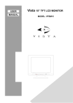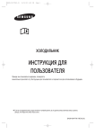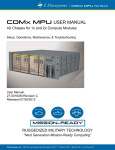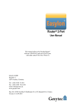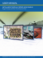
1
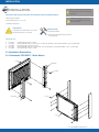
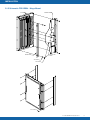
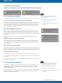
USER MANUAL
INTELLIGENT DISPLAY SERIES (IDS) PANELS
Rugged Displays with Real Time Enhanced Video
Z Microsystems, Inc.
Z Microsystems, Inc. · 9820 Summers Ridge Road, San Diego, CA 92121 · T: 858.831.7000 · F: 858.831.7001 · www.zmicro.com
REGULATORY
FCC Information
WARNING
TO PREVENT FIRE OR SHOCK HAZARDS, DO NOT EXPOSE THIS UNIT TO RAIN OR MOISTURE. ALSO, DO NOT USE THIS UNIT’S POLARIZED
AC PLUG WITH AN EXTENSION CORD RECEPTACLE OR OTHER OUTLETS UNLESS ALL THREE PRONGS CAN BE FULLY INSERTED
1. Use the power and video cables supplied
with the product to help prevent interference
with radio and television reception. The use of
cables and adapters may cause interference
with electronic equipment in the vicinity of this
unit.
2. This equipment has been designed to meet
severe conditions in military environments as
specified in MIL-STD-810G, MIL-STD-461F and
DO-160F.
3. This equipment is designed to meet the
limits for Class A digital devices imposed by Part
15 of FCC rules. These limits are designed to
provide reasonable protection against harmful
interference when equipment is operating in
commercial environments. This equipment
generates, uses and can radiate radio frequency
energy, and, if not installed and used in
accordance with the instruction manual,
may cause harmful interference to radio
communications.
CAUTION
RISK OF ELECTRIC SHOCK - DO NOT OPEN
CAUTION: TO REDUCE THE RISK OF ELECTRIC SHOCK DO NOT REMOVE
COVER (OR BACK OF UNIT). NO USER SERVICEABLE PARTS INSIDE. REFER
SERVICING TO QUALIFIED PERSONNEL.
This symbol warns the user that insulated voltage within the unit may have sufficient
magnitude to cause electric shock. Therefore, it is dangerous to make any kind of
contact with any part inside this unit.
This symbol alerts the user that important literature concerning the operation and
maintenance of this unit has been included. Therefore it should be read carefully in
order to avoid any problems.
4. Operation of this equipment in a residential
area is likely to cause interference in which
case the user will be required to correct the
interference at his own expense. Changes or
modifications not expressly approved by Z
Microsystems could void user’s authority to
operate the equipment.
IDS DISPLAYS
27-0045UM REV B Issued 02/12
2
TABLE OF CONTENTS
Table of Contents
Section
Page
1.0 Product Overview............................................................................................................................................................ 4
1.1 About This Manual.............................................................................................................................................. 4
1.2 Product Overview............................................................................................................................................... 5
2.0 Installation....................................................................................................................................................................... 6
2.1 Installation Schematics....................................................................................................................................... 6
2.1.1 Schematic for IDS 17”........................................................................................................................ 6
2.1.2 Schematic for IDS 21”........................................................................................................................ 7
2.1.3 Schematic for IDS 24”........................................................................................................................ 8
2.2 Installation Walkthrough...................................................................................................................................... 9
2.2.1 Static Mount Installation...................................................................................................................... 9
2.2.2 Hinged Mount Installation................................................................................................................... 9
3.0 Connections & Setup..................................................................................................................................................... 10
3.1 Connecting and Setting Up the IDS Display...................................................................................................... 10
3.2 Touch Panel Setup........................................................................................................................................... 11
4.0 Operations..................................................................................................................................................................... 14
4.1 Display Panel Controls...................................................................................................................................... 14
4.2 Onscreen Menus.............................................................................................................................................. 15
4.2.1 Main Menu....................................................................................................................................... 15
4.2.2 Main Screen Picture Adjust.............................................................................................................. 15
4.2.3 Main Screen Graphics Mode............................................................................................................ 15
4.2.4 Main Screen Color Balance.............................................................................................................. 15
4.2.5 Configurations Screen...................................................................................................................... 16
4.2.6 Advanced Options Screen............................................................................................................... 16
4.2.7 OSD Options................................................................................................................................... 16
4.2.8 Main Screen Information.................................................................................................................. 16
5.0 Troubleshooting............................................................................................................................................................. 17
5.1 Troubleshooting Topics..................................................................................................................................... 17
5.2 Frequently Asked Questions............................................................................................................................. 19
6.0 Customer Support......................................................................................................................................................... 20
7.0 Maintaining the IDS Display Series................................................................................................................................. 21
8.0 Replacing Parts............................................................................................................................................................. 21
9.0 Appendix....................................................................................................................................................................... 22
9.1.1 Technical Specifications for IDS 17”............................................................................................................... 22
9.1.2 Schematic Outline for IDS 17”....................................................................................................................... 23
9.2.1 Technical Specifications for IDS 21”............................................................................................................... 24
9.2.2 Schematic Outline for IDS 21”....................................................................................................................... 25
9.3.1 Technical Specifications for IDS 24”............................................................................................................... 26
9.3.2 Schematic Outline for IDS 24”....................................................................................................................... 27
27-0045UM REV B Issued 02/12
3
PRODUCT OVERVIEW
1.0 PRODUCT OVERVIEW
1.1 About This Manual
This product manual will help you through the installation and setup processes of your Intelligent
Display Series (IDS) LCD panel. We recommend you read this manual carefully and follow the
instructions in the installation chapter for verification of system functions and control settings.
This manual is also available on the Z Microsystems website at www.zmicro.com. For further
assistance please visit the Frequently Asked Questions section in the manual, or refer to the
section dedicated to Customer Support.
SAFETY PRECAUTIONS
DANGER:
To avoid shock hazard:
• Do not remove the covers around
the IDS
• Do not connect or disconnect the
IDS during an electrical storm.
For added convenience and safety, you will find embedded visual cues for quick tips, warnings,
new sections,and safety precautions. These are intended for quick supplemental reference and
added ease in the installation and operation of the IDS display.
• The power cord plug must be
connected to a properly wired and
grounded power outlet.
Notification Icons:
• Any equipment to which the IDS
will be attached must also be
connected to properly wired and
grounded power outlets.
Warnings and Caution Alerts
Notes and Preparation Information
New Section
Necessary Tools
Necessary Hardware
Necessary Software
Additional Assistance for IDS and GCS series ruggedized displays can be found on the Z Microsystem’s website along with
highly customizable integration options for a wide range of technical platforms and applications.
27-0045UM REV B Issued 02/12
4
PRODUCT OVERVIEW
1.2 Product Description
Z Microsystems Intelligent Display Series (IDS) flat panel displays are engineered with unique flexible mounting
options, an ultra-high per formance modular video processor, and touch panel options built into a rugged
lightweight protective housing. The thin, lightweight IDS panels are available in 24”, 21.3”, and 17” sizes. Each
display can be VESA arm-mounted, panel-mounted, rack-mounted, or attached to a specifically designed multidisplay mounting frame, such as the Ground Control Station (GCS series).
The IDS Displays of fer state of the ar t Real Time Enhanced Video (RTEV ) capabilities to improve tactical
sur veillance missions. These real-time image improving functions are made possible by Z microsystems third
generation video processing engine, applying image enhancements and edge detection algorithms to incoming
video streams without adding latency. The result is an unparalleled visual experience delivering mission critical
sur veillance imaging in real time without quality degradation caused by poor visibility or atmospheric inter ference.
The IDS displays also of fer an interactive touch screen functionality. Intuitive accessibility to live imager y and
intelligence translates to increased user ef fectiveness and information distribution. Together with built-in real-time
video enhancement and flexible mounting - all in rugged, lightweight packaging - make the IDS panels a wellsuited solution for a variety of fielded militar y applications.
Highlights
•
•
•
•
•
•
•
17”, 21”, & 24” active display area
Native Pixel Resolutions up to
1920 x 1200@60 pixels for 24”
1600 x 1200@60 pixels for 21”
1280 x 1024@60 pixels for 17”
Supported scaled resolutions up to
1920x1200@60 for 17”, 21”, and 24”
Digital and analog video support
RS232 Communications via USB Type B
connector
Real-time enhanced video imaging
Soft Menu user-friendly on-screen GUIs
•
•
•
•
•
•
•
•
Tough protective AR shield
Standard optically bonded AR shield
Optional optically bonded touch panel
Rugged lightweight packaging
Custom mounting options (VESA standard)
Optional quick-release mounting
Viewing angles are fully adjustable per
5th - 95th percentile MIL-STD ergonomics
specifications
Applications include shipboard,
airborne, ground vehicles, & ground control
stations
27-0045UM REV B Issued 02/12
5
INSTALLATION
2.0 INSTALLATION
NOTE: For the fastest and easiest installation of
the IDS, follow these steps in the sequence they
This section will provide information and assistance with the following topics:
• Mounting & Hardware
WARNING: Using assembly hardware that
does not match specifications may damage
• GCS Schematics for 17”, 21”, 24”
internal components.
• Installation Procedure
Preparations
In preparation to install the IDS, turn off the
electrical power to your computer.
are presented.
Required Tools
• Philips Screwdriver
• Second pair of hands for lifting and final
mounting steps
Hardware Key
•
•
•
•
•
01-92152
01-92381
01-92619
01-91872
01-91869
Flat head, Philips,10-32 x .375 IN
Washer, Stainless steel , for screw size 1/4, .281 (Inner diameter) x .625 (Outer Diameter) x .05 to .08 (thickness)
Pan head, Philips, 1/4-28 X 0.375 IN
Washer, Stainless steel, for #10 screw size, .22 (Inner diameter) x .44 (Outer Diameter) x .03 to .07 (thickness)
Pan head, Philips, 10-32 x .375 IN
2.1 Installation Schematics
2.1.1 Schematic FOR IDS17 - Static Mount
17" IDS
HINGED SIDE
4X 01-92152
HANDLE SIDE
8X 01-91869
17" IDS
27-0045UM REV B Issued 02/12
6
INSTALLATION
2.1.2 Schematic FOR IDS21 - Static Mount
21.3" IDS
4X 01-92381
4X 01-92619
HINGED SIDE
HANDLE SIDE
4X 01-91869
21.3" IDS
27-0045UM REV B Issued 02/12
7
INSTALLATION
2.1.3 Schematic FOR IDS24 - Hinge Mount
24" IDS
HINGED SIDE
4X 01-91869
HANDLE SIDE
4X 01-91872
4X 01-92381
4X 01-92619
8X 01-91869
27-0045UM REV B Issued 02/12
8
INSTALLATION
2.2 Installation Walkthrough
Installation Instructions for Static and Hinged Mounting Systems
NOTE: Refer to the schematics on the previous
pages for your respective display size for visual
affirmation and mounting rail orientation.
WARNING: Max Screw Depth 3/8”
Hardware exceeding max screw depth could
damage the display.
2.2.1 Static Mount Installation
For help with installation follow these steps and refer to the schematic for your 17”, 21”, or 24” IDS
Step 1 - Clear a safe space to work and locate hardware & mounting rails
The first step in mounting the IDS display is clearing a safe space to rest the monitor, screen side down
and collecting the parts and hardware you will need. After laying the monitor screen-down within the
the workspace prepared, locate the two mounting rails that have been provided with the IDS display
unit. These will serve as a harness for the display and the rails that will be secured directly to the mount
assembly where the monitor will rest.
Static Rail Mount Parts & Hardware
• 2 Mounting Rails
• 4 x 01-92381, 4 x 01-92382 (Washers)
• 4 x 01-92619 (Screws)
• 4 or 8 01-91689 (Depending on Monitor, refer
to schematic)
Step 2 - Attach the Mounting Rails to the IDS
NOTE: Mounting rails are equipped with guide
With the monitor, mounting rails, and hardware, position the rails so that the Guide Pins* face the
installer, and away from the IDS. With this orientation, attach the two mounting rails to the back side
of the unit using the provided hardware; or fasteners that match specifications. The nuts and screws
should be tightened finger-tight. When both of the rails are firmly secured to the IDS display, proceed to
the next step.
pins to assist with spacing and final installation of
display to mounting assembly.
* GUIDE
Test - Be sure that mounting rails are securely fastened to the display before lifting the unit.
the Mounting Rails to provide support and
Step 3 - Lift the IDS into postion and Prepare to Mount
Now that the mounting rails are securely fastened to the IDS, the monitor is prepared to be mounted
to the desired position on a mount assembly. With the aid of a second person for assistance, lift the
IDS into place. With the aid of another installer and the guide pins, guide the monitor into place on the
mounting assembly.
PIN - The Guide Pins are small
cylinder shaped metal rods that protrude from
reference guide when attaching the display to the mount.
Step 4 - Attach the Harnessed IDS to Mount
Securely attach the monitor, with mounting rails installed, to the chassis of the mount assembly using
the appropriate washers and screws as depicted in the schematic diagram. Make any necessary height
adjustments as needed and ensure that the display is securely installed and all hardware is finger-tight.
Step 5 - Proceed Connections & Setup
Be sure that the video ports and power jack on the back of the monitor have not been obstructed.
You have succesfully mounted the IDS and are now ready to setup and operate the display. Continue to
the next section.
If you have further questions regarding mounting, please refer to the troubleshooting or FAQ sections in
this manual for further assistance.
2.2.2 Hinged Mount Installation
Hinged Rail Mount Parts & Hardware
The installation for a hinged IDS mount follows the same steps as the instructions above for the static
mount installation. The major three differences are: the larger hinged mounting rail, an increased
number of fastening locations for additional support with the hinged mounting feature, and different
hardware used for attachment.
• 2 x Mounting Rails (1 Static + 1 Hinged)
The hinged mounting rail comes equipped with a sturdy hinge assembly and braided metal safety leash.
It provides the same easy installation experience as the static rails, with guide pins for installation and
convenient cable management built right in.
• 4 or 8 01-91689 (Depending on Monitor, refer
to schematic)
• 4 x 01-92381, 4 x 01-91872 (Washers)
• 4 x 01-92619, 4 x 01-92869 (Screws)
27-0045UM REV B Issued 02/12
9
CONNECTIONS & SETUP
3.0 CONNECTIONS & SETUP
This section will provide information and assistance with the following topics:
• Cable connections for power and video input
connector but will no longer support analog
signals as offered by the onboard video
• Setting up touch panel functionality with the display
• Software and Driver information for touch panel use
Preparations
In preparation to setting up and
connecting the IDS, turn off the
electrical power to your computer.
NOTE: The IDS will accept a standard DVI
processing engine.
Required Cables/Connectors
• Power Cord (Standard)
• DVI-I Cable (Supports Digital + Analog)
• USB Type B interface connector (For
Touch Screen functionality)
3.1 Connecting and Setting Up the IDS display
Step 1 - Connect the power cord to the monitor, and plug the IDS into a power outlet
Now that the IDS has been successfully installed, it is time to connect the monitor to a power source.
Once the power cable has been inserted into the IDS, connect the display to a power outlet.
Though there is no incoming video signal, the monitor now has power. In the center of the monitor
there will be a notification that reads “NO SYNC, PLEASE CHECK CABLE.” Proceed to connecting the
display to a video source.
NOTE: If the Touch Screen option has been
purchased for the IDS, ongoing communication
between the host computer and monitor is
required via USB type B (picture above).
Connector Reference
Diagrams
Video
BNC Plug
(NTSC)
BNC Jack
(NTSC)
Step 2 - Connect the IDS to video source via DVI-I cable
In addition to power, the display needs an incoming signal from a host computer. The host computer
outputs the signal and information that the user views on the display. Connect the display to the host
computer via DVI-I cable (as seen to the right in Diagram 1A).
DVI-I (Digital + Analog)
Note - A standard DVI-D cable (Diagram 1B) will broadcast a digital signal; however, it will not support
an incoming analog source. The monitor has now been supplied with power and an incoming signal.
Step 3 - (For Touch Panel Use) - This cabling step is required for Touch Panel Operation
Connect the IDS to host computer via USB Type B interface.
Operation of the touch panel functions on the IDS display requires ongoing communication with the
host computer via RS232 communications over the USB Type B connector.
Insert the male USB Type B connector (as shown in Diagram B) into the the female USB Type B receptable jack on the back of the IDS display. On the other end of the USB interface cable is a USB Type A
connector. Connect this to a Type A jack on the host computer.
Once the display has been connected to a host computer via the USB Type B connector, there will be
communication between the IDS panel and the host computer.
Standard DVI-D (Digital Only)
(Single + Dual Link)
USB Communication
USB-B Plug
USB-B Jack
USB-A Plug
USB-A Jack
Step 4 - Checking for an incoming signal
The IDS now has power and a connection to a host computer. Turn on the computer to confirm that
the display is receiving an incoming video signal. The LED channel indicator as well as the Status LED
indicator on the control panel at the bottom of the front of the display will both turn green.
If no image appears on the screen, toggle to the displays other channel.
The monitor will automatically default to digital signal. If the incoming signal is analog, please follow the
steps in the Configuration Screen subsection located in this manual’s Operations section for directions
to toggle the channel type to analog.
For additional video signal setup: repeat steps 2 and 4 for the new incoming signal.
Additional USB Type B interface communication is needed for Touch Screen Functionality. Direction and
steps for Touch Panel Setup can be found in the following section.
Setup Complete - The Z Microsystems IDS monitor is now setup and connected to a video source.
27-0045UM REV B Issued 02/12
10
CONNECTIONS & SETUP
3.2 Touch Panel Setup
Preparations
In preparation to setting up the touch panel
functionality on the IDS, turn off the electrical
power to your computer.
Required Software & Drivers
• FTDI RS232-USB Bridge Driver
NOTE: If the touch screen option has
been purchased for the IDS, the touch screen
manufacturer’s software must first be installed
on the computer being used with the IDS. Follow
Required Cables/Connectors
manufacturer’s instructions and user manual for
software installation and use.
• USB Type B interface connector
• Microchip TSHARC Touch Panel Driver
Touch Screen setup
Z Microsystems IDS Displays offer a touch screen interface option with Resistive Touch technology.
The displays utilize a Microchip ‘TSHARC’ touch screen controller chip and communicate with a host
computer using serial commands via the USB Type B physical interface. Z Microsystems electrical
architecture uses the same USB port to both upload firmware and communicate to the resistive
touch panel display.
To access the IDS touch screen functionality, the USB bridge and Microchip ‘TSHARC’ Touch Panel
drivers must both be installed on a host computer. Additionally, a USB cable must remain connected
between the host computer and the Z Microsystem’s display for ongoing communication.
Copies of the necessary drivers can be found on the Installation Disc provided with your IDS display,
as well as using the provided links in the following setup guide. A list of the latest driver versions and
links to manufacturer’s websites can also be found at Z Microsystem’s website.
http://www.zmicro.com/downloads/drivers.html
Setup Process for Touch Panel
Complete Cabling Step 3 in Connections & Setup and then Proceed.
Step 1 - Download and Install RS232 over USB drivers
Z Microsystem’s touch panel driver communicates to a host computer via a RS232 over USB bridge. In
order to communicate with the touch panel, you must first install the FTDI RS232-USB bridge driver from
the following link:
http://www.ftdichip.com/Drivers/VCP.htm
OR
http://www.zmicro.com/downloads/drivers.html
An Installation guide and additional drivers for various operating systems are also available from the FTDI
website.
Once installed, the driver will assign two Virtual Communication Ports (VCP) when the display is connected
to the host computer via the USB Type B cable. The first Virtual Comm. Port is for serial communication to
the display controller. The second VCP is assigned to the touch panel control.
WINDOWS USERS: For ease and compatability
most Microsoft Windows users, including Windows
7 users should select the Setup.exe labelled as a
Win7/Vista/WinXP driver. (It is distinguished in the
‘Notes’ column as a ‘Third party Driver’).
Step 2 - Download and Install Microchip TSHARC Touch Panel driver
Once the RS232 over USB drivers are installed from Step 1 above, procee to download the touch panel
drivers from the following link:
http://www.microchip.com/stellent/idcplg?IdcService=SS_GET_PAGE&nodeId=2830
Select the appropriate driver for your operating system from the table provided. (i.e. Windows, Linux, Mac)
27-0045UM REV B Issued 02/12
11
CONNECTIONS & SETUP
Setup Process for Touch Panel (Continued)
Step 3 - Install and Setting the TSHARC Touch Panel Driver COM port
Select Microchip, TSHARC-X/X, Serial Option and the respective Port COM setting. Once complete, Click
on the Install button.
Upon successful installation of driver, reboot computer if necessary. If the touch panel is not responding, open the ‘Universal Pointer Device Driver (UPDD)’ Control Panel and update the COM port setting.
Indicate which Port number your touch panel is connected to and test again.
NOTE: If the Touch Panel is not responding,
open the ‘Universal Pointer Device Driver
(UPDD)’ Control Panel and update the COM
port setting.
Step 4 - Configuring the TSHARC Touch Panel driver
For basic Touch Panel operation, proceed to the ‘Universal Pointer Device Driver (UPDD)’ Control Panel.
The UPDD control panel allows the user to set calibration and other touch panel device properties. Complete the following steps for key setup and calibration requirements:
To use the Touch Panel with Click and Drag settings - Select “Click Mode” tab from the menu on the left,
then verify the hardware is configured to Click and Drag in the pull down menu.
NOTE: If Touch Panel is not responding
Step 5 - Calibration of the Touch Screen Controller
accurately, in addition to the Microchip Touch
Select the “Calibrate” tab and follow the on-screen guide to ensure the touch screen controller is properly
calibrated for your display. Calibration window is illustrated below.
Panel may need to be calibrated through the
Screen Controller calibration, the Touch
calibration resource in your operating system.
27-0045UM REV B Issued 02/12
12
CONNECTIONS & SETUP
Setup Process for Touch Panel (Continued)
User may also need to calibrate the touch screen panel using the calibration resource specific to their
respective operating system (i.e. Windows, Linux, Mac)
Continuous Touch Panel Sensing Option
Some users may require continuous touch panel sensing. The Default settings for the UPDD driver are
set to use lift-off packets that prevent sustained press and sensing. If the desired functionality of the
touch panels requires continuous sensing of touch, proceed to ‘disable’ life-off packet by un-checking
the lift-off packet option, or by adjusting the lift-off time to a value of ‘0’ as shown below.
Congratulations your Z Microsystems IDS display is now connected, calibrated, and ready for Touch
Panel operations!
Additional Setup Assistance
For further assistance with touch screen functionality, connectivity, calibration, or other technical issues
please refer to the Troubleshooting and FAQ sections located in this manual. Z Microsystems customer
service can also be reached at +1 (858) 831-7040 or via email at [email protected].
Additional Product Support
For additional information on the IDS platform or the Ground Control Station (GCS) Display Series
featuring customizable quick release locking features for rapid panel replacement and fast transport
features, visit the Z Microsystems website at www.zmicro.com, or contact your Z Microsystems sales
representative.
27-0045UM REV B Issued 02/12
13
OPERATIONS
4.0 Operations
This section will provide information and assistance with the following topics:
• Front Display Controls
• Navigating the On-Screen Menus
• Menu Configuration and Settings
4.1 Front Display Controls
Push Button Controls
The IDS features push-button controls on the lower front bezel of the monitor casing. These buttons
provide easy access to the On-Screen Display (OSD) allowing the user to navigate and adjust image
settings.
To setup the display, use the following controls to fine tune the image on the screen:
Green LED
(Channel 1)
Input Select
Green LED
(Channel 2)
+
Menu/Select
Status
(Red/Green/Amber)
Exit
Standby
-
Button Functionality Description Table:
Display Key
Input Select
Menu/Select
-
+
Exit
Standby
Key Function
Toggles between
available channels
with active incoming
signal. corresponds
with illuminated
Channel LEDs on the
IDS display.
Activates On-Screen
Display. Activates/
Deactivates Selected
Menu Item. (Changes
are saved as they are
modified)
Moves to previous
menu item.
Decreases value of
the Selected Menu
Item.
Moves to next menu
item. Increases value
of the activated menu
item.
Exits from On-Screen
Display main menu
or returns from
submenu to main
menu. (Changes are
saved as they are
modified)
Hold down to turn
the backlight on and
off. (Power Saving
Option)
Channels LEDs
Status LED
1 — Green — Input video #1 selected (DVI-I)
Green — power and signal
2 — Green — Input video #2 selected (DVI-I)
Amber — power and no signal
Red - alarm
Off — Standby mode / no power.
27-0045UM REV B Issued 02/12
14
OPERATIONS
4.2 On-Screen Menus
NOTE: The control buttons allow the user to
4.2.1 Main Menu
control backlight operations; to store settings,
and to revert to factory-saved settings.
MAIN MENU
R. 52
To access the On-Screen Display main menu, press the menu button on the front of the panel. All
IDS functions are controlled using the Main Menu’s subtopics.
PICTURE ADJUST
GRAPHIC MODE
These submenus can be accessed for adjustments and information via the display keys on the
bottom panel of the display. See the sections below for specifics and operation of the submenus.
COLOR BAL ANCE
CONFIGURATION
INFORMATION
ADVANCED OPTIONS
4.2.2 Main Screen Picture Adjust
PICTURE ADJUST
MAIN
CH 1
MAIN BRIGHTNESS
MAIN CONTRAST
0
100
0
100
To adjust the display brightness and contrast use the + and - buttons to highlight the “Picture Adjust”
option. Press the “Menu” button to access the submenu.
Navigate to the desired option using the + and - buttons. Use the Menu button to activate the option.
(Background color of the slider will change when the option is selected.) Use the + and - buttons to
increase or decrease the value. Press Menu button again to deactivate the option. This will save any
changes.
(NOTE: Contrast is not available for digital signal images and “Main Contrast” option will be grayed
out and unavailable.)
4.2.3 Main Screen Graphics Mode
To make adjustments to the display images positioning, width, or the video sampling clock use the + and - buttons to highlight the “Graphics Mode”
submenu. Press the “Menu” button to access the “Graphics Mode” submenu.
GRAPHICS MODE
MAIN
CH 1
HORIZ. COARSE
HORIZ. FINE
VERT. POSITION
HORIZ. POSITION
0
100
0
100
0
100
0
100
The “Graphics Mode” menu is used to adjust the positioning of the image. Highlight the desired
option using the + and - button. Use the Menu button to activate the option. (Background color of the
slider will change.) Use the + and - buttons to increase or decrease the value of the selected option.
Adjust the image to desired specifications and press menu again when finished to deactivate the
option.
The “Horz Coarse” option adjusts the horizontal width of the image.
The “Horz Fine” option adjusts the phase of the video sampling clock.
Press “Exit” to return to the Main Menu. The new adjustments will be applied automatically.
4.2.4 Main Screen Color Balance
(NOTE: The Horz Coarse and Horz Fine options are not applicable for digital channels).
To adjust the color of the display use the + and - buttons to highlight the “Color Balance” submenu. Press the “Menu” button to access the
“Color Balance” submenu.
COLOR BALANCE
MAIN
Highlight the color balance submenu using the + and - buttons. Use the Menu button to activate the
desired option. (Background color of the slider will change.) Use the + and - buttons to increase or
decrease the value. Press menu again to deactivate the option.
CH 1
RED
GREEN
BLUE
0
100
0
100
0
100
Press “Exit” to return to the Main Menu. The new adjustments will be applied
automatically.
(NOTE: Color Balance menu topics Red, Green, and Blue adjustments are available only for analog
signal images. Menu topics will be unavailable and grayed out for digital signals)
27-0045UM REV B Issued 02/12
15
OPERATIONS
4.2.5 Configuration Screen
CONFIGURATION
MAIN
MENU TIMEOUT
0
100
fACTORY SETTINGS
CHANNEL 1 T YPE:
ANALOG
CHANNEL 2 T YPE:
ANALOG
CHANNEL SELECT:
CHANNEL 2
SCALE MODE:
NORMAL
Menu Timeout:
This is the amount of time the menu will remain displayed before it times out and exits automatically.
When the menu times out, it disappears from the main screen.
Reset Default Settings:
Resets all Main Menu settings to the factory default settings.
Channel Type:
Channel Type sets the DVI-I Channel to accept either analog or digital input.
Channel Select:
The IDS Display has two channel options. Highlight “Channel Select” and press Menu button to
change channels.
Scale Mode:
There are three scale modes: NORMAL, SCALED ASPECT RATIO (SAR), and NO SCALE. NORMAL mode scales the source image to the full panel size and
aspect ratio. SAR mode will keep the aspect ratio of the incoming signal and use the maximum image size possible for the source aspect ratio. NO SCALE
mode uses the native source resolution and aspect ratio and displays the image without scaling. SAR and NO SCALE images are centered on the
panel with black bars on the sides where no image is present.
4.2.6 Advanced Options Screen
ADVANCED OPTIONS
These options are for future development of Z Micro proprietary video processing engine technology.
MAIN
RTEV Settings:
Not available at this time. Please contact your Z Micro Sales Rep for more information.
RTEV SETTINGS
RTEV GEOMETRY
RTEV Geometry:
Not available at this time.Please contact your Z Micro Sales Rep for more information.
OSD OPTIONS
4.2.7 OSD OPTIONS
OSD Options allows you to modify OSD menu settings to adjust position and transparency of the
easy access On-Screen Display.
OSD OPTIONS
MAIN
VERT POSITION
HORIZ POSITION
OSD TRANSPARENCY:
0
100
0
100
Vert Position:
Vert Position allows the user to change the position of the OSD screen in vertical position.
Horiz Position:
Horiz Position allows the user to change the position of the OSD screen in horizontal position.
DISABLE
OSD Transparency:
OSD Transparency allows the user to change the transparency of the OSD screen.
4.2.8 Main Screen Information
Use the + and - buttons to highlight the “Information” option. Press the “Menu” button to access the
“Information” submenu.
Within this submenu, the user can view firmware version, build date, incoming video signals, and
display operating temperature.
Temperature displayed is the onboard circuit-board temperature. Temperature variation is common
and expected.
WARNING: It is advised to contact Z
Microsystems customer support if the
temperature exceeds 65C.
27-0045UM REV B Issued 02/12
16
TROUBLESHOOTING
5.0 TROUBLESHOOTING THE IDS SERIES
5.1 Troubleshooting Topics
This section will provide information and assistance with the following topics:
• Troubleshooting Topics for the IDS Series
• Frequently Asked Questions about the IDS Series
No Main Display Image
If the cable from the computer to the display is secure, determine the color of the standby LED and follow the appropriate procedure below.
Black - Cause: If the status LED is black (unlit), the unit is on standby or is not receiving power.
Recovery:
• Press and hold standby button.
• Ensure the power cable is plugged into the source.
• Connect the power cable to a AC outlet. Ensure the AC outlet is active.
• Turn on the display’s backlight by pressing the standby button.
Amber - Cause: If the status LED is amber, there is power but no video signal is being received.
Recovery:
•If Video 1 or Video 2 is selected, ensure there is a video signal coming into the selected channel.
•Ensure there is a video signal coming from the computer.
•Be sure the channel type is set correctly for the video signal that is provided by the graphics card. Confirm that the display is setup to analog or digital
and verify the outgoing signal from the host computer matches this signal type.
Green - Cause: When the status LED is green, there is both power and a video signal. If there is still no image, follow these recovery steps:
Recovery:
• Ensure the video signal coming from the computer is not a black screen.
• Ensure the Channel Type is selected corresponding to the incoming video signal.
• Ensure the Channel Type under “Configuration” in the OSD menu corresponds to the signal type (i.e. ANALOG or DIGITAL).
• Make sure the right cable is being used for the incoming video signal. DVI-D will not support an ANALOG signal.
• Try a known supported video source resolution and frequency as listed in the Appendix for specifications.
• If these Recovery criteria have been met and the issue is not resolved there is potentially a hardware failure. (Tech Support pg. 20)
Display Image has Poor Color or Brightness (Analog Signal Issue)
Possibe Recovery:
Red, Green, and Blue gains can be adjusted from the Color Balance menu topic within the OSD Main Menu. Best quality color is generally achieved when
red, green, and blue gains are balanced and all at similar levels. In the Picture Adjust submenu, ensure “Main Brightness” setting is at a sufficient level.
Display Image Has Vertical Bars (Analog Signal Issue)
Possibe Recovery:
If the main image begins to display vertical bars, adjust the “Horz Coarse”. From the Main Menu, use the ‘+’ and ‘-’ buttons to highlight the “Graphics
Mode” option. Select the “Graphics Mode” submenu and use the left and right arrow buttons to adjust the screen until the number of bars is reduced.
Continue adjusting one step at a time until the bars are no longer visible.
Make sure that the connectors are seated properly on the back of the display. “Horz Coarse” option is only available for Analog video signals.
Display Image Has Horizontal Bars (Analog Signal Issue)
Possible Recovery:
If the main image begins to display horizontal bars, check that the video input cable is securely attached to the back of the monitor. If this does not resolve
the issue there is a chance the connector cable is damaged or defective. Try replacing the DVI cable with a new one to see if the bars disappear.
27-0045UM REV B Issued 02/12
17
TROUBLESHOOTING
Display Image Appears Fuzzy / Poor Quality (Analog Signal Issue)
Possible Recovery:
If the main image begins to appear fuzzy or “noisy”, adjust the “Horz Fine” until it is reduced. The “Horz Fine” option adjusts the phase of the
video sampling clock. To access the “Horz Fine” submenu from the Main Menu, use the ‘+’ and ‘-’ arrow buttons to highlight the “Graphics Mode”
option. Press the “Menu” button to access the “Graphics Mode” submenu. The “Horz Fine” and “Horz Coarse” options are only availabe to ANALOG
video sources.
If the configuration screen reads ANALOG for the Channel Type and the user is expecting a DIGITAL signal, then the display may not be
receiving a digital signal that it can understand. This problem may result from an incompatibility in the graphics card. The source graphics
card may not be certified to full DVI-I specification and may be defaulting to an analog signal. One option is to change the configuration in the
graphics card to transmit only a DVI-D signal. A second option is to use a DVI-D cable to connect the host system to the display.
Possible Recovery:
In some cases, poor image quality may be caused by a break in the connection. Check for potential breaks by looking for damage or frays to the
cable, particularly near connector heads. Also check connector pins to ensure that they are properly aligned to fit into the designated connector
jack. If the problem persists, try replacing the video cable.
Possible Recovery:
Some electronics and cellular devices generate electrical/radio interference. The problem may result from close proximity to such a device. Be
sure that all items that may cause interference are kept away from the display.
Possible Recovery:
Low signal level is a potential cause for poor image quality. If the previous processes have not resolved the issue, try connecting the display to a
video source that provides a clear picture to another display. This will rule out variables and narrow troubleshooting direction.
Possible Recovery:
Make sure that video cables are properly seated on the back of the display panel. A bad seating can have the RGB connectors misaligned. These
RGB options are only available for Analog video signals. In the event that these color adjustments have been changed and are out of balance Reset menu settings to default.
Display Image is Not Centered
If the main image is not centered on the display, access the “Graphics Mode” menu in the OSD. Using the ‘+’ and ‘-’ buttons adjust the ‘Vert’ and
‘Horz’ position until image is appropriately centered.
If the OSD is not positioned in a desired location, an independent menu for OSD options can be found within the “Advanced Options” menu.
Problems with Analog Signal Resolution at 1920x1200@60
Possible Recovery:
This issue is generally resolved by designating the correct signal format (digital or analog) under Channel Type in the Configurations OSD menu.
This communicates to the display the correct Extended Display Identification Data (EDID) information. The settings are passed on to the Graphics
Card and 1920x1200@60 reduced blankoing is produced by the graphics card.
Be sure that the EDID information is passed to the graphics card and that your graphics card recognizes the IDS Display as a “ZMicro display.”
27-0045UM REV B Issued 02/12
18
FREQUENTLY ASKED QUESTIONS
Touch Screen Not Responding Accurately
The Touch Screen may require calibration from time to time. There are two forms of calibration, one is the touch panel controller in the UPDD control
panel as discussed in the Touch Panel Setup installation guide. Another method is direct contact with the display through a utility built into the operating
system on your host computer.
Other Touch Screen Aesthetics
Image appears Fuzzy
In the event that the image appears fuzzy, this may be a by-product of the resistive touch screen technology. With the resistive touch screen over the LCD
display there is a reduction in transmissivity of the LCD of 80%. This is normal and once again is a by-product of the resistive touch technology.
Touch Screen Anomalous Rippling
As an industry standard: resistive touch screen technology has produced a standard cosmetic issue referred to as “rippling.” Rippling is due to the
non-uniform expansion rate of of the lower layers of glass that make up the resistive touch screen assembly. This issue is inherent to resistive touch
technology and is a known issue.
NOTE: The functionality of the unit is not impacted by this rippling and in most cases can only be detected when the display’s backlight has been turned
off.
5.2 Frequently Asked Questions
Question:
Answer:
• Why are certain Menu Options blocked out and unavailable?
• Certain Menu Options are specific to DIGITAL or ANALOG signals.
• What is the purpose of the metal surrounding one of the screw
threadings on the back side of the monitor?
• This surrounding metal area is for the purpose of grounding the display.
• How do I update my displays’s firmware?
• Updating the firmware for a display can be sensitive. Before starting this
process, please review the specific configuration for your display series.
Also, updating your firmware will depend on your display’s interface.
Does your display offer hyperterminal support?
Does your display use traditional RS-232 serial communications or USB?
27-0045UM REV B Issued 02/12
19
CUSTOMER SUPPORT
6.0 CUSTOMER SUPPORT
NOTE: For image problems, run AUTO SETUP
NOTE: If possible, stay by the computer.
NOTE: More help, late-breaking news, and
again before consulting this section. In most
The Z Microsystems Technical Support
details of the latest accesories for these
cases, AUTO SETUP can fix the problem. See
Representative may wish to go through the
products may be found on the worldwide web at
Auto Setup section for details
problem over the telephone.
www.zmicro.com
Technical Support
If you are unable to correct the problem yourself, contact Z Microsystems at:
Phone: Fax:
Website:
Email: (858) 831-7040
(858) 831-7001
www.zmicro.com
[email protected]
Before calling, please have available as much of the following informationa s possible:
1. Model and serial number for the label on the monitor.
2. Purchase P.O.
3. Description of the problem
4. Computer type and model
5. System configuration (hardware fitted, etc.)
6. System BIOS version number
7. Operating System and version number
8. Display driver version number
9. Video Adapter Type
Documentation Assistance
If you are unable to find documentation for a specific product or would like to request further information, contact Z Microsystems at:
Phone:
Email: (858) 831-7039
[email protected]
Customer Feedback
We value feedback on our products, their performance, problems found, and welcome all suggestions.
Please send to:
Customer Service
Z Microsystems
9820 Summers Ridge Road
San Diego, CA 92121
or www.zmicro.com
27-0045UM REV B Issued 02/12
20
MAINTENANCE & REPLACEMENT
7.0 MAINTAINING THE IDS DISPLAY SERIES
Cleaning the Monitor
Unplug the monitor from the power outlet before cleaning.
• The IDS Displays are constructed with either an optically bonded resistive
touch screen or optically bonded Anti Reflective (AR) shield. When cleaning the screen surface, a
clean, lint-free cloth must be used. Isopropyl alcohol or monitor glass cleaner may be used to clean
finger prints or smudges on the monitor’s screen. First, apply the cleaning solution to the clean,
lint-free cloth before wiping the monitor. Do not apply the cleaning solution directly to
the monitor.
WARNING: Do not spray water or cleaning
CAUTION: Do not use benzene, thinner,
solution directly on the display. Apply first to a
ammonia or any volatile substance to clean
lint-free cloth before wiping the monitor.
the monitor screen or housing. These
WARNING
Be sure to turn off the power before
you perform any maintenance on
the monitor.
WARNING
To avoid risk of electric shock, do
not disassemble the monitor cabinet.
Users cannot service the monitor. User
maintenance is restricted to cleaning
as explained below.
chemicals may damage the monitor.
WARNING: Do not use water to clean the LCD
screen.
8.0 REPLACING PARTS
If the Z Microsystems Technical Support Engineer determines that the product needs to be replaced, a Customer Service Representative will issue a
Return Material Authorization (RMA) number.
An RMA number is required to return a product to Z Microsystems, regardless of the reason for the return.
The Z Microsystems Customer Service Department/RMA Request Form will ask the customer to provide the following information:
• model number of the defective product
• serial number of the defective product
• firmware revision (as detailed in the “Information” section of the Main Menu
• problem with the defective product
• return “ship to” address
• the name and address of the company department to which we will send the invoice (if product is out of warranty or is different from the “ship to”
address.
• phone number and e-mail address of contact
• purchase order number
You will be given an RMA number and will be asked to send the product to:
Z Microsystems
ATTN.: (RMA#) It is very important to reference the RMA#
9820 Summers Ridge Road
San Diego, CA 92121
27-0045UM REV B Issued 02/12
21
APPENDIX
9.0 APPENDIX
This section will provide information and assistance with the following topics:
• Technical and Operational Standards for the IDS displays
• Technical Schematics for the IDS displays
• Engineering Drawings for the IDS displays
9.1.1 TECHNICAL SPECIFICATIONS FOR IDS 17”
The IDS Display series is meticulously engineered to be adaptable and suited for an array of field operation, as well as being designed to support a
wide selection of resolutions. The specifications unique to each particular LCD can vary. These particular specifications are available through our sales
department.
Environmental
LCD Panel
17"
Operating Temp
0°C to +50°C
Native Pixels
1280 x 1024 (1.3 Million Pixels)
Extended Op Temp**
-20ºC to +50ºC
Color Paletter
16.7 Million
Non-Op Temp
-40ºC to +70ºC
Viewing Angle
+/-85º Horizontal / +/- 80º Vertical
Humidity
5% to 95% Non condensing (Design Goal)
Controls
User accessible via Control Panel or SoftMenu
Non-Op Altitude
Up to 40,000 ft.
Options
TouchScreen, AR Shield, AG Shield
Operating Altitude
Up to 15,000 ft.
Wire Mesh*
Vibration
MIL-STD-167
Shock
MIL- STD 810F, 30g’s
Fungus
Non-Nutrients/Contaminants
Active Display Size
Power
Power Consumption
44W
Power Supply
100-240 VAC, 2.0A input @ 50-60Hz, 400Hz
Input Connectors
Reliability
MTBF
50,000 hrs, Backlight and LCD only
MRRT
<30 Minutes
Display
DVI-I with optional features including analog
(HD-15), NTSC/PAL (BNC), digital (DVI-I), or
HDSDI (BNC)
Power Cable
6' cable, 1x IEC C14 Inlet Connector Standard
Safety
UL60950
MIL-STD-461E, RE101 Army Limits, RE102,
Touch Screen Interface
6' 9-pin DSUB provided (pins 2, 3, 5, straight
through) 10' cable, DB9
EMI/EMC
RS101, RS103 (20v/m 2MHz and 60v/m 1GHz18GHz), CE101, CS114, CS115, CS116
Physical
Regulatory
Quality/Workmanship
Size
12.02” H x 14.6” W x 2.17” D
Weight
10.6 lbs.
IPC / ISO 9001:2008 and applicable section of MIL-HDBK-454
Supported Resolutions
1920x1080x60Hz, 1920x1200x60Hz, 1440x900x60Hz, 1280x1024x60Hz,
1280x1024x67Hz, 1280x1024x75Hz, 1280x1024x85Hz, 1280x768x60Hz,
1280x768x75Hz, 1152x864x75Hz, 800x600x60Hz, 800x600x72Hz,
800x600x75Hz, 800x600x85Hz, 640x480x75Hz, 640x480x85Hz
27-0045UM REV B Issued 02/12
22
APPENDIX
9.1.2 SCHEMATIC OUTLINE FOR IDS 17”
4
3
2
1
REVISIONS
REV
DESCRIPTION
DATE
PREP
APVD
01
ENGINEERING PROTOTYPE
--
--
--
12.02
D
.25
14.68
.97
.80
4X 10-32
1.01
13.08
.145
4X 10-32
MODEL/SERIAL
LABEL
.264
C
8.35
9.686
3.937
4.040
2.86
1.165
8
7
5.370
3.937
6
5
B
1.01
.400
13.877
2.22
USB HOST
DVI-I 1
UNLESS OTHERWISE SPECIFIED
DIMENSIONS ARE IN INCHES
TOLERANCES ARE:
DECIMALS
FRACTIONS
XX = .01
1/32
XXX = .005
ANGLES
1
63
THIS DOCUMENT IS THE PROPERTY OF
Z MICROSYSTEMS, INC. AND CONTAINS
INFORMATION WHICH IS PROPRIETARY TO
Z MICROSYSTEMS, INC. NO PART OF THIS
DOCUMENT MAY BE COPIED, REPRODUCED
OR DISCLOSED TO THIRD PARTIES
WITHOUT PRIOR WRITTEN CONSENT OF
Z MICROSYSTEMS, INC.
INTERPRET DIMENSIONS & TOLERANCES
PER ASME Y14.5M-1994
DATE
NAME
DVI-I 2
A/C POWER
Z Microsystems, Inc.
9830 Summers Ridge Rd, San Diego, CA 92121
Phone: (858) 831-7000 Fax:(858) 831-7001
TITLE
27-0045UM REV B Issued 02/12
DSPL,DUAL DVI-I,17IN,IDS
A
23
APPENDIX
9.2.1 TECHNICAL SPECIFICATIONS FOR IDS 21”
The IDS Display series is meticulously engineered to be adaptable and suited for an array of field operation, as well as being designed to support a
wide selection of resolutions. The specifications unique to each particular LCD can vary. These particular specifications are available through our sales
department.
Environmental
LCD Panel
21.3"
Operating Temp
0°C to +50°C
Native Pixels
1600 x 1200 (2 Million Pixels)
Extended Op Temp**
-20ºC to +50ºC
Color Paletter
16.7 Million
Non-Op Temp
-40ºC to +70ºC
Viewing Angle
Full +/-85º
Humidity
5% to 95% Non condensing (Design Goal)
Controls
User accessible via Control Panel or SoftMenu
Non-Op Altitude
Up to 40,000 ft.
TouchScreen, AR Shield, AG Shield
Operating Altitude
Up to 15,000 ft.
Wire Mesh*
Vibration
MIL-STD-167
Shock
MIL- STD 810F, 30g’s
Fungus
Non-Nutrients/Contaminants
Active Display Size
Options
Power
Power Consumption
66W
Power Supply
100-240 VAC, 2.0A input @ 50-60Hz, 400Hz
Input Connectors
Reliability
MTBF
50,000 hrs, Backlight and LCD only
MRRT
<30 Minutes
Display
DVI-I with optional features including analog
(HD-15), NTSC/PAL (BNC), digital (DVI-I), or
HDSDI (BNC)
Power Cable
6' cable, 1x IEC C14 Inlet Connector Standard
Safety
UL60950
MIL-STD-461E, RE101 Army Limits, RE102,
Touch Screen Interface
6' 9-pin DSUB provided (pins 2, 3, 5, straight
through) 10' cable, DB9
EMI/EMC
RS101, RS103 (20v/m 2MHz and 60v/m 1GHz18GHz), CE101, CS114, CS115, CS116
Physical
Regulatory
Quality/Workmanship
Size
14.2” H x 18.45” W x 2.29” D
Weight
18 lbs.
IPC / ISO 9001:2008 and applicable section of MIL-HDBK-454
Supported Resolutions**
1920x1080x60Hz, 1920x1200x60Hz, 1440x900x60Hz, 1280x1024x60Hz,
1280x1024x67Hz, 1280x1024x75Hz, 1280x1024x85Hz, 1280x768x60Hz,
1280x768x75Hz, 1152x864x75Hz, 800x600x60Hz, 800x600x72Hz,
800x600x75Hz, 800x600x85Hz, 640x480x75Hz, 640x480x85Hz
27-0045UM REV B Issued 02/12
24
APPENDIX
9.2.2 SCHEMATIC OUTLINE FOR IDS 21”
4X 1/4-2
MODEL/SE
LABEL
C
4
3
2
1
REVISIONS
14.20
REV
DESCRIPTION
DATE
PREP
APVD
01
ENGINEERING PROTOTYPE
--
--
--
D
B
.
.25
18.45
4X 1/4-28
.232
.80
1.26
16.85
4X 10-32
1.03
.296
MODEL/SERIAL
LABEL
C
10.24
A
13.29
3.937
8
7
6
5
5.132
4
3.96
B
.46
7.258
1.03
.457
3.937
17.54
2.53
USB HOST
UNLESS OTHERWISE SPECIFIED
DIMENSIONS ARE IN INCHES
TOLERANCES ARE:
DECIMALS
FRACTIONS
DVI-I 1
THIS DOCUMENT IS THE PROPERTY OF
Z MICROSYSTEMS, INC. AND CONTAINS
INFORMATION WHICH IS PROPRIETARY TO
Z MICROSYSTEMS, INC. NO PART OF THIS
DOCUMENT MAY BE COPIED, REPRODUCED
DVI-I 2
A/C POWER
27-0045UM REV B Issued 02/12
Z Microsystems, Inc.
9830 Summers Ridge Rd, San Diego, CA 92121
Phone: (858) 831-7000 Fax:(858) 831-7001
25
A
APPENDIX
9.3.1 TECHNICAL SPECIFICATIONS FOR IDS 24”
The IDS Display series is meticulously engineered to be adaptable and suited for an array of field operation, as well as being designed to support a
wide selection of resolutions. The specifications unique to each particular LCD can vary. These particular specifications are available through our sales
department.
Environmental
LCD Panel
Active Display Size
24"
Operating Temp
0°C to +50°C
Native Pixels
1920 x 1200 (2.3 Million Pixels)
Extended Op Temp**
-20ºC to +50ºC
Color Paletter
16.7 Million
Non-Op Temp
-40ºC to +70ºC
Viewing Angle
Full +/-89º
Humidity
5% to 95% Non condensing (Design Goal)
Controls
User accessible via Control Panel or SoftMenu
Non-Op Altitude
Up to 40,000 ft.
Options
TouchScreen, AR Shield, AG Shield,
Operating Altitude
Up to 15,000 ft.
Wire Mesh*
Vibration
MIL-STD-167
Shock
MIL- STD 810F, 30g’s
Fungus
Non-Nutrients/Contaminants
Power
Power Consumption
101W
Power Supply
100-240 VAC, 2.0A input @ 50-60Hz, 400Hz
Input Connectors
Reliability
MTBF
50,000 hrs, Backlight and LCD only
MRRT
<30 Minutes
Display
DVI-I with optional features including analog
(HD-15), NTSC/PAL (BNC), digital (DVI-I), or
HDSDI (BNC)
Power Cable
6' cable, 1x IEC C14 Inlet Connector Standard
Safety
UL60950
MIL-STD-461E, RE101 Army Limits, RE102,
Touch Screen Interface
6' 9-pin DSUB provided (pins 2, 3, 5, straight
through) 10' cable, DB9
EMI/EMC
RS101, RS103 (20v/m 2MHz and 60v/m 1GHz18GHz), CE101, CS114, CS115, CS116
Physical
Regulatory
Quality/Workmanship
Size
14.36” H x 22.01” W x 2.79” D
Weight
18.7 lbs.
IPC / ISO 9001:2008 and applicable section of MIL-HDBK-454
Supported Resolutions
1920x1080x60Hz, 1920x1200x60Hz, 1440x900x60Hz, 1280x1024x60Hz,
1280x1024x67Hz, 1280x1024x75Hz, 1280x1024x85Hz, 1280x768x60Hz,
1280x768x75Hz, 1152x864x75Hz, 800x600x60Hz, 800x600x72Hz,
800x600x75Hz, 800x600x85Hz, 640x480x75Hz, 640x480x85Hz
27-0045UM REV B Issued 02/12
26
APPENDIX
D
9.3.2 SCHEMATIC OUTLINE FOR IDS 24”
4X 1/4-28
.232
.80
MODEL/SERIAL
LABEL
C
14.36
4
3
2
13.444 3.937
1
REVISIONS
4
REV
DESCRIPTION
DATE
PREP
APVD
01
ENGINEERING PROTOTYPE
--
--
--
3
2
1
REVISIONS
REV
DESCRIPTION
DATE
PREP
APVD
01
ENGINEERING PROTOTYPE
--
--
--
4X 10-32
.25
4X 1/4-28
.232
.80
20.41
22.01
1.03
D
.457
.457
4X 10-32
.232
4X 1/4-28
.296
1.76
MODEL/SERIAL
LABEL
B
5.211
D
.80
.296
20.41
MODEL/SERIAL
LABEL
9.32
3.03
C
13.444 3.937
9.32
C
13.444 3.937
A
5.211
5.211
.457
1.03
4.04
8
7
9.037
3.937
.457
AIR INLET
6
5
4.04
21.097
4
B
.457
AIR INLET
1.03
9.037
3.937
.457
21.097
B
3.03
USB HOST
DVI-I 1
DVI-I 2
A/C POWER
3.03
UNLESS OTHERWISE SPECIFIED
DIMENSIONS ARE IN INCHES
TOLERANCES ARE:
DECIMALS
FRACTIONS
XX = .01
1/32
XXX = .005
USB HOST
ANGLES
1
63
DO NOT SCALE DRAWING
MATERIAL:
N/A
Z Microsystems, Inc.
THIS DOCUMENT IS THE PROPERTY OF
Z MICROSYSTEMS, INC. AND CONTAINS
INFORMATION WHICH IS PROPRIETARY TO
Z MICROSYSTEMS, INC. NO PART OF THIS
DOCUMENT MAY BE COPIED, REPRODUCED
OR DISCLOSED TO THIRD PARTIES
WITHOUT PRIOR WRITTEN CONSENT OF
Z MICROSYSTEMS, INC.
INTERPRET DIMENSIONS & TOLERANCES
PER ASME Y14.5M-1994
DATE
NAME
DVI-ITITLE
1
DRAWN
T. CRANDELL
DVI-I 2
D
A/C POWER
DSPL,DUAL DVI-I,24IN,IDS
27-0045UM REV B Issued 02/12
1/28/10
THIS DOCUMENT IS THE PROPERTY OF
UNLESS OTHERWISE SPECIFIED
Z MICROSYSTEMS, INC. AND CONTAINS SIZE
DIMENSIONS ARE IN INCHES CHECKED
INFORMATION WHICH IS PROPRIETARY TO
TOLERANCES ARE:
Z MICROSYSTEMS, INC. NO PART OF THIS
N/A
DOCUMENT MAY BE COPIED, REPRODUCED
DECIMALS
FRACTIONS
DISCLOSED
TO THIRD PARTIES
1/28/10
APPROVEDOR M.
HUNTRESS
XX = .01
1/32
FINISH:
A
9830 Summers Ridge Rd, San Diego, CA 92121
Phone: (858) 831-7000 Fax:(858) 831-7001
FSCM
Z Microsystems,
Inc.
03-30043
DWG NO.
0XWT1 9830 Summers Ridge Rd, San Diego, CA 92121
Phone: (858) 831-7000 Fax:(858) 831-7001
REV
01
A
27
Z Microsystems, Inc.
9820 Summers Ridge Road
San Diego, CA 92121
Phone: (858) 831-7000
Fax: (858) 831-7001
Website: www.zmicro.com
Copyright 2012 Z Microsystems, Inc. All Rights Reserved
Z Microsystems, Inc.
Z Microsystems, Inc. · 9820 Summers Ridge Road, San Diego, CA 92121 · T: 858.831.7000 · F: 858.831.7001 · www.zmicro.com