1
605Di-gb/3
605Di
605Di/R
PB 0244
Issue 1
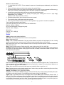
Drive/s:
EPROM:
Pumphead/s:
605Di
Issue 1
2.02
Issue 1
2
Declarations
Declaration of
conformity
When this pump unit is used as a stand alone pump it complies with: Machinery Directive
89/392/EEC EN60204-1, Low Voltage Directive 73/23/EEC EN61010-1, EMC Directive 89/336/EEC
EN50081-1/EN50082-1.
Declaration of
Incorporation
When this pump unit is to be installed into a machine or is to be assembled with other machines
for installations, it must not be put into service until the relevant machinery has been declared in
conformity with the Machinery Directive 89/392/EEC EN60204-1.
Responsible person: Dr R Woods, Managing Director, Watson-Marlow Limited, Falmouth, Cornwall TR11 4RU, England. Telephone
01326 370370 Fax 01326 376009.
Two year warranty
Watson-Marlow Limited warrants, subject to the conditions below, through either Watson-Marlow Limited, its subsidiaries, or its
authorised distributors, to repair or replace free of charge, including labour, any part of this product which fails within two years of
delivery of the product to the end user. Such failure must have occurred because of defect in material or workmanship and not as a
result of operation of the product other than in accordance with the instructions given in this manual.
Conditions of and specific exceptions to the above warranty are:
• Consumable items such as tubing and rollers are excluded.
• Products must be returned by pre-arrangement carriage paid to Watson-Marlow Limited, its subsidiaries, or its authorised
distributor.
• All repairs or modifications must have been made by Watson-Marlow Limited, its subsidiaries, or its authorised distributors or
with the express permission of Watson-Marlow Limited, its subsidiaries, or its authorised distributors.
• Products which have been abused, misused, or subjected to malicious or accidental damage or electrical surge are excluded.
Warranties purporting to be on behalf of Watson-Marlow Limited made by any person, including representatives of Watson-Marlow
Limited, its subsidiaries, or its distributors, which do not accord with the terms of this warranty shall not be binding upon WatsonMarlow Limited unless expressly approved in writing by a Director or Manager of Watson-Marlow Limited.
Information for returning pumps
Equipment which has been contaminated with, or exposed to, body fluids, toxic chemicals or any other substance hazardous to
health must be decontaminated before it is returned to Watson-Marlow or its distributor.
A certificate, included at the rear of these operating instructions, or signed statement, must be attached to the outside of the
shipping carton.
This certificate is required even if the pump is unused. If the pump has been used, the fluids that have been in contact with the
pump and the cleaning procedure must be specified along with a statement that the equipment has been decontaminated.
Safety
In the interests of safety, this pump and the tubing selected should only be used by competent, suitably trained personnel after they
have read and understood this manual, and considered any hazard involved.
Any person who is involved in the installation or maintenance of this equipment should be fully competent to carry out the work. In
the UK this person should also be familiar with the Health and Safety at Work Act 1974.
There are dangerous voltages (at mains potential) inside the pump. If access is required, isolate
the pump from the mains before removing the cover.
Recommended operating procedures
DO keep delivery and suction lines as short as possible using a minimum number of swept bends.
DO use suction and delivery pipelines with a bore equal to or larger than the bore of the tube fitted in the pumphead. When
pumping viscous fluids, the losses caused by increased friction can be overcome by using pipe runs with a cross-sectional area
several times greater than the pumping element.
DO run at a slow speed when pumping viscous fluids. 9.6 or 12.7mm bore tube with a 3.2mm wall will give best results. Tube
smaller than this will generate a high friction pressure loss which reduces the flow. Tube with a larger bore will not have sufficient
strength to restitute. Flooded suction will enhance pumping performance. Some tube materials are available with a 4mm thickness
for speeds up to 100rpm. (The rotor will require re-setting to a roller track gap of 6.6mm.)
DO fit an extra length of pump tube in the system to enable tube transfer. This will extend tube life and minimise the downtime of
the pumping circuit.
DO keep the track and rollers clean.
3
The self-priming nature of peristaltic pumps means valves are not required Any valves fitted must cause no restriction to flow in the
pumping circuit.
When using Marprene tubing, after the first 30 minutes of running, re-tension the tube in the pumphead by releasing the
tube clamp on the delivery side a little and pulling the tube tight. This is to counteract the normal stretching that occurs with
Marprene which can go unnoticed and result in poor tube life.
Tube selection The chemical compatibility list published in the Watson-Marlow catalogue is only a guide. If in doubt about the
compatibility of a tube material and the duty fluid, request a tube sample card for immersion trials.
Installation
The 605Di is suitable for single phase mains electricity supplies only.
To ensure correct lubrication of the gearbox the pump should be run only while its feet are standing on a horizontal surface. The
pump should be positioned to allow a free flow of air around it.
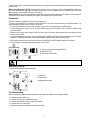
• Remove the small transparent plate on the rear panel to gain access to the voltage selector and terminal block.
• Set the voltage selector to either 120V for 100-120V 50/60Hz single phase AC supplies or 240V for 220-240V 50/60Hz single
phase AC supplies.
• Route the mains supply cable through the entry point to the right of the recess, and couple the cable to the terminal block as
shown on the rear panel.
• There are two alternative connectors. One accepts 20mm rigid or flexible conduit, and the other accepts three core 0.75 square
millimetre PVC sheathed mains cable (via the screwed adapter supplied) so that a mains lead can be used.
• Ensure that the mains lead is securely retained in the strain relief gland so that IP55 ingress protection is maintained.
• Securely replace the transparent plate and the gasket over the recess.
1 Armoured cable strain relief gland GR 0018
2 Washer GR 0019
3 Strain relief gland GR 0031
Ingress protection standard will be compromised if the transparent plate is not replaced.
Rear panel recess
The pump rear panel recess houses the following:
1 Fuse holder
2 Terminal block
3 Voltage selection switch
Troubleshooting
Should the pump fail to operate, make the following checks to determine whether or not servicing is required.
• Check that the power switch is on.
• Check the mains supply is available at the pump.
• Check the voltage selector switch is in the correct position.
• Check the fuse in the mains socket.
• Check that the pump is not stalled by incorrect fitting of tubing.
4
User interfacing
When powering up the pump the user will be taken into the main menu.
Use the Step key to move between menu options. Use the Enter key to confirm settings. Use the number keys to enter in
settings. Use the ¿ or À key to increase or decrease set values in the pump software i.e. ramp settings, date, rpm etc.
Dose permits the set-up of dose programs for dispensing. A dose can be initiated by using the Start button or external switching.
The pump will allow up to 26 dosing programs to be stored and recalled at any time. A printer can be connected to the pump for
recording of dispense runs. Batch and operator codes must be entered when using a printer.
Cal allows the pump to be calibrated for accurate dosing.
Manual allows continuous transfer/fluid metering via keypad control.
Auto enables analogue or RS232 control.
Setup displays and controls the user and factory settings for the correct operation of the pump.
The speed/volume flow rate of the drive is governed by the pumphead and tubing selected.
Dosing procedure
The Dosing program is outlined in the technical data section of the operating instruction in a flow chart format. Each step in the
procedure is described to provide full understanding of the procedure.
Within the technical data section are mean values for dose time guidelines and accuracy figures recorded using Silicone tubing at
zero suction and pressure. For the highest accuracy use small bore tubing and maximum roller passes. Always use a calibration
dose to ensure the highest accuracy possible.
Print audit routines
If a printer is connected, the completion of a dose run will automatically call the print routine. The first request will be to enter the
operator ID.
Up to 16 characters can be entered. Digits and the decimal point are entered directly from the keypad. Alpha characters are entered
by pressing ¿ or À which call A to Z and Z to A respectively in circular rotation.
An alpha character is embedded by pressing Step. A numeric character is entered by pressing Step, any other numeric
character, the decimal point or ¿ or À.
On pressing Enter, the pump will request the input of a batch number.
Again, up to 16 characters can be entered as for the operator ID. When Enter is again pressed, the following information is printed
out: date, time, dose size, specific gravity, dose interval, number of doses, initial ml/rev, recalibration data, operator ID, batch
number and number of doses delivered.
Following the print out a repeat dose option will be given.
Single dose command
Single doses can be dispensed on demand, with a count of the number of doses being kept.
Set the interval time to 0 SECONDS and the number of doses to 1.
To start single dosing, press Start or use an external start dose switch. The display will indicate the total number of completed
doses up to a maximum of 99,999 after which the counter will restart at 0, so that dose 100,001 would be shown as 1.
Calibration procedure
Calibration of the 605Di is based on informing the pump under Cal of the pumphead and tubing which are to be used. Alternatively
a calibration dose can be used. The calibration dose will run for a maximum of 4 minutes, but can be stopped at any time up to 4
minutes. The longer the calibration dose the more accurate the calibration. Entering into the pump the physical volume or mass to
complete the procedure and will allow the pump to take into account ambient conditions and also the viscosity of the fluid.
Manual operation
•
•
•
•
Switch power on.
Change the set speed by pressing the ¿ or À key. The minimum speed of the 605Di is 4 rpm.
Change direction by pressing the CW/CCW key. Indication of direction of rotation is provided via the LCD display.
Select the maximum speed: press the ¿ key and the Max key together. Select the minimum speed: press the À key and the
Max key together.
• Press Start to start the pump. Press Stop to stop the pump.
Auto
The pump will accept external control signals through the 25 pin cage clamp connector on the back panel. Remove the cover plate
ensuring that the gasket is not damaged. Feed the control wires through the cable glands and connect via the sprung cage clamps.
Analogue
This function enables the pump speed to be controlled via an external analogue process signal. Pressing Enter at analogue will call
a confirmation of the analogue control signal settings. These can be reset under Setup (see section covering pump setup).
RS232
5
This facility gives full pump functionality under RS232 closed loop control via the 4 pincage clamp. Up to 16 pumps can be linked
whilst still retaining individual pump control by using lead PR 0036. A network kit is available from Watson-Marlow which includes
Pumpnet 2, a DOS compatible control program and leads.
Step to Network in the Main menu and press Enter. The pump will now be under RS232 control. The keypad Stop key will act
as an emergency stop and disable RS232 settings if pressed.
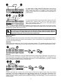
Connections for RS232 signals, 1 = GND, 2= RX, 3 = TX, 4 = CTS
RS232 cabling shown for CTR handshake
Use only twin shielded RS232 cables.
RS232 settings
Baud = 9600 ; Stop bits = 2 ; Data bits = 8 ; Parity = None ; Handshake = CTR or None; Auto echo = On
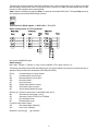
The following codes will operate the 605Di under RS232 control. They must be directed to the pump from a computer serial port (or
equivalent). Always terminate each command with a RETURN (ASCII CHR13).
nSPxxx
Load speed setting xxx to pump number n
nSI
Increment speed by 1rpm for pump n
nSD
Decrement speed by 1rpm for pump n
nGO
Start pump number n
nST
Stop pump number n
nRC
Change rotation direction for pump n
nRR
Set clockwise direction for pump n
nRL
Set anti-clockwise direction for pump n
nDOxxxxx,yyy Set dose for pump number n in tachometer pulses (note 3)
nRS
Show status for pump number n (note 4)
nZY
Show status if pump n STARTed 1 or STOPped 0
nTC
Clear tachometer counter
nRT
Read tachometer counter
For writing to pump number n display
nCA
Clear existing display; followed by:
nCH "
Home" cursor; followed by;
nW{text line 1}~{text line 2}@ ( @ = terminator )
6
Notes on control codes
1 n = pump number set in SETUP. For the command to operate on all networked pumps simultaneously, use # before the
command.
2 There are 1046 tacho pulses per revolution at the maximum drive speed of 200rpm.
3 nDOxxxxxxxx where xxxxxxxx is any integer and is the target dose in tacho pulses. This can be extended to nDOxxxxxxxx,yyy
where yyy is a "kick back" in tacho pulses with a limit of 255 (about 1 revolution on a 200rpm drive).
4 A show status command will prompt the 605Di to return a text string of the following layout:
[pump type] [ml/rev] [pumphead] [tube size] [speed] [cw/ccw] [P/N] [pump number] [tacho count as a single integer]
[stopped/running, 0 /1] [! = delimiter]
eg 605Di 0.7 605L 4.8mm 100 CW P/N 1 157810 1 !
5 All networked pumps with the same n will respond to the same command.
6 There should be at least 10mS between consecutive commands.
7 When using the # to address all pumps, ensure that it will not generate a reply, eg nSS, the result will be unpredictable.
This is a typical short program for pump number 2:
OPEN "COM1:9600,N,8,2,CDO,CSO,DSO,OP10000" FOR RANDOM AS #1
PRINT #1, "2SP220" + CHR$(13)
DELAY (command depends on language being used)
PRINT #1, "2GO" + CHR$(13)
DELAY 5000
PRINT #1, "2ST" + CHR$(13)
CLOSE #1.
Setup
ROM - provides user with software identification.
Date/Time - Set during manufacture but can be reset to user requirements.
Beep - Audible signal on/off.
Ramp - Rate of acceleration/deceleration of the pump to/from maximum set speed at the beginning/end of a dose. 0 setting
signifies no acceleration delay to maximum speed, 5 signifies the longest acceleration delay to maximum speed.
Drip - Brief reversal of the motor on dose completion ensures no extra drips of fluid are dispensed. 0 means no reverse and 5
means maximum reverse.
Baud - Speed of signal transmission. Default setting 9600, range of setting include 1200, 2400, 4800, 9600.
Auxiliary - Monitor the pump dosing or motor state/direction of rotation using 2 high (5V) /low (0V) auxiliary signals outputted via
the pumps 25 pin cage clamp connector. Auxiliary signals can be used, for example, to command a turntable or conveyor to move
when a dose has been completed.
Line 1 can be set to change state every time the motor runs, or only when the motor runs to dispense a dose. The signal can be set
high or low when the motor runs. Line 2 changes state when the pump direction is changed. The screens allow the signal to be set
high or low when the output shaft rotates clockwise.
Pump - When under RS232 control each individual pump must be identified. Select a number from 1-16.
Max - Sets when the pump can be primed at maximum speed. Standard setting means Max is enabled during Manual and Setup.
Always enabled means the unit can be primed at any time.
Default - Press Enter at "Yes" to restore factory defaults.
Autostart - If set to On when in Manual mode only, Autostart will allow the pump to restart pumping automatically after powerup following a mains supply interruption. If set to Off the pump will restart and return to the Main Menu.
Signal - Step to the desired process signal for analogue control and press Enter. Options available are 4-20mA, 0-10mA, 020mA, 0-5V, 0-10V These signal ranges correspond to 0-200rpm speed control. A confirmation screen will verify settings chosen. If
the signal type required is not shown then use the "program " option to enter in the required signal levels. The pump is controllable
by an analogue process signal of up to 30V or 32mA. The pump will provide an increasing flow rate for a rising control signal (noninverted response) or an increasing flow rate for a falling control signal (inverted response).
7
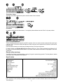
For voltage modes a stable, variable DC voltage source can be used in
conjunction with a DC voltmeter, (max 30V DC). (Refer to the 25 pin cage
clamp connector wiring detail as an example of control circuitry) Circuit
impedance 100kΩ. Polarity set for non-inverted response. Reverse polarity for
inverted response.
For current modes the same DC source can be used in conjunction with a DC
milliampere meter, (maximum 32mA). (See 25 pin cage clamp connector
detail). Circuit impedance 250Ω. Polarity set for non-inverted response.
Reverse polarity for inverted response.
Trim - This function will match the pumps signal conditioner to the analogue process control signal if they do not fully coincide.
The user will be asked to apply zero, 20% and the maximum voltage or current that is required to be the control signal. Press enter
after adjusting the process signal to each input level.
Never apply mains voltage across pins on the 25 pin cage clamp connector. Up to 5V TTL may be applied to
pins 7 and 5, but do not apply voltage across any other pins. Failure to heed this warning could cause
permanent damage not covered by warranty. Do not use the mains power switch to control the pump for a
high repetition of stop starts. The auto-control facility should be used.
Remote control
Pause dose
This function will pause a dose on for as long as a remote switch remains closed then allows the dose to continue when the switch
is opened. Under Manual mode it will also act as a remote stop/start. Connect remote switch as in the Stop/Start diagram. Open to
run pump, close to pause or stop pump.
Stop/Start
Connect remote switch between pins 7 and 16 of the 25 pin cage clamp connector. A TTL compatible logic input (Low 0V, High 5V)
may be applied to pin 7. Low input stops the pump, high input runs the pump. With no connection, the pump will default to running.
Direction
Connect remote switch between pins 5 and 16 and disable the front panel reversing control by linking pins 6 and 18 of the 25 pin
cage clamp connector. Open switch for clockwise rotation, close for counter-clockwise. Alternatively a TTL compatible logic input
(Low 0V, High 5V) may be applied to pin 5. Low input will run the pump in a counter-clockwise direction, High input in a clockwise
rotation. No connection; the pump will default to clockwise rotation.
Speed
A remote potentiometer with a nominal 1kΩ and 2kΩ minimum 0.25W should be wired as shown. When using a remote
potentiometer, do not apply a voltage/current control input signal at the same time. The pump must be calibrated for 0-12V
analogue signal control under the "PROGRAM" option of Signal in Setup. Alternatively, the potentiometer may be used for the
calibration procedure, instead of using the minimum and maximum analogue process signal settings, if it is set to its minimum and
maximum positions.
8
Tachometer output
This facility can be used to indicate motor speed or total the number of motor revolutions.
Footswitch
A footswitch or hand switch will initiate the dose. If not supplied by Watson-Marlow then select "Other" in the pumps software.
5V
0-5V DC
Care and maintenance
The only scheduled maintenance required for the 605Di is inspection of the motor brushes and their replacement before their length
is less than 10mm. The life of the brushes will depend on the duty of the pump, but is expected to be a minimum of 4,000 hours at
maximum speed.
If the pump requires cleaning, use a mild solution of detergent in water. Do not use strong solvents.
For gearbox rebuilds, use Lubriplate GR-132 (Bodine reference LG-23) only. This is a lithium combination type thickener, NL GI
No.1 grade, non-corrosive extreme pressure lubricant. This product is water resistant and resistant to a large degree to most other
contaminants.
Guard safety warnings
The 605Di will be remotely stopped and display a warning if the guard is opened during operation. This safety feature is enabled
under Manual, Dose, Analogue and RS232 operation.
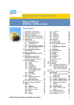
Specification
Maximum rotor speed
Voltage/frequency
Control range
Power consumption
Fuse rating
Operating temperature range
Storage temperature range
Weight 605Di/R
Weight 605Di/L
Noise
Standards
200rpm
100-120/220-240V 50/60Hz
50:1
300VA
Type T (anti-surge) 5A
5 to 40C
-40C to 70C
24.75kg
30.75kg
<72dBA at 1m
IEC 335-1, EN60529 (IP55)
Machinery Directive 89/392/EEC EN60204- 1
Low Voltage Directive 73/23/EEC EN61010- 1
EMC Directive:89/336/EEC EN50081-1 / EN50082-1
Specific drive performance details such as loaded drive speed variation against mains supply voltage fluctuation and drive stability
from a cold start to normal operating temperature are available on request. For further information please contact Watson-Marlow
Technical Support.
9
Flow rates
Flow rates for the 605Di/R &605Di/L were obtained pumping water at 20C with negligible suction and delivery pressures (unless
otherwise stated). Where an application is critical, the flow rate should be determined under operating conditions. The important
factors are suction and delivery pressures, temperature and fluid viscosity.
603R pumphead
The 603R has two spring loaded rollers, which automatically compensate for minor variations in tubing wall thickness, giving
extended tube life.
The 603R is set during manufacture to accept a nominal tubing wall thickness of 3.2mm and bore sizes of between 4.8mm and
15.9mm.
The pumphead can be run clockwise for extended tube life or anti-clockwise to operate against higher pressures.
603R/605L guard wiring
Remove the top half casing from the drive. Pass the switched guard wires through the front panel of the drive and connect to the
terminal blocks as shown below. Replace horizontal, front and back panel case gaskets to ensure the IP55 ingress protection
standard is not compromised. Replace top half casing.
1
2
3
4
5
6
Green
Red
Blue
Black
Yellow
Red
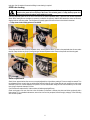
Fit the track over the drive shaft and locating boss. Secure the track with the retaining screws. Ensure the drive shaft has been
completely degreased before locating the rotor onto the shaft via a split collet. Tighten the rotor bolt to a torque of 13Nm to prevent
the collet slipping during operation.
• Pump shown in track loading pictures is the 603S/R
To remove the track, remove any tubing from the pumphead. Loosen the rotor securing bolt and give the rotor/bolt a sharp tap to
free the collet. Release the collet, and withdraw the rotor from the shaft. Loosen the two track securing screws and pull the
10
track clear. Use this method of removal and fitting in case cleaning is required.
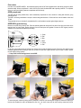
603R tube loading
Isolate drive from the mains supply. If the pump is not switched off before the pumphead guard is raised, a
switch on the guard will cut off power to the motor. This switched guard is a safety back-up system and
must not be used as the primary on/off switch for the pump.
Open the pumphead guard and fit one end of the tube into the bottom adjustable clamp. Tighten the lower serrated adjustment
wheel. Whilst rotating the rotor clockwise (a spanner is provided for this purpose), feed the tube between the rollers and the track,
aligning it with the rotor tube guides. The tubing must lie naturally against the track and must not be twisted or stretched.
• Pump shown in tube loading pictures is the 603S/R
Fit the other end of the tube into the top adjustable clamp, ensuring that the tube is not slack in the pumphead since this can reduce
tube life. Clamp the tube very firmly by turning the upper serrated adjustment wheel. Remove the spanner and close the guard.
Roller adjustment
Should it ever appear that the roller arms are not equally adjusted, the original factory setting of 5.2mm can easily be restored. Turn
the adjustment screws on each roller arm anticlockwise until both rollers are just in contact with the track, and then turn each screw
clockwise by five turns. Correct adjustment is important. For 4mm wall thickness tubing turn the screw clockwise by six and a half
turns giving a roller/track clearance of 6.6mm.
Over-occlusion will reduce tube life. Under-occlusion will reduce pumping efficiency.
Check moving parts of the rotor from time to time for freedom of movement. Lubricate pivot points and rollers occasionally with a
light machine oil. For scheduled maintenance, remove the rotor from the pumphead, clean thoroughly and apply Teflon lubricating
oil to the roller spindles.
11
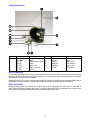
Pumphead spares
Number
1
2
3
4
5
6
7
Spare
GR 0008
MR 0258M
SW 0139
MR 0601T
MR 0571T
MR 0575T
MR 0573T
Description
Grommet
Guard
Guard switch & magnet
Collet
Roller - tube
Roller - tube guide
Spindle
Number
8
9
10
11
12
Spare
MRA0010A
SG 0003
MR 0572T
MRA0161A
MR0275M
XX 0095
Description
Rotor assembly
Spring
Roller - guide
Track assembly
Hinge - guard
Teflon lubricant
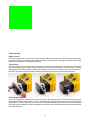
605L Pumphead
The twin offset track design of the 605L utilises 4.0mm wall double-Y tube elements to overcome pulsation for accurate dosing and
dispensing. The 605L accepts Silicone and Marprene tubing up to 16.0mm bore. Use 4.0mm wall tube for transfer for the highest
performance and improved viscous fluid handling.
Alternatively the 605L will run with two separate tubes although some channel to channel variance and minimal pulsation may be
experienced. For separate tube fitting or twin tube inlet to single tube outlet fitting tube clamping blocks must be used.
605L Installation
Remove the mounting plate cover and track from the 605L. Align the drive shaft dog and 605L centre shaft slot. Locate 605L to
pump. Tighten top and bottom mounting plate screws. To remove the pumphead lift off the mounting plate cover and track, loosen
the to and botton mounting plate securing screws and ease pumphead away from the pump.
12
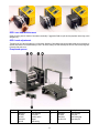
Tube loading
Double-Y element
Lift the track locating levers and remove track. Locate one end of double-Y element over one of the 605L clamping pegs. Stretch
the element over the rotor and locate the other end of the element over the second 605L clamping peg. Replace the track and push
down the track locating levers. (See pumphead installation).
Twin inlet tubes
Lift the track locating levers and remove track. Twist and remove the 605L inlet clamping peg. Connect the twin inlet tubes and
outlet tube using the appropriate y piece connector and clamps. Fit the inlet tubes into the correct size clamping block. Locate the
clamping block onto the 605L (push down and twist locking fastener to secure). Stretch the tubes over the rotor and locate the Ypiece end of the element over the second 605L clamping peg. Replace the track and push down the track locating levers.
Two independent tubes
Lift the track locating levers and remove track. Twist and remove the 605L clamping pegs. Fit the two tubes into the correct size
clamping blocks. Distance between blocks = 230mm for up to 8.0mm bore; 240mm for 12.0mm and 16.0mm bore. Fit the inlet tube
clamping block to the 605L. Stretch the tubes over the rotor and fit second tube clamping block to the 605L. Replace the track and
push down the track locating levers. When using Marprene it is important to check the distance between the clamping blocks after
30 minutes running time.
13
605L care and maintenance
Check all moving parts for freedom of movement occasionally. If aggressive fluids are spilt onto the pumphead, clean using a mild
detergent only.
605L track adjustment
The track is set for 4.0mm wall tubing up to 16.0mm bore. Alteration of this setting using the pan head screws may be necessary to
optimise performance if non-standard tubing is used. The factory setting is 20.3mm vertically from the rotor side of the sprung track
to the top of the track cover.
Pumphead spares
Number
1
2
3
4
5
Spare
MRA0141A
MR 0851S
SW 0050
MRA0143A
BB 0018
Description
Track assembly
Cover plate
Proximity switch
Adaptor
Shaft bearing
Number
6
7
8
9
14
Spare
MRA0150A
MR 0850S
MRA0144A
069.4001.000
Description
Rotor assembly
Front plate
Tube locating peg
Tube clamp set
Drive spares
Number
1
2
3
4
5
6
7
8
9
10
Spare
MRA0194A
MRA0193A
MR 0289S
MRA0198A
MRA0195A
MR 0699S
FS 0043
CP 0005
MR 0771S
MN 1087S
Description
PCB Hbridge
IC ROM
Chassis
Transformer
PCB cardinal
Window cover
Fuse 5 amp T type
Blanking plug OD 20mm
Window gasket
Window gasket
Number
11
12
13
14
15
16
17
18
19
20
15
Spare
CP 0020
MN 1086S
FN 0215
FA 0002
MN 0787M
MN 0690S
BM 0015
MR 0771S
TM 0020
MG 0600
Description
Blanking plug
Window cover
M4 screw
Filter
Tacho Disc
Gasket
Motor brush
Gasket
Terminal block 10A 12 way
Motor/gearbox
Outline dimensions
605Di/R
605Di/L
16