1
AGH University of Science and Technology
Faculty of Electrical Engineering, Automatics, Computer Science and
Electronics
Department of Electrical Machines
Name:
Jakub Wójcik
Faculty:
Electrical Engineering
Specialization:
Computer Engineering In Electrical Systems
The conception and the implementation of control
system for servomotor with application of wireless
network
Master’s thesis written
under the direction of
prof. dr hab. inż
Zygfryd Głowacz
Kraków 2011
STATEMENT OF ORIGINALITY
Aware of criminal liability for making untrue statements I declare that the following
thesis was written personally by myself and that I did not use any sources but the
ones mentioned in the dissertation itself.
…………………………………
/date/
………………………………..
/signature/
2
Sincere thanks to
prof. dr hab. Inż Zygfryd Głowacz
for a thematic approach
and his help during the writing process
3
Table of Contents
Unit I
A Little bit of theory ........................................................................................... 6
1.1.
Servo – What and how ....................................................................................................... 6
1.2.
Wireless Network – 802.11 ................................................................................................ 9
Unit II
Hardware/software ........................................................................................... 11
2.1.
Open Source – nice, simple and free ............................................................................... 11
2.2.
Arduino Uno ..................................................................................................................... 12
2.3.
WiFly Shield ...................................................................................................................... 16
Overview ...................................................................................................................................... 17
Unit III
Conception of Control System ........................................................................ 18
3.1.
The idea ............................................................................................................................ 19
3.2
Applications ...................................................................................................................... 24
Unit IV
Implementation of Control System ................................................................ 26
4.1
Hardware .......................................................................................................................... 26
4.2
Software ........................................................................................................................... 31
4.3
Observations .................................................................................................................... 54
Conclusion…... ........................................................................................................................ 57
Bibliography ............................................................................................................................ 58
Appendix A – Arduino Uno Schematics ............................................................................... 62
Appendix B – WiFly SparkFun Schematics ......................................................................... 62
Appendix C – Arduino Source Code .................................................................................... 64
Appendix D – Delphi Source Code ........................................................................................ 87
Appendix E – Project on CD ............................................................................................... 118
4
Introduction
World runs faster and faster everyday. New inventions appear in every corner of the
world. This is the fact. But the reason why can not be more prosaic. People are lazy…
Everybody wants not to have to do as many things as possible. That is why intelligent
buildings becomes more and more popular, cars park themselves, vacuum cleaners drive
under our feet and even more. We simply do not know in how many different fields we are
being replaced by machines.
Following the trend I have decided to focus on the
conception of control system for servomotor with application of wireless network. Why to
do something that can be done by a machine behind the wall…?
I have tried to come up with all-purpose solution that could be adopted not only in
industry or in everyday life but also by academics as quite interesting laboratory exercise. I
am not the one who should rate my work but I think that I can be a little pleased with the
effects of my work. Just a little bit.
In the first unit I have focused on theory that is needed to fully understand the
whole concept. Few words about servomechanisms and wireless networks can be found
there. Of course due to size limit of my master‟s thesis there are just strict basics.
Second unit consists of description of hardware and software I have used in this
project. All open source, all simple and what‟s most important… it is working.
Third unit brings up to the light the essence, conception of whole project along with
example applications of control system. This unit is theoretical.
And in the end the time has come to present whole practical process of creation.
Here you can find report about how does it come to life.
5
Unit I A Little bit of theory
1.1. Servo – What and how
To start solving the problem of wireless control system for servomotor we must be
aware of what the servomechanism really is.
Servomechanism1 it is an automatic control system in which the output is
constantly or intermittently compared with the input through feedback so that the error or
difference between the two quantities can be used to bring about the desired amount of
control.
The key to understand this is a term “feedback” or “error-correction”. For example,
an automotive power window control is not a servomechanism, as there is no automatic
feedback that controls position (operator does it by him/herself). However the car‟s cruise
control uses closed loop feedback, which classifies it as a servomechanism.
Servomechanisms with or without motors are used in our everyday life. But we will focus
on particular type that uses DC motor - servomotor.
Servo is a device with a shaft on the outside. The idea is that the shaft can be
positioned in a certain angular position by sending appropriate signal to the servo. When
the signal line is maintained constant shaft‟s position will be unchanged. Any changes in
signal line causes immediate changes in shaft position.
The construction of servo
is based on normal DC motor with
extra gear and control system. The
control system can accurately
determine the position of motor as
shaft rotates the rotary knob which
allows us to position the shaft
with great accuracy. The control
system sets the shaft, depending
on the length of the control pulse
on the line sampled every 20ms.
Figure 1. Construction of the servomotor
In most cases, servomotors are
[source: http://www.engineersgarage.com/articles/servo-motor]
1
http://www.yourdictionary.com/servomechanism
6
designed to take position angle between 0 and 180 degrees. Most mechanisms have
limiters that do not allow a greater swing of the shaft. In fact, servos are mainly used in
positioning systems such as cameras, electronic equipment equipped with mechanical
positioning, aircraft models to set primaries. Those applications put pressure on accuracy,
ease of operation and low power consumption instead of full rotation. Wherever full
rotation is needed stepper motors or DC motors are used.
The servomotor is connected with control system with three wires: positive supply,
ground and control signal. These wires are color coded. The red wire is the DC supply and
must be connected to a DC voltage supply in range of 4.8V to 6V. The black wire is to
provide ground and third one which occurs in variety of colors to provide control signal.
Unlike DC motors it is important not to revers ground and supply connections due to
possibility of damaging servo.
Moving shaft to a desired angular position is obtain via a control line by pulsewidth modulation (PWM). The location of the shaft is set to an appropriate length of the
pulse on this line. Servo has a built-in 50Hz generator. It means that in every 20ms control
line signal of appropriate length should be given to maintain control. The standard for most
Figure 2. Pulse servo control
[source: http://www.engineersgarage.com/articles/servo-motor]
7
of the servos is a shaft of 1.5ms pulse length for the center position set. Deviate from this
value causes the shift shaft move to the left or to the right. In most motors pulses are in the
range between 1 - 2ms.
In practice (servo used in this project is Hextronik HXT900) it appears that for the
zero position to be maintained the 0.95ms pulse is needed, the middle position - 1.5ms,
1.95ms for final position.
Figure 3. Servo motor system schematics
[source: http://www.engineersgarage.com/articles/servo-motor]
8
1.2. Wireless Network – 802.11
Since the beginning wires were the main restriction of every control mechanism.
Due to this limitation human factor at specified time and place to control every wired
device, or expensive and complicated wired network is needed. But what if we were able
to bypass this “little” obstacle? One person controlling many devices spread over a large
area without necessity of additional equipment.
To achieve this goal wireless networks were created. As development of wireless
networks and wireless networking from the very beginning goes hand in hand we can say
that it all started in the 1800‟s with the discovery of radio technology.
The year was 1888, Hamburg. Here German physicist named Heinrich Rudolf Herz
produced first radio wave ever. It took only 6 years to introduce radio technology to
everyday use. By the 1984 radio waves became a way of communication. Herz opened the
way for radio, television, and radar with discovery of electromagnetic waves. But the title
of the ”father of the radio” was taken by an Italian inventor Marchese Guglielmo Marconi
who expanded the radius of radio wave sending to two miles. In the next step Marconi
could send signal 9 miles across the Bristol Channel and eventually expanded the radius to
31 miles across the English Channel to France. By 1901 the communication area stopped
becoming a boundary. Marconi was able to send signals across the entire Atlantic Ocean.
The biggest step for the radio wave was the World War II when for the first time
radio data transmission was used. The United States was the first party which managed to
control sending information via radio waves. Many people believe that this application
largely contributed to the final victory. After the WWII in 1971 a group of researchers
under the lead of Norman Abramson from the University of Hawaii created the first
“packet-switching” radio communications network entitled “ALOHAnet”. It was the very
first official WLAN(wireless local area network) with the application of star topology
created ever. In the 1972 the connection between ALOHAnet and Arpanet on the mainland
was achieved. The length of this connect was crucial in the telecommunications between
computers.
The first types of WLAN technology used and unlicensed band (902-928 MHz),
which later became crowded with interface from small appliances and
industrial
machinery. A spread spectrum was used to minimize this interference which operated at
500 kilobits per second. The second generation of WLAN technology was operating at
9
2Mbps. The third generation which we use nowadays operates on the same band as the
second generation, 2,4GHz.
The world first official standard IEEE 802.11 with data rates of 1 and 2 Mbps was
established in 1997 seven years after IEEE 802 Executive Committee established the
802.11 Working Group to create a wireless local area network (WLAN) standard.
That is history. Now let‟s focus on the protocol itself. The 802.11 family consists of
series of over-the-air modulation techniques that use the same basic protocol. The most
popular are defined by 802.11b and 802.11g protocols. The most up to date protocol is
802.11n but due to relatively expensive devices it is not as popular as previous versions.
802.11 network standards2
802.11
protocol
-
a
b
g
Release
Jun
1997
Freq.
Bandwidth
(GHz)
(MHz)
2.4
20
Sep
5
1999
3.7
Sep
1999
June
2003
20
2.4
20
2.4
20
Data rate (Mbit/s)
Approximate range
indoor
Outdoor
1, 2
20
100
6, 9, 12, 18, 24, 36,
35
120
48, 54
-
5000
5.5, 11
38
140
38
140
70
250
70
250
6, 9, 12, 18, 24, 36,
48, 54
7.2, 14.4, 21.7,
n
Oct
2009
20
28.9, 43.3, 57.8, 65,
72.2
2.4/5
40
15, 30, 45, 60, 90,
120, 135, 150
As we can see in the chart above we will focus only on protocol versions that are or
that were used in wlan european networks. All the other can be found on the website of
IEEE 802.11 Executive Committee3.
2
3
http://standards.ieee.org/findstds/interps/
http://www.ieee802.org/
10
Unit II Hardware/software
2.1. Open Source – nice, simple and free
Since the beginning of the computer history the intellectual property rights were the
issue. Every man wants to be rewarded for hard work, that is fully understandable. But due
to that fact accessibility to the new technology in fast changing IT world is restricted for
those who do not have enough resources to be up to date. This is where Open Source
license software comes across. The idea of creating software with license that provides free
access to the software for all users. The criteria that software must meet with in order to be
qualified as open are: free distribution, object code, source code distributed with the
program and any of its modifications.
This is, for some people unusual, view over licensing bring to the world opportunity for
people all over the world to create much bigger and more complicated projects. For
example Apache HTTP Server, e-commerce platform osCommerce, GNU/Linux operating
systems or Unix-like operating systems.
In my work I have decided to use a part of software created “by people, for people”.
Arduino Uno prototyping platform is what I have chosen.
11
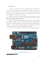
2.2. Arduino Uno
„Arduino is an open-source electronics prototyping platform cased on flexible,
easy-to-use hardware and software. It’s intended for artists, designers, hobbyists and
anyone interested in creating interactive objects or environments”. Those are the very first
words we meet on the Arduino project website4 and after familiarizing myself with this
“new” platform for me I can say they are very truth.
Arduino Uno is the latest version of the motherboard I have decided to use in this
project as the variety of inputs and outputs which can be used for sensors or to control
lights, motors and other actuators are provided.
Another very pleasant solution implemented in Arduino board is the programming
language(based on Wiring* - open source programming environment) created especially
for the needs of the microcontroller and Arduino development environment(based on
Processing* - also open source programming language). To communicate with software
running on computer Flash, Processing or MaxMSP are recommended.
Open source and relatively new concept cause the fact that documentation is
Figure 4. Arduino Uno – Front
[source: http://arduino.cc/en/Main/ArduinoBoardUno]
4
http://arduino.cc/en/
12
provided mostly in wiki-like and forum form which is bothersome when meeting problems
during development process. Experience shared with other developers helps to improve
following versions of Arduino board but lack of the old fashioned technical specification
forced me to look through countless data in order to find needed information.
The Arduino Uno is microcontroller equipped with ATmrga328. It has 14 digital
I/O pins of which 6 can be used as PWM outputs, 6 analog inputs, a 16 MHz crystal
oscillator, a USB connector, a power jack an ISCP header, and a reset button. The main
difference between other solutions available is the lack of the FTDI USB-to-serial driver
chip. Instead the ATmega8U2 programmed is supported as a USB-to-serial converter.
The board can be powered via USB, DC adapter (wall-wart) or battery. The power
source is selected automatically. To use AC to DC adapter we need 2.1mm center-positive
plug power jack. Battery can be connected either to USB, power jack or inserted in Gnd
and Vin pin heads of the POWER connector. The recommended range of supply is 7 to 12
volts despite limits of 6 to 20 volt due to the fact that voltage lover than 7V makes 5V
onboard pin unstable and voltage higher then 12V can lead the voltage regulator to
overheat and directly damage the board.
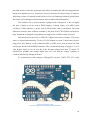
To communicate with computer ATmega8U2 provides UART TTL (5V) serial
Figure 5. Arduino Uno – Back
[source: http://arduino.cc/en/Main/ArduinoBoardUno]
13
communication over USB (available on digital pins 0 RX and 1 TX). After connecting to
the PC it appears as a virtual com port to software on the computer. No additional drivers
are needed as „8U2 firmware uses the standard USB COM drivers. To control data flow
RX and TX LEDs will flash when data is being transmitted via USB-to-serial chip and
USB connection to the computer (not for serial communication on pins 0 and 1).
As it comes to programming Arduino Uno can be programmed with software
provided. The board is preburned with bootloader that allows to upload new code to it
directly via USB, no external hardware programmer needed. It communicates using
STK500 protocol. If needed, it is also possible to bypass bootloader using the ICSP (InCircuit Serial Programming) header.
Very important thing is the USB overcurrent protection in which board is equipped.
Resettable polyfuse protects computer‟s USB ports from shorts and overcurrent. The
connection is automatically broken if more than 500 mA is applied. After removing short
or overload connection goes back to normal.
Summary
Microcontroller
ATmega328
Operating Voltage
5V
Input Voltage (recommended)
7-12V
Input Voltage (limits)
6-20V
Digital I/O Pins
14 (including 6 PWM)
Analog Inputs Pins
6
DC Current per I/O Pin
40 mA
DC Current for 3.3V Pin
50 mA
Flash Memory
32 KB (ATmega328), 0.5KB used by
bootloader
SRAM
2 KB (ATmega328)
EEPROM
1 KB (ATmega328)
Clock Speed
16 MHz
Dimentions
2.7x2.1 inches (USB and powe jack beyond)
Schematics availble in “Appendix A – Arduino Uno Schematics” on page 62
14
There are many reasons for choosing this solution as base for whole project. First of
all I have assumed that in this case reinventing the wheel is not a good idea. As I am not
electronic engineer creating board like this alone bears significant risk of failing due to the
lack of experience. Second one is the wireless shield provided by another producer with
whole set of technical documentation. And the third one, Arduino Uno provides far more
than I need for a reasonable price.
15
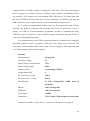
2.3. WiFly Shield
As Arduino Uno which plays
role of the motherboard is very
capable of talking and listening
(controlling
I/O),
it
is
not
equipped with key for this project
communication capability which
is wireless IEEE 802.11 protocol.
To achieve this requirement I was
forced to look for addition that
does. After few days of searching
I have come up with WiFly shield
form SparkFun Electronics that
allows
to
connect
to
the
802.11b/g wireless network.
The revision of WRL-09954
Figure 6. WiFly SparkFun Arduino shield
[source:http://www.sparkfun.com/products/9954]
is an addition shield for arduino platform equipped with Roving Network‟s RN-131C
wireless module, an SC16IS750 chip and supporting components. The usage of SPI-toUART bridge accelerates the transmission speed and frees up the Arduino‟s UART. The
only restriction, as the power is taken directly from Vin pin of the Arduino regulated to
3.3V, is the communication between WiFly shield and Arduino itself. The communication
goes over SPI using digital pins 10 to 13(CS, MOIS, MISO, SCLK respectively) what
makes them unusable for programming purposes. But, on the other hand, thanks to the
prototyping area with 0.1” spaced holes placed on the shield, I was able to place few
improvements without placing another printing shield what decreased the final dimensions.
The technical support came as:
-
“WiFly GSX User Manual and Commend Reference5”,
-
“SC16IS750 Datasheet6”,
-
Schematics available in Appendix B – WiFly shield schematics on page …,
-
“experimental WiFly shield code library7” which in the end I have decided not to
use,
5
6
http://www.sparkfun.com/datasheets/Wireless/WiFi/WiFlyGSX-um2.pdf
http://www.sparkfun.com/datasheets/Components/SMD/SC16IS740_750_760.pdf
16
-
“Talking Wireless Serever Tutorial8”,
-
Two forums Arduino9 and SparkFun10
Overview
-
Fully Qualified and Wi-Fi Certified 2.4GHz IEEE 802.11b/g transceiver,
-
High throughput, up to 4Mbps sustained data rate with TCP/IP and WPA2,
-
Ultra-low power (4µA sleep, 40mA Rx, 210mA max Tx),
-
On board ceramic chip antenna and U.FL connector for external antenna,
-
8 Mbit flash memory and 128 KB RAM,
-
UART and SPI (future) data/control interfaces,
-
10 general purpose digital I/O
-
8 analog inputs,
-
Real-time clock for wakeup and time stamping/data logging,
-
Accepts 3.3V regulated or 2-3V battery with on board boost regulators,
-
Supports Adhoc and Infrastructure mode connections,
-
On board ECOS-OS, TPC/IP stacks,
-
Wi-Fi Alliance certified for WPA2-PSK,
-
FCC/CE/ICS certified and RoHS compliant,
Features
-
Host Data Rate up to 1 Mbps for UART, 4Mbps SPI,
-
Memory 128KB RAM, 2MB ROM, 2KB battery-backed memory, 8Mbit Flash,
-
Intelligent, built-in power management with programmable wakeup,
-
Can be powered from regulated 3.3VDC source or 2.0-3.0V batteries,
-
Real time clock for time stamping, auto-sleep and auto-wakeup modes,
-
Configuration over UART or wireless interfaces using simple ASCII commands,
-
Over the air firmware upgrade (FTP), and data file upload,
-
Secure WiFi authentication WEP-128, WPA-PSK (TKIP), WPA2-PSK (AES),
-
Built in networking applications DHCP client, UDP, DNS client, ARP, ICMP ping,
FTP, TELNET, HTTP,
-
802.11 power save and roaming functions
7
http://forum.sparkfun.com/viewtopic.php?p=115626#p115626
http://www.sparkfun.com/tutorials/158
9
http://arduino.cc/forum/
10
http://forum.sparkfun.com/
8
17
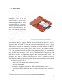
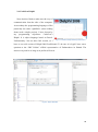
2.4 CodeGear Delphi
Next decision I had to make was the way of
communication from the side of the computer.
As nowadays the programming languages offers
practically the same capabilities (when talking
about such a simple project), I have chosen by
my
programming
experience
CodeGear‟s
Delphi. It is object language based on Pascal.
Unfortunately I do not have full version, so I
Figure 7. CodeGear Delphi 2009 by Embarcadero
Technologies.
have to use trial version of Delphi 2009 Proffesional. To be sure it is legal I have sent a
question to the “BSC Polska” official representative of Embarcadero in Poland. The
answer was positive as long as no profits will occur.
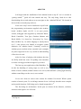
Figure 8. Delphi 2009 GUI
18
Unit III Conception of Control System
3.1. The idea
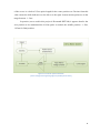
Every project begins with the idea. In this case the main idea was to control servomotor
via wireless IEEE 802.11 network. To achieve this goal following establishments has been
considered. Main schematic diagram as follows.
Figure 9. Schematic diagram of the control system for servomotor with application of wireless network
1. Every PC with installed WCC (WirelessControlClient) application on it is enough.
In further future applications on Windows Mobile, Android, Symbian or iPhone are
possible to create.
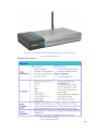
2. As 802.11 protocol is basically used in small wireless networks either access point
with DHCP server or ad-hoc connection between computer and control system was
required. In this case I have used D-Link DSL-G684T. Wireless G 54M ADSL2+
Modem Router w/4 Port 10/100 Switch capable to test connection wifi-wifi as well
as ethernet-wifi.
19
Figure 10. D-Link DSL-G684T ADSL2+ 54M Wireless Router w/ 4 Port 10/100 Switch
[source: DSL-G684T Manual]
Technical Specifications:
Picture 11. General Specification
[source: DSL-G684T Manual]
20
Picture 12. Physical and Environmental Specification
[source: DSL-G684T Manual]
Picture 13. Wireless Specification
[source: DSL-G684T Manual]
21
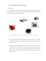
3. As a control system I have used Arduino Uno mainboard with additional WiFly
SparkFun shield. Both are described with technical specifications in Unit II. For the
project the control system is called WCS (WirelessControlSystem).
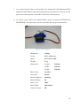
4. To control I have chosen two simple hobby 9 gram servomotors HXT900 from
HEXTRONIK. The main factor was low cost and relatively good construction.
Figure 14. Hextronik HXT900
Modulation:
Analog
Torque:
4.8V: 1.6 kg-cm
Speed:
4.8V: 0.12 sec/60˚
Weight:
9.1 g
Dimensions:
Length:
21.0 mm
Width:
12.0 mm
Height:
22.0 mm
Motor Type:
Coreless
Gear Type:
Plastic
Rotation/Support:
Bushing
Rotation Range:
90˚
Pulse Cycle:
20ms
Pulse Width:
450-2450 µs
Connector Type:
JR
22
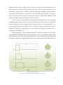
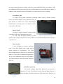
5. As all new inventions without the suggestion of application are rather meaningless,
I have decided to make this project a little bit more “alive” by adding one. To do
this the BlackBox was created. Inside a small photocell and one servomotor are
hidden. The purpose of this box is to maintain previously set intensity of light
inside. Top of the box works like blinds in the windows. Servomotor controls
obscure of the blinds while photocell checks light intensity.
23
3.2 Applications
The main issue of new inventions are the applications. History of human kind is full of
meaningless gadgets created without explicit purpose that land on shelves and are never
used again. I have spent many hours of work and hard thinking on this project and I would
like it not to happen. That is why here are just a few examples of application of the control
system of servomotors via wireless network.
Stage light control – separately controlled stage lights with ability of preprogrammed
movement scenario or manually controlled. In the fact the only limitation in the number of
light is determined by the quality of intermediary devices forming wireless network(with
an emphasis on DHCP server).
Spotlight control – very interesting in advertising application. Writing spotlight of
appropriate power over the fluorescent surface leaves luminescent trace that fades away
with time. Usually advertising boards due to the safety issues and better visibility are
placed out of range for the people. With application of this control system user can control
whole process without necessity of using heavy machinery to reach standard cable control
system. In addition, with a help of internet connection, controlling over network of
advertising boards can be remotely controlled from one place.
Connection between sensor and servomotor control – everywhere, where motion is
needed as a response to the environmental data collected by the sensors(light, movement,
sound, acceleration, humidity or other) that is out of range for servicing personnel. Another
advantage is the size of the area that can be covered by this control system that is limited
only by the range of wireless network. In addition, the amount of control systems in one
infrastructure is also nearly limitless.
Educational, laboratory exercise – the advantage of this control system is the
simplicity of the basics. When trying to learn students a little bit of new knowledge, it is
important not to discourage them by too difficult tasks. In my opinion, here we have
simple basics that provides instant visible result, which motivates students new to the
24
subject, as well as capabilities of creating really complicated advanced projects that
demands advanced knowledge for students familiar with the subject.
Smart Houses – to connect automation of the smart house to the computer network
inside intermediary system is needed. This is the place for application of the wireless servo
control system. Next step in smart housing is to be able to control blinds, heating, security,
sensors, etc not only from on-wall panel inside the house but also from computer/mobile
through computer network or even remotely via internet.
Security – another place to adopt designed control system is security. This is the place
where many connections between motion and data from various sensors are found. As we
know the main issue in this application is safety. In this case highly encrypted wireless
connections between control system and accesspoints as well as additional encryption
algorithms inside of the control system are needed. All of the requirements for this
application are fulfilled and new security algorithms can be adopted.
Industry, control over automation of production process – this is the application
where wide area must be covered by many independent control systems responsible for
separate processes. In this case adopting wireless control limits amount of work for the
personnel that directly leads to the reduction of the staff and increase monthly savings.
And many more where link between servomotor control, feedback, sensors and
security access is needed.
25
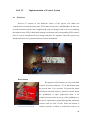
Unit IV
4.1
Implementation of Control System
Hardware
Process of creation of the hardware aspect of the project was rather not
complicated. It consisted of two parts, WCS (main control box) and BlackBox. In first case
as both electronic boards came completed the only two things I had to do were soldering
the headers to the WiFly shield and creating reset button with corresponding LED, connect
pins for servos and photocell and casing with place for antenna. Until the project was
finished all ideas were prepared and tested on the breadboard.
Figure 15. Prototype version of control system based on breadboard
Reset button
The purpose of this button is to reset to default
wireless network parameters. To do that button must
be pressed from 3 to 6 seconds. To protect the board
pull-down 10k ohm resistor is placed in circuit. When
the pushbutton is open (unpressed) there is no
connection between the two legs of the pushbutton, so
the pin is connected to ground (through the pull-down
resistor) and we read a LOW. When the button is
Figure 16. Prototyping part of the WiFly
shield seen from the bottom
closed (pressed), it makes a connection between its
26
two legs, connection pin to voltage, so that we read a HIGH. For the convenience of the
user additional LED is placed into the circuit. When button is closed LED starts to blink. In
addition, when reset takes place LED blinks 3 to 6 times fast in a row to confirm.
Servomotor pins
To control servos simple connection consisting of three cables is needed. Ground,
power and control signal. I have placed two sets of
pins directly to control two servos. With simple
modification of software more servomotors can be
connected to the board.
Photocell pins
In order to connect photocell voltage divider
is needed. In this case 10k resistor was used.
Figure 17. Sockets of the BlackBox
To cope with the high sensitivity of the
photocell the concept of hysteresis was used. Based on experimental deduction the delay of
±5 point is set.
Main chasing
It was designed to protect electronic
parts from light damage that might appear
during transport or presentation. Two 3mm
thick transparent plexi plates for top and bottom
makes it very useful in educational application.
In top cover additional holes for led, headers,
servo/photocell pins and wifi antenna connector
were cut.
Figure 18. Chasing of the Control System
BlackBox photocell
To present example application photocell was needed. A
photocell is a type of resistor that reacts with the light. When it is
strike by light, cell allows current to flow more freely. However, in
Figure 19. BlackBox’es
photocell
27
the absence of light, its resistance
increases dramatically. In this case due to
the analog input photocell is connected to
its range is between 0 and 1023.
BlackBox blinds
To set light intensity simple single
blind
controlled
by
servomotor
is
Figure 20. Concept of the hysteresis in application to photocell
adopted. As we can see on the photograph
round blind half transparent half black
allows us to use 180˚ control range of the
servomotor.
BlackBox chasing
Housing itself is built in the same
Figure 21. Shutter mechanism
manner as main chasing. 3mm black plexi
plates with no light permeability used to construct bottom and walls of the box prevent
photocell from receiving any signal when blind is closed. The top cover of the box is made
of the transparent plexi painted black without semicircle in the middle. It is attached by
four screws, one in each corner.
Inside, in the corner, there
are two sets of sockets. Double pin
to connect the photocell and triple
to connect the servomotor. As
photocell is symmetrical it does not
matter how we connect the plug.
However
marked
servomotor
with
pins
are
appropriate
colors(black for ground, red for
positive supply and yellow for
control
signal)
to
connect
it
properly. It is important to go by
colors
because
connecting
Figure 22. BlackBox without the top cover
28
servomotor any other way will damage it.
To place servomotor with blind on it I have used a stand based on three screws with
spring bumpers. When the adjustment of height is needed we just screw on or off the
overlays. The springs persist stand from falling down while overlays determine the
maximal height. Underneath the stand the photocell is placed.
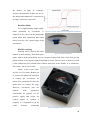
Power supply
To power up control system with two servomotors USB computer port is not
enough. Only one servomotor can be used In this case two possible power supply methods
has been used.
First one is stationary switching power supply from Linksys.
Figure 23. Linksys power supply
Model : PSM11R-050
Input : 100-240V0.3A 50-60Hz
Output : +5V 2A
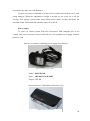
And second one is USB battery from Power.Guy
Figure 24. Power.Guy battery
29
Model : Portable Power Pack D.2200.
Input : 5V Micro USB
Output : 5-5.5V – 700mA
Battery Type : 3.7V – 2200mAh
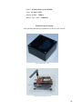
Finished Control System
After finishing hardware preparations two boxes were created.
Figure 26. BlackBox - final
Figure 25. Control System - final
30
4.2
Software
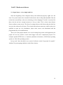
The software prepared for the project consists of two parts. First one is the
application written for control board. The second is the software written in Embarcadero
Delphi 2009, pc win32 application that allows us to communicate with control system over
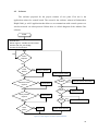
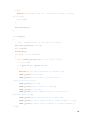
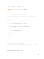
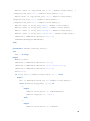
wireless network via telnet protocol. Below there is a block diagram of the Arduino Uno
software.
START
- load libraries
- define regisers, variables and structures
- initialize I/O, SPI_Uart bridge
- connect to the network
NO
Client
Request
YES
Hard
Restet
YES
Reset to default
Clear register buffer
NO
NO
YES
Photocell value
request
Send value
YES
TELNET
Execute Telnet command
NO
NO
POST
Servo position
request
YES
Send value
Auto
photo
YES
Adjust
Move servo
NO
GET
NO
YES
YES
Send data over HTML
Check client request
NO
Figure 27. Block diagram of Control System software
31
ARDUINO
It all began with the installation of the Arduino board on my PC. As it is written in
“getting started”11 guide all went smooth and easy. The only thing I had do to after
downloading drivers and software was to navigate to the “ArduinoUNO.ini” file located in
drivers folder to install proper drivers.
In the next step I had to familiarize myself with
the programming environment supplied with Arduino
board. Arduino alpha v.0.0.2.2 is an open project
written, debugged and supported by Massimo Banzi,
David Caurtielles, Tom Igoe, Gianluca Martino and
David Mellis. It is based on “Processing” by Casey
Reas and Ben Fry. As whole language is mostly based
Figure 28. Arduino alpha v.0.0.2.2
on C++ this process was limited to recognize syntax
distinctive for Arduino board. “Learning” section of
Arduino project website where essential code examples
are placed appeared to be very useful in understanding
of how does it work.
After few days of playing with Arduino the time
for WiFly shield has come. Everything went smoother
as in this case bigger technical support is provided.
The last step was application of the BlackBox. To
do this the handling of analog input as well as two
Figure 29. Arduino alpha v.0.0.2.2 GUI
modes of work, manual (manual control over servos) and automatic (setting light intensity
without controlling over the servo) were needed.
Let us now focus on source code written for Arduino Uno board. Whole syntax
consists of main 4 parts. To avoid huge amount of text I will only describe more complex
and essential functions. Full listing can be found in appendix A12
The first thing are declarations. In this part we declare all the libraries, variables,
structures and registers we will need.
11
12
http://arduino.cc/en/Guide/Windows
See page 61
32
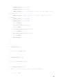
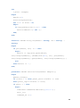
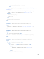
Second one is “viod setup()” function. This one is activated only once, at the start of
the board.
Third one is “void loop()” function which is call over and over again by the Arduino
itself. This is the place for our main program.
And the fourth one are all the other functions we need for our application to work.
All of them are called out in void loop() or other nested functions.
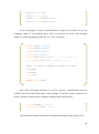
Shortened applications listing:
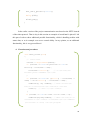
1. Declarations
To be able to use all procedures, functions, pins or properties we need to declare
some of them before the main part of the software. Following declarations are present in
the code:
-
External libraries :
o string.h – responsible for strings commands
o servo.h – set of commands controlling servomechanisms
o EEPROM.h – allows us to store data in 512 bytes of EEPROM memory
where values are stored when the board is turned off.
-
SC16IS750 register definitions
-
SPI pin definitions
-
Global variables :
o Powercell
o Servo
o Reset
o Wifi default parameters
-
SC16IS750 communication parameters and structure
2. void setup()
In this section steps are taken for the software to initialize on the very first start of
the control board.
33
myservo.attach(9);
myservo1.attach(8);
myservo.write(myservo_pos);
myservo1.write(myservo_pos);
At the beginning to control servomechanism it needs to be defined. To do this
command “attach” is used. Digital pins 8 and 9 are reserved for servos. After defining
output we set the beginning position at 0˚ by “write” command.
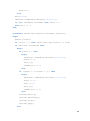
pinMode(MOSI, OUTPUT);
pinMode(MISO, INPUT);
pinMode(SCK,OUTPUT);
pinMode(CS,OUTPUT);
pinMode(photoPin, INPUT); // setting input pin
digitalWrite(CS,HIGH); //disable device
SPCR = (1<<SPE)|(1<<MSTR)|(1<<SPR1)|(1<<SPR0);
clr=SPSR;
clr=SPDR;
delay(10);
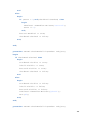
Serial.begin(9600);
SPI (Serial Peripheral Interface) is used to provide communication between
Arduino Uno board and WiFly shield. After defining SC16IS750 register definitions we
need to initialize Arduino pins over which communication will take place.
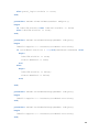
pinMode(ledPin, OUTPUT);
digitalWrite(inPin, HIGH);
Next are the pins that are used when reset button and supervising LED are used.
34
if(SPI_Uart_Init()) //Test SC16IS750 communication
{
Serial.println("Bridge initialized successfully!");
}
else{
Serial.println("Could not initialize bridge,
locking up.\n\r");
while(1);
}
autoconnect();
At the end of the setup section we check if the SPI-to-UART bridge is initialized
successfully (SPI_Uart_Init()) and afterwards if wireless connection with the predefined
configuration is set up properly(autoconnect()).
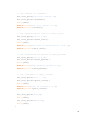
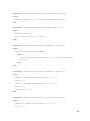
3. void loop()
SPI_Uart_println("exit");
delay(500);
Flush_RX();
…
while(!Have_Client());
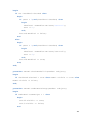
Void loop() is the section of the software that, as its name suggests, repeats over
and over again. This is the main part from which all external functions and procedures are
being called. For safety issues, just in case, at the the beginning we exit “command mode”
of the WiFly shield by sending command “exit” via SPI_Uart_println function and clear all
the data from receiving register. After that we simply wait for a client to appear.
35
if ((get == 1)||(post == 1))
{
Serial.println("\n\rConnection opened.");
HTML_print("<html>");
HTML_print("<title>Test of servo motor
controller</title>");
HTML_print("<h1>");
HTML_print("Servo controll TEST");
HTML_print("</h1>");
HTML_print("<form name=\"input\" action=\"/\"
method=\"post\">");
HTML_print("New Positon(range 0-180):");
HTML_print("<input type=\"text\" name=\"%poh\"
/>");
HTML_print("<input type=\"submit\"
value=\"Submit\" />");
HTML_print("</form>");
HTML_print("</br> ");
HTML_print("this is example of use of the HTML, as
we can see ");
HTML_print("simple status or control website can
be stored");
HTML_print(" inside");
HTML_print("</html>");
delay(500);
SPI_Uart_print("$$$");
delay(500);
SPI_Uart_println("close");
delay(1000);
36
SPI_Uart_println("exit");
delay(500);
Flush_RX();
}
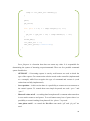
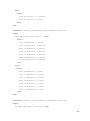
In the earlier version of the project communication was based on the HTTP instead
of the telnet protocol. That is why in this section an example of stored html is placed. I left
this part of code to show additional possible functionality, which is handling website with
status data, or as in example even servo control ability. In my opinion, as an additional
functionality, this is very powerful tool.
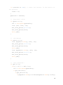
4. Functions and procedures
char Have_Client(void)
{
//
hard reset
current = digitalRead(inPin);
if (current == HIGH && previous == LOW &&
millis()- firstTime > 200){
firstTime = millis();
// if the buttons
becomes press remember the time
}
if (current == HIGH && ((millis() - firstTime) %
1000) < 20 && millis() - firstTime > 500){
ledblink(1, 50, ledPin); // Each second the
button is held blink the indicator led and
count++;
// and 1 to the counter
}
if (current == LOW && count >=3 && count < 6){
ledblink(10,200,ledPin); // When the button is
released if the counter is between the two numbers
(3-6 blinks or secs) run the program
37
// Exit command mode if we haven't already
SPI_Uart_println("");
SPI_Uart_println("exit");
delay(500);
// Enter command mode
SPI_Uart_print("$$$");
delay(500);
SPI_Uart_print("set opt password 0");
delay(500);
Serial.print("Set wlan password to none");
// Set ssid
SPI_Uart_print("set wlan ssid ");
SPI_Uart_println(ssid);
delay(500);
Serial.print("Set wlan ssid to ");
Serial.println(ssid);
// Set channel to <channel>
SPI_Uart_print("set wlan channel ");
SPI_Uart_println(channel);
delay(500);
Serial.print("Set wlan channel to ");
Serial.println(channel);
// Set authentication level to <auth_level>
SPI_Uart_print("set w a ");
SPI_Uart_println(auth_level);
delay(500);
Serial.print("Set wlan to authorization level
");
Serial.println(auth_level);
// Set authentication phrase to <auth_phrase>
SPI_Uart_print("set w p ");
SPI_Uart_println(auth_phrase);
delay(500);
38
Serial.print("Set security phrase to ");
Serial.println(auth_phrase);
// Set localport to <port_listen>
SPI_Uart_print("set i l ");
SPI_Uart_println(port_listen);
delay(500);
Serial.print("Set IP localport to ");
Serial.println(port_listen);
SPI_Uart_print("save");
delay(500);
SPI_Uart_println("exit");
delay(500);
}
if (current == LOW){ // reset the counter if the
button is not pressed
count = 0;
}
previous = current;
// photocell value
if (photo == 1){
val = analogRead(photoPin);
itoa (val, val2, 10);
SPI_Uart_print("photo=");
SPI_Uart_print(val2);
delay(90);
}
// servomotor
if (servo == 1){
itoa (myservo.read(), val2, 10);
SPI_Uart_print("servo=");
SPI_Uart_print(val2);
delay(90);
39
itoa (myservo1.read(), val2, 10);
SPI_Uart_print("servo1=");
SPI_Uart_print(val2);
delay(90);
}
// auto photocell
if (ph == 1){
for(i = 0; i < 180; i++){
val = analogRead(photoPin);
if(ph_val!=val){
if(ph_val<val-5){
if((myservo.read()1<=181)&&(myservo.read()-1>=0)){
myservo.write(myservo.read()-1);
}
}
if(ph_val>val+5){
if((myservo.read()+1<=180)&&(myservo.read()+1>=0)){
myservo.write(myservo.read()+1);
}
}
delay(10);
}
}
}
if(SPI_Uart_ReadByte(LSR) & 0x01){
Serial.println("Client request...");
Parse_Request(); // Check if request is a
GET/POST
Flush_RX();
return 1;
}
40
else{
return 0;
}
}
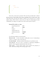
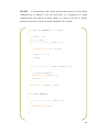
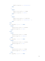
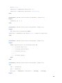
Above Have_Client(void) is presented. This is the first procedure that is called in
the loop section to check whether client requests something from our control system. After
being called status of the hard reset button is checked. If it is pressed for 4 to 6 seconds
default setting to WiFly shield are written and saved. Otherwise nothing happens besides
LED blinking. For changes to be applied, reset of the control system is required.
Default WiFly shield reset values
Connection password :
none
SSID :
dlink
Channel :
6
Authentication level :
4
Authentication phrase :
dlink007
Port :
2000
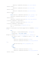
Next following conditions are being checked.
-
Photocell value – if value of the global variable photo is set to 1 it means that pc
software is waiting for values of the photocell,
-
Servomechanisms – similarly to photocell data about servos position are send,
-
Auto photocell – this part of code is responsible for adjusting the BlackBox‟es
shutter to achieve appropriate light intensity inside of the box.
-
Client request – if client requests another action procedure Parse_Request() is
called. Afterwards cleaning of the incoming register occurs.
41
void Parse_Request(void)
{
int j = 0, k = 0;
String temp = "";
inc_data_all = "";
post = 0;
get = 0;
while(j < 4000)
{
if((SPI_Uart_ReadByte(LSR) & 0x01))
{
incoming_data = SPI_Uart_ReadByte(RHR);
Serial.print(incoming_data,BYTE);
if ((inc_data_all.indexOf("POST") != 1)&&(k==0))
{
post = 1;
get = 0;
k = 1;
}
if ((inc_data_all.indexOf("GET") != 1)&&(k==0))
{
post = 0;
get = 1;
k = 1;
}
if (inc_data_all.indexOf("%") != -1)
{
inc_data_all = "";
}
else
{
inc_data_all += incoming_data;
}
42
}
else
{
j++;
}
}
//
if (post == 1) // check if incoming package is
POST
//
//
{
inc_data_all.trim();
//
//
if (inc_data_all.indexOf("poh=") != -1) //
new position for servo
//
//
{
if (inc_data_all.indexOf("&",
inc_data_all.indexOf("poh=")+4) == -1)
//
{
//
k = inc_data_all.length()+1;
//
Serial.println("k=length+1: ");
//
Serial.println(k);
//
}
//
else
//
{
//
k = inc_data_all.indexOf("&",
inc_data_all.indexOf("poh=")+4)+1;
//
Serial.println("k=indexOf: ");
//
Serial.println(inc_data_all.indexOf("poh=")+1);
//
}
//
for (j = inc_data_all.indexOf("poh=")+4; j
< k; j++)
//
{
//
//
temp += inc_data_all.charAt(j);
}
43
//
myservo_pos = 0;
//
//convertion ascii to integer
//
for (int i = 0; i < temp.length()-1; i++)
//
{
//
myservo_pos = (myservo_pos * 10) +
temp.charAt(i) - '0';
//
}
//
//
Serial.println(myservo_pos);
//
myservo.write(myservo_pos);
//
}
//
SPI_Uart_print("$$$");
//
delay(500);
//
SPI_Uart_println("close");
//
delay(1000);
//
SPI_Uart_println("exit");
//
delay(500);
//
Flush_RX();
//
inc_data_all = "";
//
}
if (inc_data_all.indexOf("pos=") != -1) // new
position for servo from telnet
{
temp = "";
for (j = inc_data_all.indexOf("pos=")+4; j <
inc_data_all.length()-1; j++)
{
temp += inc_data_all.charAt(j);
}
myservo_pos = 0;
//convertion ascii to integer
for (int i = 0; i < temp.length()-1; i++)
{
myservo_pos = (myservo_pos * 10) +
44
temp.charAt(i) - '0';
}
Serial.println(myservo_pos);
myservo.write(myservo_pos);
SPI_Uart_print("OK");
Flush_RX();
inc_data_all = "";
}
if (inc_data_all.indexOf("poz=") != -1) // new
position for servo from telnet
{
temp = "";
for (j = inc_data_all.indexOf("poz=")+4; j <
inc_data_all.length()-1; j++)
{
temp += inc_data_all.charAt(j);
}
myservo_pos = 0;
//convertion ascii to integer
for (int i = 0; i < temp.length()-1; i++)
{
myservo_pos = (myservo_pos * 10) +
temp.charAt(i) - '0';
}
Serial.println(myservo_pos);
myservo1.write(myservo_pos);
SPI_Uart_print("OK");
Flush_RX();
inc_data_all = "";
}
45
if (inc_data_all.indexOf("photo") != -1)
{
if (inc_data_all.indexOf("photo=1") != -1){
photo = 1;
}
else{
photo = 0;
}
inc_data_all = "";
SPI_Uart_print("command-OK");
}
if (inc_data_all.indexOf("servo=") != -1)
{
if (inc_data_all.indexOf("servo=1") != -1){
servo = 1;
}
else{
servo = 0;
}
inc_data_all = "";
SPI_Uart_print("command-OK");
}
if (inc_data_all.indexOf("ph=off") != -1){
ph=0;
Flush_RX();
inc_data_all = "";
SPI_Uart_print("command-OK");
}
if (inc_data_all.indexOf("ph=") != -1)
{
temp = "";
for (j = inc_data_all.indexOf("poz=")+4; j <
inc_data_all.length()-1; j++)
{
46
temp += inc_data_all.charAt(j);
}
ph=1;
ph_val=0;
for (int i = 0; i < temp.length()-1; i++)
{
ph_val = (ph_val * 10) + temp.charAt(i) - '0';
}
Flush_RX();
inc_data_all = "";
SPI_Uart_print("command-OK");
}
}
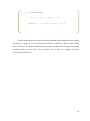
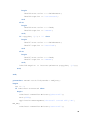
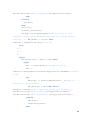
Parse_Request is a function that does not return any value. It is responsible for
determining the syntax of incoming request/command. There are few possible command
syntax listed below.
-
GET/POST – if incoming request is sent by web browser we need to check the
type of the request. Get returns main website stored on the controller (implemented
as a example) while Post recognize the type of command and execute it (code
written but not fully implemented).
-
Servo position – in this version there is a possibility to connect two servomotors to
the control system. To control them two simple keywords are used: “pos=” and
“poz=”.
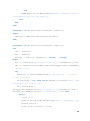
-
Photocell value on/off – as reading data from photocell is constant when turned on
it uses much resources and power. To avoid unnecessary lost of power there is a
possibility to control reading from photocell via “photo=” keyword.
-
Auto photo on/off – to control the BlackBox auto mode “ph” and “ph_val” are
used.
47
-
TELNET – to communicate with control system telnet protocol is used. When
command sent to Arduino is not one from above it is recognized as a telnet
command and send directly to WiFly shield. It is done to be able to change
properties of wireless connection stored within RN-131C module.
void Save_To_EEPROM(String data)
{
int start = 0;
byte c = 255;
for (int i = 0; i < 1023; i++)
{
if (EEPROM.read(i) == 255)
{
start = i + 1;
break;
}
}
for (int i = 0; i < data.length(); i++)
{
c = data.charAt(i);
EEPROM.write(start, c);
start++;
}
EEPROM.write(start , 255);
}
void Clear_EEPROM()
{
for (int i = 0 ; i < 1023 ; i++)
{
EEPROM.write(i,0);
}
}
48
void Read_EEPROM()
{
for (int i = 0; i < 1023 ; i++)
{
Serial.print(EEPROM.read(i), BYTE);
}
}
During designing process issue with saving data that will not disappear after cutting
out the power appeared. To solve this problem I have created set of functions that allows
us to save data to 1024 bytes of flash memory shared on Arduino Uno. Despite the fact that
in final version it is not used I have left this part of code as a support for future
developments of the code.
49
DELPHI (win32)
In the second stage the time for pc application has come. Delphi is the objectoriented programming language based on Pascal. Version I have used was the 2009
Professional trial that allows to test all means necessary for the project. Before the
beginning I have received permission from the official Embarcadero distributor in Poland
to use trial version in this project.
1. Operating Principle
WCC application has two tasks: one, to control servo and the BlackBox and
two, to manage WCS settings that allows to connect to the wireless network. To
achieve them we can not forget about appropriate level of security.
Operating principle is very simple. At the beginning user needs to log in. After
positive verification of the username and password application tries to connect
via telnet protocol with WCS (IP address is written in external setup.ini file). If
connection was successful, control and settings options are available.
2. Components
IdTelnet – responsible for handling telnet protocol.
MainMenu – simple menu creation.
Timer – controlling “on time” events in application.
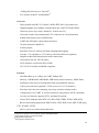
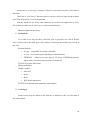
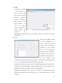
3. GUI (Graphical User Interface)
Graphical Interface is a standard one built
with components provided by Delphi.
Nothing extraordinary was adopted in this
matter. Simple menu with Login, Servo
and Settings pages is clear for the user as
befits engineering software design not to
Figure 30. WirelessControlClient GUI
please eye but to control determined
process.
50
4. Login
As simple as it sounds
to enter software we
need to log in. This
most basic protection
prevents
unwanted
people or software to
take control over our
client software. To
level
up
security
separate algorithm to
encode
login
password
and
Figure 31. WirelessControlClient Login screen
are
implemented. Both of them are stored inside “setup.ini” file next to the main
execute file.
5. Servo
Next page available inside
of
the
application
is
“Servo”. Here we are able to
control
both
servomotors
connected to the external
pins as well as photocell
connected inside BlackBox.
In every case two modes are
available: manual and auto.
Figure 32. WirelessControlClient servo administration screen
In
servo
manual
mode
servomotors will move by the wanted degree as told. When entering this mode
on “servo_1” photocell automatically goes into auto mode.
In photocell manual mode user can set searched light intensity inside the box.
System will try to adjust blind. If wanted, light intensity is out of possible scale,
appropriate message will appear inside of the application.
Additional functionality is the “advanced” check box. When checked, memo
with data both sent and received appears. It is quite useful when we check
dataflow.
51
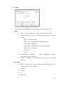
6. Settings
Figure 33. WirelessControlClient settings adminstration
screen
This is the part of the program were four groups of settings can be found.
Basic:
SSID – ssid of the network we want control system to connect
Authentication level – here we define authentication used in wireless
network
Open – No authentication
WEP-128 – open mode only, NOT shared mode
WPA1-PSK – TKIP only
Mixed PWA1 & WPA2-PSK – limited Aps support
WPA2-PSK – AES only
Not Used
Adhoc
Authentication
phrase/key
–
when
WEP/WPA
selected
key/passphrase must be defined
Channel – channel of the defined network, Set to 0 for auto
scanning.
Advanced:
DHPC – turning on/off server from the network, when turned off set
of additional setting is available
Netmask
Gateway
IP
Backup IP
52
DNS Address
DNS Name
DNS Backup
Connection Password – additional security measure. When set up no
one without it will be able to change control system settings.
Port – defines port to communicate
External Antenna – sets external/internal antenna available
Auto join – automatic joining defined network after power up.
Status:
Here basic status for connection and control system can be found(channel,
DNS, authentication, association and TCP).
Telnet:
For even more advanced setting telnet console is implemented. All available
command are written down in “WiFly GSX 802.11 b/g wireless LAN Module
User Manual and Command Reference13”
Application:
To change login or password that are required to enter client application enter
this page.
7. About
Short information about author and project.
8. Help
For the application to be more user-friendly I have applied hints system. When
having doubts about button, field or another functionality try to click question
mark on menu bar. When it changes to double question mark it means it is
active. Then simply target with cursor object and hint with description will
appear.
9. Reset
When pressed photocell value, auto photocell and servos positions turns off.
Application acts like
10. Status
This button allows us to connect/disconnect to the WCS after being logged to
the application.
13
http://www.sparkfun.com/datasheets/Wireless/WiFi/WiFlyGSX-um2.pdf
53
4.3
Observations
During many tests conducted in the process of projecting and creating Control
System I have noticed series of pros and cons. Some of them are to be revised and some
are not. In this testing report I will focus on issues significant in my opinion.
Lag
As expected in every wireless system visible lag occurs. In our case the time from
sending command from WCC software to receiving back confirmation of done task is
about 0.8 second. When we take into consideration that this data flows over WPA2-PSK
encrypted network it is not awfully long. To decrease this delay time we need to properly
optimize Arduino code.
Max servos
For the demonstration of the Control System I have implemented control over two
servomotors. In practice the only matters that limits number of servos are available pins
and power supply. In this case pins 10-13 are used by the WiFly shield to communicate
with Arduino over SPI. Second pin is used by the button and seventh by the LED. This
leaves us with total maximum amount of 6 servomechanisms. To extend this number
additional shield is required.
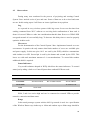
Status Indicators
Very useful solutions adopted in WiFly shield are the status indicators. To control
status just by taking a look over Control System three onboard LEDs are used.
Condition
PIO6 = RED
PIO5 = Yellow
Connected over TCP
ON Solid
Fast blink
Not Associated
Rx/Tx data transfer
No IP address
IP address OK
Slow blink
OFF
PIO4 = Green
Associated
PIO4, 5 and 6 are active high and can be connected to external LEDs to provide
network, connection and data status.
Range
In the tested prototype system wireless 802.11g network is used. As a specification
of the Wireless Router says indoor up to 100m and outdoor up to 400m range should be
54
achievable. As always those are the values from perfect conditions. In real life range did
not exceeded 100 meters outdoor in building area.
Influence of another networks
To test this issue, whole system was working in the area with four another wireless
networks. Despite this fact, no visible interference between the network was noticed.
Photocell accuracy (daylight, bulb, fluorescent lamp)
During the test I have noticed that the type of light source from which we are trying
to measure light intensity has a great influence on the results. When we use bulb the light
flickers with such an intensity that despite constant distance and light intensity the reading
form photocell in extreme case was dropping and rising in range of ±15 points. Fluorescent
lamp effected in reading variations at level of maximal 5 points when daylight reading was
nearly constant. To overcome this effect, but not at the big cost of accuracy, the delay at
level of ±5 point to servo reaction has been added.
Speed control
As this project is based on open source platform many beta or hobby libraries are
available. One of those is VarSpeedServo library which allows us to easily control speed of
the connected servos. Due to the problems with application that appeared when project was
created I have decided not to use this library. Considering rapid development of
VarSpeedServo library it will be very valuable asset in future modifications of WCS.
Electric discharge
Another advantage that is really important in application of this control system is
safety from electric discharges. When power supplied from source separate from the power
network there is no risk in electric discharges from the grid. This allows us to omit
expensive devices which task is to protect from power network influence.
Reset
Two reset button are placed on the control system. One(silver/gold) acts like
turning on and off again. It is meant to be use when WCS hangs up. The other one(black)
is designed to reset to defaults settings of the wireless module. Both of them appears to be
working without any problems.
Antenna
To expand range of the device external antenna is provided. In prototype standard
2dBi D-link antenna is used. As standard connector is used there is possibility to change
antenna to one with greater range.
Hanging up
55
Unfortunately prototype device I have prepared is not flawless. During tests I have
noticed specific situations when WCS hangs up and needs reset.
The main case is connected with power supply. When power is insufficient even for
a brief of time communication between computer software and control system becomes
impossible.
Another possibility of hanging up is caused, in my opinion, by errors in WCS surce
code. Despite my very best efforts, mistakes are human thing.
Yet to implement
As we can see in the overview of the WiFly shield there are many possibilities of
expanding our Control system. In my opinion, the most valuable is the power management.
When using this device as a portable power consumption becomes an issue. Thanks to
sleep mode, wake on UART and other available functions, we can significantly extend
work time on battery.
Another not fully implemented feature is the HTTP server. As an example, simple
website is stored inside of the Control System. It gives us opportunity to create separate
interface to manage certain settings or just show status data. Real time clock within WiFly
allows us to use time stamping. Thanks to this login/session algorithms can be
implemented to rise security level of data over HTTP.
To allow being up-to-date with firmware, there is a possibility to implement overthe-air upgrade with use of the ftp. When thinking about final product this is a worthwhile
solution.
Of course there are plenty not implemented setting from the level of WCC
software. We can connect to the Adhoc networks, manage time or UART parameters or
use UDP protocol instead of TPC/IP. With all of these possibilities really advanced
projects are at out fingertips. The only border is our imagination.
56
Conclusion
To sum up I believe that solution I have implemented to resolve the problem of the
wireless control system of the servomotor have met the expectations of the project.
Furthermore huge potentiality of future expansions leaves solution open for development
in many different subjects. For example in more complicated situations to improve speed
of operations, without any problem, golden section search algorithm can be implemented.
Various new sensors like accelerometer, pressure, temperature, tilt, move or hallotron can
be connected. Many communication protocols can be implemented (xbee, gsm, gps, etc.)
or when talking about servomotors, bigger project that need even up to 48 separately
controlled servomotors are possible to handle.
57
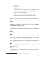
Bibliography
Literature
1. Massimo Banzi, Getting Started with Arduino, O‟Reilly, First Edition, October
2008,
2. Tom Igoe, Making Things Talk, O‟Reilly, First Edition, September 2007
3. Joshua Noble, Programming Interactivity, O‟Reilly, First Edition, July 2009
4. RovingNetworks, WiFly GSX 802.11 b/g wireless LAN Modules User Manual and
Command Reference, Version 2.21, 11 July 2010
Web pages:
1. http://www.engineersgarage.com/articles/servo-motor
2. http://www.sparkfun.com/products/9367
3. http://forum.sparkfun.com/
4. http://arduino.cc/
5. http://arduino.cc/forum/
6. http://arduino.cc/playground/
7. http://standards.ieee.org/about/get/802/802.11.html
8. http://www.ieee802.org/11/
Articles:
1. CTylor,
WiFly
Wireless
SpeakJet
Server,
04
March
2010,
http://www.sparkfun.com/tutorials/158
58
Census figures
Figure 1. Construction of the servomotor .............................................................................. 6
Figure 2. Pulse servo control ................................................................................................. 7
Figure 3. Servo motor system schematics ............................................................................. 8
Figure 4. Arduino Uno – Front ............................................................................................ 12
Figure 5. Arduino Uno – Back ............................................................................................ 13
Figure 6. WiFly SparkFun Arduino shield
[source:http://www.sparkfun.com/products/9954] .............................................................. 16
Figure 7. CodeGear Delphi 2009 by Embarcadero Technologies. ...................................... 18
Figure 8. Delphi 2009 GUI .................................................................................................. 18
Figure 9. Schematic diagram of the control system for servomotor with application of
wireless network .................................................................................................................. 19
Figure 10. D-Link DSL-G684T ADSL2+ 54M Wireless Router w/ 4 Port 10/100 Switch 20
Figure 11. General Specification ......................................................................................... 20
Figure 12. Physical and Environmental Specification......................................................... 21
Figure 13. Wireless Specification ........................................................................................ 21
Figure 14. Hextronik HXT900 ............................................................................................ 22
Figure 15. Prototype version of control system based on breadboard................................. 26
Figure 16. Prototyping part of the WiFly shield seen from the bottom............................... 26
Figure 17. Sockets of the BlackBox .................................................................................... 27
Figure 18. Chasing of the Control System .......................................................................... 27
Figure 19. BlackBox‟es photocell ....................................................................................... 27
Figure 20. Concept of the hysteresis in application to photocell........................................ 28
Figure 21. Shutter mechanism ............................................................................................. 28
Figure 22. BlackBox without the top cover ......................................................................... 28
Figure 23. Linksys power supply ........................................................................................ 29
Figure 24. Power.Guy battery.............................................................................................. 29
Figure 25. Control System - final ........................................................................................ 30
Figure 26. BlackBox - final ................................................................................................. 30
Figure 27. Block diagram of Control System software ....................................................... 31
Figure 28. Arduino alpha v.0.0.2.2 GUI.............................................................................. 32
Figure 29. Arduino alpha v.0.0.2.2 ...................................................................................... 32
Figure 30. WirelessControlClient GUI................................................................................ 50
59
Figure 31. WirelessControlClient Login screen .................................................................. 51
Figure 32. WirelessControlClient servo administration screen ........................................... 51
Figure 33. WirelessControlClient settings adminstration screen ........................................ 52
Figure 34. Arduino Uno schematics .................................................................................... 62
Figure 35. WiFly shield from SparkFun .............................................................................. 63
60
Appendixes
Appendix A – Arduino Uno Schematics ............................................................................... 62
Appendix B – WiFly SparkFun Schematics ......................................................................... 62
Appendix C – Arduino Source Code .................................................................................... 64
Appendix D – Delphi Source Code ........................................................................................ 87
Appendix E – Project on CD ............................................................................................... 118
61
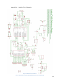
Appendix A – Arduino Uno Schematics
Figure 34. Arduino Uno schematics
[source: http://arduino.cc/en/uploads/Main/arduino-uno-schematic.pdf]
62
Appendix B – WiFly SparkFun Schematics
Figure 35. WiFly shield from SparkFun
[source: http://arduino.cc/en/uploads/Main/arduino-uno-schematic.pdf]
63
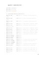
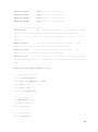
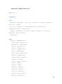
Appendix C – Arduino Source Code
#include <string.h>
#include <Servo.h>
#include <EEPROM.h>
//
SC16IS750 Register Definitions
#define THR
0x00 << 3 // Transmit Holding Register
(THR)
#define RHR
0x00 << 3 // Receive Holding Register
(RHR)
#define IER
0x01 << 3 // Interrupt Enable Register
(IER)
#define FCR
0x02 << 3 // FIFO Control Register (FCR)
#define IIR
0x02 << 3 // Interrupt Identification
Register (IIR)
#define LCR
0x03 << 3 // Line Control Register (LCR)
#define MCR
0x04 << 3 // Modem Control Register (MCR)
#define LSR
0x05 << 3 // Line Status Register (LSR)
#define MSR
0x06 << 3 // Modem Status Register (MSR)
#define SPR
0x07 << 3 // Scratchpad Register (SPR)
#define TXFIFO
0x08 << 3
#define RXFIFO
0x09 << 3
#define DLAB
0x80 << 3
#define IODIR
0x0A << 3 // I/O pin Direction Register
#define IOSTATE
0x0B << 3 // I/O pin States Register
#define IOINTMSK
0x0C << 3
#define IOCTRL
0x0E << 3 // I/O pins Control Register
#define EFCR
0x0F << 3 // Extra Features Register
#define DLL
0x00 << 3 // divisor latch LSB (DLL)[4]
#define DLM
0x01 << 3 // divisor latch MSB (DLH)[4]
#define EFR
0x02 << 3 // Enhanced Feature Register
(EFR)[5]
64
#define XON1
0x04 << 3 // Xon1 word[5]
#define XON2
0x05 << 3 // Xon2 word
#define XOFF1
0x06 << 3 // Xoff1 word
#define XOFF2
0x07 << 3 // Xoff2 word
//
SPI pin definitions
#define CS
10 //Slave Select pin - allocated on each
device which the master can use to enable and disable
specific devices and avoid false transmissions due to line
noise.
#define MOSI
11 //Master Out Slave In (MOSI) - The
Master line for sending data to the peripherals
#define MISO
12 //Master In Slave Out (MISO) - The
Slave line for sending data to the master,
#define SCK
13 //Serial Clock (SCK) - The clock pulses
which synchronize data transmission generated by the master,
and
#define ASSOCIATE_TIMEOUT 5000
//
Global variables
char incoming_data;
char TX_Fifo_Address = THR;
char get = 0;
char post = 0;
String inc_data_all;
//
Photocell
int photoPin = 0;
int val = 0;
char val2[5] ;
//
Servomotor
Servo myservo;
65
Servo myservo1;
int myservo_pos = 0;
int i = 0;
int j = 0;
int k = 0;
int user = 0;
char clr = 0;
char polling = 0;
int servo = 0;
int photo = 0;
//
Auto photocell
int ph = 0;
int ph_val = 0;
//
Hard reset
int inPin = 2;
int ledPin = 7;
int current;
int count;
byte previous = LOW;
unsigned long firstTime;
//
SC16IS750 communication parameters
struct SPI_UART_cfg
{
char DivL,DivM,DataFormat,Flow;
};
struct SPI_UART_cfg SPI_Uart_config = {
0x60,0x00,0x03,0x10};
//
Wifi default parameters
66
char auth_level[] = "4";
char auth_phrase[] = "dlink007";
char port_listen[] = "2000";
char channel[] = "6";
char ssid[] = "dlink";
void setup()
{
//
servo initialization
myservo.attach(9);
myservo1.attach(8);
myservo.write(myservo_pos);
myservo1.write(myservo_pos);
//
SPI pin initialization
pinMode(MOSI, OUTPUT);
pinMode(MISO, INPUT);
pinMode(SCK,OUTPUT);
pinMode(CS,OUTPUT);
pinMode(photoPin, INPUT); // setting input pin
digitalWrite(CS,HIGH); // disable device
SPCR = (1<<SPE)|(1<<MSTR)|(1<<SPR1)|(1<<SPR0);
clr=SPSR;
clr=SPDR;
delay(10);
Serial.begin(9600);
//
hard reset
pinMode(ledPin, OUTPUT);
digitalWrite(inPin, HIGH);
Serial.println("\n\r\n\rWiFly Shield Terminal Routine");
if(SPI_Uart_Init()){ // Test SC16IS750 communication
Serial.println("Bridge initialized successfully!");
}
67
else{
Serial.println("Could not initialize bridge, locking
up.\n\r");
while(1);
}
autoconnect();
}
void loop()
{
// Exit command mode if we haven't already
SPI_Uart_println("exit");
delay(500);
Flush_RX();
while(1) // If GET/POST
{
while(!Have_Client()); // Wait for client
// Sent HTML
if ((get == 1)||(post == 1))
{
Serial.println("\n\rConnection opened.");
HTML_print("<html>");
HTML_print("<title>Test of servo motor
controller</title>");
HTML_print("<h1>");
HTML_print("Servo controll TEST");
HTML_print("</h1>");
HTML_print("<form name=\"input\" action=\"/\"
method=\"post\">");
HTML_print("New Positon(range 0-180):");
HTML_print("<input type=\"text\" name=\"%poh\" />");
HTML_print("<input type=\"submit\" value=\"Submit\"
/>");
68
HTML_print("</form>");
HTML_print("</br> ");
HTML_print("this is example of use of the HTML, as we
can see ");
HTML_print("simple status or control website can be
stored");
HTML_print(" inside");
HTML_print("</html>");
delay(500);
SPI_Uart_print("$$$");
delay(500);
SPI_Uart_println("close");
delay(1000);
SPI_Uart_println("exit");
delay(500);
Flush_RX();
}
}
}
void select(void)
{
digitalWrite(CS,LOW);
}
void deselect(void)
{
digitalWrite(CS,HIGH);
}
char Have_Client(void)
// Wait until we receive data (client request)
{
//
hard reset
69
current = digitalRead(inPin);
if (current == HIGH && previous == LOW && millis()firstTime > 200){
firstTime = millis();
// if the buttons becomes press
remember the time
}
if (current == HIGH && ((millis() - firstTime) % 1000) < 20
&& millis() - firstTime > 500){
ledblink(1, 50, ledPin); // Each second the button is
held blink the indicator led and
count++;
// and 1 to the counter
}
if (current == LOW && count >=3 && count < 6){
ledblink(10,200,ledPin); // When the button is released
if the counter is between the two numbers (3-6 blinks or
secs) run the program
// Exit command mode if we haven't already
SPI_Uart_println("");
SPI_Uart_println("exit");
delay(500);
// Enter command mode
SPI_Uart_print("$$$");
delay(500);
SPI_Uart_print("set opt password 0");
delay(500);
Serial.print("Set wlan password to none");
// Set ssid
SPI_Uart_print("set wlan ssid ");
SPI_Uart_println(ssid);
delay(500);
Serial.print("Set wlan ssid to ");
Serial.println(ssid);
70
// Set channel to <channel>
SPI_Uart_print("set wlan channel ");
SPI_Uart_println(channel);
delay(500);
Serial.print("Set wlan channel to ");
Serial.println(channel);
// Set authentication level to <auth_level>
SPI_Uart_print("set w a ");
SPI_Uart_println(auth_level);
delay(500);
Serial.print("Set wlan to authorization level ");
Serial.println(auth_level);
// Set authentication phrase to <auth_phrase>
SPI_Uart_print("set w p ");
SPI_Uart_println(auth_phrase);
delay(500);
Serial.print("Set security phrase to ");
Serial.println(auth_phrase);
// Set localport to <port_listen>
SPI_Uart_print("set i l ");
SPI_Uart_println(port_listen);
delay(500);
Serial.print("Set IP localport to ");
Serial.println(port_listen);
SPI_Uart_print("save");
delay(500);
SPI_Uart_println("exit");
delay(500);
}
71
if (current == LOW){ // reset the counter if the button is
not pressed
count = 0;
}
previous = current;
//
photocell value
if (photo == 1){
val = analogRead(photoPin);
itoa (val, val2, 10);
SPI_Uart_print("photo=");
SPI_Uart_print(val2);
delay(90);
}
//
servomotor
if (servo == 1){
itoa (myservo.read(), val2, 10);
SPI_Uart_print("servo=");
SPI_Uart_print(val2);
delay(90);
itoa (myservo1.read(), val2, 10);
SPI_Uart_print("servo1=");
SPI_Uart_print(val2);
delay(90);
}
//
auto photocell
if (ph == 1){
for(i = 0; i < 180; i++){
val = analogRead(photoPin);
if(ph_val!=val){
if(ph_val<val-5){
if((myservo.read()-1<=181)&&(myservo.read()-1>=0)){
72
myservo.write(myservo.read()-1);
}
}
if(ph_val>val+5){
if((myservo.read()+1<=180)&&(myservo.read()+1>=0)){
myservo.write(myservo.read()+1);
}
}
delay(10);
}
}
}
if(SPI_Uart_ReadByte(LSR) & 0x01){
Serial.println("Client request...");
Parse_Request(); // Check if request is a GET/POST
Flush_RX();
return 1;
}
else{
return 0;
}
}
char SPI_Uart_Init(void)
// Initialize SC16IS750
{
char data = 0;
SPI_Uart_WriteByte(LCR,0x80); // 0x80 to program baudrate
SPI_Uart_WriteByte(DLL,SPI_Uart_config.DivL); //0x50 = 9600
with Xtal = 12.288MHz
SPI_Uart_WriteByte(DLM,SPI_Uart_config.DivM);
73
SPI_Uart_WriteByte(LCR, 0xBF); // access EFR register
SPI_Uart_WriteByte(EFR, SPI_Uart_config.Flow); // enable
enhanced registers
SPI_Uart_WriteByte(LCR, SPI_Uart_config.DataFormat); // 8
data bit, 1 stop bit, no parity
SPI_Uart_WriteByte(FCR, 0x06); // reset TXFIFO, reset
RXFIFO, non FIFO mode
SPI_Uart_WriteByte(FCR, 0x01); // enable FIFO mode
// Perform read/write test to check if UART is working
SPI_Uart_WriteByte(SPR,'H');
data = SPI_Uart_ReadByte(SPR);
if(data == 'H'){
return 1;
}
else{
return 0;
}
}
void SPI_Uart_WriteByte(char address, char data)
// Write <data> to SC16IS750 register at <address>
{
long int length;
char senddata[2];
senddata[0] = address;
senddata[1] = data;
select();
length = SPI_Write(senddata, 2);
deselect();
74
}
long int SPI_Write(char* srcptr, long int length)
// Write string to SC16IS750
{
for(long int i = 0; i < length; i++)
{
spi_transfer(srcptr[i]);
}
return length;
}
void SPI_Uart_WriteArray(char *data, long int NumBytes)
// Write array to SC16IS750 THR
{
long int length;
select();
length = SPI_Write(&TX_Fifo_Address,1);
while(NumBytes > 16)
{
length = SPI_Write(data,16);
NumBytes -= 16;
data += 16;
}
length = SPI_Write(data,NumBytes);
deselect();
}
char SPI_Uart_ReadByte(char address)
// Read from SC16IS750 register at <address>
{
char data;
75
address = (address | 0x80);
select();
spi_transfer(address);
data = spi_transfer(0xFF);
deselect();
return data;
}
char autoconnect(void)
{
// Exit command mode if we haven't already
SPI_Uart_println("");
SPI_Uart_println("exit");
delay(500);
// Enter command mode
SPI_Uart_print("$$$");
delay(500);
// Reboot to get device into known state
Serial.println("Rebooting");
SPI_Uart_println("reboot");
delay(3000);
// Enter command mode
Serial.println("Entering command mode.");
SPI_Uart_print("$$$");
delay(500);
// Join wireless network <ssid>
Serial.print("Joining '");
Serial.print(ssid);
76
Serial.println("'");
delay(100);
Flush_RX();
delay(100);
SPI_Uart_print("join ");
SPI_Uart_println(ssid);
for(int p = 0; p < 40; p++)
{
Serial.print(".");
delay(ASSOCIATE_TIMEOUT/30);
}
Serial.println("");
Flush_RX();
// Check for association
SPI_Uart_println("show c");
if(Wait_On_Response_Char(13) != '0')
{
Serial.print("Failed to associate with '");
Serial.print(ssid);
Serial.println("'\n\rRetrying...");
Flush_RX();
autoconnect();
}
else
{
Serial.println("Associated!");
Flush_RX();
}
}
void Flush_RX(void)
// Flush characters from SC16IS750
77
{
int j = 0;
while(j < 4000)
{
if((SPI_Uart_ReadByte(LSR) & 0x01))
{
incoming_data = SPI_Uart_ReadByte(RHR);
}
else
{
j++;
}
}
}
void Parse_Request(void) // Parse request
{
int j = 0, k = 0;
String temp = "";
inc_data_all = "";
post = 0;
get = 0;
while(j < 4000)
{
if((SPI_Uart_ReadByte(LSR) & 0x01))
{
incoming_data = SPI_Uart_ReadByte(RHR);
Serial.print(incoming_data,BYTE);
if ((inc_data_all.indexOf("POST") != -1)&&(k==0))
{
post = 1;
get = 0;
k = 1;
}
78
if ((inc_data_all.indexOf("GET") != -1)&&(k==0))
{
post = 0;
get = 1;
k = 1;
}
if (inc_data_all.indexOf("%") != -1)
{
inc_data_all = "";
}
else
{
inc_data_all += incoming_data;
}
}
else
{
j++;
}
}
//
if (post == 1) // check if incoming package is POST
//
{
//
inc_data_all.trim();
//
//
if (inc_data_all.indexOf("poh=") != -1) // new position
for servo
//
//
{
if (inc_data_all.indexOf("&",
inc_data_all.indexOf("poh=")+4) == -1)
//
{
//
k = inc_data_all.length()+1;
//
Serial.println("k=length+1: ");
//
Serial.println(k);
79
//
}
//
else
//
{
//
k = inc_data_all.indexOf("&",
inc_data_all.indexOf("poh=")+4)+1;
//
Serial.println("k=indexOf: ");
//
Serial.println(inc_data_all.indexOf("poh=")+1);
//
}
//
for (j = inc_data_all.indexOf("poh=")+4; j < k; j++)
//
{
//
temp += inc_data_all.charAt(j);
//
}
//
//
myservo_pos = 0;
//
//convertion ascii to integer
//
for (int i = 0; i < temp.length()-1; i++)
//
{
//
myservo_pos = (myservo_pos * 10) + temp.charAt(i) -
'0';
//
}
//
//
Serial.println(myservo_pos);
//
myservo.write(myservo_pos);
//
}
//
SPI_Uart_print("$$$");
//
delay(500);
//
SPI_Uart_println("close");
//
delay(1000);
//
SPI_Uart_println("exit");
//
delay(500);
//
Flush_RX();
//
inc_data_all = "";
//
}
80
if (inc_data_all.indexOf("pos=") != -1) // new position for
servo from telnet
{
temp = "";
for (j = inc_data_all.indexOf("pos=")+4; j <
inc_data_all.length()-1; j++)
{
temp += inc_data_all.charAt(j);
}
myservo_pos = 0;
//convertion ascii to integer
for (int i = 0; i < temp.length()-1; i++)
{
myservo_pos = (myservo_pos * 10) + temp.charAt(i) '0';
}
Serial.println(myservo_pos);
myservo.write(myservo_pos);
SPI_Uart_print("OK");
Flush_RX();
inc_data_all = "";
}
if (inc_data_all.indexOf("poz=") != -1) // new position for
servo from telnet
{
temp = "";
for (j = inc_data_all.indexOf("poz=")+4; j <
inc_data_all.length()-1; j++)
{
temp += inc_data_all.charAt(j);
81
}
myservo_pos = 0;
//convertion ascii to integer
for (int i = 0; i < temp.length()-1; i++)
{
myservo_pos = (myservo_pos * 10) + temp.charAt(i) '0';
}
Serial.println(myservo_pos);
myservo1.write(myservo_pos);
SPI_Uart_print("OK");
Flush_RX();
inc_data_all = "";
}
if (inc_data_all.indexOf("photo") != -1)
{
if (inc_data_all.indexOf("photo=1") != -1){
photo = 1;
}
else{
photo = 0;
}
inc_data_all = "";
SPI_Uart_print("command-OK");
}
if (inc_data_all.indexOf("servo=") != -1)
{
if (inc_data_all.indexOf("servo=1") != -1){
servo = 1;
}
82
else{
servo = 0;
}
inc_data_all = "";
SPI_Uart_print("command-OK");
}
if (inc_data_all.indexOf("ph=off") != -1){
ph=0;
Flush_RX();
inc_data_all = "";
SPI_Uart_print("command-OK");
}
if (inc_data_all.indexOf("ph=") != -1)
{
temp = "";
for (j = inc_data_all.indexOf("poz=")+4; j <
inc_data_all.length()-1; j++)
{
temp += inc_data_all.charAt(j);
}
ph=1;
ph_val=0;
for (int i = 0; i < temp.length()-1; i++)
{
ph_val = (ph_val * 10) + temp.charAt(i) - '0';
}
Flush_RX();
inc_data_all = "";
SPI_Uart_print("command-OK");
83
}
}
void Save_To_EEPROM(String data)
//saves settings to EPROM
{
int start = 0;
byte c = 255;
for (int i = 0; i < 1023; i++)
{
if (EEPROM.read(i) == 255)
{
start = i + 1;
break;
}
}
for (int i = 0; i < data.length(); i++)
{
c = data.charAt(i);
EEPROM.write(start, c);
start++;
}
EEPROM.write(start , 255);
}
void Clear_EEPROM()
{
for (int i = 0 ; i < 1023 ; i++)
{
EEPROM.write(i,0);
}
}
void Read_EEPROM()
84
{
for (int i = 0; i < 1023 ; i++)
{
Serial.print(EEPROM.read(i), BYTE);
}
}
char Wait_On_Response_Char(char num)
// Wait on char number <num> from a response and return it
{
i = 1;
while(1)
{
if((SPI_Uart_ReadByte(LSR) & 0x01))
{
incoming_data = SPI_Uart_ReadByte(RHR);
//Serial.print(incoming_data, BYTE);
if(i == num){
return incoming_data;
}
else{
i++;
}
}
}
}
void SPI_Uart_println(char *data)
// Print string <data> to SC16IS750 followed by a carriage
return
{
SPI_Uart_WriteArray(data,strlen(data));
SPI_Uart_WriteByte(THR, 0x0d);
}
85
void HTML_print(char *data)
// Write <data> to THR of SC16IS750 followed by a delay
{
SPI_Uart_WriteArray(data,strlen(data));
delay(30);
}
void SPI_Uart_print(char *data)
// Print string <data> to SC16IS750 using strlen instead of
hard-coded length
{
SPI_Uart_WriteArray(data,strlen(data));
}
char spi_transfer(volatile char data)
{
SPDR = data;
// Start the transmission
while (!(SPSR & (1<<SPIF)))
// Wait for the end of the
transmission
{
};
return SPDR;
// return the received byte
}
void ledblink(int times, int lengthms, int pinnum){
for (int x=0; x<times;x++){
digitalWrite(pinnum, HIGH);
delay (lengthms);
digitalWrite(pinnum, LOW);
delay(lengthms);
}
}
86
Appendix D – Delphi Source Code
unit Unit1;
interface
uses
Windows, Messages, SysUtils, Variants, Classes, Graphics,
Controls, Forms,
Dialogs, StdCtrls, IdBaseComponent, IdComponent,
IdTCPConnection, IdTCPClient,
IdHTTP, IdTelnet, ExtCtrls, Menus, ComCtrls, StrUtils,
INIFiles, Mask, Gauges,
pngimage;
type
TForm1 = class(TForm)
IdTelnet1: TIdTelnet;
MainMenu1: TMainMenu;
File1: TMenuItem;
Servo1: TMenuItem;
Exit1: TMenuItem;
Settings1: TMenuItem;
About1: TMenuItem;
Panel_Start: TPanel;
Label11: TLabel;
Panel_login: TPanel;
Edit9: TEdit;
Edit10: TEdit;
Label13: TLabel;
Label14: TLabel;
Button7: TButton;
Panel_servo: TPanel;
Button1: TButton;
87
Memo1: TMemo;
Label1: TLabel;
Panel_settings: TPanel;
Button2: TButton;
Button3: TButton;
Label10: TLabel;
Panel_about: TPanel;
Login1: TMenuItem;
PageControl1: TPageControl;
TabSheet1: TTabSheet;
TabSheet2: TTabSheet;
TabSheet3: TTabSheet;
menu_help: TMenuItem;
Label6: TLabel;
Edit3: TEdit;
ComboBox1: TComboBox;
Edit2: TEdit;
Label8: TLabel;
Label5: TLabel;
Label4: TLabel;
Label17: TLabel;
Label18: TLabel;
Label19: TLabel;
Label20: TLabel;
Label21: TLabel;
Label25: TLabel;
Label26: TLabel;
Label27: TLabel;
Label28: TLabel;
Label29: TLabel;
Label30: TLabel;
Label31: TLabel;
Label42: TLabel;
Label43: TLabel;
88
ComboBox3: TComboBox;
ComboBox2: TComboBox;
Label22: TLabel;
Label23: TLabel;
Edit11: TEdit;
Edit6: TEdit;
Label7: TLabel;
Edit5: TEdit;
Edit12: TEdit;
Label24: TLabel;
Label32: TLabel;
Label33: TLabel;
Edit14: TEdit;
Edit15: TEdit;
Label34: TLabel;
Label35: TLabel;
Edit16: TEdit;
Label36: TLabel;
Edit17: TEdit;
ComboBox4: TComboBox;
TabSheet4: TTabSheet;
Edit8: TEdit;
Button6: TButton;
Label38: TLabel;
TabSheet5: TTabSheet;
Label39: TLabel;
Label40: TLabel;
Label41: TLabel;
Edit13: TEdit;
Edit18: TEdit;
Edit19: TEdit;
Memo2: TMemo;
Edit4: TEdit;
Edit20: TEdit;
89
Edit21: TEdit;
Label37: TLabel;
TrackBar1: TTrackBar;
Label50: TLabel;
Label51: TLabel;
TrackBar2: TTrackBar;
TrackBar3: TTrackBar;
Label52: TLabel;
CheckBox1: TCheckBox;
CheckBox2: TCheckBox;
Label53: TLabel;
Label54: TLabel;
Label55: TLabel;
Button9: TButton;
rst1: TMenuItem;
TrackBar4: TTrackBar;
Label2: TLabel;
Button10: TButton;
Label56: TLabel;
Timer1: TTimer;
Image1: TImage;
Image2: TImage;
Image3: TImage;
Label3: TLabel;
Image4: TImage;
Label12: TLabel;
Label58: TLabel;
Label59: TLabel;
CheckBox4: TCheckBox;
N1: TMenuItem;
caption1: TMenuItem;
Connected1: TMenuItem;
N2: TMenuItem;
Connected2: TMenuItem;
90
CheckBox3: TCheckBox;
Edit7: TEdit;
Label9: TLabel;
procedure Button1Click(Sender: TObject);
procedure IdTelnet1DataAvailable(Sender: TIdTelnet; const
Buffer: string);
procedure Button6Click(Sender: TObject);
procedure IdTelnet1Connected(Sender: TObject);
procedure IdTelnet1Disconnected(Sender: TObject);
procedure FormCreate(Sender: TObject);
procedure Exit1Click(Sender: TObject);
procedure Servo1Click(Sender: TObject);
procedure Settings1Click(Sender: TObject);
procedure About1Click(Sender: TObject);
procedure Login1Click(Sender: TObject);
procedure Button7Click(Sender: TObject);
procedure menu_helpClick(Sender: TObject);
procedure Button2Click(Sender: TObject);
procedure FormClose(Sender: TObject; var Action:
TCloseAction);
procedure ComboBox1Change(Sender: TObject);
procedure Edit7Exit(Sender: TObject);
procedure ComboBox4Change(Sender: TObject);
procedure Button3Click(Sender: TObject);
procedure Edit8KeyPress(Sender: TObject; var Key: Char);
procedure Button8Click(Sender: TObject);
procedure TrackBar1Change(Sender: TObject);
procedure TrackBar3Change(Sender: TObject);
procedure TrackBar2Change(Sender: TObject);
procedure CheckBox1Click(Sender: TObject);
procedure Button9Click(Sender: TObject);
procedure CheckBox3Click(Sender: TObject);
procedure rst1Click(Sender: TObject);
procedure TrackBar4Change(Sender: TObject);
91
procedure CheckBox2Click(Sender: TObject);
procedure Button10Click(Sender: TObject);
procedure Timer1Timer(Sender: TObject);
procedure Button11Click(Sender: TObject);
procedure Button12Click(Sender: TObject);
procedure Button13Click(Sender: TObject);
procedure CheckBox4Click(Sender: TObject);
procedure Connected2Click(Sender: TObject);
private
{ Private declarations }
public
procedure wait_1();
procedure panele_false();
procedure refresh_app();
procedure refresh_basic();
procedure refresh_advanced();
procedure refresh_stat();
procedure wait(ms: integer);
function HexToBin(Hexadecimal: string): string;
function BinToInt(Value: String): LongInt;
function find_str(substr: String; str: string) : String;
{ Public declarations }
end;
var
Form1: TForm1;
login, photo, servo, serv, rst, command_ok : Integer;
pswd : string;
implementation
{$R *.dfm}
procedure TForm1.wait_1();
92
begin
while command_ok = 0 do
begin
Application.ProcessMessages;
end;
wait(200);
end;
procedure TForm1.panele_false();
begin
panel_start.Visible := false;
panel_login.Visible := false;
panel_servo.Visible := false;
panel_settings.Visible := false;
panel_about.Visible := false;
end;
procedure TForm1.refresh_app();
var
INI : TINIFile;
DLL : THandle;
Decrypt : function (Password : string) : String;
begin
if PageControl1.ActivePageIndex = 4 then
begin
DLL := LoadLibrary('encryption.dll'); //loading file
INI :=
TINIFile.Create(ExtractFilePath(Application.ExeName) +
'setup.ini');
try
@Decrypt := GetProcAddress(DLL, 'Decrypt');
//
pointer to the procedure
if @Decrypt = nil then raise Exception.Create('Can’t
load Encryption.dll library!');
93
edit13.Text :=
Decrypt(INI.ReadString('Main','login',''));
edit14.Text :=
Decrypt(INI.ReadString('Main','password',''));
edit15.Text :=
Decrypt(INI.ReadString('Main','password',''));
finally
FreeLibrary(DLL);
end;
end;
end;
procedure TForm1.refresh_basic();
var
auth: string;
begin
Memo2.Clear;
IdTelnet1.IOHandler.Writeln('$$$');
IdTelnet1.IOHandler.Writeln('get wlan');
IdTelnet1.IOHandler.Writeln('exit');
wait(500);
edit2.Text := find_str('SSID=', memo2.Lines.Text);
edit3.Text := find_str('Passphrase=', memo2.Lines.Text);
edit20.Text := find_str('Key=', memo2.Lines.Text);
edit4.Text := find_str('Chan=', memo2.Lines.Text);
auth := find_str('Auth=', memo2.Lines.Text);
if auth = 'OPEN' then ComboBox1.ItemIndex := 0
else if auth = 'WEP' then ComboBox1.ItemIndex := 1
else if auth = 'WPA1' then ComboBox1.ItemIndex := 2
else if auth = 'MIXED' then ComboBox1.ItemIndex
:= 3
else if auth = 'WPA2' then
ComboBox1.ItemIndex := 4
94
else if auth = 'AUTO' then
ComboBox1.ItemIndex := 5;
if ComboBox1.ItemHeight = 1 then
begin
edit20.Visible := true;
edit3.Visible := false;
end
else
begin
edit20.Visible := false;
edit3.Visible := true;
end;
end;
procedure TForm1.refresh_advanced();
begin
memo2.Clear;
IdTelnet1.IOHandler.Writeln('$$$');
IdTelnet1.IOHandler.Writeln('get wlan');
IdTelnet1.IOHandler.Writeln('get sys');
IdTelnet1.IOHandler.Writeln('get ip');
IdTelnet1.IOHandler.Writeln('get dns');
IdTelnet1.IOHandler.Writeln('get option');
wait(500);
ComboBox3.ItemIndex := strtoint(find_str('Join=',
memo2.Lines.Text));
ComboBox2.ItemIndex := strtoint(find_str('ExtAnt=',
memo2.Lines.Text));
ComboBox4.ItemIndex :=
ComboBox4.Items.IndexOf(find_str('DHCP=', memo2.Lines.Text));
Edit14.Text := find_str('NM=', memo2.Lines.Text);
Edit6.Text := find_str('GW=', memo2.Lines.Text);
Edit12.Text := find_str('BACKUP=', memo2.Lines.Text);
95
Edit11.Text := copy(find_str('IP=', memo2.Lines.Text), 0
,length(find_str('IP=', memo2.Lines.Text))-5);
Edit5.Text := copy(find_str('IP=', memo2.Lines.Text),
length(find_str('IP=', memo2.Lines.Text))-3
,length(find_str('IP=', memo2.Lines.Text)));
Edit15.Text := find_str('DNS=', memo2.Lines.Text);
Edit16.Text := find_str('Name=', memo2.Lines.Text);
Edit17.Text := find_str('Backup=', memo2.Lines.Text);
Edit21.Text := find_str('Password=', memo2.Lines.Text);
IdTelnet1.IOHandler.Writeln('exit');
ComboBox4Change(ComboBox4);
end;
procedure TForm1.refresh_stat();
var
hex : string;
begin
Memo2.Clear;
IdTelnet1.IOHandler.Writeln('$$$');
IdTelnet1.IOHandler.Writeln('show connection');
IdTelnet1.IOHandler.Writeln('exit');
wait(500);
if find_str('8',memo2.Lines.Text) <> '' then
begin
hex := HexToBin(find_str('8',memo2.Lines.Text));
case BinToInt(copy(hex, 9,4)) of
0:
begin
label31.Font.Color := clWindowText;
label31.Caption := 'Idle';
end;
1:
begin
label31.Font.Color := clGreen;
96
label31.Caption := 'Conncected';
end;
2:
begin
label31.Font.Color := clRed;
label31.Caption := 'NOIP';
end;
3:
begin
label31.Font.Color := clYellow;
label31.Caption := 'Connecting...';
end;
end;
if copy(hex, 8,1) = '1' then
begin
label30.Font.Color := clGreen;
label30.Caption := 'OK';
end
else
begin
label30.Font.Color := clRed;
label30.Caption := 'ERROR';
end;
if copy(hex, 7,1) = '1' then
begin
label29.Font.Color := clGreen;
label29.Caption := 'OK';
end
else
begin
label29.Font.Color := clRed;
label29.Caption := 'ERROR';
end;
if copy(hex, 6,1) = '1' then
97
begin
label28.Font.Color := clWindowText;
label28.Caption := 'Contracted';
end
else
begin
label28.Font.Color := clRed;
label28.Caption := 'ERROR';
end;
if copy(hex, 5,1) = '1' then
begin
label27.Font.Color := clWindowText;
label27.Caption := 'Resolved';
end
else
begin
label27.Font.Color := clRed;
label27.Caption := 'ERROR';
end;
label26.Caption := inttostr(BinToInt(copy(hex, 1,4)));
end;
end;
procedure TForm1.rst1Click(Sender: TObject);
begin
rst := 1;
if IdTelnet1.Connected then
begin
IdTelnet1.IOHandler.WriteLn('photo=off');
wait(3000);
application.MessageBox('Photocell turned off','OK',
MB_OK);
IdTelnet1.IOHandler.WriteLn('servo=off');
98
wait(3000);
application.MessageBox('Servo information turned
off','OK', MB_OK);
IdTelnet1.IOHandler.WriteLn('ph=off');
wait(3000);
application.MessageBox('Auto photo turned off','OK',
MB_OK);
end;
end;
procedure Tform1.wait(ms: integer);
var
bt: DWORD;
begin
bt := GetTickCount;
while (GetTickCount - bt) < ms do
Application.ProcessMessages;
end;
function TForm1.HexToBin(Hexadecimal: string): string;
const
BCD: array [0..15] of string =
('0000', '0001', '0010', '0011', '0100', '0101', '0110',
'0111',
'1000', '1001', '1010', '1011', '1100', '1101', '1110',
'1111');
var
i: integer;
begin
for i := Length(Hexadecimal) downto 1 do
Result := BCD[StrToInt('$' + Hexadecimal[i])] + Result;
end;
function TForm1.BinToInt(Value: String): LongInt;
99
var
i,Size: Integer;
begin
Result:=0;
Size:=Length(Value);
for i:=0 to Size-1 do
begin
if Copy(Value,Size-i,1)='1' then
Result:=Result+(1 shl i);
end;
end;
function TForm1.find_str(substr: String; str: string) :
String;
begin
if pos(substr, str) <> 0 then
begin
Result := copy(str,(pos(substr,
str)+length(substr)),(PosEx(char(#13), str, pos(substr,
str)+length(substr))-(pos(substr, str)+length(substr))));
end
else Result := '';
end;
procedure TForm1.Servo1Click(Sender: TObject);
begin
panele_false();
if (login = 1) then panel_servo.Visible := true
else panel_login.Visible := true;
if photo = 0 then
begin
IdTelnet1.IOHandler.WriteLn('photo=1');
wait_1();
command_ok :=0;
100
photo:=1;
end;
wait(2000);
IdTelnet1.IOHandler.WriteLn('servo=1');
if (not checkbox1.Checked) then servo := 1
else serv := 1;
end;
procedure TForm1.Settings1Click(Sender: TObject);
begin
panele_false();
if (login = 1) then panel_settings.Visible := true;
if IdTelnet1.Connected then
begin
if photo = 1 then
begin
IdTelnet1.IOHandler.WriteLn('photo=0');
photo := 0;
wait_1();
command_ok := 0;
end;
if ((servo = 1)or(serv = 1)) then
begin
IdTelnet1.IOHandler.WriteLn('servo=0');
servo := 0;
serv := 0;
wait_1();
command_ok := 0;
end;
refresh_basic();
refresh_advanced();
refresh_stat();
refresh_app();
end
101
else panel_login.Visible := true;
end;
procedure TForm1.Timer1Timer(Sender: TObject);
begin
if label56.Visible then label56.Visible := false
else label56.Visible := true;
end;
procedure TForm1.TrackBar1Change(Sender: TObject);
begin
label50.Caption := inttostr(trackbar1.Position);
if (trackbar1.Position = 180)and(checkbox2.Checked) then
begin
label56.Visible := true;
timer1.Enabled := true;
end
else
begin
label56.Visible := false;
timer1.Enabled := false;
end;
end;
procedure TForm1.TrackBar2Change(Sender: TObject);
begin
label51.Caption := inttostr(trackbar2.Position);
end;
procedure TForm1.TrackBar3Change(Sender: TObject);
begin
label52.Caption := inttostr(trackbar3.Position);
end;
102
procedure TForm1.TrackBar4Change(Sender: TObject);
begin
label2.Caption := inttostr(trackbar4.Position);
end;
procedure TForm1.About1Click(Sender: TObject);
begin
panele_false();
panel_about.Visible := true;
end;
procedure TForm1.Button10Click(Sender: TObject);
begin
if IdTelnet1.Connected then
begin
IdTelnet1.IOHandler.WriteLn('ph='+label2.Caption);
wait(90);
end;
end;
procedure TForm1.Button11Click(Sender: TObject);
begin
IdTelnet1.IOHandler.WriteLn('photo=1');
wait(90);
IdTelnet1.IOHandler.WriteLn('servo=1');
wait(90);
command_ok := 0;
end;
procedure TForm1.Button12Click(Sender: TObject);
begin
IdTelnet1.IOHandler.WriteLn('photo=0');
wait_1();
103
wait(200);
IdTelnet1.IOHandler.WriteLn('');
IdTelnet1.IOHandler.WriteLn('servo=0');
end;
procedure TForm1.Button13Click(Sender: TObject);
begin
command_ok := 0;
end;
procedure TForm1.Button1Click(Sender: TObject);
begin
if IDTelnet1.Connected then
IdTelnet1.IOHandler.WriteLn('pos='+label50.Caption);
end;
procedure TForm1.Button2Click(Sender: TObject);
begin
case PageControl1.ActivePageIndex of
0 : refresh_basic();
1 : refresh_advanced();
2 : refresh_stat();
3 : ;
4 : refresh_app();
end;
end;
procedure TForm1.Button3Click(Sender: TObject);
var
INI : TINIFile;
DLL : THandle;
Encrypt : function (Password : string) : String;
begin
104
case PageControl1.ActivePageIndex of
0:
begin
IdTelnet1.IOHandler.Writeln('$$$');
IdTelnet1.IOHandler.Writeln('set wlan ssid
'+edit2.Text);
IdTelnet1.IOHandler.Writeln('set wlan channel
'+edit4.Text);
IdTelnet1.IOHandler.Writeln('set wlan phrase
'+edit3.Text);
IdTelnet1.IOHandler.Writeln('set wlan auth
'+inttostr(ComboBox1.ItemIndex));
IdTelnet1.IOHandler.Writeln('exit');
wait(500);
refresh_basic();
if application.MessageBox('Are you sure to save
changes? Please check basic settings for errors before
coninue','?', MB_YESNO) = Id_Yes then
IdTelnet1.IOHandler.Writeln('save');
end;
1:
begin
IdTelnet1.IOHandler.Writeln('$$$');
if combobox4.ItemIndex = 1 then
begin
IdTelnet1.IOHandler.Writeln('set ip dhcp 0');
IdTelnet1.IOHandler.Writeln('set ip address
'+edit11.Text);
IdTelnet1.IOHandler.Writeln('set ip backup
'+edit12.Text);
IdTelnet1.IOHandler.Writeln('set ip gateway
'+edit6.Text);
IdTelnet1.IOHandler.Writeln('set ip netmask
'+edit14.Text);
105
IdTelnet1.IOHandler.Writeln('set dns address
'+edit15.Text);
IdTelnet1.IOHandler.Writeln('set dns name
'+edit15.Text);
IdTelnet1.IOHandler.Writeln('set dns backup
'+edit16.Text);
end
else IdTelnet1.IOHandler.Writeln('set ip dhcp 1');
IdTelnet1.IOHandler.Writeln('set ip localport
'+edit5.Text);
IdTelnet1.IOHandler.Writeln('set wlan ext_antenna
'+inttostr(ComboBox2.ItemIndex));
IdTelnet1.IOHandler.Writeln('set wlan join
'+inttostr(ComboBox3.ItemIndex));
DLL := LoadLibrary('encryption.dll');
INI :=
TINIFile.Create(ExtractFilePath(Application.ExeName)+'setup.i
ni');
try
@Encrypt := GetProcAddress(DLL, 'Encrypt');
if @Encrypt = nil then raise
Exception.Create('Can’t load encryption.dll library!');
if ((Edit21.Text = '')or(Edit21.Text = '0'))
then
begin
IdTelnet1.IOHandler.Writeln('$$$');
IdTelnet1.IOHandler.WriteLn('set opt password
0');
INI.WriteString('Main','optpswd','');
end
else
begin
IdTelnet1.IOHandler.Writeln('$$$');
IdTelnet1.IOHandler.WriteLn('set opt password
'+edit21.Text);
106
INI.WriteString('Main','optpswd',Encrypt(edit21.Text));
end;
finally
INI.Free;
end;
wait(500);
refresh_advanced();
if application.MessageBox('Are you sure to save
changes? Please check advanced settings for errors before
coninue','?', MB_YESNO) = Id_Yes then
IdTelnet1.IOHandler.Writeln('save');
end;
2: ;
3: ;
4:
begin
if edit18.Text = edit19.Text then
begin
DLL := LoadLibrary('encryption.dll');
INI :=
TINIFile.Create(ExtractFilePath(Application.ExeName)+'setup.i
ni');
try
@Encrypt := GetProcAddress(DLL, 'Encrypt');
//
pointer to the procedure
if @Encrypt = nil then raise
Exception.Create('Can’t load encryption.dll library!');
INI.WriteString('Main','login',Encrypt(edit13.Text));
INI.WriteString('Main','password',Encrypt(edit18.Text));
finally
INI.Free;
FreeLibrary(DLL);
end;
107
end
else application.MessageBox('ERROR','password and its
confirmation are not the same!');
end;
end;
end;
procedure TForm1.Button6Click(Sender: TObject);
begin
IdTelnet1.IOHandler.WriteLn(edit8.Text);
end;
procedure TForm1.Button7Click(Sender: TObject);
var
INI : TINIFile;
DLL : THandle;
Decrypt : function (Password : string) : String;
begin
DLL := LoadLibrary('encryption.dll'); // zaladowanie pliku
INI := TINIFile.Create(ExtractFilePath(Application.ExeName)
+ 'setup.ini');
try
@Decrypt := GetProcAddress(DLL, 'Decrypt');
// pointer
to the procedure
if @Decrypt = nil then raise Exception.Create('Can’t load
Encryption.dll library!');
if ((edit9.Text =
decrypt(INI.ReadString('Main','login','')))and(edit10.Text =
decrypt(INI.ReadString('Main','password','')))) then
begin
login := 1;
pswd := Decrypt(INI.ReadString('Main','optpswd',''));
panele_false();
panel_start.Visible := true;
108
Connected2.Enabled := true;
end
else application.MessageBox('ERROR','invalid login or
password');
IdTelnet1.Host := INI.ReadString('Main','ip','');
edit7.Text := INI.ReadString('Main','ip','');
finally
FreeLibrary(DLL);
INI.free;
end;
Connected2Click(Sender);
end;
procedure TForm1.Button8Click(Sender: TObject);
begin
IdTelnet1.IOHandler.WriteLn('set opt password 0');
end;
procedure TForm1.Button9Click(Sender: TObject);
begin
if IDTelnet1.Connected then
IdTelnet1.IOHandler.WriteLn('poz='+label51.Caption);
end;
procedure TForm1.CheckBox1Click(Sender: TObject);
begin
if not checkbox1.Checked then
begin
if (servo = 0)and(checkbox3.Checked) then
begin
IdTelnet1.IOHandler.WriteLn('servo=1');
servo := 1;
end;
button1.Enabled := false;
109
end
else
begin
if (servo = 1)and(checkbox3.Checked) then
begin
IdTelnet1.IOHandler.WriteLn('servo=0');
servo := 0;
end;
button1.Enabled := true;
checkbox2.Checked := false;
end;
end;
procedure TForm1.CheckBox2Click(Sender: TObject);
begin
if CheckBox2.Checked then
begin
trackbar4.Visible := true;
label2.Visible := true;
button10.Visible := true;
checkbox1.Checked := false;
end
else
begin
trackbar4.Visible := false;
label2.Visible := false;
button10.Visible := false;
IdTelnet1.IOHandler.WriteLn('ph=off');
wait(90);
end;
end;
procedure TForm1.CheckBox3Click(Sender: TObject);
110
begin
if not checkbox3.Checked then
begin
if (serv = 0)and(checkbox1.Checked) then
begin
IdTelnet1.IOHandler.WriteLn('servo=1');
serv := 1;
end;
button9.Enabled := false;
end
else
begin
if (serv = 1)and(checkbox1.Checked) then
begin
IdTelnet1.IOHandler.WriteLn('servo=0');
serv := 0;
end;
button9.Enabled := true;
end;
end;
procedure TForm1.CheckBox4Click(Sender: TObject);
begin
if checkbox4.Checked = true then memo1.Visible := true else
memo1.Visible := false;
end;
procedure TForm1.ComboBox1Change(Sender: TObject);
begin
if ComboBox1.ItemHeight = 1 then
begin
edit20.Visible := true;
edit3.Visible := false;
end
111
else
begin
edit20.Visible := false;
edit3.Visible := true;
end;
end;
procedure TForm1.ComboBox4Change(Sender: TObject);
begin
if combobox4.ItemIndex = 0 then
begin
edit6.Enabled := false;
edit11.Enabled := false;
edit12.Enabled := false;
edit14.Enabled := false;
edit15.Enabled := false;
edit16.Enabled := false;
edit17.Enabled := false;
end
else
begin
edit6.Enabled := true;
edit11.Enabled := true;
edit12.Enabled := true;
edit14.Enabled := true;
edit15.Enabled := true;
edit16.Enabled := true;
edit17.Enabled := true;
end;
end;
procedure TForm1.Connected2Click(Sender: TObject);
begin
if not IdTelnet1.Connected then
112
begin
IdTelnet1.Connect;
if ((pswd <> '') and (pswd <> '0')) then
IdTelnet1.IOHandler.WriteLn(pswd);
end
else IdTelnet1.Disconnect;
end;
procedure TForm1.Edit7Exit(Sender: TObject);
var
INI : TINIFile;
begin
INI := TINIFile.Create(ExtractFilePath(Application.ExeName)
+ 'setup.ini');
try
INI.WriteString('Main','ip',edit7.Text);
finally
INI.Free;
end;
end;
procedure TForm1.Edit8KeyPress(Sender: TObject; var Key:
Char);
begin
if Key = #13 then Button6Click(Sender);
end;
procedure TForm1.Exit1Click(Sender: TObject);
begin
if IdTelnet1.Connected then
begin
IdTelnet1.IOHandler.WriteLn('photo=0');
wait(500);
IdTelnet1.IOHandler.WriteLn('ph=0');
113
wait(500);
IdTelnet1.IOHandler.WriteLn('servo=0');
wait(500);
IdTelnet1.Disconnect();
end;
application.Terminate;
end;
procedure TForm1.FormClose(Sender: TObject; var Action:
TCloseAction);
begin
Exit1Click(Sender);
end;
procedure TForm1.FormCreate(Sender: TObject);
var
INI: TINIFile;
begin
panele_false();
panel_start.Visible := true;
panel_start.Top := 0;
panel_start.Left := 0;
panel_servo.Top := 0;
panel_servo.Left := 0;
panel_settings.Top := 0;
panel_settings.Left := 0;
panel_about.Top := 0;
panel_about.Left := 0;
panel_login.Top := 0;
panel_login.Left := 0;
login := 0;
pswd := '';
photo := 0;
servo := 0;
114
serv := 0;
rst := 0;
command_ok := 0;
// checking if file exists
if not FileExists(ExtractFilePath(Application.ExeName) +
'setup.ini') then
begin
INI :=
TINIFile.Create(ExtractFilePath(Application.ExeName) +
'setup.ini');
try
INI.WriteString('Main', 'login', '');
INI.WriteString('Main', 'password', '');
INI.WriteString('Main', 'ip', '');
INI.WriteString('Main','optpswd','');
finally
INI.Free;
end;
end;
end;
procedure TForm1.IdTelnet1Connected(Sender: TObject);
begin
label10.Caption := 'Connected!';
button2.Enabled := true;
button3.Enabled := true;
Connected2.Caption := 'Connected!';
end;
procedure TForm1.IdTelnet1DataAvailable(Sender: TIdTelnet;
const Buffer: string);
begin
memo2.Lines.Add(Buffer);
115
memo1.Lines.Add(Buffer);
if ((pos('photo=',Buffer) <> 0)and(length(Buffer) < 12))
then
begin
trackbar3.Position :=
strtoint(copy(Buffer,7,length(Buffer)-6));
photo := 1;
end;
if ((pos('servo=',Buffer) <> 0)and(not
checkbox1.Checked)and(length(Buffer) < 12)) then
begin
trackbar1.Position :=
strtoint(copy(Buffer,7,length(Buffer)-6));
servo := 1;
end;
if ((pos('servo1=',Buffer) <> 0)and(not
checkbox3.Checked)and(length(Buffer) < 13)) then
begin
trackbar2.Position :=
strtoint(copy(Buffer,8,length(Buffer)-6));
serv := 1;
end;
if pos('command-OK', Buffer) <> 0 then command_ok := 1;
end;
procedure TForm1.IdTelnet1Disconnected(Sender: TObject);
begin
label10.Caption := 'Disconnected!';
button2.Enabled := false;
button3.Enabled := false;
Connected2.Caption := 'Disconnected!';
end;
procedure TForm1.Login1Click(Sender: TObject);
116
begin
panele_false();
panel_login.Visible := true;
end;
procedure TForm1.menu_helpClick(Sender: TObject);
begin
if menu_help.Caption = '?' then
begin
menu_help.Caption := '??';
Form1.ShowHint := true;
end
else
begin
menu_help.Caption := '?';
Form1.ShowHint := false;
end;
end;
end.
117
Appendix E – project on CD
Attached CD contains:
-
Master‟s thesis in three formats .doc, .docx and .pdf,
-
WCC (WirelessControlClient) application,
-
WCS (WirelessControlSystem) application,
-
Source codes of WCC and WCS applications,
-
Folder with all archived files from the CD
118