1
Aastra S850i Wireless Conference
Phone System
Administrator Guide
41-001516-00 REV00 – 06.2013
Software License Agreement
Aastra Telecom Inc., hereinafter known as "Seller", grants to Customer a personal, worldwide, non-transferable, non-sublicenseable and non-exclusive, restricted use license to use Software in object form solely with the Equipment for which
the Software was intended. This Product may integrate programs, licensed to Aastra by third party Suppliers, for distribution under the terms of this agreement. These programs are confidential and proprietary, and are protected as such
by copyright law as unpublished works and by international treaties to the fullest extent under the applicable law of the
jurisdiction of the Customer. In addition, these confidential and proprietary programs are works conforming to the
requirements of Section 401 of title 17 of the United States Code. Customer shall not disclose to any third party such
confidential and proprietary programs and information and shall not export licensed Software to any country except in
accordance with United States Export laws and restrictions.
Customer agrees to not reverse engineer, decompile, disassemble or display Software furnished in object code form.
Customer shall not modify, copy, reproduce, distribute, transcribe, translate or reduce to electronic medium or machine
readable form or language, derive source code without the express written consent of the Seller and its Suppliers, or disseminate or otherwise disclose the Software to third parties. All Software furnished hereunder (whether or not part of
firmware), including all copies thereof, are and shall remain the property of Seller and its Suppliers and are subject to the
terms and conditions of this agreement. All rights reserved.
Customer's use of this software shall be deemed to reflect Customer's agreement to abide by the terms and conditions
contained herein. Removal or modification of trademarks, copyright notices, logos, etc., or the use of Software on any
Equipment other than that for which it is intended, or any other material breach of this Agreement, shall automatically
terminate this license. If this Agreement is terminated for breach, Customer shall immediately discontinue use and
destroy or return to Seller all licensed software and other confidential or proprietary information of Seller. In no event
shall Seller or its suppliers or licensors be liable for any damages whatsoever (including without limitation, damages for
loss of business profits, business interruption, loss of business information, other pecuniary loss, or consequential damages) arising out of the use of or inability to use the software, even if Seller has been advised of the possibility of such
damages.
ii
41-001516-00 REV00 – 06.2013
Content
Software License Agreement . . . . . . . . . . . . . . . . . . . . . . . . . . . . . . . . . . . . . . . . . . . . . . . . . . . . . . . . . . . . . . . . . . . . . . . . . . . . . . . .ii
Introduction . . . . . . . . . . . . . . . . . . . . . . . . . . . . . . . . . . . . . . . . . . . . . . . . . . . . . . . . . . . . . . . . . . . . . . . . . . . . . . . . . . . . . . . . . . . . . . . . . . . .6
Safety Warnings . . . . . . . . . . . . . . . . . . . . . . . . . . . . . . . . . . . . . . . . . . . . . . . . . . . . . . . . . . . . . . . . . . . . . . . . . . . . . . . . . . . . . . . . . . . . . . . .7
General Information . . . . . . . . . . . . . . . . . . . . . . . . . . . . . . . . . . . . . . . . . . . . . . . . . . . . . . . . . . . . . . . . . . . . . . . . . . . . . . . . . . . . . . . . . . .8
Quick Setup for VoIP Conference Calls. . . . . . . . . . . . . . . . . . . . . . . . . . . . . . . . . . . . . . . . . . . . . . . . . . . . . . . . . . . . . . . . . . . . .9
Connecting the Wireless Base Unit. . . . . . . . . . . . . . . . . . . . . . . . . . . . . . . . . . . . . . . . . . . . . . . . . . . . . . . . . . . . . . . . . . . . . . . . . . . 9
Connecting the Charger Tray . . . . . . . . . . . . . . . . . . . . . . . . . . . . . . . . . . . . . . . . . . . . . . . . . . . . . . . . . . . . . . . . . . . . . . . . . . . . . . . . 9
Phone Configuration . . . . . . . . . . . . . . . . . . . . . . . . . . . . . . . . . . . . . . . . . . . . . . . . . . . . . . . . . . . . . . . . . . . . . . . . . . . . . . . . . . . . . . .10
VoIP Configuration . . . . . . . . . . . . . . . . . . . . . . . . . . . . . . . . . . . . . . . . . . . . . . . . . . . . . . . . . . . . . . . . . . . . . . . . . . . . . . . . . . . . . . . . .10
Making a Call . . . . . . . . . . . . . . . . . . . . . . . . . . . . . . . . . . . . . . . . . . . . . . . . . . . . . . . . . . . . . . . . . . . . . . . . . . . . . . . . . . . . . . . . . . . . . .11
Description . . . . . . . . . . . . . . . . . . . . . . . . . . . . . . . . . . . . . . . . . . . . . . . . . . . . . . . . . . . . . . . . . . . . . . . . . . . . . . . . . . . . . . . . . . . . . . . . . . . . 12
Unpacking . . . . . . . . . . . . . . . . . . . . . . . . . . . . . . . . . . . . . . . . . . . . . . . . . . . . . . . . . . . . . . . . . . . . . . . . . . . . . . . . . . . . . . . . . . . . . . . . .12
Installing S850i Components . . . . . . . . . . . . . . . . . . . . . . . . . . . . . . . . . . . . . . . . . . . . . . . . . . . . . . . . . . . . . . . . . . . . . . . . . . . . . . 13
S850i Wireless Base Unit. . . . . . . . . . . . . . . . . . . . . . . . . . . . . . . . . . . . . . . . . . . . . . . . . . . . . . . . . . . . . . . . . . . . . . . . . . . . . . . . . . . .13
S850i Charger Tray . . . . . . . . . . . . . . . . . . . . . . . . . . . . . . . . . . . . . . . . . . . . . . . . . . . . . . . . . . . . . . . . . . . . . . . . . . . . . . . . . . . . . . . . .14
S850i Handset/Dialer. . . . . . . . . . . . . . . . . . . . . . . . . . . . . . . . . . . . . . . . . . . . . . . . . . . . . . . . . . . . . . . . . . . . . . . . . . . . . . . . . . . . . . .15
S850i Speaker . . . . . . . . . . . . . . . . . . . . . . . . . . . . . . . . . . . . . . . . . . . . . . . . . . . . . . . . . . . . . . . . . . . . . . . . . . . . . . . . . . . . . . . . . . . . . .15
S850i Microphones . . . . . . . . . . . . . . . . . . . . . . . . . . . . . . . . . . . . . . . . . . . . . . . . . . . . . . . . . . . . . . . . . . . . . . . . . . . . . . . . . . . . . . . . .16
Initial Setup . . . . . . . . . . . . . . . . . . . . . . . . . . . . . . . . . . . . . . . . . . . . . . . . . . . . . . . . . . . . . . . . . . . . . . . . . . . . . . . . . . . . . . . . . . . . . . . .17
VoIP Configuration . . . . . . . . . . . . . . . . . . . . . . . . . . . . . . . . . . . . . . . . . . . . . . . . . . . . . . . . . . . . . . . . . . . . . . . . . . . . . . . . . . . . . . . . .18
Managing A Call . . . . . . . . . . . . . . . . . . . . . . . . . . . . . . . . . . . . . . . . . . . . . . . . . . . . . . . . . . . . . . . . . . . . . . . . . . . . . . . . . . . . . . . . . . . . . . 19
Calling Configurations . . . . . . . . . . . . . . . . . . . . . . . . . . . . . . . . . . . . . . . . . . . . . . . . . . . . . . . . . . . . . . . . . . . . . . . . . . . . . . . . . . . . .19
S850i Home Screen . . . . . . . . . . . . . . . . . . . . . . . . . . . . . . . . . . . . . . . . . . . . . . . . . . . . . . . . . . . . . . . . . . . . . . . . . . . . . . . . . . . . . . . . .20
Placing a VoIP Call . . . . . . . . . . . . . . . . . . . . . . . . . . . . . . . . . . . . . . . . . . . . . . . . . . . . . . . . . . . . . . . . . . . . . . . . . . . . . . . . . . . . . . . . .22
Answering an Incoming Call . . . . . . . . . . . . . . . . . . . . . . . . . . . . . . . . . . . . . . . . . . . . . . . . . . . . . . . . . . . . . . . . . . . . . . . . . . . . . . . .23
Declining an Incoming VoIP Call . . . . . . . . . . . . . . . . . . . . . . . . . . . . . . . . . . . . . . . . . . . . . . . . . . . . . . . . . . . . . . . . . . . . . . . . . . . .24
Ending a Telephone Call . . . . . . . . . . . . . . . . . . . . . . . . . . . . . . . . . . . . . . . . . . . . . . . . . . . . . . . . . . . . . . . . . . . . . . . . . . . . . . . . . . . .24
Calling a Directory Contact . . . . . . . . . . . . . . . . . . . . . . . . . . . . . . . . . . . . . . . . . . . . . . . . . . . . . . . . . . . . . . . . . . . . . . . . . . . . . . . . .25
Active Call Management . . . . . . . . . . . . . . . . . . . . . . . . . . . . . . . . . . . . . . . . . . . . . . . . . . . . . . . . . . . . . . . . . . . . . . . . . . . . . . . . . . .25
Component Behavior In and Out of the Charger Tray . . . . . . . . . . . . . . . . . . . . . . . . . . . . . . . . . . . . . . . . . . . . . . . . . . . . . . .30
41-001516-00 REV00 – 06.2013
iii
Content
Bluetooth . . . . . . . . . . . . . . . . . . . . . . . . . . . . . . . . . . . . . . . . . . . . . . . . . . . . . . . . . . . . . . . . . . . . . . . . . . . . . . . . . . . . . . . . . . . . . . . . . . . . . . 31
Activating Bluetooth . . . . . . . . . . . . . . . . . . . . . . . . . . . . . . . . . . . . . . . . . . . . . . . . . . . . . . . . . . . . . . . . . . . . . . . . . . . . . . . . . . . . . . .31
Managing the Device Registry . . . . . . . . . . . . . . . . . . . . . . . . . . . . . . . . . . . . . . . . . . . . . . . . . . . . . . . . . . . . . . . . . . . . . . . . . . . . . .32
Making a Call via Bluetooth . . . . . . . . . . . . . . . . . . . . . . . . . . . . . . . . . . . . . . . . . . . . . . . . . . . . . . . . . . . . . . . . . . . . . . . . . . . . . . . .36
Answering a Call via Bluetooth . . . . . . . . . . . . . . . . . . . . . . . . . . . . . . . . . . . . . . . . . . . . . . . . . . . . . . . . . . . . . . . . . . . . . . . . . . . . .36
Video Conference Collaboration . . . . . . . . . . . . . . . . . . . . . . . . . . . . . . . . . . . . . . . . . . . . . . . . . . . . . . . . . . . . . . . . . . . . . . . . . . 37
Connecting a Video Conference System. . . . . . . . . . . . . . . . . . . . . . . . . . . . . . . . . . . . . . . . . . . . . . . . . . . . . . . . . . . . . . . . . . . . .37
Configuring the Analog Audio . . . . . . . . . . . . . . . . . . . . . . . . . . . . . . . . . . . . . . . . . . . . . . . . . . . . . . . . . . . . . . . . . . . . . . . . . . . . . .37
Making a Video Call . . . . . . . . . . . . . . . . . . . . . . . . . . . . . . . . . . . . . . . . . . . . . . . . . . . . . . . . . . . . . . . . . . . . . . . . . . . . . . . . . . . . . . . .37
Mixing the Audio Signals . . . . . . . . . . . . . . . . . . . . . . . . . . . . . . . . . . . . . . . . . . . . . . . . . . . . . . . . . . . . . . . . . . . . . . . . . . . . . . . . . . .38
S850i System Configuration . . . . . . . . . . . . . . . . . . . . . . . . . . . . . . . . . . . . . . . . . . . . . . . . . . . . . . . . . . . . . . . . . . . . . . . . . . . . . . . 39
Menu Hierarchy . . . . . . . . . . . . . . . . . . . . . . . . . . . . . . . . . . . . . . . . . . . . . . . . . . . . . . . . . . . . . . . . . . . . . . . . . . . . . . . . . . . . . . . . . . . .39
Menu Navigation. . . . . . . . . . . . . . . . . . . . . . . . . . . . . . . . . . . . . . . . . . . . . . . . . . . . . . . . . . . . . . . . . . . . . . . . . . . . . . . . . . . . . . . . . . .40
Recent Calls . . . . . . . . . . . . . . . . . . . . . . . . . . . . . . . . . . . . . . . . . . . . . . . . . . . . . . . . . . . . . . . . . . . . . . . . . . . . . . . . . . . . . . . . . . . . . . . .41
Contacts . . . . . . . . . . . . . . . . . . . . . . . . . . . . . . . . . . . . . . . . . . . . . . . . . . . . . . . . . . . . . . . . . . . . . . . . . . . . . . . . . . . . . . . . . . . . . . . . . . .45
Audio Control . . . . . . . . . . . . . . . . . . . . . . . . . . . . . . . . . . . . . . . . . . . . . . . . . . . . . . . . . . . . . . . . . . . . . . . . . . . . . . . . . . . . . . . . . . . . . .49
Device Status. . . . . . . . . . . . . . . . . . . . . . . . . . . . . . . . . . . . . . . . . . . . . . . . . . . . . . . . . . . . . . . . . . . . . . . . . . . . . . . . . . . . . . . . . . . . . . .51
System Information . . . . . . . . . . . . . . . . . . . . . . . . . . . . . . . . . . . . . . . . . . . . . . . . . . . . . . . . . . . . . . . . . . . . . . . . . . . . . . . . . . . . . . . .52
Bluetooth . . . . . . . . . . . . . . . . . . . . . . . . . . . . . . . . . . . . . . . . . . . . . . . . . . . . . . . . . . . . . . . . . . . . . . . . . . . . . . . . . . . . . . . . . . . . . . . . . .52
Home . . . . . . . . . . . . . . . . . . . . . . . . . . . . . . . . . . . . . . . . . . . . . . . . . . . . . . . . . . . . . . . . . . . . . . . . . . . . . . . . . . . . . . . . . . . . . . . . . . . . . .52
Call. . . . . . . . . . . . . . . . . . . . . . . . . . . . . . . . . . . . . . . . . . . . . . . . . . . . . . . . . . . . . . . . . . . . . . . . . . . . . . . . . . . . . . . . . . . . . . . . . . . . . . . . .52
Setup. . . . . . . . . . . . . . . . . . . . . . . . . . . . . . . . . . . . . . . . . . . . . . . . . . . . . . . . . . . . . . . . . . . . . . . . . . . . . . . . . . . . . . . . . . . . . . . . . . . . . . .52
Web Interface . . . . . . . . . . . . . . . . . . . . . . . . . . . . . . . . . . . . . . . . . . . . . . . . . . . . . . . . . . . . . . . . . . . . . . . . . . . . . . . . . . . . . . . . . . . . . . . . . 64
Enabling Web Access . . . . . . . . . . . . . . . . . . . . . . . . . . . . . . . . . . . . . . . . . . . . . . . . . . . . . . . . . . . . . . . . . . . . . . . . . . . . . . . . . . . . . . .64
Connecting to the S850i Web Interface . . . . . . . . . . . . . . . . . . . . . . . . . . . . . . . . . . . . . . . . . . . . . . . . . . . . . . . . . . . . . . . . . . . . .64
Home Page . . . . . . . . . . . . . . . . . . . . . . . . . . . . . . . . . . . . . . . . . . . . . . . . . . . . . . . . . . . . . . . . . . . . . . . . . . . . . . . . . . . . . . . . . . . . . . . . .65
User Settings . . . . . . . . . . . . . . . . . . . . . . . . . . . . . . . . . . . . . . . . . . . . . . . . . . . . . . . . . . . . . . . . . . . . . . . . . . . . . . . . . . . . . . . . . . . . . . .65
Administrator Settings . . . . . . . . . . . . . . . . . . . . . . . . . . . . . . . . . . . . . . . . . . . . . . . . . . . . . . . . . . . . . . . . . . . . . . . . . . . . . . . . . . . . .69
Power On/Off the System Components . . . . . . . . . . . . . . . . . . . . . . . . . . . . . . . . . . . . . . . . . . . . . . . . . . . . . . . . . . . . . . . . . . 83
Handset/Dialer On/Off . . . . . . . . . . . . . . . . . . . . . . . . . . . . . . . . . . . . . . . . . . . . . . . . . . . . . . . . . . . . . . . . . . . . . . . . . . . . . . . . . . . . .83
Speaker On/Off. . . . . . . . . . . . . . . . . . . . . . . . . . . . . . . . . . . . . . . . . . . . . . . . . . . . . . . . . . . . . . . . . . . . . . . . . . . . . . . . . . . . . . . . . . . . .83
Microphones On/Off. . . . . . . . . . . . . . . . . . . . . . . . . . . . . . . . . . . . . . . . . . . . . . . . . . . . . . . . . . . . . . . . . . . . . . . . . . . . . . . . . . . . . . . .83
iv
41-001516-00 REV00 – 06.2013
Content
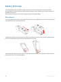
Battery Exchange . . . . . . . . . . . . . . . . . . . . . . . . . . . . . . . . . . . . . . . . . . . . . . . . . . . . . . . . . . . . . . . . . . . . . . . . . . . . . . . . . . . . . . . . . . . . 84
Microphones . . . . . . . . . . . . . . . . . . . . . . . . . . . . . . . . . . . . . . . . . . . . . . . . . . . . . . . . . . . . . . . . . . . . . . . . . . . . . . . . . . . . . . . . . . . . . . .84
Handset/Dialer . . . . . . . . . . . . . . . . . . . . . . . . . . . . . . . . . . . . . . . . . . . . . . . . . . . . . . . . . . . . . . . . . . . . . . . . . . . . . . . . . . . . . . . . . . . . .85
Speaker . . . . . . . . . . . . . . . . . . . . . . . . . . . . . . . . . . . . . . . . . . . . . . . . . . . . . . . . . . . . . . . . . . . . . . . . . . . . . . . . . . . . . . . . . . . . . . . . . . . .85
Connecting Using AUX IN/AUX OUT . . . . . . . . . . . . . . . . . . . . . . . . . . . . . . . . . . . . . . . . . . . . . . . . . . . . . . . . . . . . . . . . . . . . . . 86
BluStar for Conference Room . . . . . . . . . . . . . . . . . . . . . . . . . . . . . . . . . . . . . . . . . . . . . . . . . . . . . . . . . . . . . . . . . . . . . . . . . . . . . . .86
Third-Party Video Conferencing . . . . . . . . . . . . . . . . . . . . . . . . . . . . . . . . . . . . . . . . . . . . . . . . . . . . . . . . . . . . . . . . . . . . . . . . . . . .86
PC Applications . . . . . . . . . . . . . . . . . . . . . . . . . . . . . . . . . . . . . . . . . . . . . . . . . . . . . . . . . . . . . . . . . . . . . . . . . . . . . . . . . . . . . . . . . . . .86
Troubleshooting . . . . . . . . . . . . . . . . . . . . . . . . . . . . . . . . . . . . . . . . . . . . . . . . . . . . . . . . . . . . . . . . . . . . . . . . . . . . . . . . . . . . . . . . . . . . . 87
Warning Messages . . . . . . . . . . . . . . . . . . . . . . . . . . . . . . . . . . . . . . . . . . . . . . . . . . . . . . . . . . . . . . . . . . . . . . . . . . . . . . . . . . . . . . . . .87
Microphone, Speaker, or Handset/Dialer Not Connecting to Wireless Base Unit . . . . . . . . . . . . . . . . . . . . . . . . . . . . .88
Microphone, Speaker, or Handset/Dialer Not Paired with Wireless Base Unit. . . . . . . . . . . . . . . . . . . . . . . . . . . . . . . .88
LED Indicators. . . . . . . . . . . . . . . . . . . . . . . . . . . . . . . . . . . . . . . . . . . . . . . . . . . . . . . . . . . . . . . . . . . . . . . . . . . . . . . . . . . . . . . . . . . . . .89
Reset to Factory Defaults . . . . . . . . . . . . . . . . . . . . . . . . . . . . . . . . . . . . . . . . . . . . . . . . . . . . . . . . . . . . . . . . . . . . . . . . . . . . . . . . . . .91
Technical Specification . . . . . . . . . . . . . . . . . . . . . . . . . . . . . . . . . . . . . . . . . . . . . . . . . . . . . . . . . . . . . . . . . . . . . . . . . . . . . . . . . . . . . 92
GPL Licensed Software . . . . . . . . . . . . . . . . . . . . . . . . . . . . . . . . . . . . . . . . . . . . . . . . . . . . . . . . . . . . . . . . . . . . . . . . . . . . . . . . . . . . . . 94
GNU General Public License . . . . . . . . . . . . . . . . . . . . . . . . . . . . . . . . . . . . . . . . . . . . . . . . . . . . . . . . . . . . . . . . . . . . . . . . . . . . . . . .94
Limited Warranty . . . . . . . . . . . . . . . . . . . . . . . . . . . . . . . . . . . . . . . . . . . . . . . . . . . . . . . . . . . . . . . . . . . . . . . . . . . . . . . . . . . .Warranty-1
Exclusions . . . . . . . . . . . . . . . . . . . . . . . . . . . . . . . . . . . . . . . . . . . . . . . . . . . . . . . . . . . . . . . . . . . . . . . . . . . . . . . . . . . . . . . . . Warranty-1
Warranty Repair Services. . . . . . . . . . . . . . . . . . . . . . . . . . . . . . . . . . . . . . . . . . . . . . . . . . . . . . . . . . . . . . . . . . . . . . . . . . Warranty-1
After Warranty Service . . . . . . . . . . . . . . . . . . . . . . . . . . . . . . . . . . . . . . . . . . . . . . . . . . . . . . . . . . . . . . . . . . . . . . . . . . . . Warranty-1
Limited Warranty (Australia Only) . . . . . . . . . . . . . . . . . . . . . . . . . . . . . . . . . . . . . . . . . . . . . . . . . . . . . . . . . . . . . . . .Warranty-2
Repair Notice. . . . . . . . . . . . . . . . . . . . . . . . . . . . . . . . . . . . . . . . . . . . . . . . . . . . . . . . . . . . . . . . . . . . . . . . . . . . . . . . . . . . . . Warranty-2
Exclusions . . . . . . . . . . . . . . . . . . . . . . . . . . . . . . . . . . . . . . . . . . . . . . . . . . . . . . . . . . . . . . . . . . . . . . . . . . . . . . . . . . . . . . . . . Warranty-2
Warranty Repair Services. . . . . . . . . . . . . . . . . . . . . . . . . . . . . . . . . . . . . . . . . . . . . . . . . . . . . . . . . . . . . . . . . . . . . . . . . . Warranty-3
After Warranty Service . . . . . . . . . . . . . . . . . . . . . . . . . . . . . . . . . . . . . . . . . . . . . . . . . . . . . . . . . . . . . . . . . . . . . . . . . . . . Warranty-3
41-001516-00 REV00 – 06.2013
v
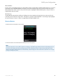
Introduction
Congratulations on your purchase of the Aastra S850i Wireless Conference Phone System. This system utilizes
state of the art technology providing high bandwidth audio and enabling clear, reliable, untethered communications with your telephone, PC, mobile device, and video conferencing system.
The S850i Wireless Conference Phone System allows enhanced freedom for VoIP calls and video conferences by
allowing independent locations of the Microphones and the Speaker used during the call.
The S850i Wireless Conference Phone System utilizes encrypted digital communication for its wireless transport,
ensuring highest security for your conversations. The S850i Wireless Conference Phone System is a flexible solution for all your communication needs, allowing it to be used in your VoIP telephone network, for your video conferences, and with your Bluetooth-enabled cell phone or computer.
Please read this documentation carefully and follow the instructions before using your S850i Wireless Conference Phone System.
6
41-001516-00 REV00 – 06.2013
Safety Warnings
Please read the following safety information before attempting to install or use the S850i Wireless Conference Phone
System.
Warning!
Do not expose any of the S850i components to water, moisture, or high humidity.
Warning!
Do not expose any of the S850i components to extreme high or low temperatures.
Warning!
Do not expose any of the S850i components to lit candles, cigarettes, cigars, or to open flames, etc.
Warning!
Do not drop, throw, or try to bend any of the components, as rough treatment could damage them.
Warning!
Do not open the casings of any of the components of the S850i Wireless Conference Phone System.
Warning!
Do not use any other accessories than Aastra’s originals intended for use with this product. Use of non-original accessories may
result in loss of performance, damage to the product, fire, electric shock or injury. The warranty does not cover product failures
which have been caused by use of non-original accessories.
Warning!
Only use the power adapter provided to connect the Charger Tray to the power outlet.
Warning!
Do not open or try to modify any of the batteries delivered with the S850i Wireless Conference Phone System components.
Replace batteries only with Aastra approved batteries.
Warning!
Extreme heat, short circuits, or any attempt to open or modify the batteries might cause them to ignite or explode.
41-001516-00 REV00 – 06.2013
7
General Information
The S850i Wireless Conference Phone System includes several components which, in the sum, make up the conferencing
phone. The components are the Charger Tray, Speaker, Microphones and Handset/Dialer.
In addition, the Wireless Base Unit receives the wireless signals from those components and connects to your VoIP network for conference calls with your video conferencing unit to provide outstanding audio for your video calls, or to your
Bluetooth-enabled device such as a cell phone or computer.
8
41-001516-00 REV00 – 06.2013
Quick Setup for VoIP Conference Calls
While all components delivered with the S850i Wireless Conference Phone System are partially charged, we recommend
charging the Speaker, the Microphones, and the Handset/Dialer for at least eight hours or overnight before starting to use
the system.
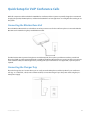
Connecting the Wireless Base Unit
Place the Wireless Base Unit close to the Ethernet outlet you want to use for the conference phone. Connect the Wireless
Base Unit to the network using the provided Ethernet cable.
The Wireless Base Unit is powered using Power over Ethernet (PoE). This requires your Ethernet outlet to provide PoE.
Please check with your IT department that PoE is available. If the Wireless Base Unit does not power up after you connect it
to the network outlet, this outlet might not be providing PoE. If your network does not support PoE, a power injector is
required.
Connecting the Charger Tray
Place the Charger Tray at a location where you can easily access the Microphones and the Speaker for your conference
calls (e.g. on a side board, a desk, or the conference table). Connect the Charger Tray to the power outlet using the provided power supply.
41-001516-00 REV00 – 06.2013
9
Quick Setup for VoIP Conference Calls
Place the Speaker, the Microphones, and the Handset/Dialer in the respective openings of the Charger Tray to charge
them. The Handset/Dialer and Speaker will automatically connect to the Wireless Base Unit after a short time if it is powered up. You will hear a confirmation chime from the Speaker once the system is ready for use. If the Speaker or the
Handset/Dialer is not powered up, take them out of the Charger Tray for a few seconds and put them back in. This will
switch on the component. To switch on the Microphones take them out of the Charger Tray. They will automatically
power up and connect to the Wireless Base Unit.
Phone Configuration
Before using the S850i for the first time, you will need to select the system language. The six options are English, Español
(Spanish), Français (French), Deutsch (German), Italiano (Italian), and Português (Portuguese).
Highlight the language of your choice, and press either “Enter” or “Select” on the Handset/Dialer to select it. Once a language is selected, the system will use that language for all screen contents. Please ensure that you select the right language. If the wrong language was selected, it can be changed in the Advanced Setup menu of th Handset/Dialer (see
"Language/Region" on page 63). If you need to change the selected language later on, this can be done in the Advanced
Setup menu of the Handset/Dialer.
VoIP Configuration
Depending on your switch, different settings will be required for your S850i to work in your environment. First of all, the
S850i will require an IP address. The IP address can either be obtained from a DHCP server in your network, or be statically set on the phone. The phone is preset to DHCP. If you want to change this, please open the menu on the Handset/Dialer by pressing the right soft key, go to the “Setup” menu, and select “Advanced Setup”. You will have to enter a
password, which is preset to 2222. Now select “Network Settings”. Under “IP Settings” you can set the required network
values like IP address, subnet mask, default gateway, and DNS servers. You will need to restart the phone for any changes
you made in this section to take effect.
If you are using DHCP, you can go to the System Info menu, and select “About System”. The assigned IP address for the
S850i will be shown here. If you configured a Virtual LAN (VLAN) for your voice traffic on your IP network, you need to
either enable VLAN on the Handset/Dialer and provide the VLAN identifier, or select “Automatic”, in which case the S850i
will try to determine the VLAN settings of your network at startup.
Independent on how the IP address of your system was assigned, the S850i has to be configured to work in your VoIP
environment and communicate with your SIP Call Server. You will have to enable the extension (user) you want to use
with the S850i on your SIP Call Server. Please review your SIP Call Server documentation on information on how to do
that. For the minimal setup, in the Handset/Dialer you will have to provide information on the IP connection to the SIP
Call Server. To do this visit Menu > Setup > Advanced Setup > Network Settings > VOIP Settings. Under Registrar, provide
the IP address or host name of your SIP Call Server. The Username should be the extension or name under which you
want to register this phone on the SIP Call Server. In Password, provide the password for this username. If no values are
provided for ID and Display Name, the Username entry will be used for them. Select “Reload Settings” after you have set
the values in the Handset/Dialer, which will restart the Wireless Base Unit.
10
41-001516-00 REV00 – 06.2013
Quick Setup for VoIP Conference Calls
If further settings are required to connect the S850i to your SIP Call Server (e.g. a proxy server) please visit the S850i Web
Interface. You get to this interface by entering the IP address of the S850i into the web browser of your choice. After you
entered the password (2222, unless you changed it in the Handset/Dialer), you can find the SIP settings under the Administrator tab on the top right. You will find the different SIP settings under SIP Registration, SIP Configuration, Transport, and
Media. You have to press Save on every page where you changed an entry to save these changes. If you do not press Save,
the changes will be lost when you leave that page. Restart the phone once you are finished with your changes.
Once the S850i is registered with the SIP Call Server, it will display the ID in the screen and is ready to make and receive
phone calls.
Making a Call
To make a conference call, take at least one of the Microphones out of the Charger Tray, and take the Handset/Dialer out of
the Charger Tray. You can remove all Microphones and the Speaker if you wish, but this is not required. Use the Handset/Dialer to enter the number you want to call, including any leading digits your VoIP telephone switch might require.
The Speaker and any Microphone that is not in the Charger Tray will be active during the call. To finish a conference call,
press the red hang-up button on the Handset/Dialer.
Note:
It is also possible to have a conference call with the Microphones in the Charger Tray. However, due to the proximity of
Microphone and Speaker at that time, audio quality might be impacted. The maximum volume of the Speaker is limited while the Microphones are in the Charger Tray. Microphones that are placed into the Charger Tray are switched off.
To use Microphones in the Charger Tray for phone calls they first have to be switched on. You do this by pressing the
button on the Microphone while it is in the Charger Tray. The Microphone will start in a muted state. Once it starts blinking red, unmute it by pressing the mute button once again. Microphones in the Charger Tray never transmit audio to
the AUX OUT connector. If any Microphone is active outside of the Charger Tray, Microphones in the Charger Tray cannot be activated (unmuted) for the call unless removed.
To make a call using the Handset/Dialer, make sure that all Microphones are in the Charger Tray before starting to dial the
number. At this point, only the Handset/Dialer will be used for the call. To end the call, press the red hang-up button on the
Handset/Dialer.
At any time during a call you can toggle between Handset and Speaker mode using the buttons on the Handset/Dialer.
To answer a call using the conference phone, simply remove one or more Microphones from the Charger Tray when the
Speaker rings. If a Microphone is already out of the Charger Tray when an incoming call comes in, pressing the button on
the Microphone will answer the call in conference phone mode. You can also use the Handset/Dialer to answer the call by
pressing the green call button on the Handset/Dialer. If all Microphones are in the Charger Tray at this time, the call will be
answered using the Speaker Mode. If at least one Microphone is switched on and not in the Charger Tray, this will answer
the call in Speaker mode.
41-001516-00 REV00 – 06.2013
11
Description
The S850i Wireless Conference Phone System is a unique marriage of innovative technology and ergonomic design,
allowing for an unparalleled experience when making telephone calls, video conference calls, or using it with your Bluetooth enabled cell phone or computer to make conference calls.
The technology used allows the Microphones, the Handset/Dialer, and the Speaker to co-exist with other wireless products such as wireless LANs (802.11b/g) without interference.
The S850i Wireless Conference Phone System includes digital encryption technology to ensure secure wireless communications between the Microphones, Speaker and the Wireless Base Unit.
Unpacking
Your S850i Wireless Conference Phone System package contains the following items:
Wireless Base Unit
2 Omnidirectional
Microphones
Charger Tray
12-15V AC Adapter
for Charger Tray
Speaker
Handset/Dialer
RJ45 Ethernet Cable
When unpacking the system be sure to take inventory of all parts to ensure that nothing is missing. If parts are missing,
please contact your retailer.
12
41-001516-00 REV00 – 06.2013
Installing S850i Components
The S850i Wireless Conference Phone System is comprised of several components that work together to provide you with
a great wireless conferencing system. These components must be setup correctly for optimal performance of the system.
S850i Wireless Base Unit
The Wireless Base Unit is the wireless receiver and transmitter of the audio stream from the Microphones to the Speaker as
well as to the Handset/Dialer. It features the ability to connect two Aastra S850i Microphones and one Speaker wirelessly.
The Wireless Base Unit is designed to optimize audio and video conferencing by providing consistent audio input from all
participants.
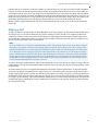
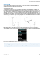
The S850i VoIP Wireless Base Unit is shown in rear panel view below. It is equipped with an Ethernet/power connection,
two mini-USB ports for firmware updates, and analog audio input/output connections for video conferencing collaboration or for recording.
Note:
The Wireless Base Unit comes equipped with the necessary cables and power supplies to perform a VoIP conference
call. Other types of conference calls performed, such as video calls and call via PC applications with the S850i may
require additional cables that are not part of the delivery.
41-001516-00 REV00 – 06.2013
13
Installing S850i Components
S850i Charger Tray
The S850i Charger Tray, shown below, provides charging capabilities for all battery operated system components, including the Handset/Dialer, the Speaker, and the Microphones, by allowing them to charge in one simple and organized location.
The S850i Charger Tray is not required while in a conference call, however it can maintain the charge of the S850i
Speaker and S850i Handset/Dialer while a call is in progress. The Charger Tray is equipped with a DC power connection
and a mini-USB connection for firmware updates to the Handset/Dialer.
14
41-001516-00 REV00 – 06.2013
Installing S850i Components
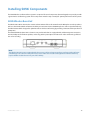
S850i Handset/Dialer
The S850i Handset/Dialer equips the user with an intuitive and interactive tool for configuring and operating the S850i
System.
The Handset/Dialer is not only used to make and answer conference calls, but it is also used for configuring the system settings, having a call using the Handset/Dialer, and monitoring the system components.
The S850i Handset/Dialer, shown below, is composed of several parts such as a color LCD screen, a compilation of buttons,
and a microphone and Handset/Dialer speaker.
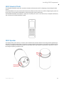
S850i Speaker
The S850i Speaker, shown below, is a wireless active omnidirectional Speaker that has been designed and optimized specifically for use with the S850i System. The Speaker is equipped with a pairing button on the bottom and 4 LED indicators
on the top to display the activity of the Speaker and the mute status of the system. The Speaker can operate in or out of
the Charger Tray during conference calls.
41-001516-00 REV00 – 06.2013
15
Installing S850i Components
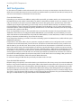
S850i Microphones
The S850i Microphones provide a sleek and unobtrusive form factor allowing for closer proximity to the participants and
creating the best audio available to the far end. They are equipped with a button for pairing and muting, an LED indicator to display mute status and battery charge level, and an internal buzzer to warn if the Microphones have lost connection to the Wireless Base Unit.
Two omnidirectional Microphones are included with the S850i. An optional lapel wearable Microphone may be purchased separately. Any combination of two S850i Microphones can be used with a S850i System as they are mix and
match.
S850i Microphones will operate in or out of the Charger Tray. It is recommended to always remove the Microphones from
the Charger Tray for conference calls as audio on the Speaker and the Microphones is limited while in the Charger Tray.
When using Microphones in the Charger Tray system behavior is automatically adjusted to the close proximity of
Speaker and Microphones. See the note in "Making a Call" on page 11 on how to activate Microphones in the Charger
Tray.
16
41-001516-00 REV00 – 06.2013
Installing S850i Components
Initial Setup
After unpacking the S850i Conferencing System, there are a few initial setup tasks that must be performed before a call
can take place or any system configuration can be changed.
Connecting System Cables
The S850i Charger Tray has a power supply that needs to be connected, as shown below. In addition, the Wireless Base
Unit needs to be connected to the network using the provided Ethernet cable before a conference call can be made. The
S850i unit expects Power over Ethernet (PoE) to be provided through the network connection. If your network does not
support PoE, a power injector is required. Please contact your reseller to purchase the additional PoE power injector. The
Wireless Base Unit offers additional optional connections that are only being used when the S850i System for example is
connected to a video conferencing unit or a recording device. The cables required for these connections are not included
with the S850i System and need to be purchased separately.
Before using the S850i to make a call, you will need to select the system language to be used for the screens. The six
options are English, Español (Spanish), Français (French), Deutsch (German), Italiano (Italian), and Português (Portuguese).
Please highlight the language of your choice, and press either “Enter” or “Select”.
Note:
If a wrong language was selected at this time, it can be changed later on the Admin area of the menu. However, you will
have to navigate through the menu to get to that option using the language you selected. Be careful that you do not
select a language you are unfamiliar with.
41-001516-00 REV00 – 06.2013
17
Installing S850i Components
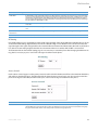
VoIP Configuration
For the S850i to work within a VoIP environment the phone has to be set up to communicate to the SIP Call Server. You
will also have to enable the extension (user) you want to use with the S850i on your SIP Call Server. Please review your SIP
Call Server documentation on information on how to do that.
From the S850i Handset
Depending on your SIP Call Server, different settings will be required for your S850i to work in your environment. First,
the S850i will require an IP address. The IP address can either be obtained from a DHCP server in your network, or be statically set on the phone. The phone is preset to DHCP. If you want to change this, please open the menu on the Handset/Dialer by pressing the right soft key, go to the “Setup” menu, and select “Advanced Setup”. You will have to enter a
password, which is preset to 2222. Now select “Network Settings”. Under IP Settings you can set the required network
values like IP address, subnet mask, default gateway, and DNS servers. You will need to restart the phone for any changes
you made in this section to take effect.
If you are using DHCP, you can go to the System Info menu, and select “About System”. The assigned IP address for the
S850i will be shown here. If you configured a Virtual LAN (VLAN) for your voice traffic on your IP network, you need to
either enable VLAN on the Handset/Dialer and provide the VLAN identifier, or select “Automatic”, in which case the S850i
will try to determine the VLAN settings of your network at startup.
If you changed any IP settings, you need to select the Load Settings option in the Network menu, which will reboot your
S850i Wireless Base Unit.
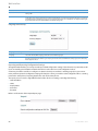
Independent on how the IP address of your system was assigned, the S850i has to be configured to work in your VoIP
environment and communicate with your SIP Call Server. You will have to enable the extension (user) you want to use
with the S850i on your SIP Call Server. Please review your SIP Call Server documentation on information on how to do
that. For the minimal setup, in the Handset/Dialer you will have to provide information on the IP connection to the SIP
Call Server. To do this visit Menu > Setup > Advanced Setup > Network Settings > VOIP Settings. Under Registrar, provide
the IP address or host name of your SIP Call Server. The Username should be the extension or name under which you
want to register this phone on the SIP Call Server. In Password, provide the password for this username. If no values are
provided for ID and Display Name, the Username entry will be used for them. Select “Load Settings” after you have set
the values in the Handset/Dialer, which will restart the Wireless Base Unit.
For enhanced settings the Web Interface provided by the S850i needs to be used.
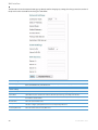
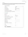
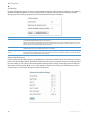
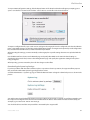
From the S850i Web Interface
If further settings are required to connect the S850i to your SIP Call Server, like a Proxy server, please visit the S850i Web
Interface. You get to this interface by entering the IP address of the S850i into the web browser of your choice. After you
enter the password (2222, unless you changed it in the Handset/Dialer), you can find the SIP configuration items under
the Administrator tab on the top right. You will find the different SIP settings under SIP Registration, SIP Configuration,
Transport, and Media. You have to press “Save” on every page where you changed an entry to save these changes. If you
do not press “Save,” the changes will be lost when you leave that page. Restart the phone once you are finished with your
changes. See "Web Interface" on page 64 for details on the S850i Web Interface.
18
41-001516-00 REV00 – 06.2013
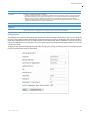
Managing A Call
The S850i Wireless Conference Phone System is equipped with a VoIP interface that allows the system to make conference
calls in a VoIP network. The following are the basic operational instructions for making and receiving telephone conference calls.
Calling Configurations
The S850i Wireless Conference Phone System has the ability to make and receive calls in many different ways. This provides the caller the ability to choose what mode or call type best suits the needs of each individual call.
Speaker Mode
Speaker Mode allows the call to take place using the Speaker and Microphones provided with the S850i System. This
allows multiple users, within the conference room, to participate in the call. It also provides the ability for the Microphones
and Speaker to be located anywhere in the conference room to meet the needs of each meeting. The call, as well as the
Speaker and Microphones, are controlled by the S850i Handset/Dialer. The user can switch between “Speaker Mode” and
“Handset Mode” while in a call.
Handset Mode
Handset Mode allows a telephone call to take place through the Handset/Dialer speaker and microphone located in the
S850i Handset/Dialer. This allows a single user to make and receive a private call. It also provides the ability for the S850i
System to act as a personal desk phone. The Microphones and Speaker are not used during a Handset/Dialer call. The user
can switch between "Speaker Mode" and "Handset Mode" while actively in a call by using the key marked “Handset” or
“Speaker”.
Note:
To switch from a Handset Call to a Speaker Call at least one Microphone should be out of the Charger Tray and switched
on, and the Speaker must be switched on. If all Microphones are in the Charger Tray at least one of the Microphones in
the Charger Tray has to be activated manually by pressing the Microphone button before switching from the Handset
Call to a Speaker Call.
VoIP Call
The S850i Wireless Conference Phone System allows making conference calls using an Ethernet VoIP connection. A telephone call can be made using either “Speaker Mode” or “Handset Mode”. A telephone call can be made at the same time
as a video call. Telephone calls are controlled via the S850i Handset/Dialer.
Bluetooth Call
The S850i System is equipped with a Bluetooth interface that supports the Hands Free Profile (HFP). This profile allows the
user to make a call through a cell phone, a computer, or other device via a Bluetooth connection. A Bluetooth call can be
made using "Speaker Mode" only. A Bluetooth call is controlled by the connected Bluetooth device. A Bluetooth call can
be made at the same time as a video call.
Note:
The S850i only supports the Hands Free Profile (HFP) for Bluetooth 2.0 or higher. Applications that try to use the Bluetooth connection not using the HFP profile, or that are using an older HFP/Bluetooth standard are not supported by
S850i.
41-001516-00 REV00 – 06.2013
19
Managing A Call
Video Conference Call
The S850i System can be connected to a video or PC conferencing system via the Analog I/O ports located on the S850i
Wireless Base Unit with additional cables. This allows the Microphones and Speaker to be used as the audio interface for
the video conference call. Video conference calls are controlled primarily by the video conference system. However,
audio properties can be controlled via the S850i Handset/Dialer. While the S850i Wireless Conference Phone System is
connected to a video conferencing device, it might still make and accept calls over the VoIP connection or via a Bluetooth device.
Notes:
• When using the S850i connected through the AUX IN and AUX OUT to another device, only the S850i Speaker can be
used. All other speakers (e.g. in a television set) must be turned off. To avoid audio problems, any Echo Cancellation
provided on the video conferencing unit should be switched off.
• For security reasons, Microphones will not send any audio signal to the AUX OUT connector when in the Charger Tray.
To receive audio signals on the AUX OUT, Microphones have to be taken out of the Charger Tray.
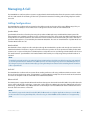
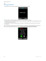
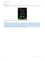
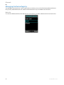
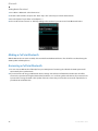
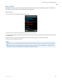
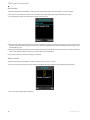
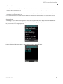
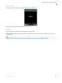
S850i Home Screen
Whenever the S850i is not in a call, the S850i Handset/Dialer will show the S850i Home Screen.
The top of the home screen shows several symbols, indicating the current status of the S850i components. From left to
right there is an indicator for the Speaker, one symbol for each of the Microphones, and a charging indicator for the
Handset/Dialer itself. The color of the Speaker and Microphone symbol indicate whether the system is available and
unmuted (green), available but muted (red), switched off (grey), or the current status is unknown, e.g. when the component was taken out of range (yellow). The Handset/Dialer charging indicator shows the current status of the battery.
Green indicates a charged battery, yellow means that the charge is getting low, and red indicates that the battery
requires re-charging. In the Charger Tray the battery indicator will show a grey symbol while charging.
20
41-001516-00 REV00 – 06.2013
Managing A Call
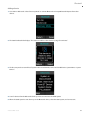
In addition, the first line will show if a Bluetooth link is currently active with a blue symbol. If the Handset/Dialer failed to
connect to the Wireless Base Unit, a red, crossed out Bluetooth symbol is shown.
In the top text line of the screen the ID or the user name with which this telephone registered to the SIP Call Server is
shown. Below that, current time and date are displayed.
From the home screen a call can be started by dialing a number, The “Do not Disturb” function of your switch can be activated for this phone, or the system menu can be entered. Whenever “Do not Disturb” is turned on, all calls to this phone
will be handled in the switch as defined in there (e.g. sent to voice mail).
The Home screen also provides information on new voice mails for the extension (if available), and on missed or rejected
calls.
41-001516-00 REV00 – 06.2013
21
Managing A Call
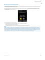
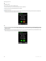
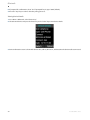
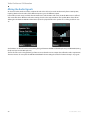
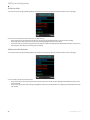
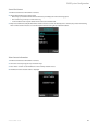
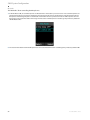
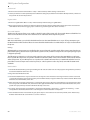
Placing a VoIP Call
1. From the home screen on the S850i Handset/Dialer enter the phone number to be called.
2. Once the number is entered completely, press the green "call" button to initiate the phone call.
3. If any Microphones are out of the Charger Tray and active, the call will default to “Speaker Mode” and will be identified by the ring
tone being played out of the Speaker.
4. If no Microphones are outside the Charger Tray the call will default to “Handset Mode” and the call will take place on the S850i
Handset/Dialer.
Once a call has been started, the home screen will show the two available phone lines and the activity on each line. In
this case, the outgoing call is being made on Line 1. The green phone symbol represents an active call.
22
41-001516-00 REV00 – 06.2013
Managing A Call
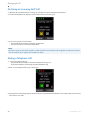
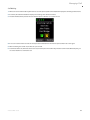
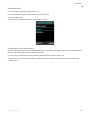
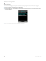
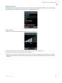
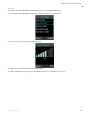
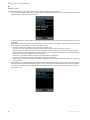
Answering an Incoming Call
1. When the S850i System identifies an incoming call, it will play the ring tone through the S850i Speaker. If the Handset/Dialer is not
in the Charger Tray it will play a ring tone, too.
2. The S850i Handset/Dialer will display the caller ID information for the incoming call. The yellow phone symbol represents an
incoming call, in this case on line one.
3. A call can be answered in one of three ways:
• Press the Green "Call" button or the "Answer" key on the S850i Handset/Dialer.
• Remove a Microphone from the Charger Tray.
• Press the mute/unmute button on a Microphone that is already out of the Charger Tray.
Note:
If there is either no Speaker active or no Microphones outside the Charger Tray when the incoming call is answered
from the S850i Handset/Dialer, the call will default to "Handset Mode" and will remain in "Handset Mode". The call can
only be switched to "Speaker Mode" if the speaker and at least one Microphone is switched on. If all Microphones are
in the Charger Tray at least one has to be switched on before by pressing the Microphone button.
41-001516-00 REV00 – 06.2013
23
Managing A Call
Declining an Incoming VoIP Call
1. When the S850i System identifies an incoming call, it will play the ring tone through the S850i Speaker.
2. The S850i Handset/Dialer will display the caller ID information for the incoming call.
3. A call can be ignored in one of two ways:
• Press the Red "End Call" button on the S850i Handset/Dialer.
• Press the "Decline" key on the S850i Handset/Dialer.
Note:
Once the user ignores the call, the telephone switch decides how to handle the call. It might for example be transferred
into voicemail, based on settings in the telephone switch.
Ending a Telephone Call
1. A call can be ended in two ways:.
• Press the Red "End Call" button on the S850i Handset/Dialer during a call.
• Place the Handset/Dialer in the Charger Tray ("Handset Mode" only).
2. When a call is ended the home screen is shown again.
3. Microphones not in the Charger Tray will maintain their mute states (muted/unmuted) when a call is ended, and will start in this state
when another call is made.
24
41-001516-00 REV00 – 06.2013
Managing A Call
Calling a Directory Contact
1. A directory contact can be called in one of two ways:
• Browse to contact menu: Menu > Contacts. Select the contact, and press the green "Call" key.
• Browse to contact menu: Menu > Contacts. Select the contact, and press the "Enter" key or the "View" key. From the contact view
screen, press the green "Call" key.
Active Call Management
The S850i System has many call features that can be used when receiving or making phone calls. These features can be
controlled via the S850i Handset/Dialer during the call.
Caller ID
1. If the incoming caller is in the Contact List, Caller ID will display both name and number of the incoming contact.
2. If the incoming caller is not in the Contact List, Caller ID will display the incoming information from the network, which might include
the telephone number and Caller ID.
Note:
An incoming Bluetooth call will display caller ID information as well if it is presented by the network.
41-001516-00 REV00 – 06.2013
25
Managing A Call
Muting a Call
1. In Handset Mode, the "Mute" and "UnMute" key will mute/unmute the S850i Handset/Dialer Microphone, not the Wireless Microphones.
2. In Speaker Mode, the "Mute" and "UnMute" key will mute/unmute all Wireless Microphones.
Note:
If the setting "All Mic Mute" is OFF, the Microphone mute buttons will be locked while the Master Mute is active. The
Master Mute can only be deactivated via the S850i Handset/Dialer. Once deactivated, the Microphones will return to
their previous mute state. If "All Mic Mute" is ON, the Mute/UnMute button on the S850i Handset/Dialer and the mute
buttons on the S850i Microphones work together. Pressing either of these buttons will mute/unmute all Microphones
out of the Charger Tray, or in the Charger Tray if no Microphone is outside.
26
41-001516-00 REV00 – 06.2013
Managing A Call
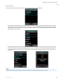
Active Call Menu
During a call, pressing the "Enter" key will open the "Active Call Menu".
This menu allows you to place a caller on hold or start a conference call based on a dialed number, a contact, or a recent
call. This menu also allows for the transferring of an active call to another number. It also provides access to the Device Status menu (see "Device Status" on page 51), Audio Controls (see "Audio Control" on page 49) and the System Info menu (see
"System Information" on page 52).
Placing a Call on Hold
1. Access the Active Call Menu by pressing the "Enter" key during a call. Select menu item "Hold". An orange phone symbol represents
a call on hold.
2. To resume the call press the "Resume" key.
41-001516-00 REV00 – 06.2013
27
Managing A Call
Conference Call
There are two ways to start a conference call:
1. Press the "Enter" key to access the Active Call Menu and select "Conference".
2. Create the second call by selecting Dialer, Contacts, or Recent.
3. Initiate the second call.
4. After the second call has been established, merge the two calls by pressing the left arrow key, which switches the Handset/Dialer
screen back to Active Call (1), and then press the "Join" key.
OR
1. While in an active call, press the right arrow key to initiate a second call via the Handset/Dialer screen. Enter the number, and press
the green "Call" button to dial the number. Please note that the caller on the active line is not put on hold until the green "Call"
button is pressed.
2. Once the second call is active, using the left and right arrow keys you can highlight the different lines on your Handset/Dialer. "Swap"
allows swapping the two calls; "Join" will join the two calls in a conference call.
28
41-001516-00 REV00 – 06.2013
Managing A Call
Call Waiting
1. While a call is active and the S850i System receives a second call, the Speaker or Handset/Dialer will play the call waiting indication tone.
2. If available, the S850i Handset/Dialer displays the incoming caller number and name.
3. The S850i Handset/Dialer presents the user with the option to "Answer" or "Decline” the call.
4. If no action is taken and the second call aborts, the S850i Handset/Dialer will show the previous Active call screen again.
5. When answering the second call, the first call is put on hold.
6. To terminate either call, make that call the active call, and then press the red "End" key. The other call will not be affected by this, you
can select "Resume" to continue that call.
41-001516-00 REV00 – 06.2013
29
Managing A Call
Component Behavior In and Out of the Charger Tray
Each system component will respond differently when placed in or out of the Charger Tray during an active telephone
call. The following is a description of what can be expected.
Handset/Dialer
When the Handset/Dialer is placed into the Charger Tray during a call in "Speaker Mode", the call will not be affected and
the Handset/Dialer will enter its charging mode.
When the Handset/Dialer is placed into the Charger Tray during a "Handset Mode" call, all calls (even calls that are currently on hold) will end and the Handset/Dialer will enter its charging mode.
When the Handset/Dialer is removed from the Charger Tray no change to call activity will take place. If there is no active
call, the Handset/Dialer will revert to the home screen.
Speaker
When the Speaker is placed into the Charger Tray during a call the Speaker will reboot and enter its charging mode. During the reboot the incoming audio from the conference call will mute until the reboot is complete (approximately 6 seconds). Once the reboot is complete the audio will resume on the Speaker.
When the Speaker is removed from the Charger Tray no change to call activity will take place.
Microphones
When a Microphone is placed into the Charger Tray during a call it will automatically reboot, switch off and enter its
charging mode. If all Microphones are placed into the Charger Tray during a Speaker Call, all Microphones will switch off
and the call will automatically switch to Handset Mode. To return to a Speaker Call a Microphone in the Charger Tray will
need to be manually switched on by pressing the mute button, and then unmuted by pressing the button again. The call
will need to be switched over to a Speaker Call using the Handset/Dialer. It is not recommended to use the Microphones
in the Charger Tray for a Speaker Call.
If at least one Microphone is outside the Charger Tray active, the Microphone in the Charger Tray cannot be unmuted
unless removed.
When a Microphone is removed from the Charger Tray, it will automatically power on and if “Start Unmute” is ON,
unmute itself. If there is an incoming call when a Microphone is removed from the Charger Tray the call will automatically
be answered.
30
41-001516-00 REV00 – 06.2013
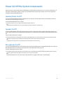
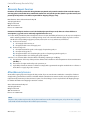
Bluetooth
The S850i System is equipped with a Bluetooth interface allowing a call to be placed through a cell phone, computer, or
third-party Bluetooth device. The S850i Microphones and Speaker then act as the Microphone and Speaker for that call.
The S850i System only supports the Hands Free Profile for Bluetooth 2.0 or newer. Should the application on the computer, cell phone, or other 3rd party device require other profiles to be supported, S850i cannot act as the Speaker and
Microphone for that application. Please contact the provider of the application to find out which Bluetooth profile can be
supported.
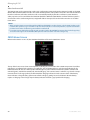
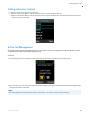
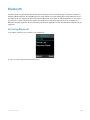
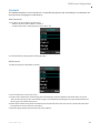
Activating Bluetooth
1. Go to Menu > Bluetooth. Select "Turn On" to activate Bluetooth.
2. Select "Yes" when prompted 'Enable Bluetooth Radio?'.
41-001516-00 REV00 – 06.2013
31
Bluetooth
Managing the Device Registry
The S850i Bluetooth interface has a device registry where it activates, stores and recalls third-party Bluetooth devices
being used by S850i for Bluetooth calls. S850i can hold information for up to four Bluetooth connections.
Device List
To see the list of Bluetooth devices the S850i has been connected to, go to Menu > Bluetooth and select "Device List".
32
41-001516-00 REV00 – 06.2013
Bluetooth
Adding a Device
1. Go to Menu > Bluetooth. Select "Discovery Mode" to activate Bluetooth and accept Bluetooth Request from other
devices.
2. The S850i Handset/Dialer displays “This device is visible to other devices in range for 3 minutes”
3. The discovery mode screen will read “System in Discoverable Mode, Start Scan From BT Device. System Name: <System
Name>”.
4. Scan for devices from the Bluetooth device you want to connect to the S850i System.
5. When the S850i System’s name shows up on the Bluetooth device, select the S850i System, and connect to it.
41-001516-00 REV00 – 06.2013
33
Bluetooth
6. If prompted for confirmation, select "Yes". If prompted for pin, type "0000" (default).
7. Press the "Stop" key in order to abort the pairing processes.
Viewing Device Details
1. Go to Menu > Bluetooth. Select "Device List".
2. Select desired device and press the "Enter" key or the "Select" key to view device details.
3. Device Information screen is shown with device name, address, BT version, and date/time the device was first connected.
34
41-001516-00 REV00 – 06.2013
Bluetooth
Removing a Device
1. Go to the Menu > Bluetooth. Select "Device List".
2. Select desired device and press the "Enter" key or the "Select" key.
3. Press the "Option" key
4. Select "Unpair" in the Device Options menu, and press "Select".
Accepting Device Connection Request
If the trust setting for a previously paired Bluetooth device is set to "Ask" and that device comes into range with the S850i
System, a message will appear on the S850i Handset/Dialer.
1. Select "Yes" to have the S850i System pair with the Bluetooth device and be ready for use.
2. Select "No" to have the S850i System ignore the Bluetooth device until the next time it comes into proximity of the
S850i System.
41-001516-00 REV00 – 06.2013
35
Bluetooth
Setting Device Trust Level
1. Go to Menu > Bluetooth. Select "Device List".
2. Select the desired device and press the "Enter" key or the "Select" key to view the device details.
3. Press the "Option" key and then select "Options…".
4. Choose either "Auto-Connect" or "ASK" depending on the trust level you want to set for the Bluetooth Device.
Making a Call via Bluetooth
With the Bluetooth connection enabled, dial a number from the Bluetooth device. The call will be conducted using the
S850i Speaker and Microphones.
Answering a Call via Bluetooth
1. You can answer a Bluetooth call directly from your S850i System. If answering the call with the S850i System it will
automatically be in Speaker Mode.
2. If you answer the call using your Bluetooth device, settings on that device will determine whether the call will be
answered as a Speaker Call using the S850i Conference Phone, or as a call using other audio devices. If you want to have
a private call not using the S850i as the Speaker of the call, ensure that you select the correct audio output device in
your Bluetooth-enabled device.
36
41-001516-00 REV00 – 06.2013
Video Conference Collaboration
The S850i System is equipped with balanced analog audio input and output to be connected to Aastra’s BluStar for Conference Room solution or PC conferencing system. This allows the S850i Microphones and Speaker to be used as Microphones and Speaker for video calls. It also provides Acoustic Echo Cancelation and Noise Control to the video call.
Connecting a Video Conference System
In the Advanced Audio setting (see "Advanced Audio" on page 55), change the Aux Audio setting for Aux Out to MIC. Then
connect one of the AUX OUT on the S850i Wireless Base Unit via an appropriate mono balanced or unbalanced cable with
3.5mm plugs to the "Mic Input" on the video conference system.
The line level audio AUX IN on the S850i Wireless Base Unit should be connected, via the appropriate mono balanced or
unbalanced 3.5mm cable, to the "line output" of the video conference system.
As the S850i System provides the Echo Cancellation for the call, any Echo Canceller in the video conferencing unit should
be switched off. Not switching off the Echo Canceler in the Video Conferencing unit might negatively affect the audio on
the S850i Speaker and Microphones. Please visit the documentation of your video conferencing unit on how to disable the
Echo Canceller.
Any audio device like external speaker or TV speaker attached to the video conferencing unit needs to be disabled. The
S850i Speaker and Microphones become your only audio devices for the video conferencing call. Any other devices will
affect the Echo Canceller and will cause negative impact on the audio of the call.
Note:
For security reasons the S850i Microphones will not send any audio to the AUX OUT while in the Charger Tray. The
Microphones have to be removed from the Charger Tray to send audio data to the AUX OUT connector.
Configuring the Analog Audio
The AUX IN and AUX OUT connectors have to be configured in the right way to receive best results with your video conferencing unit. This requires testing and setting of the values in your environment. See "Advanced Setup" on page 55 on setting the volume for the AUX IN and AUX OUT connectors and how to set the level (Microphone level or Line level) for the
AUX IN connector.
Making a Video Call
The S850i System acts as a wireless Microphone, Speaker and mixer for the video conference call. Simply remove the
Microphones from the Charger Tray to activate the analog audio input.
41-001516-00 REV00 – 06.2013
37
Video Conference Collaboration
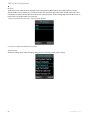
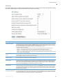
Mixing the Audio Signals
As discussed earlier, Audio and Video, or Bluetooth and video calls can be made simultaneously from a S850i System,
requiring S850i to mix the audio of the different inputs to go to the different outputs.
In the Audio Controls menu, available from the Main menu and the Active Call menu, the Audio Mixer menu is offered.
This menu offers three different audio mixer settings, based on the output medium. The Speaker Mixer shown allows
defining the mix between AUX IN and the Phone input to be played back on the Speaker. It is a sliding scale from -8 to
+8.
Similar Mixers are offered for Phone Out (mixing the signal between AUX IN and the Microphones), and AUX OUT (mixing
the phone input and the Microphones).
The mix of audio can be changed during call time to ensure that the various outputs best reflect the audio requirements.
The mixer menus do not replace the AUX IN and AUX OUT volume settings described in "Advanced Setup" on page 55.
38
41-001516-00 REV00 – 06.2013
S850i System Configuration
There are many features to the S850i System that can be modified and configured using the S850i Handset/Dialer. The following is a list of those features and their options.
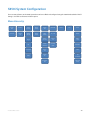
Menu Hierarchy
Recent
Calls
Contacts
Audio
Controls
Device
Status
System
Info
Bluetooth
Call List
Contact
List
Speaker
Volume
Device
Status
About
System
On / Off
Display
Ringer
Device
Versions
Device
List
Date /
Time
EQ
System
Versions
Discovery
Mode
Bluetooth
Audio Mixer
Device
IDs
Audio
Mute
System
ID
Call
Forwarding
Bluetooth
Info
Advanced
Setup
41-001516-00 REV00 – 06.2013
Home
Call
Setup
39
S850i System Configuration
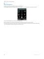
Menu Navigation
1. Enter the menu by pressing the "Menu" softkey in the home screen.
2. The Left, Right, Up and Down navigation keys are used to highlight an icon and the Enter key is used to make a selection.
3. Up and Down navigation keys are used to scroll through the menu.
4. When setting levels, such as Volume, in the menus, the Up and Down keys are used to change these values.
5. You leave the menu either by pressing the "Return" softkey, which will bring you back one level in the menu hierarchy, or by pressing
the red hang-up button, which will bring you back to the home screen.
40
41-001516-00 REV00 – 06.2013
S850i System Configuration
Recent Calls
The Recent Calls call log stores the contact information from calls placed or received, allowing the user to review recent
calls, redial a recent call, or store a recent call in the system directory.
Recent Call Log
1. Access the recent call log by browsing: Menu > Recent Calls
2. The recent call list is sorted chronologically with the most recent call at the top.
3. If a recent call was made by a number stored in the Contact list, the contact name is shown in this list, otherwise the caller ID or dialed
number is shown.
4. The recent call log can be accessed directly from the home screen by pressing green "Call" button in idle state.
5. The recent call log is limited to 20 entries.
Notes:
• Recent calls are color coded by type. Dialed calls appear blue, received calls appear green, and missed calls appear
red.
• The recent call log can be deactivated in the Advanced Setup menu (see "Recent Calls ON/OFF" on page 60). If it is
deactivated, no logs will be kept, the recent call log will always be empty.
41-001516-00 REV00 – 06.2013
41
S850i System Configuration
Call Recent Caller
1. Access the recent call log by browsing: Menu > Recent Calls or pressing the green "Call" button while no call is in progress.
2. You can call an entry in the recent caller list in one of three ways:
• In the recent call list, select the entry you want to call using the up and down buttons, and press the "Call" softkey.
• Pressing the green "Call" key will also call the entry currently highlighted in the recent call list.
• In the recent call list, select the entry you want to call, and press "View". This displays more information. From that screen, you can
press the green "Call" key to call the entry you are viewing.
View Recent Call Information
1. Access the recent call log by browsing: Menu > Recent Calls or pressing the green "Call" button while no call is in progress.
2. You can view a recent call one of two ways:
• In the recent call list, select the entry you want to view, and press the "View" key. This displays more information for the recent
call you selected.
• In the recent call list, press enter to bring up the Options menu. Select "View Recent Call" to display more information for the call
you selected.
42
41-001516-00 REV00 – 06.2013
S850i System Configuration
Save Recent Caller as Contact
1. Access the recent call log by browsing: Menu > Recent Calls or pressing the green "Call" button while no call is in progress.
2. In the recent call list, select the entry you want to add to the contacts, and press "View". This displays more information for the recent
call you selected.
3. Press the "Save" key to save the recent call as a Contact. If a caller name was provided as part of the Caller ID it will be provided as
the contact name. Enter or edit the contact name when prompted and press "Done". Verify and edit if necessary the recent contact
number and press "Done" again.
Delete Recent Call Entry
1. Access the recent call log by browsing: Menu > Recent Calls or pressing the green "Call" button while no call is in progress.
2. In the recent call list, select the contact you want to delete, and press the "View" key. This displays more information for the call you
selected.
3. Press the "Delete" key to delete the recent call. Press "Yes" when prompted for confirmation.
41-001516-00 REV00 – 06.2013
43
S850i System Configuration
Delete Call History
1. Access the recent call log by browsing: Menu > Recent Calls or pressing the green "Call" button while no call is in progress.
2. In the Recent Call menu, press "Enter" to open the Options Menu.
3. In the Options Menu select "Delete Redundant" to delete redundant call history information, or select "Delete All Calls" to delete
all call history information.
4. Press "Yes" to delete the information when prompted for confirmation.
44
41-001516-00 REV00 – 06.2013
S850i System Configuration
Contacts
The S850i Handset/Dialer can store 100 entries in a contact directory (phone book). The following is a list of features and
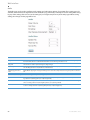
menus that allow managing the contact directory.
View Contact List
1. The contact list can be viewed in one of two ways:
• Browse to the Contacts menu: Menu > Contacts, or
• From the home screen, in idle/ready state, press the “Enter” key.
2. To leave the Contacts menu, press the red hang-up button.
Add a Contact
1. Browse to the Contacts menu: Menu > Contacts.
2. Press the "New" key to create a new contact.
3. Edit the name in alphanumeric mode. Pressing "Clear" while editing the name will delete the character left of the cursor. Press
"Cancel" to return to the previous screen without saving the contact. When finished editing the name, press the Enter button. This
will bring you to the number editing screen.
4. Edit the phone number. The key "Clear" will delete the character to the left of the cursor. Press "Cancel" to return to the name editor.
Pressing Enter will store the new contact in memory.
5. Once the editing is finished, the menu will return to the contact list.
41-001516-00 REV00 – 06.2013
45
S850i System Configuration
Edit a Contact
1. Browse to the Contacts menu: Menu > Contacts, scroll to the desired contact, and select "View" to access the contact.
2. The contact screen shows the current name and number. Pressing the "Edit" key will open the Edit Contact menu.
3. In the Edit Contact menu, select "Edit Info" to edit the selected contact.
4. Edit the name in alphanumeric mode. Pressing "Clear" will delete a character to the left of the cursor. Press "Cancel" to return to the
previous screen without saving changes to the contact name. Pressing the Enter key will finish editing the name and go on to the
number editing screen.
5. Edit the phone number. The key "Clear" will clear/delete the number to the left of the cursor. Press "Cancel" to return to the Name
editor screen. When finished, press "Enter" to store the edited contact in memory.
6. The contact list menu is shown once editing is completed.
Delete a Contact
1. Browse to the Contacts menu: Menu > Contacts and press "View" to access a contact.
2. The contact view screen shows the contact name and number. Pressing the "Delete" key will delete the selected contact.
3. Press "Yes" when prompted for confirmation.
46
41-001516-00 REV00 – 06.2013
S850i System Configuration
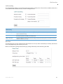
Search for Contact
1. Browse to the Contacts menu: Menu > Contacts.
2. Use the alphanumeric keys to apply a filter:
• Once a key is pressed the title line will read "Contact()" and display the characters being typed.
• The search string can be up to 5 characters long.
• In this mode the "Clear" key will delete the last character in the filter field.
3. Only contact items that satisfy the filter will be shown in the contact screen. For example, if "C" is entered, any contact name starting
with "C" will be shown. The user can scroll through the filtered list using the up and down buttons.
View Contact Information
1. Browse to the Contacts menu: Menu > Contacts.
2. Select the contact by using the "up" and "down" keys.
3. Press "Enter" or "View" to see information on the currently selected contact.
4. Information for the selected contact is displayed.
41-001516-00 REV00 – 06.2013
47
S850i System Configuration
Call Contact
1. Browse to the Contacts menu: Menu > Contacts.
2. Select the contact by using the "up" and "down" keys.
3. Press the green "Call" key to call the contact currently highlighted.
4. Pressing the green "Call" key from the contact view screen will also initiate a call.
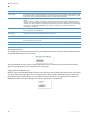
Set Speed Dial
1. Browse to the Contacts menu: Menu > Contacts, scroll to the desired contact, and press the "View" key to access the contact.
2. The contact view screen shows the current name and number. Pressing the "Edit" key will open the Edit Contact menu.
3. In the Edit Contact menu select "Edit Speed Dial".
4. Scroll to the desired speed dial number and press the "Set" key.
5. If this speed dial number is already set, an overlay will appear asking "Overwrite Speed Dial X?"
Calling a Speed Dial Number
To call a speed dial number, from the dial menu or from the home screen, press and hold the number key of the speed
dial contact you want to call until the screen changes, showing that S850i is dialing the number.
Pressing and holding a number key that has not yet been assigned to a contact has no effect.
48
41-001516-00 REV00 – 06.2013
S850i System Configuration
Audio Control
The following is a list of S850i Handset/Dialer menus that adjust the system attributes related to Speaker audio, Analog
audio inputs/outputs, telephony audio configurations, and muting Microphones.
Speaker Volume
1. Browse to the Speaker Volume menu: Menu > Audio Controls > Speaker Volume.
2. The Speaker Volume screen is shown with graph and numerical value of the current volume level.
3. Press the up and down buttons to increase or decrease the volume.
4. During an active call or while in the home screen you can also set the volume by pressing the up and down buttons. In Speaker
Mode or while in the home screen the Speaker volume is set from this command. In Handset Mode the volume on the Handset/Dialer
is adjusted.
41-001516-00 REV00 – 06.2013
49
S850i System Configuration
Ringer
1. Browse to the Ringer menu: Menu > Audio Controls > Ringer.
2. Choose "Ringer Volume" in the Ringer Settings menu to adjust the Ringer Volume.
3. Press the up and down buttons to increase and decrease the volume.
4. Choose "Ring Tone" in the Ringer Settings menu to select a ring tone.
5. Use the up and down buttons to select a ring tone, and press enter to set the selected ring tone.
6. The selected ring tone is shown in yellow upper case letters.
Equalizer (EQ)
1. Browse to the Equalizer Settings menu: Menu > Audio Controls > EQ.
2. Use the up and down buttons to select a preset EQ, and press enter to set the selected EQ.
3. The selected equalizer will be listed in yellow upper case letters, while the others are listed in lower case letters. In the example to
the right, VOICE is the selected EQ Setting.
Audio Mixer
The Audio Mixer menu is described in "Mixing the Audio Signals" on page 38.
50
41-001516-00 REV00 – 06.2013
S850i System Configuration
Mute/UnMute
During a phone call or Bluetooth call one of the softkeys allows to master-Mute or UnMute all Microphones. In an environment where only the AUX OUT/AUX IN connections are used for audio this option does not exist on the home screen.
Mute/UnMute in the Audio Control menu provides this option. Highlight the Mute/UnMute option, and press "Enter" to
toggle between the two modes.
Mic Warning
The Mic Warning setting allows enabling or disabling the voice prompt that is being played once a phone calls ends,
reminding users to return the components – Microphones, Speaker, and Handset/Dialer – to the Charger Tray. Highlight
the option and press “Select” or “Enter” to toggle between the ON and OFF mode.
Device Status
1. Browse to Device Status: Menu > Device Status.
2. The Device Status screen shows status for the Microphones and the Speaker.
Note:
The device status list is color coded. If a device is charging or off, it will appear white. If a device is fully charged or has
more than 50% battery remaining, it will appear green. Once the battery level of a device drops below 50% it will
appear orange in the device status list. A critical battery status will appear red. If a device has lost its link or is no longer
in range, it will appear yellow.
41-001516-00 REV00 – 06.2013
51
S850i System Configuration
System Information
The following is a list of S850i Handset/Dialer menus that allow the user to retrieve system information.
System Info
1. Browse to System Info: Menu > System Info.
2. About System shows the IP Address, firmware (FW) bundle version, the System Name, phone type information, and the extension
number (logon) to the telephone switch.
3. Device Versions shows firmware version for the Speaker (SPK) and Microphones (MICx).
4. System Versions shows the firmware versions for the Application (APP), Baseband (BB), Bluetooth Base (BTB), and Bluetooth Dialer
(BTH) software.
5. Device IDs shows the ID of the Speaker (S1) and the Microphones (Mx).
6. System ID shows the ID of the Wireless Base Unit.
7. Bluetooth Info shows information on the Bluetooth link between the Handset/Dialer and the Wireless Base Unit, including signal
strength ("Link Info"). Under "Bluetooth Status" it provides information about the Bluetooth identifiers, and which Bluetooth profiles
are currently in use.
Bluetooth
The "Bluetooth" menu has been explained earlier in "Bluetooth" on page 31.
Home
When selecting the "Home" menu item, the Handset/Dialer will go back to displaying the home screen. The same effect
can be achieved by pressing the "Return" key, or the red "End Call" button.
Call
When selecting "Call" in the menu, the Handset/Dialer will open the Handset/Dialer menu, allowing entering and dialing
a number.
Setup
Setup is divided into a generic area of features that are not password protected and Advanced Setup, which requires a
password.
52
41-001516-00 REV00 – 06.2013
S850i System Configuration
Display
1. Browse to the Display menu: Menu > Setup > Display.
2. The Display menu offers five options: Contrast, Brightness, Backlight time, whether the backlight is on or off while the Handset/Dialer
is in the Charger Tray, and to switch Network Alerts “Registration Failed” on or off.
3. Use the up and down buttons to highlight the setting you want to change, and press either "Enter" or "Select" to open that setting
or change the setting.
4. Use the up and down buttons to increase or decrease the respective values.
41-001516-00 REV00 – 06.2013
53
S850i System Configuration
Date/Time
1. Browse to the Date/Time menu: Menu > Setup > Set Date/Time.
2. To set the date or time, select either the "Set Date", or "Set Time" option, and press either "Enter" or "Select".
3. Edit time and date (month/day/year) using the numeric keys and the left and right buttons. The "Done" key will store the value;
"Cancel" will discard any changes you entered. To change the use of the network time, select the “Netwrk Time ON/OFF” option. You
change the setting by pressing the “Select” key. If you select “Netwrk Time ON” the S850i will attempt to derive the date and time
from the IP network.
4. Date Time Format leads to a sub menu where the format in which date and time are displayed can be selected. The time format can
be set to 12 Hr or 24 Hr format depending on user preference. The offered date formats are MM/DDYY, DD/MM/YY, or YYMMDD. While
highlighting either setting, the “Enter” or “Select” key will change the different settings.
5. Time Zone allows the user to choose what the GMT offset at their location is.
6. Daylight Savings Time can be set ON or OFF. The rules when daylight savings time starts and ends have to be specified in the Web
Interface.
Bluetooth and Audio
The menu entries for Bluetooth and Audio in the setup menu will open the top level menus of the same name described
earlier in this documentation.
54
41-001516-00 REV00 – 06.2013
S850i System Configuration
Call Forwarding
1. To always forward incoming calls, switch "Always" to "ON" and enter the number to which to forward the calls.
2. To forward calls to another number when “Do not Disturb” is selected or both lines are busy, switch "Busy" to "ON", and enter the
number to which to forward the calls.
3. To forward incoming calls when the call is not answered on the S850i System in a specific time, switch "No Answer" to "ON", and enter
the number to which to forward the calls.
4. To set the time before the call is forwarded to the "No Answer" number, select "No Answer Delay" and set the time in seconds.
Advanced Setup
The following is a list of advanced configuration settings that are protected by a four-digit password for administrator
access only. The default password is 2222. This password should be changed by the system administrator. Please ensure
that you take note of the changed password.
Advanced Audio
Browse to Advanced Audio menu: Menu > Setup> Advanced Setup> Advanced Audio.
41-001516-00 REV00 – 06.2013
55
S850i System Configuration
Mic Audio
The "Mic Audio" allows controlling the Microphones.
1. If "All Mic Mute" is ON, all active Microphones are affected when a mute button is pressed. If one or more active Microphones are
outside the Charger Tray, pressing the mute button will change the mute status on all Microphones outside of the Charger Tray.
Microphones in the Charger Tray will not be affected and will remain off or stay muted at all times. If all Microphones are in the
Charger Tray, pressing the mute button will change the mute status of all Microphones in the Charger Tray. The factory default for
"All Mic Mute" is OFF.
2. The "Start Unmute" feature allows the Microphones to come out unmuted when taken out of Charger Tray. The factory default is ON.
56
41-001516-00 REV00 – 06.2013
S850i System Configuration
Aux Audio
"Aux Audio" is to control the AUX In and AUX Out connectors on the Wireless Base Unit.
1. Aux In ON/OFF and Aux Out ON/OFF allow enabling/disabling the Aux connectors of the S850i.
2. Aux In Level allows changing the level of the Aux In signal.
3. Aux Out Level allows changing the level of the Aux Out signal.
4. Aux Out – MIC/LINE allows setting the level of the Aux Out connectors to either Mic level or Line level.
41-001516-00 REV00 – 06.2013
57
S850i System Configuration
RF Power
The RF Power level setting allows changing the signal strength of the Wireless Base unit and Microphones. Factory
default is HIGH. Low or medium can be selected to reduce the signal strength. Lower signal strength reduces the maximum distance between Wireless Base Unit and any of the wireless devices. A lower setting might be desirable in environments where a lot of DECT traffic is encountered.
1. Browse to the RF Power menu: Setup > Advanced Setup> RF Power.
2. The user can adjust the RF Power from low to high.
Admin Settings
The Admin Settings menu allows changing settings that are related to general system settings.
58
41-001516-00 REV00 – 06.2013
S850i System Configuration
Setting System Name
1. Go to Menu > Setup > Advanced Setup > Admin Settings > Set System Name.
2. Change the current System Name to the new name, and press Enter.
Reset Defaults
1. Go to Menu > Setup > Advanced Setup > Admin Settings > Reset Defaults.
2. Resetting defaults will revert back to factory defaults. Pairing of devices, recent calls, stored contacts, and the system name are not
affected by this.
Note:
Besides other values, “Reset Defaults” will reset the admin password to the factory default (i.e. 2222).
41-001516-00 REV00 – 06.2013
59
S850i System Configuration
Set Password
1. Browse to the Set Password menu: Menu > Setup > Advanced Setup> Admin Settings >Set Password.
2. Set the password to an admin specified password. Note that setting this password will override the default password, so make sure
that you will not lose the new password.
Log Out Admin
1. Browse to Log Out Admin: Menu > Setup > Advanced Setup> Admin Settings >Log Out Admin.
2. Once logged out, the user will have to retype the admin password to enter the administrative menus again. If the user leaves the
administrative menus without logging out, an automatic log-out will happen after about 15 minutes.
Recent Calls ON/OFF
The Recent Calls option allows you to enable or disable logging of the recent calls. If you switch Recent Calls OFF the list
of the recent calls will be erased and no information on recent calls will be kept in the system.
Web Access ON/OFF
Web Access OFF allows you to disable the Web Interface into the S850i. If Web Access is set to off, any attempt to open
the Web Interface will be declined. Please be aware that if the Web Interface is switched off, it can only be restarted from
the phone.
Pairing
All S850i wireless components are paired before the system is shipped, providing much of the system setup already completed. While pairing should not be required for the system to work, sometimes components can require pairing if a part
is shipped separately.
The following are instructions on how to pair the wireless components of the system to the S850i Wireless Conference
Phone System. All components are paired to the Wireless Base Unit, which is the central unit that communicates with all
other components. To pair a Microphone or a Speaker to the S850i Conference Phone, a S850i Handset/Dialer has to be
paired first. If several components need to be paired, or a whole system needs to be paired, start with the S850i Handset/Dialer.
Handset/Dialer
1. Turn off the Handset/Dialer by pressing and holding the red "end call" button until an overlay appears asking whether you want to
shut the Handset/Dialer down. Press "Yes".
2. Plug in the S850i Wireless Base Unit.
3. Turn the Handset/Dialer back on (press the red "end call" key). The screen should read “Scanning for new base”. If the screen reads
“scanning for paired base”, press the "Stop" button, press the "Menu" button, navigate to “Advanced", and select "Re-Pair". When asked
whether to "Scan for New Base", select "Yes".
4. After some time scanning for available bases, an overlay will appear asking "Pair with <System Name>?" The system name is either
the Factory preset name of AAST..xxxx, with xxxx the last 4 digits of the BT number on the bottom of the Wireless Base Unit, or the
system name you previously selected in the Advanced Setup. Select "Yes".
5. An overlay, "Pairing with base <System Name>", should appear followed by a "Connecting…" and then an "Initializing…" screen.
Shortly after that the Handset/Dialer home screen will appear. Your Handset/Dialer is now paired.
6. If the Handset/Dialer does not automatically pair, repeat steps 1-5. If this still does not resolve the problem, select “Reset Factory
Defaults” under "Advanced" as this will force a scan for a new base.
60
41-001516-00 REV00 – 06.2013
S850i System Configuration
Speaker
1. To pair a Speaker first turn it off by pressing and holding the button on the bottom of the Speaker until you hear the Speaker shutoff or the LEDs turn off.
2. Ensure that the Wireless Base Unit is plugged in and powered up.
3. On the Handset/Dialer, browse to the Pairing menu: Menu > Setup > Advanced Setup > Pairing.
4. Select SPK 1 (Speaker 1) and press the "Enter" or "Pair" key to enter pairing state.
5. The screen will display "Pairing Speaker 1".
6. Press and hold the button on the bottom of the Speaker until the LED turns solid red. The Speaker is now in pairing mode.
7. After a short time an overlay will appear on the S850i Handset/Dialer saying "Pairing Successful", after which the screen should read
"SPK 1 Linked".
8. If pairing was unsuccessful, the Speaker will show an alternating red -green slow blinking sequence indicating that the pairing
failed. The Handset/Dialer will display a "Pairing Timeout" message. In that case the pairing procedure should be repeated.
Microphone
1. To pair a Microphone, turn off the Microphone by holding the mute button until the LED turns red if it is not already turned off.
2. Ensure that the Wireless Base Unit is plugged in and powered up.
3. On the Handset/Dialer, browse to the Pairing menu: Menu > Setup > Advanced Setup > Pairing.
4. Select MIC 1 (Microphone 1) or MIC 2 (Microphone 2) and press the "Enter" key to enter pairing state.
5. The screen will display "Pairing Mic 1" or "Pairing Mic 2" depending on which Microphone you are pairing.
6. Press the mute button on the Microphone and hold it until the LED turns solid red. The Microphone is now in pairing mode.
7. After a short time an overlay will appear on the Handset/Dialer "Pairing Successful", after that the screen should read "MIC 1 Linked"
or "MIC 2 Linked", based on which one you were pairing.
8. If pairing was unsuccessful, the Microphone will show an alternating red - green slow blink sequence, indicating that the pairing
failed. The Handset/Dialer will display a "Pairing Timeout" message. In that case the pairing procedure should be repeated.
LED Pairing Indicators
Speaker Indicator
Status
Steady Red
Speaker is in Pairing Mode, either waiting or pairing in progress
Slow red- green flash
Pairing failed or timed out
Green flash
Pairing successful
Microphone Indicator
Status
Steady Red
Pairing Mode, either waiting or pairing in progress
Slow red- green flash
Pairing failed or timed out
Green flash
Pairing successful
41-001516-00 REV00 – 06.2013
61
S850i System Configuration
Network Settings
1. Browse to the Network Settings menu: Menu > Setup > Advanced Setup > Network Settings.
• You can change the DHCP configuration by turning it off and manually setting your IP address in the IP Settings. If DHCP is set
to ON this takes precedent over static IP settings.
• IP Settings allows you to set the IP Address, Subnet Mask, Default Gateway, Primary DNS and Secondary DNS when you are not
using DHCP.
• VoIP Settings allow you to set minimal required settings to connect to a VoIP switch. Registrar, Username, and Password (which
can be empty) are required fields to connect to your SIP Call Server.
– "Registrar" is either the IP address or server name of your SIP Call Server.
– "ID" is the name used in messages to identify this phone. If ID is left open, the Username will be used as ID.
– "Display Name" is the string that is shown at the far side when you make outbound calls. If you do not provide a Display
Name, the Username will be used. Please note that your SIP Call Server might override the Display name sent by the S850i
and replace it with names configured in the SIP Call Server.
– "Username" is the extension off the SIP Call Server this phone will be reached under
– "Password" is the password used by the Username to logon to the SIP Call Server.
– If any value was changed, a sixth option "Load Settings" is offered. This will reboot the S850i Wireless Base Unit, applying the
changed settings.
• Voice VLAN allows changing VLAN settings. Highlight the “Mode” field and press “Enter” to switch between the three options.
“Auto” will automatically determine whether a VLAN is in place, and request the VLAN identifier from the network. “Enabled”
will enable the VLAN, but requires a VLAN identifier to be manually set in the Voice VLAN ID menu. “Disabled” means that no
Voice VLAN is in use.
62
41-001516-00 REV00 – 06.2013
S850i System Configuration
Language/Region
1. Browse to the Network Settings menu: Menu > Setup > Advanced Setup > Language/Region.
• The Language submenu allows selecting the dialer language from one of the six supported languages: The options are English,
Español (Spanish), Français (French), Deutsch (German), Italiano (Italian), and Português (Portuguese). Highlight the language
of your choice, and press either “Enter” or “Select” on the Dialer to select it. Once a language is selected, the system will use that
language for all screen contents.
• The Country/Region submenu allows selecting the local Country or region. Please ensure that this selection is always set to your
local country or region. Changing this setting might lead to loss of connectivity to the Microphones and speakers. If your Microphones and speakers do not automatically reconnect after changing the Region setting, you need to pair all of them again to
your system.
Note:
We recommend changing the Region setting only after previous consultation with Aastra support.
41-001516-00 REV00 – 06.2013
63
Web Interface
The S850i Web Interface provides access to advanced configuration settings, call statistics and system logs. Web access
can be enabled or disabled from the S850i Handset/Dialer, and the Web Interface is password protected using the same
password that is required to access Administrator settings on the S850i Handset/Dialer.
This section describes the Web Interface and is organized as follows:
• Enabling Web Access
• Connecting to the S850i Web Interface
• Home Page
• User Settings
• Administrator Settings
The Administrator Settings section also describes how S850i configuration settings can be imported and exported to aid
in configuring multiple S850i Systems in an enterprise.
Enabling Web Access
To enable the Web Interface, from the S850i Handset/Dialer select Menu > Setup > Advanced Setup, enter the administrator password, then select Admin Settings > Web Access ON/OFF. Press the Enter button to toggle between ON and
OFF to control access. Factory default is web access enabled. To change the password needed to access both the Web
Interface and advanced settings on the Handset, see "Set Password" on page 60. The Web Interface also includes a web
session timeout to protect against unwanted access if the session is left open for more than fifteen minutes.
Connecting to the S850i Web Interface
To use the Web Interface, open a web browser and navigate to the IP address of the S850i. If you do not know the IP
address of your S850i System, on the Handset/Dialer open the menu, System Info, About System. The IP address is listed
here. The Login page will appear as shown below.
Enter the administrator password and click Login.
After logging in, the S850i Home page will appear. The S850i Web Interface is organized into three categories: Home,
User and Administrator. Choose any one of these categories by clicking on the corresponding link in the upper right corner.
64
41-001516-00 REV00 – 06.2013
Web Interface
Home Page
The Home page shows general information about the system as shown below.
The Product field is a brief description of the S850i to which you are connected. The System IP Address shows the IP
address of the device, whether it was configured by DHCP or with a static IP address. The Physical Address is the MAC
address of the phone. The remaining fields show the software versions of the S850i Wireless Base Unit, Speaker and Microphones, respectively. If the Microphones have not been removed from the Charger Tray, the Microphone versions may be
shown as “unknown.” To update these fields, remove the Microphones from the Charger Tray, wait a few seconds for the
phone to detect the Microphone state, and then refresh the web page by selecting your browser’s refresh option. If the
Microphones or the Speaker still do not show a version number, verify that these components are paired properly. See the
pairing instructions in this document. If no second speaker is used with the system, that entry will always show “unknown”.
User Settings
In the upper right corner click the User link to access the User settings. The User Menu will appear on the left side of the
page showing these options:
• Audio
• Call Forwarding
• Date/Tim
• Restart
• Logout
Choose a User Menu option to show the corresponding page.
41-001516-00 REV00 – 06.2013
65
Web Interface
Audio
The Audio page can be used to configure audio settings and audio mixer settings of your S850i. These settings are also
available on the Handset. The figure below shows the Audio page, followed by a description of each setting. After changing any of the settings, click Save to save the settings. If you navigate away from any of the web pages without saving
settings, the changes on that page will be lost.
Audio
Ringer Volume
Choose the Speaker volume for the ring tone played when the phone receives an incoming call. This setting is separate
from call volume, which is set form the Handset while in a call. The range of values is 0-16.
Ring Tone
Select from one of the six provided ring tones, Ring 1-Ring 6.
EQ Setting
The Equalizer setting allows you to adjust the Speaker frequencies to your preference for the room and the types of
calls. The EQ options are: Voice, Bass Boost, and Treble Boost.
Play Charging Announcement
Enable/Disable playing the message reminding users to return the components to the charger tray after a conference
call.
Audio Mixer (The settings below can be changed at any time during a call)
Speaker Mix
The Speaker Mixer specifies the mix between AUX IN and the phone input to be played back on the Speaker. It is a sliding scale from -8 (favoring phone) to +8 (favoring AUX IN).
Phone Out Mix
The Speaker Mixer specifies the mix between the Microphones and AUX IN to be transmitted to the far end during a
call. It is a sliding scale from -8 (favoring Microphones) to +8 (favoring AUX IN).
Aux Out Mix
The Aux Out Mixer specifies the mix between the Microphones and the phone audio received from the far end while in
a call. It is a sliding scale from -8 (favoring Microphones) to +8 (favoring phone).
66
41-001516-00 REV00 – 06.2013
Web Interface
Call Forwarding
The Call Forwarding settings are used to forward incoming calls to another phone. There are three conditions that can be
set to determine when to forward calls, as shown in the figure below.
Call Forwarding
Always Forward
The Always Forward option will forward all incoming calls to the specified number.
Forward on Busy
The Forward on Busy option will forward incoming calls to the specified number if the local phone is in “Do Not Disturb”
mode or if both lines are busy.
Forward on No Answer
The Forward on No Answer option will forward incoming calls to the specified number if the call is not answered within
the duration specified in the “Delay on No Answer” field.
Delay on No Answer
Specify the number of seconds to wait before forwarding an unanswered incoming call to the “Forward on No Answer”
number. The default is 20 seconds.
Date/Time
The Date/Time page is used to specify how the date and time are to be set, either automatically or manually, and the time
zone and Daylight Saving Time rules for your locale.
Below is an illustration showing the Date/Time page settings followed by a table describing each field.
41-001516-00 REV00 – 06.2013
67
Web Interface
Date/Time
Network Time
To enable the system to automatically detect the local date and time by using a public Date Time Server (DTS), set the
Network Time to On. If you want to manually specify the local date and time, choose Off. See "Date/Time" on page 54
for instructions on how to manually set the date and time using the S850i Handset/Dialer.
Time Zone
Select the local time zone, indicated as an offset from Greenwich Mean Time (GMT). The available time zones are as
follows:
-11 Samoa, -10 Hawaii, -9 Alaska, -8 Pacific Time, -7 Mountain Time, -6 Central Time, -5 Eastern Time, -4:30 Caracas,
-4 Atlantic Time, -3:30 Newfoundland, -3 Brazil/Argentina, -2 Mid Atlantic, -1 Azores, 0 GMT, +1 Berlin/Paris, +2 Athens,
+3 Kuwait, +3:30 Tehran, +4 Moscow, +4:30 Kabul, +5 Islamabad, +5:30 Mumbai, +5:45 Kathmandu, +6 Yekaterinburg,
+6:30 Yangon, +7 Bangkok, +8 Beijing/Hong Kong, +9 Tokyo, +9:30 Adelaide, +10 Sydney, +11 Vladivostok,
+12 Auckland, +13 Nuku'alofa
Daylight Saving Time (DST)
Use the Daylight Saving Time (DST) option to specify whether or not you want the system to automatically adjust the
time according to your locale’s DTS rules.
DST Start Rule and
DST End Rule
Use the DST Start Rule and DST End Rule options to indicate the month, week, day and hour that the time changes. The
illustration above shows the default DST rules for the United States.
Month
Select the month in which DST changes.
Week
For the specified month, select the week in which DST changes. For example, if DST changes on the second Sunday of
the selected month, choose “Second.”
Day
Select the day on which DST changes, for example, Sunday.
Hour
Select the hour at which DST changes. For example, if DST changes at 2:00 a.m., choose 2.
Restarting the Phone
To restart the phone, choose Restart from the User menu or Administrator menu on the left of the page. On the Restart
page click the Restart button as shown below.
The page will indicate that the system is restarting. After the phone has restarted, choose the web browser’s refresh
option to refresh the web session. You will return to the Login page.
Logging Out of the Web Session
When you login to the S850i Web Interface, the web session will remain active for fifteen minutes. Once the session times
out, the user will need to login again. This is a security measure to protect against unwanted access if the web client is
left unattended. To force the web session to close before the timeout interval, choose Logout from the User Menu or
Administrator Menu on the left of the page, then click the Logout button as shown below.
68
41-001516-00 REV00 – 06.2013
Web Interface
Administrator Settings
In the upper right corner click the Administrator link to access the Administrator settings. The Administrator Menu will
appear on the left side of the page showing these options:
• Network
• SIP Registration
• SIP Configuration
• Transport
• Media
• Call Settings
• Advanced Audio
• RF Settings
• Access Control
• Import/Export
• System Log
• Call Status
• Restart
• Logout
Choose an Administrator Menu option to show the corresponding page.
Network Settings
Use the Network Settings page to specify how IP addressing is to be determined for the phone connected to the IP network. You can use DHCP to automatically detect the phone’s IP address and network server settings, or you can manually
specify a static IP address for the phone and the network server addresses provided by your network administrator. If you
select Static IP as the Connection Type, you will have to provide the Static IP Address, Subnet Mask, and Default Gateway. If
DHCP is set, it will take precedent over manually entered Static IP information.
41-001516-00 REV00 – 06.2013
69
Web Interface
The illustration shows the Network Settings page. Note that after changing any settings, the changes must be saved and
the phone must be restarted for the changes to take effect.
Network Settings
Connection Type
Select the network connection type, either DHCP or Static IP. If you choose Static IP, specify the Static IP Address, Subnet
Mask, and Default Gateway in the fields below.
Static IP Settings
Static IP Address
The Static IP Address is the IP address that the network administrator has assigned to the phone.
Subnet Mask
Subnet Mask is used to determine the subnet to which the phone belongs, for example, 255.255.255.0.
Default Gateway
The Default Gateway is the phone’s default router on the IP network. It is usually the router connecting the internal network with the outside network.
Domain Name
This is the network domain name.
Primary DNS Server
This is the address of the primary Domain Name System (DNS) server that translates domain names into IP addresses.
Sites often configure a primary DNS server and a secondary backup DNS server.
Secondary DNS Server
This is the address of the secondary DNS server.
70
41-001516-00 REV00 – 06.2013
Web Interface
VLAN Settings
Voice VLAN
The options are Enabled, Disabled, or Automatic.
• “Enabled” indicates that a VLAN is used. The Voice VLAN ID has to be specified, the system is not trying to determine
the VLAN automatically. Use this setting if the S850i was not able to detect the VLAN environment automatically.
• “Disabled” switches off VLAN capabilities. The S850i will only communicate using the standard IP network.
• “Automatic” should be used in environments that provide a Voice VLAN with automatic detection. The S850i will
determine the VLAN identifier and register in that network.
Voice VLAN ID
Manually specify a VLAN identifier. This setting requires the Voice VLAN selector to be “Enabled”.
NTP Servers
Server 1 - Server 4
Specifies the IP addresses of NTP (Network Time Protocol) servers. The S850i will provide standard NTP servers at start
up. If local NTP servers or other NTP servers should be used, provide them in these settings.
SIP Registration
The SIP Registration page is used to configure the SIP registrar and proxy settings and the SIP account and user settings for
the phone. The minimum number of information required to register your phone is the Registrar, the Username and Password. If ID and Display Name are not set, S850i will use the user name for both of these parameters. Some SIP Call Servers
require an ID different from the user name to be set. You must register successfully to the SIP registrar before you can make
calls with your S850i.
The figure below shows the SIP Registration page. After changing any settings, the changes must be saved and the phone
must be restarted for the changes to take effect.
41-001516-00 REV00 – 06.2013
71
Web Interface
The table below describes the SIP Registration settings. Different SIP Call Server providers might use different names in
their setup. The descriptions below will help you in mapping the S850i fields to your SIP Call Server fields.
SIP Registration
Registrar
This is the IP address or DNS name of the SIP registrar server.
Backup Registrar
This field can hold the IP address of a failover SIP registrar, it should be configured with the failover or secondary SIP registrar IP address or domain name if applicable. If no failover or secondary SIP registrar is present in the VoIP infrastructure, this field should be left blank.
When this field is specified, the phone will register with the primary SIP registrar (The “Registrar” field) if it is accessible.
If the primary SIP registrar becomes inaccessible via UDP or TCP, the phone will attempt to register with the backup registrar. If the phone successfully registered with backup registrar, it will switch to the backup registrar to perform outgoing calls and receive incoming calls. While the phone is registered with the backup registrar, it will monitor the primary
SIP registrar connection. Once the primary SIP registrar becomes available again, the phone will roll back to register
with the primary registrar and route SIP traffic from/to the primary registrar.
Use Proxy for Registration
Use this option to indicate whether or not the SIP proxy server(s) specified in the Outbound Proxy field should be used
when registering. Select “Use Outbound Proxy” to have the system add listed proxy servers to the route headers of the
SIP REGISTER request.
Outbound Proxy
Enter the outbound SIP proxy server’s IP address or name in the Outbound Proxy field. If there are multiple SIP proxies,
separate the addresses by a comma. Also note that on the SIP Settings page there’s an option to allow strict routing. If
that option is set and you have a SIP proxy that is configured for loose routing, add the “;lr” designation after the proxy’s
address, for example, “10.134.129.101;lr”.
ID
ID is the phone’s SIP ID used for SIP registration. If this field is left blank, the Username field will be used as the ID.
Display Name
Display Name is the string that is shown at the far side when you make outbound calls. If you do not provide a Display
Name, the Username will be used. Please note that your SIP Call Server might override the Display name sent by the
S850i and replace it with names configured in the SIP Call Server.
Username
This is the username for the account used to authentication with the SIP registrar and proxies.
Password
This is the password for the account used to authenticate with the SIP registrar and proxies.
Registration Timeout
Registration Timeout is the optional timeout for SIP account registration, in seconds. The default is 55. If set to 0, the
default will be used.
Auto Re-registration Retry
Interval
If SIP registration is unsuccessful, this field specified the time duration between retry attempts, in seconds. The default
is 300 seconds (5 minutes).
72
41-001516-00 REV00 – 06.2013
Web Interface
SIP Settings
Use the SIP Settings page to configure settings related to SIP sessions, as shown in the illustration below. After changing
any of these settings, the phone must be restarted for the changes to take effect.
SIP Settings
Use SIP session timers
Specify the preference for using SIP session keep-alive timers. During a SIP session, if SIP session timers are active, the
SIP User Agent (UA) periodically sends INVITE or UPDATE requests (also called refresh requests) to keep the SIP session
alive. The interval and use of the keep-alive is determined at call negotiation. If one of the UAs in a call does not receive
the refresh request within the expiration timeout period, it will terminate the session.
The available options are as follows:
• Inactive – Session Timers will not be used in any session, except if explicitly required in the remote request.
• Optional – Session Timers will be used in all sessions whenever the remote supports and uses it.
• Required – Session Timers support will be a requirement for the remote to be able to establish a session.
• Always – Session Timers will always be used in all sessions, regardless of whether or not the remote supports or uses
them. This option is the S850i default.
Session timers expiration
period
The expiration period is the interval at which the phone will consider the SIP session timed out if it does not receive a
refresh message from the remote phone. It is measured in seconds; the default is 1800. At call negotiation, the nodes
will negotiate the expiration period to be used for the session.
Session timers minimum
expiration period
This is the minimum session timer expiration period that S850i will accept when negotiating the expiration period with
the remote phone. It is measured in seconds; the default is 90.
Require reliable SIP provisional response
Select this option to implement reliable SIP provisional responses. By default the setting is unchecked. SIP is a requestresponse type of protocol with two types of responses: provisional and final. Final responses are sent reliably, using an
ACK to ensure receipt. Provisional responses by default are not sent reliably and do not require an ACK; however, in
some cases, such as for PSTN interoperability support, reliability of provisional types of responses is needed. Choose
this option to add the PRACK (provisional ACK) message support for reliability.
Enable SIP traversal behind
symmetric NAT
This option may be used when the phone is behind a symmetric NAT (Network Address Translation). When enabled,
S850i will keep track of the public IP address from the response of the REGISTER request. If it detects that the address
has changed, it will unregister the current Contact, update the Contact with the transport address obtained from the
Via header, and register a new Contact to the SIP registrar. This option will also update the public name of the UDP
transport if STUN is configured.
Suppress SIP event subscrip- When transferring a SIP call, the SIP REFER process automatically establishes a temporary event subscription to notify
tion when transferring calls the party initiating the transfer about the receiver’s status in handling the REFER. In some cases these event subscriptions and notifications are not needed, such as when forking is not used. Enable this option to suppress the automatic
event subscriptions when transferring calls. The option is disabled by default.
41-001516-00 REV00 – 06.2013
73
Web Interface
SIP Settings
Allow strict routing
By default, proxies specified on the SIP Registration page will be configured as loose-routing proxies. The loose-routing
designation (“;lr”) will be automatically appended to each proxy address when the proxy is added to the SIP Route
header. Older proxies may be strict-routing (see IETF RFC 2543), not supporting loose routing (see IETF RFC 3261). Enable this option if you are using strict-routing proxies. If this option is enabled and you are specifying one or more looserouting proxies in the SIP Registration page’s Outbound Proxy field, then you must manually add the “;lr” suffix to each
loose-routing proxy address. For example, “10.134.123.101;lr”.
Minimize SIP message size
The SIP protocol specifies that header field names can be in the full name form or in the abbreviated form. Abbreviated
form is useful when messages might be too large to be carried on the available transport, for example when exceeding
UDP’s Maximum Transmission Unit (MTU). Enable this option to encode SIP headers in their short forms to reduce size.
By default, the option is not enabled and SIP headers in outgoing messages will be encoded in their full names. (See SIP
protocol standard, IETF RFC 3261).
DTMF signaling method
Select the signaling method for transmitting DTFM tones, either via RTP (RFC2833) or SIP INFO messages. The default
is RTP.
Media on-hold method
The Media on hold method setting allows switching the Media on Hold behavior between the different RFC definitions.
“M line only (RFC3264)” implements the functionality according to RFC3264. In the INVITE message SDP body, the
attribute “a=sendonly” is set to a designated media stream to put media on-hold.
“M and C line (RFC2543)” implements the functionality according to RFC2543. In the INVITE message SDP body, the
connection line ip is set to “0.0.0.0” (e.g. “c= IN IP4 0.0.0.0”), and the attribute “a=inactive” is added.
74
41-001516-00 REV00 – 06.2013
Web Interface
Transport
Use the Web Interface’s Transport page to manage transport and Network Address Translation (NAT) settings, and to enable or disable Quality of Service (QoS). The illustration below shows the Transport page. After changing any of these settings, the phone must be restarted for the changes to take effect.
41-001516-00 REV00 – 06.2013
75
Web Interface
Transport Settings
Use SRTP
Use this setting to control Secure Real-time Transport Protocol (SRTP) usage. The available options are as follows:
• Disabled – Do not use SRTP; always use RTP. This is the default setting.
• Optional – Use the optional disposition for SRTP in SDP. If the remote end supports SRTP, then use SRTP; otherwise,
use RTP.
• Mandatory – Force use of SRTP. If the remote end does not support SRTP, the call does not connect.
• Optional by duplicating media offer – Use duplicated media, both secured and unsecured versions, in the SDP offer.
Start RTP Port
This is the base port number for RTP. The default is 4000. RTP is originated and received on even port numbers, and the
associated RTCP uses the next higher odd port number. The range is 0 to 65535.
TCP/UDP Selection
Select the transport that will be enabled for SIP messages. The options are:
Both TCP and UDP, TCP Only, and UDP Only. The default is Both TCP and UDP. Note that UDP will be used if it is available.
Local TCP/UDP Port
Specify the local port for SIP transport. The default is 5060 for UDP and TCP. (Both use the same port). The range is 0 to
65535.
IP Address (SIP and RTP
address)
Optional. If specified, use this IP address (or hostname) as the advertised SIP and RTP address of this transport (the public address). The IP address does not have to correspond with one of the local host network interfaces; it may be the
public IP address of a NAT router where port mappings have been configured for the phone application.
Bound IP Address
Optional. Bind the SIP and media transports to the specified IP address. The IP address must be an IP address of one of
the host network interfaces.
NAT Settings
STUN Server
Optional. Specify the STUN (Session Traversal Utilities for NAT) server to use to determine if the phone is behind a NAT,
the type of NAT, and the public address of the phone. The field can contain a comma separated list of servers. Each
server can be a domain name, host name, or IP address, and it may contain an optional port number. (For STUN see IETF
RFC 5389).
Use ICE
Check this option to use the ICE (Interactive Connectivity Establishment) protocol for NAT traversal. This option is
checked by default. ICE takes advantage of STUN and TURN to identify candidates (IP addresses and ports) for communication, evaluating and prioritizing the candidate pairs to select the best route. Expensive candidates, such as using a
media relay, are selected only as a last resort. (For ICE see IETF RFC 5245).
ICE Nomination Method
When using ICE, select the preferred ICE Nomination Method. To validate candidate pairs (IP addresses and ports for the
local and remote nodes), S850i sends STUN binding requests as part of the media connectivity tests. When a candidate
is nominated for use, a STUN binding request is sent with a flag indicating that the candidate pair is nominated. There
are two nomination methods that can be used:
• Regular – For Regular Nomination, S850i validates candidate pairs with initial STUN binding requests, and then
selects a valid candidate pair by sending another STUN binding request with a flag indicating that the pair is nominated.
• Aggressive – For Aggressive Nomination, S850i doesn’t wait to set the nominated flag in a second STUN binding
request, but rather sets the flag in the STUN binding requests for all of the candidate pairs. The ICE processing completes when the first pair successfully passes connectivity checks. The aggressive method is faster but does not
always result in the optimal path being selected. This is the default method.
Maximum number of ICE
host candidates
An ICE host candidate is an actual local transport address in the host. Host transport addresses are obtained by binding
to attached network interfaces. These interfaces include both physical interfaces and virtual interfaces such as VPN.
This option specifies the maximum number of local ICE host candidates that may be used in evaluating candidate pairs
when determining the best route. The default value is -1 or an empty field, which indicates that there is no maximum.
Disable RTCP component in
ICE
Select this option to disable the RTCP component in ICE. The option is unchecked by default.
Enable TURN relay with ICE
Select this option to enable the use of a TURN (Traversal Using Relay NAT) relay when using ICE. A TURN relay is a media
relay server residing on the public internet which can relay media data packet between clients. TURN relays are used
when other preferred mechanisms are not available, such as STUN or direct connectivity. The option is unchecked by
default. If TURN is enabled, the TURN settings below (server, username and password) must also be specified.
TURN Server
Specify the TURN server domain name or hostname. The format is either "DOMAIN:PORT" or "HOST:PORT"
TURN Username
Specify the username to authenticate against the TURN server.
TURN Password
Specify the password to authenticate against the TURN server.
Use TCP connection to TURN Use TCP to communicate with the TURN server rather than UDP. This option is unchecked by default.
server
76
41-001516-00 REV00 – 06.2013
Web Interface
QoS
Enable QoS
Select this option to enable QoS (Quality of Service) tagging for SIP and media. For layer 3, at the Internet layer, the DiffServ (Differentiated Services) precedence level is Class 3. The Differentiated Services Code Point (DSCP) in the IP header
is set to 24 (0x18). For layer 2, IEEE 802.1p tagging is supported. This option is unchecked by default.
Media Settings
Use the Media page to specify the preferred audio codecs and other audio stream processing preferences as shown in the
illustration below. After changing any of these settings, the phone must be restarted for the changes to take effect.
Media Settings
Codec 1, 2, 3, 4
Use the four codec fields to specify the preferred audio codecs to use, listed in priority order. The supported codecs are:
G.722, G.711 μ-law (PCMU), G.711 α-law (PCMA), and G.726-32kbps. If fewer than four codecs are desired, choose “Disabled” for the unused codec options. Please note that at least one Codec has to be provided as Codec 1 does not offer
the option “Disabled”. The default precedence order is as shown in the list above.
Audio Quality
The Audio Quality setting determines which audio resampling method to use. A higher number uses a more sophisticated resampling method (ranging from a large filter to smaller filters down to a linear method). More sophisticated
resampling requires more CPU processing, but delivers better audio quality. Audio Quality can be set to values
between 1 and 10, with 6 being the default.
Codec ptime override
The ptime (packetization interval) value for a codec determines the length of time in milliseconds represented by the
media in an RTP packet which is used to transmit audio traffic. The valid range is 10-1000. Leave the field blank to use
the default value. For all of the codecs supported by S850i, the default ptime value is 20 ms/packet.
Disable silence detector/voice activity detector
Select this option to disable silence detector/voice activity detector (VAD). VAD is a technique used in audio processing
to detect the presence or absence of human speech. Disabling VAD is sometimes useful to work around NAT problems.
This option is unchecked by default.
Jitter buffer maximum delay
Specify the jitter buffer maximum delay in milliseconds. Leave the field empty or specify -1 to use the default. The S850i
default is 500 ms.
41-001516-00 REV00 – 06.2013
77
Web Interface
Call Settings
From the Call Settings page you can choose to automatically answer calls, set the maximum call duration, and enable or
disable the S850i Handset/Dialer’s message waiting indicator. The figure below shows the Call Settings page. After
changing any of these settings, the phone must be restarted for the changes to take effect.
Call Settings
Auto-answer
This option allows to automatically answer calls even if not physically at the location where the phone is located. We
recommend enabling this feature only for test purposes.
Enable auto-answer to automatically answer incoming calls. If the phone is set to Do Not Disturb or if there are no available lines, the Forward rules will apply. If there are no Forward rules specified, the incoming call will be sent to voice
mail. If voice mail is not supported, the call will be rejected.
Maximum call duration
Specify the maximum call duration in seconds. When the call duration reaches the maximum duration, the call will be
automatically terminated. An empty field indicates no maximum.
Enable message waiting indi- Select this option to display the message waiting indicator (MWI) on the S850i Handset/Dialer and to enable message
cation
waiting notifications from the SIP Call Server. The SIP Call Server must be configures to support voice mail for the registered user in order for this feature to work properly.
Advanced Audio Settings
Use the Advanced Audio Settings page to specify Microphone mute behavior, AUX audio in and out settings, and Acoustic Echo Cancellation (AEC) settings. The illustration below shows this page. The settings and options on this page reflect
the same settings as can be done on the Handset/Dialer, allowing remotely setting and managing the phone behavior.
Any changes on this page take effect as soon as the settings are saved; it is not necessary to restart the phone, but it is
necessary to press “Save” for the change to be taken into the phone.
78
41-001516-00 REV00 – 06.2013
Web Interface
Advanced Audio Settings
All Mic Mute
If “All Mic Mute” is On, all active Microphones are affected when a mute button is pressed. If one or more active Microphones are outside the Charger Tray, pressing the mute button will change the mute status on all Microphones outside
of the Charger Tray. Microphones in the Charger Tray will not be affected and will stay muted at all times. If all Microphones are in the Charger Tray, pressing the mute button will change the mute status of all Microphones in the Charger
Tray. The default for “All Mic Mute"” is Off.
Start Mute
The “Start Unmute” option specifies that Microphones will be unmuted when taken out of the Charger. The default
value is On.
Aux In, Aux Out
The “Aux In” and “Aux Out” settings are used to enable and disable Aux audio connections on the S850i Wireless Base
Unit.
Aux In Level,
Aux Out Level
The “Aux In” and “Aux Out” settings are used to change the level of the Aux In and Out signals. The range is 1-15.
Aux Out Mic/Line
Use Aux Out Mic/Line to set the level of the Aux Out connectors to either Mic level or Line level.
RF Setting
Use the RF Setting page to set the Radio Frequency (RF) signal strength of the wireless BASE unit and Microphones. There
are three RF Power settings: High, Medium, and Low. The default is High. Low or Medium can be selected to reduce the
signal strength. Lower signal strength reduces the maximum distance between the Wireless Base Unit and any of the wireless devices. A lower setting might be desirable in environments where more wireless DECT traffic is encountered.
The illustration below shows the RF Setting page. It is not necessary to restart the phone after changing the RF Power setting, but it is necessary to press “Save” for the change to be taken into the phone.
Access Control
Use the Access Control page to set the system password, enable or disable the Recent Call list on the S850i Handset/Dialer,
and enable or disable web access. The illustration below shows the Access Control page. You do not need to restart the
phone for changes to take effect, but will need to press “Save” for the change to be taken into the phone.
Access Control
Password
41-001516-00 REV00 – 06.2013
The password is used to control access to the Web Interface and the advanced Administrator settings on the S850i
Handset/Dialer. The password must be four digits. The default password is 2222. This password should be changed by
the system administrator. Please ensure that you take note of the changed password.
79
Web Interface
Access Control
Recent Call Enabled
Use the Recent Call Enabled option to enable or disable the Recent Calls list on the S850i Handset/Dialer. The default
setting is On.
Web Access Enabled
Use the Web Access Enabled option to enable or disable the S850i Web Interface. If access is enabled, users can browse
to the S850i using a web browser. Even if enabled, the Web Interface is password protected for all pages. It is restricted
to Administrator use. If disabled, any web-access is rejected. Once web access is disabled, it can only be enabled again
by an administrator from the Handset/Dialer. The default setting is On.
Language and Country
Language and Country
Language
Select the Handset/Dialer language from the list of available languages.
Country/Region
Select the country or region you are in. This selection will affect country specific settings. Please change this setting
from the current region to another region only if you move the unit to that different country/region, or if advised by
Aastra support to do so.
Importing and Exporting Configuration Settings
Through the Web Interface you can import and export S850i configuration settings. These features are particularly useful
if you are installing several S850is and want them all to use the same base set of configuration values.
A common procedure would be to configure one S850i as desired, ensure that it is working properly in your environment, and then export the configuration settings for that phone. Then, you would use that configuration file as a starting
point for the other phones, importing that file into each of the other phones.
The export process creates a single XML file that includes all the core settings, excluding the following:
• Static IP Address
• SIP ID
• Display Name
• Username
• Password
Below is an illustration of the Import/Export page.
80
41-001516-00 REV00 – 06.2013
Web Interface
To export S850i configuration settings, click the Export button. A File Download window will appear prompting you to
open or save the file as shown below. Click the “Save” button to save the file to the desired location.
To import a configuration file, open a web session and login to the target phone to be configured, and select the Administrator > Import/Export page. Use the File to Upload field’s Browse button to navigate to the previously saved configuration
file, select the file in the file browser, and then click the Import button.
After importing the settings, you must minimally set the target phone-specific settings that were not uploaded with the
import.
Use the Web Interface to browse to the Network page and specify either DHCP or the Static IP-related settings as
described in this manual. Also, browse to the SIP Registration page and specify the registration settings for the phone
being configured.
After importing, you must restart the phone for the changes to take effect.
Downloading the System Log Package
If you have problems with the S850i conference phone or questions about its operation, the support staff may request
that you download the S850i System log package for their review.
Select the Administrator > System Log page, and click the Retrieve button to begin the download process as shown in the
picture.
Your web browser should indicate the download progress. When the download is complete, you will be prompted to save
the compressed configuration file. The file name will include the IP address of the S850i and a date and time stamp, for
example, log-10.134.123.101-120131-210112.tar.gz.
You should be able to email the compressed file as instructed by the support staff.
41-001516-00 REV00 – 06.2013
81
Web Interface
The support staff may also ask you to select the option to Enable Verbose SIP Logging. Selecting this option will cause
the system to log more of the internal operations and network traffic useful for isolating problems. However, the additional logging can degrade performance.
Note:
Use this setting only when instructed by Aastra support staff, and uncheck this option after you have retrieved the system log package.
Call Status
The Call Status page displays summary call statistics while in an active call. If there is no active call, the page will show a
“No active call” message. If in a call, the page will show stats similar to those below. Click the Refresh button to manually
refresh the page. The page does not update automatically. You can select, copy and paste the stats into a file or email
them if desired.
Sample Call Status
[CONFIRMED] To: "4002" <sip:[email protected]>;tag=as7ba338fa
Call time: 00h:00m:25s, 1st res in 2600 ms, conn in 2670ms
SRTP status: Not active Crypto-suite:
#0 G722 @16KHz, sendrecv, peer=10.134.122.95:13400
RX pt=9, stat last update: 00h:00m:05.390s ago
total 1.1Kpkt 179.3KB (224.2KB +IP hdr) @avg=57.1Kbps/71.4Kbps
pkt loss=0 (0.0%), discrd=0 (0.0%), dup=0 (0.0%), reord=0 (0.0%)
(msec)
min
avg
max
loss period:
0.000
0.000
0.000
0.000
0.000
jitter
0.000
2.004
14.625
2.625
2.186
:
last
dev
TX pt=9, ptime=20ms, stat last update: 00h:00m:00.110s ago
total 1.2Kpkt 200.6KB (250.8KB +IP hdr) @avg 63.8Kbps/79.8Kbps
pkt loss=0 (0.0%), dup=0 (0.0%), reorder=0 (0.0%)
(msec)
min
avg
loss period:
0.000
0.000
0.000
0.000
0.000
jitter
:
0.375
3.925
15.000
15.000
5.570
:
0.000
1.810
5.020
2.014
1.840
RTT msec
82
max
last
dev
41-001516-00 REV00 – 06.2013
Power On/Off the System Components
During normal use and operation of the S850i Wireless Conference Phon System, there is no need to turn off any part of
the system. However, if the system is going to be stored without the Charger Tray powered on, then each component
should be powered off until further use.
Handset/Dialer On/Off
To power off the S850i Handset/Dialer, hold down the red "end call" soft key until the device asks whether you want to
shut it down. Confirm this by pressing "Yes".
To turn the Handset/Dialer back on, either:
1. Hold down the red "end call" soft key until the Handset/Dialer powers on.
OR
Simply return the Handset/Dialer to an active Charger Tray and it will power on automatically.
Speaker On/Off
To power off the S850i Speaker, hold down the button located on the bottom of the Speaker until the LED indicators on
the top of the Speaker turn solid red. Once the LED indicators are solid red, release the button and the Speaker will power
off.
To power the Speaker back on, either:
1. Hold down the button on the bottom of the Speaker until the LED indicators on the top of the Speaker turn green. Once the LED
indicators turn green, release the button and the Speaker will power on and connect to the system.
OR
Simply return the Speaker to an active Charger Tray and it will power on automatically.
Microphones On/Off
To power off a S850i Microphone, hold down the button located on the Microphone until the LED indicator turns solid red.
Once the LED indicator is solid red, release the button and the Microphone will power off.
To power a Microphone back on, either:
1. Hold down the button on the Microphone until the LED indicator on the Microphone turns green. Once the LED indicator turns green,
release the button and the Microphone will power on and connect to the system.
OR
Return the Microphone to an active Charger Tray and take it out again. It will power on automatically.
41-001516-00 REV00 – 06.2013
83
Battery Exchange
The rechargeable batteries in the different S850i components can all be exchanged. Please note that only Aastra
approved batteries should be used for the replacement. The following sections explain how to change the batteries in
the different components.
We recommend charging any component for eight hours after exchanging the battery.
Microphones
To exchange a Microphone battery push the bottom part of the back cover slightly down towards the Charger Tray port
and then lift it as shown in the illustration below.
Carefully take the battery out of the plastic cover. Put the new battery into the back cover as shown in the figure below.
Press on the battery until it snaps into the back of the Microphone housing.
Slide the back of the Microphone back in place. Place the Microphone back into the Charger Tray. The LED should go on
indicating the charge status of the Microphone.
84
41-001516-00 REV00 – 06.2013
Battery Exchange
Handset/Dialer
The battery in the Handset/Dialer can be exchanged after the Handset/Dialer’s back was opened. The back of the Handset/Dialer opens if pressure is applied, pushing it back away from the Charger Tray port and lift it, as shown in the picture.
Take the current battery out of the Handset/Dialer as shown, and replace it with the new battery. Please ensure that the
connectors on the battery are lined up with the connectors inside the Handset/Dialer.
Speaker
To change the rechargeable battery in the S850i Speaker you will need to use a screwdriver to loosen the screw on the bottom of the Speaker.
Once the screw is loose, the bottom door of the Speaker will open, revealing the rechargeable battery pack. Carefully take
this battery pack out of the Speaker enclosure, unplugging the wire.
Plug the new replaceable battery into the connector, and place it into the Speaker. Close the door, and re-tighten the
screw.
41-001516-00 REV00 – 06.2013
85
Connecting Using AUX IN/AUX OUT
BluStar for Conference Room
Contact your reseller to purchase the appropriate Aastra audio cables for connectivity with BluStar for Conference Room.
Line OUT on the BluStar for Conference Room box connects to the AUX IN on the S850i Wireless Base Unit.
Line IN on the BluStar for Conference Room box connects to the AUX OUT1 on the S850i Wireless Base Unit.
Third-Party Video Conferencing
Refer to the video conferencing unit’s manual to find the appropriate mono balanced or unbalanced audio cable with
3.5mm needed for connectivity with the conference phone.
Connect one of the AUX OUT on the Wireless Base Unit via the appropriate audio cable to the “Mic Input” on the video
conference system.
The line level audio AUX IN on the Wireless Base Unit should be connected, via the appropriate audio cable, to the “Line
Output” of the video conference system.
PC Applications
To connect the S850i to a computer, we recommend using Aastra’s optional S850i USB Audio Connector Kit. This kit
includes a USB audio dongle and the necessary cables to connect the S850i to a computer.
To use the Aastra S850i USB Audio Connector Kit:
1. Plug the Stereo end of the cables into the USB audio dongle and the Mono ends into the Wireless Base Unit. Ensure that the Headset
Output of the USB audio dongle is connected to the Auxiliary Input (i.e. AUX IN) port of the Wireless Base Unit, and the Microphone
Input of the USB audio dongle is connected to the Auxiliary Output 1 (i.e. AUX OUT1) port of the Wireless Base Unit.
2. Connect the USB audio dongle to your computer. When the connection is made, the operating system should automatically detect
the USB audio dongle as an audio device and load the required drivers. No additional software is required to be installed on the
computer.
3. On the Handset/Dialer, navigate to Menu > Setup > Advanced Setup > Advanced Audio > Aux Audio and ensure that Aux Out is
set to LINE. Both Aux In and Aux Out must be set to ON in this menu to enable audio functionality.
86
41-001516-00 REV00 – 06.2013
Troubleshooting
Warning Messages
Speaker/Microphone Link Lost
If a S850i Microphone or S850i Speaker loses connection to the S850i Wireless Base Unit, the LED indicator will begin flashing a sequence of red – yellow - green - yellow and start emitting a beeping notification. To reconnect the Microphone or
Speaker move it back into range of the Wireless Base Unit.
Speaker/Microphone Low Battery
If a S850i Microphone or S850i Speaker begins to experience a low battery, the LED indicator will begin to flash a green yellow (unmuted) or red - yellow (muted) sequence. It will also start to emit an audio signal. When this LED and sound
sequence begins, the battery has roughly 5% battery power remaining and should be returned to the Charger Tray.
Speaker/Microphone Off
If the S850i Microphone or S850i Speaker suddenly turns off, it is the result of two possible causes:
• The battery has completely depleted and should be returned to the Charger Tray until it is fully charged again.
• The Microphone or Speaker lost connection with the Wireless Base Unit for more than 10 minutes and therefore shut
down. It should be returned into reach of the Wireless Base Unit and switched on again to be reactivated.
Handset/Dialer Low Battery
When the Handset/Dialer experiences a low battery it will display a "low battery" notification on the screen. The Handset/Dialer should be returned to the Charger Tray until the battery status on the home screen shows a full charge.
Handset/Dialer Link Lost
If the S850i Handset/Dialer loses connection to the S850i Wireless Base Unit it will display a "connection lost" notification
on the screen and starts emitting a warning sound. The Handset/Dialer should be moved back into range of the Wireless
Base Unit at which point it will reconnect automatically.
Wireless Base Unit Power Lost
If the S850i Wireless Base Unit loses power, it will disconnect all telephone calls, analog audio inputs/outputs and will disconnect from the S850i Handset/Dialer, Speaker, and Microphones. Check to make sure that the power adapter is still connected to the S850i Wireless Base Unit. Once the S850i Wireless Base Unit is powered back on, the Handset/Dialer, Speaker
and Microphones will reconnect automatically.
41-001516-00 REV00 – 06.2013
87
Troubleshooting
Microphone, Speaker, or Handset/Dialer Not Connecting to Wireless Base
Unit
If any of the components of the S850i Wireless Conference Phone System indicate that they are searching for the Wireless Base Unit, or lost the connection to the Wireless Base Unit, please follow these steps:
1. Is the Wireless Base Unit powered up? The Status LED on the back of the Wireless Base Unit should have green double flashes about
every second. If not, please power up the Wireless Base Unit. All components should automatically connect to the Wireless Base
Unit after a few seconds.
2. The Wireless Base Unit is powered up, but the Status LED indicates a fault has happened by missing every fifth green double flash.
Power down and power up the Wireless Base Unit. All components should reconnect to the Wireless Base Unit after a few seconds.
The fault message in the Wireless Base Unit will continue (every fifth double flash is skipped) – this just shows that a fault has
happened in the past and can be ignored. If the components still do not connect to the Wireless Base Unit please contact Aastra
Support.
3. Are the Handset/Dialer, Microphone, and Speaker out of reach of the Wireless Base Unit? Please bring the components closer to
the Wireless Base Unit to see whether this resolves the issue.
4. Power down the Wireless Base Unit, the Microphones, the Handset/Dialer, and the Speaker. Now power up the Wireless Base Unit.
Once the Wireless Base Unit is powered up (double green flashes of the Status LED), power up the Handset/Dialer, and then the
Microphones and the Speaker. The components should now connect to the Wireless Base Unit.
5. If the components still do not connect to the Wireless Base Unit, please re-pair the components that have not connected to the
Wireless Base Unit, beginning with the Handset/Dialer. Pair of components to the Wireless Base Unit is explained in "Pairing" on
page 60.
6. If the components still do not connect to the Wireless Base Unit, please contact Aastra support.
Microphone, Speaker, or Handset/Dialer Not Paired with Wireless Base
Unit
Please follow the procedures in "Pairing" on page 60 for information on how to pair the different components with the
Wireless Base Unit.
88
41-001516-00 REV00 – 06.2013
Troubleshooting
LED Indicators
Microphone in Charger Tray
Device LED Indicator
Status
Steady red
Charging
Steady green
Fully charged
Single red flash
Active phone call, both Microphones in Charger Tray, Microphones muted via Master Mute or All Mic Mute is ON
Double red flash
Active phone call, Microphone(s) in Charger Tray, Microphone is muted
Green flash
Active phone call, Microphone in Charger Tray is unmuted
Off
Microphone is powered off:
• Microphone is not seated properly
• Charger Tray is powered off
Microphone Not in Charger Tray
Device LED Indicator
Status
Off
Microphone is powered off
Single green flash every second
On, connected, battery charged, un-muted
Two red flashes every second On, connected, battery charged, individually muted
Red flash every second
On, connected, battery charged, Master Mute or “All Mic Mute” is ON, Microphones muted
Alternating yellow - green
flash
On, connected, battery low, un-muted
Alternating yellow - doublered flash
On, connected, battery low, individually muted
Alternating long red - yellow On, connected, battery low, Master Mute or “All Mic Mute” is ON, Microphones muted
flash
Flashing yellow – red – yellow – green
Searching for a connection to the Wireless Base Unit (the Microphone will try to re-establish the link for 10 minutes,
then power off )
Alternating slow red - green
flash
Microphone is not paired to a Wireless Base Unit (the Microphone will power off after two minutes)
Steady red
• Microphone is being powered down
• The Microphone is in pairing mode
Groups of five rapid red
flashes
Microphone is in a fault condition
Speaker in Charger Tray
Device LED Indicator
Status
Steady green
• Connected, battery charging, no phone call in progress, Microphones in Charger Tray
• Connected, battery charging, phone call in progress, Microphones are not muted using All Mic Mute or Master Mute.
Microphone(s) might still be individually muted
• Connected, battery charging, no phone call in progress, Microphone(s) outside of the Charger Tray unmuted
Steady red
• Connected, battery charging, phone call in progress, Master Mute or “All Mic Mute” is ON, all Microphones are muted
• Connected, battery charging, no phone call in progress, Microphone(s) outside of Charger Tray, “All Mic Mute” is ON,
all Microphones are muted
Green flash every second
• Connected, battery fully charged, no phone call in progress, Microphones in Charger Tray
• Connected, battery fully charged, phone call in progress, Microphones are not muted using All Mic Mute or Master
Mute. Microphones might still be individually muted
• Connected, battery fully charged, no phone call in progress, Microphone(s) outside of the Charger Tray unmuted
41-001516-00 REV00 – 06.2013
89
Troubleshooting
Device LED Indicator
Status
Red flash every second
• Connected, battery fully charged, phone call in progress, Master Mute or “All Mic Mute” is ON, all Microphones are
muted
• Connected, battery fully charged, no phone call in progress, Microphones outside of Charger Tray, “All Mic Mute” is
ON, all Microphones are muted
Flashing yellow* – red – yellow* – green
Searching for a connection to the Wireless Base Unit
Alternating slow red - green
flash
Speaker is not paired to a Wireless Base Unit
Off
Speaker is powered off:
• Speaker is not seated properly
• Charger tray is powered off
* In some Speakers the LED indicator color yellow might look like red.
Speaker Not in Charger Tray
Device LED Indicator
Status
Off
Speaker is powered off
Green flash every second
•
•
•
•
Red flash every second
• Connected, phone call in progress, Master Mute or “All Mic Mute” is ON, all Microphones are muted
• Connected, no phone call in progress, Microphone(s) outside of Charger Tray, “All Mic Mute” is ON, all Microphones
are muted
Alternating green – yellow*
flash
• Connected, battery low, no call in progress
• Connected, battery low, call in progress, Microphones are not muted using All Mic Mute or Master Mute. Microphone(s) might still be individually muted
Alternating long red – yellow* flash
• Connected, battery low, no call in progress, “All Mic Mute” is ON, all Microphones are muted
• Connected, battery low, call in progress, Master Mute or “All Mic Mute” is ON, all Microphones muted
Flashing yellow* – red – yellow* – green
Searching for a connection to the Wireless Base Unit (the Speaker will try to re-establish the link for about 10 minutes,
then power off )
Alternating slow red - green
flash
Speaker is not paired to a Wireless Base Unit (the Speaker will power down after two minutes)
Steady red
• Speaker is being powered down
• Speaker is in pairing mode
Groups of five rapid red
flashes
Speaker is in a fault condition
Connected, no call in progress, Microphones in Charger Tray
Connected, no phone call in progress, Microphone(s) outside of the Charger Tray unmuted
Connected, call in progress, Microphones are not muted using All Mic Mute or Master Mute
Microphone(s) might still be individually muted
* In some Speakers the LED indicator color yellow might look like red.
90
41-001516-00 REV00 – 06.2013
Troubleshooting
Wireless Base Unit
Device LED Indicator
Status
Long solid on, then a long
solid off
Power on boot process
Double flashes every second Operating Mode indicating that Wireless Base Unit is functional
Skip every fifth double flash
Fault indication. This also indicates past faults that have no bearings on current operation
Continuous fast flashing
Updating non-volatile memory as part of software update
Off
No power
Reset to Factory Defaults
See "Reset Defaults" on page 59 for a description on how to reset the S850i Wireless Conference Phone System back to its
factory defaults.
41-001516-00 REV00 – 06.2013
91
Technical Specification
Item
Specification Details
Wireless Technology
DECT
DECT 6.0 for US, ETSI ETS 300 175 for other countries
Bluetooth
BT 2.1 + EDR
Wireless Range
DECT
65 feet, 20 meters
Bluetooth
Class II, 33 feet, 10 meters
Security (DECT/Bluetooth)
DECT: 128-bit encryption
Noise Cancelation
Noise cancellation on the Microphone
Echo Cancelation
Acoustic echo canceller for Speaker/Microphone
Immunity Against Interference
Resistance against interference from cell phones and GSM noise from other wireless electronic devices
Language versions
English, French, Spanish, German, Portuguese, Italian
Certifications/Regulatory Compliance
Electrical Safety
UL/CSA, EN 60950
Radio/Telephone
Part 68, IC-CS03, TBR 21, A-Tick
Environmental Requirements
0°C - 40°C; 20% - 80% non-condensing humidity
Warranty
1 year
Speaker
Dimensions
157mm x 93mm diameter
Weight
600.3g
Bandwidth
120-11,000 Hz from Analog IN. This is reduced for VoIP calls based on the bandwidth supported by the
selected transport codec.
Battery life (talk time)
8 hours
Charge time
3 hours
Microphones
Dimensions
94.2 x 24.6mm x 18.5 mm (Omnidirectional Microphone)
Weight
28.6g (Omnidirectional Microphone)
Bandwidth
80-11,000 Hz from Microphone to Analog OUT. This is reduced for VoIP calls based on the bandwidth supported by the selected transport codec.
Battery life (talk time)
8 hours
Charge time
2 hours
Wireless Base Unit
Power
5V 1A
Dimensions
180 x 153 x 32mm
Weight
302g
Connections
92
Ethernet
RJ45
USB
2 Mini-USB connectors for firmware upgrades
AUX IN/AUX OUT
Line level input, 2 outputs, line level or mic level
41-001516-00 REV00 – 06.2013
Technical Specification
Item
Indicators (LED)
Specification Details
1 indicating system status
Charger Tray
Power
15V 1A
Dimensions
170mm x 22mm diameter
Weight
252g
Handset/Dialer
Dimensions
125 x 48 x 11mm
Weight
67.5g
Microphone and Speaker bandwidth
300 – 3300Hz
Battery life
8 hours
Charge time
3 hours
Display
High resolution color LCD display
Caller ID
Support for multiple Caller ID standards
Phone Book
Up to 100 entries
Keypad
12 key telephone keypad
2 context sensitive soft keys
answer/hang-up keys, 5 key cursor and control panel
41-001516-00 REV00 – 06.2013
93
GPL Licensed Software
The following GPL licensed software is used in this product and is subject to the GNU General Public License version 2
(GPLv2) License
Agreements included as part of this documentation:
• uClinux 2.6.26
• BusyBox 1.2.2
Source code for this software can be obtained by contacting Revolabs at [email protected].
GNU General Public License
Version 2, June 1991
Copyright (C) 1989, 1991 Free Software Foundation, Inc.
51 Franklin Street, Fifth Floor, Boston, MA 02110-1301, USA
Everyone is permitted to copy and distribute verbatim copies of this license document, but changing it is not allowed.
Preamble
The licenses for most software are designed to take away your freedom to share and change it. By contrast, the GNU
General Public License is intended to guarantee your freedom to share and change free software--to make sure the software is free for all its users. This General Public License applies to most of the Free Software Foundation's software and to
any other program whose authors commit to using it. (Some other Free Software Foundation software is covered by the
GNU Lesser General Public License instead). You can apply it to your programs, too.
When we speak of free software, we are referring to freedom, not price. Our General Public Licenses are designed to
make sure that you have the freedom to distribute copies of free software (and charge for this service if you wish), that
you receive source code or can get it if you want it, that you can change the software or use pieces of it in new free programs; and that you know you can do these things.
To protect your rights, we need to make restrictions that forbid anyone to deny you these rights or to ask you to surrender the rights. These restrictions translate to certain responsibilities for you if you distribute copies of the software, or if
you modify it.
For example, if you distribute copies of such a program, whether gratis or for a fee, you must give the recipients all the
rights that you have. You must make sure that they, too, receive or can get the source code. And you must show them
these terms so they know their rights.
We protect your rights with two steps: (1) copyright the software, and (2) offer you this license which gives you legal permission to copy, distribute and/or modify the software.
Also, for each author's protection and ours, we want to make certain that everyone understands that there is no warranty for this free software. If the software is modified by someone else and passed on, we want its recipients to know
that what they have is not the original, so that any problems introduced by others will not reflect on the original authors'
reputations.
Finally, any free program is threatened constantly by software patents. We wish to avoid the danger that redistributors of
a free program will individually obtain patent licenses, in effect making the program proprietary. To prevent this, we
have made it clear that any patent must be licensed for everyone's free use or not licensed at all.
The precise terms and conditions for copying, distribution and modification follow.
94
41-001516-00 REV00 – 06.2013
GPL Licensed Software
Terms and Conditions for Copying, Distribution and Modification
0. This License applies to any program or other work which contains a notice placed by the copyright holder saying it may
be distributed under the terms of this General Public License. The "Program", below, refers to any such program or work,
and a "work based on the Program" means either the Program or any derivative work under copyright law: that is to say,
a work containing the Program or a portion of it, either verbatim or with modifications and/or translated into another
language. (Hereinafter, translation is included without limitation in the term "modification"). Each licensee is addressed
as "you".
Activities other than copying, distribution and modification are not covered by this License; they are outside its scope.
The act of running the Program is not restricted, and the output from the Program is covered only if its contents constitute a work based on the Program (independent of having been made by running the Program). Whether that is true
depends on what the Program does.
1. You may copy and distribute verbatim copies of the Program's source code as you receive it, in any medium, provided
that you conspicuously and appropriately publish on each copy an appropriate copyright notice and disclaimer of warranty; keep intact all the notices that refer to this License and to the absence of any warranty; and give any other recipients of the Program a copy of this License along with the Program.
You may charge a fee for the physical act of transferring a copy, and you may at your option offer warranty protection in
exchange for a fee.
2. You may modify your copy or copies of the Program or any portion of it, thus forming a work based on the Program, and
copy and distribute such modifications or work under the terms of Section 1 above, provided that you also meet all of
these conditions:
a) You must cause the modified files to carry prominent notices stating that you changed the files and the date of any
change.
b) You must cause any work that you distribute or publish, that in whole or in part contains or is derived from the Program or any part thereof, to be licensed as a whole at no charge to all third parties under the terms of this License.
c) If the modified program normally reads commands interactively when run, you must cause it, when started running
for such interactive use in the most ordinary way, to print or display an announcement including an appropriate copyright notice and a notice that there is no warranty (or else, saying that you provide a warranty) and that users may
redistribute the program under these conditions, and telling the user how to view a copy of this License. (Exception:
if the Program itself is interactive but does not normally print such an announcement, your work based on the Program is not required to print an announcement).
These requirements apply to the modified work as a whole. If identifiable sections of that work are not derived from the
Program, and can be reasonably considered independent and separate works in themselves, then this License, and its
terms, do not apply to those sections when you distribute them as separate works. But when you distribute the same
sections as part of a whole which is a work based on the Program, the distribution of the whole must be on the terms of
this License, whose permissions for other licensees extend to the entire whole, and thus to each and every part regardless of who wrote it.
Thus, it is not the intent of this section to claim rights or contest your rights to work written entirely by you; rather, the
intent is to exercise the right to control the distribution of derivative or collective works based on the Program.
In addition, mere aggregation of another work not based on the Program with the Program (or with a work based on
the Program) on a volume of a storage or distribution medium does not bring the other work under the scope of this
License.
3. You may copy and distribute the Program (or a work based on it, under Section 2) in object code or executable form
under the terms of Sections 1 and 2 above provided that you also do one of the following:
a) Accompany it with the complete corresponding machine-readable source code, which must be distributed under
the terms of Sections 1 and 2 above on a medium customarily used for software interchange; or,
b) Accompany it with a written offer, valid for at least three years, to give any third party, for a charge no more than your
cost of physically performing source distribution, a complete machine-readable copy of the corresponding source
code, to be distributed under the terms of Sections 1 and 2 above on a medium customarily used for software interchange; or,
41-001516-00 REV00 – 06.2013
95
GPL Licensed Software
c) Accompany it with the information you received as to the offer to distribute corresponding source code. (This alternative is allowed only for noncommercial distribution and only if you received the program in object code or executable form with such an offer, in accord with Subsection b above).
The source code for a work means the preferred form of the work for making modifications to it.
For an executable work, complete source code means all the source code for all modules it contains, plus any associated interface definition files, plus the scripts used to control compilation and installation of the executable. However,
as a special exception, the source code distributed need not include anything that is normally distributed (in either
source or binary form) with the major components (compiler, kernel, and so on) of the operating system on which the
executable runs, unless that component itself accompanies the executable.
If distribution of executable or object code is made by offering access to copy from a designated place, then offering
equivalent access to copy the source code from the same place counts as distribution of the source code, even
though third parties are not compelled to copy the source along with the object code.
4. You may not copy, modify, sublicense, or distribute the Program except as expressly provided under this License. Any
attempt otherwise to copy, modify, sublicense or distribute the Program is void, and will automatically terminate your
rights under this License. However, parties who have received copies, or rights, from you under this License will not
have their licenses terminated so long as such parties remain in full compliance.
5. You are not required to accept this License, since you have not signed it. However, nothing else grants you permission
to modify or distribute the Program or its derivative works. These actions are prohibited by law if you do not accept
this License. Therefore, by modifying or distributing the Program (or any work based on the Program), you indicate
your acceptance of this License to do so, and all its terms and conditions for copying, distributing or modifying the
Program or works based on it.
6. Each time you redistribute the Program (or any work based on the Program), the recipient automatically receives a
license from the original licensor to copy, distribute or modify the Program subject to these terms and conditions. You
may not impose any further restrictions on the recipients' exercise of the rights granted herein. You are not responsible for enforcing compliance by third parties to this License.
7. If, as a consequence of a court judgment or allegation of patent infringement or for any other reason (not limited to
patent issues), conditions are imposed on you (whether by court order, agreement or otherwise) that contradict the
conditions of this License, they do not excuse you from the conditions of this License. If you cannot distribute so as to
satisfy simultaneously your obligations under this License and any other pertinent obligations, then as a consequence
you may not distribute the Program at all. For example, if a patent license would not permit royalty-free redistribution
of the Program by all those who receive copies directly or indirectly through you, then the only way you could satisfy
both it and this License would be to refrain entirely from distribution of the Program.
If any portion of this section is held invalid or unenforceable under any particular circumstance, the balance of the section is intended to apply and the section as a whole is intended to apply in other circumstances.
It is not the purpose of this section to induce you to infringe any patents or other property right claims or to contest
validity of any such claims; this section has the sole purpose of protecting the integrity of the free software distribution system, which is implemented by public license practices. Many people have made generous contributions to the
wide range of software distributed through that system in reliance on consistent application of that system; it is up to
the author/donor to decide if he or she is willing to distribute software through any other system and a licensee cannot impose that choice.
This section is intended to make thoroughly clear what is believed to be a consequence of the rest of this License.
8. If the distribution and/or use of the Program is restricted in certain countries either by patents or by copyrighted interfaces, the original copyright holder who places the Program under this License may add an explicit geographical distribution limitation excluding those countries, so that distribution is permitted only in or among countries not thus
excluded. In such case, this License incorporates the limitation as if written in the body of this License.
9. The Free Software Foundation may publish revised and/or new versions of the General Public License from time to
time. Such new versions will be similar in spirit to the present version, but may differ in detail to address new problems
or concerns.
Each version is given a distinguishing version number. If the Program specifies a version number of this License which
applies to it and "any later version", you have the option of following the terms and conditions either of that version or
of any later version published by the Free Software Foundation. If the Program does not specify a version number of
this License, you may choose any version ever published by the Free Software Foundation.
96
41-001516-00 REV00 – 06.2013
GPL Licensed Software
10. If you wish to incorporate parts of the Program into other free programs whose distribution conditions are different,
write to the author to ask for permission. For software which is copyrighted by the Free Software Foundation, write to
the Free Software Foundation; we sometimes make exceptions for this. Our decision will be guided by the two goals of
preserving the free status of all derivatives of our free software and of promoting the sharing and reuse of software
generally.
NO WARRANTY
11. BECAUSE THE PROGRAM IS LICENSED FREE OF CHARGE, THERE IS NO WARRANTY FOR THE PROGRAM, TO THE EXTENT
PERMITTED BY APPLICABLE LAW. EXCEPT WHEN OTHERWISE STATED IN WRITING THE COPYRIGHT HOLDERS AND/OR
OTHER PARTIES PROVIDE THE PROGRAM "AS IS" WITHOUT WARRANTY OF ANY KIND, EITHER EXPRESSED OR IMPLIED,
INCLUDING, BUT NOT LIMITED TO, THE IMPLIED WARRANTIES OF MERCHANTABILITY AND FITNESS FOR A PARTICULAR
PURPOSE. THE ENTIRE RISK AS TO THE QUALITY AND PERFORMANCE OF THE PROGRAM IS WITH YOU. SHOULD THE
PROGRAM PROVE DEFECTIVE, YOU ASSUME THE COST OF ALL NECESSARY SERVICING, REPAIR OR CORRECTION.
12. IN NO EVENT UNLESS REQUIRED BY APPLICABLE LAW OR AGREED TO IN WRITING WILL ANY COPYRIGHT HOLDER, OR
ANY OTHER PARTY WHO MAY MODIFY AND/OR REDISTRIBUTE THE PROGRAM AS PERMITTED ABOVE, BE LIABLE TO
YOU FOR DAMAGES, INCLUDING ANY GENERAL, SPECIAL, INCIDENTAL OR CONSEQUENTIAL DAMAGES ARISING OUT
OF THE USE OR INABILITY TO USE THE PROGRAM (INCLUDING BUT NOT LIMITED TO LOSS OF DATA OR DATA BEING
RENDERED INACCURATE OR LOSSES SUSTAINED BY YOU OR THIRD PARTIES OR A FAILURE OF THE PROGRAM TO OPERATE WITH ANY OTHER PROGRAMS), EVEN IF SUCH HOLDER OR OTHER PARTY HAS BEEN ADVISED OF THE POSSIBILITY
OF SUCH DAMAGES.
41-001516-00 REV00 – 06.2013
97
Limited Warranty
(Not applicable in Australia – see below for Limited Warranty in Australia)
Aastra warrants this product against defects and malfunctions in accordance with Aastra's authorized, written functional
specification relating to such products during a one (1) year period from the date of original purchase (“Warranty
Period”). If there is a defect or malfunction, Aastra shall, at its option, and as the exclusive remedy, either repair or replace
the product at no charge, if returned within the Warranty Period. If replacement parts are used in making repairs, these
parts may be refurbished, or may contain refurbished materials. If it is necessary to replace the product, it may be
replaced with a refurbished product of the same design and color. If it should become necessary to repair or replace a
defective or malfunctioning product under this warranty, the provisions of this warranty shall apply to the repaired or
replaced product until the expiration of ninety (90) days from the date of pick up, or the date of shipment to you, of the
repaired or replacement product, or until the end of the original Warranty Period, whichever is later. Proof of the original
purchase date is to be provided with all products returned for warranty repairs.
Exclusions
Aastra does not warrant its products to be compatible with the equipment of any particular telephone company. This
warranty does not extend to damage to products resulting from improper installation or operation, alteration, accident,
neglect, abuse, misuse, fire or natural causes such as storms or floods, after the product is in your possession. Aastra will
not accept liability for any damages and/or long distance charges, which result from unauthorized and/or unlawful use.
Aastra shall not be liable for any incidental or consequential damages, including, but not limited to, loss, damage or
expense directly or indirectly arising from the customer’s use of or inability to use this product, either separately or in
combination with other equipment. This paragraph, however, shall not apply to consequential damages for injury to the
person in the case of products used or bought for use primarily for personal, family or household purposes.
This warranty sets forth the entire liability and obligations of Aastra with respect to breach of warranty, and the warranties set forth or limited herein are the sole warranties and are in lieu of all other warranties, expressed or implied, including warranties or fitness for particular purpose and merchantability.
Warranty Repair Services
Should the product fail during the Warranty Period;
• In North America, please call 1-800-574-1611 for further information.
• Outside North America, contact your sales representative for return instructions.
You will be responsible for shipping charges, if any. When you return this product for warranty service, you must present
proof of purchase.
After Warranty Service
Aastra offers ongoing repair and support for this product. This service provides repair or replacement of your Aastra
product, at Aastra's option, for a fixed charge. You are responsible for all shipping charges. For further information and
shipping instructions:
• In North America, contact our service information number: 1-800-574-1611.
• Outside North America, contact your sales representative.
Note:
Repairs to this product may be made only by the manufacturer and its authorized agents, or by others who are legally
authorized. This restriction applies during and after the Warranty Period. Unauthorized repair will void the warranty.
Warranty-1
41-001516-00 REV00 – 06.2013
Limited Warranty (Australia Only)
The benefits under the Aastra Limited Warranty below are in addition to other rights and remedies to which you may be
entitled under a law in relation to the products.
In addition to all rights and remedies to which you may be entitled under the Competition and Consumer Act 2010 (Commonwealth) and any other relevant legislation, Aastra warrants this product against defects and malfunctions in accordance with Aastra's authorized, written functional specification relating to such products during a one (1) year period from
the date of original purchase (“Warranty Period”). If there is a defect or malfunction, Aastra shall, at its option, and as the
exclusive remedy under this limited warranty, either repair or replace the product at no charge, if returned within the Warranty Period.
Repair Notice
To the extent that the product contains user-generated data, you should be aware that repair of the goods may result in
loss of the data. Goods presented for repair may be replaced by refurbished goods of the same type rather than being
repaired. Refurbished parts may be used to repair the goods. If it is necessary to replace the product under this limited
warranty, it may be replaced with a refurbished product of the same design and color.
If it should become necessary to repair or replace a defective or malfunctioning product under this warranty, the provisions of this warranty shall apply to the repaired or replaced product until the expiration of ninety (90) days from the date
of pick up, or the date of shipment to you, of the repaired or replacement product, or until the end of the original Warranty
Period, whichever is later. Proof of the original purchase date is to be provided with all products returned for warranty
repairs.
Exclusions
Aastra does not warrant its products to be compatible with the equipment of any particular telephone company. This warranty does not extend to damage to products resulting from improper installation or operation, alteration, accident,
neglect, abuse, misuse, fire or natural causes such as storms or floods, after the product is in your possession. Aastra will
not accept liability for any damages and/or long distance charges, which result from unauthorized and/or unlawful use.
To the extent permitted by law, Aastra shall not be liable for any incidental damages, including, but not limited to, loss,
damage or expense directly or indirectly arising from your use of or inability to use this product, either separately or in
combination with other equipment. This paragraph, however, is not intended to have the effect of excluding, restricting or
modifying the application of all or any of the provisions of Part 5-4 of Schedule 2 to the Competition and Consumer Act
2010 (the ACL), the exercise of a right conferred by such a provision or any liability of Aastra in relation to a failure to comply with a guarantee that applies under Division 1 of Part 3-2 of the ACL to a supply of goods or services.
This express warranty sets forth the entire liability and obligations of Aastra with respect to breach of this express warranty and is in lieu of all other express or implied warranties other than those conferred by a law whose application cannot
be excluded, restricted or modified. Our goods come with guarantees that cannot be excluded under the Australian Consumer Law. You are entitled to a replacement or refund for a major failure and for compensation for any other reasonably
foreseeable loss or damage. You are also entitled to have the goods repaired or replaced if the goods fail to be of acceptable quality and the failure does not amount to a major failure.
41-001516-00 REV00 – 06.2013
Warranty-2
Limited Warranty (Australia Only)
Warranty Repair Services
Procedure: Should the product fail during the Warranty Period and you wish to make a claim under this express
warranty, please contact the Aastra authorized reseller who sold you this product (details as per the invoice) and
present proof of purchase. You will be responsible for shipping charges, if any.
Manufacturer: Aastra Telecom Australia Pty Ltd
745 Springvale Road
Mulgrave VIC 3170
ABN 16 140 787 195
Phone: +61 3 8562 2700
Limitation of Liability for Products not of a kind ordinarily acquired for personal, domestic or household use or
consumption (e.g. goods/services ordinarily supplied for business-use)
1.1 To the extent permitted by law and subject to clause 1.2 below, the liability of Aastra to you for any non-compliance
with a statutory guarantee or loss or damage arising out of or in connection with the supply of goods or services
(whether for tort (including negligence), statute, custom, law or on any other basis) is limited to:
a) in the case of services:
i) the resupply of the services; or
ii) the payment of the cost of resupply; and
b) in the case of goods:
i) the replacement of the goods or the supply of equivalent goods; or
ii) the repair of the goods; or
iii) the payment of the cost of replacing the goods or of acquiring equivalent goods; or
iv) the payment of the cost of having the goods repaired.
1.2 Clause 1.1 is not intended to have the effect of excluding, restricting or modifying:
a) the application of all or any of the provisions of Part 5-4 of Schedule 2 to the Competition and Consumer Act 2010
(the ACL); or
b) the exercise of a right conferred by such a provision; or
c) any liability of Aastra in relation to a failure to comply with a guarantee that applies under Division 1 of Part 3-2
of the ACL to a supply of goods or services.
After Warranty Service
Aastra offers ongoing repair and support for this product. If you are not otherwise entitled to a remedy for a failure to
comply with a guarantee that cannot be excluded under the Australian Consumer Law, this service provides repair or
replacement of your Aastra product, at Aastra's option, for a fixed charge. You are responsible for all shipping charges.
For further information and shipping instructions contact:
Aastra Telecom Australia Pty Ltd
745 Springvale Road
Mulgrave VIC 3170
ABN 16 140 787 195
Phone: +61 3 8562 2700
Note:
Repairs to this product may be made only by the manufacturer and its authorized agents, or by others who are legally
authorized. Unauthorized repair will void this express warranty.
Warranty-3
41-001516-00 REV00 – 06.2013
Disclaimer
Aastra Telecom Inc. will not accept liability for any damages
and/or long distance charges, which result from unauthorized
and/or unlawful use. While every effort has been made to
ensure accuracy, Aastra Telecom Inc. will not be liable for
technical or editorial errors or omissions contained within this
documentation. The information contained in this
documentation is subject to change without notice.
Copyright © 2013 Aastra Technologies Limited,
www.aastra.com.