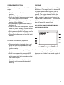
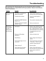
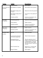
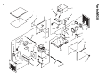
1
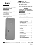
Table of Contents POWER 8KW NATURAL GAS / LP GAS P OW ER Specifications .................................................... 2 Safety Precautions ........................................ 3-5 Introduction .................................................. 6-7 Controller Features ..................................... 6 Hour Meter ................................................. 6 Switches ...................................................... 6 Automatic Fault Shutdown ......................... 6 7-amp Controller Fuse ................................ 6 Circuit Protection ....................................... 6 Starting the Generator Set........................... 7 Auto Start.................................................... 7 Manual Start ............................................... 7 Controller Resetting Procedure .................. 7 Installation ..................................................... 8-9 Voltage Connection Diagram ...................... 8 Typical Installation ..................................... 9 Operation................................................... 10-13 Stopping Procedure .................................. 12 Fuel System .............................................. 12 Battery ...................................................... 12 Storage Procedure..................................... 13 Cooling ..................................................... 13 Schematic ........................................................ 14 Trouble Shooting ....................................... 15-16 Service Schedule ............................................ 17 Parts ........................................................... 18-21 Enclosure ............................................. 18-20 Notes ......................................................... 21 Control Box ......................................... 22-23 Warranty ........................................................ 24 8KW Engine Serial #___________ Engine Model #___________ Manual Part #: 25109 Revised Date: 1/8/01 B 918 Knopf Road Berlin, Wisconsin 54923 Ph: (920) 361-4442 Fax: (920) 361-4416 CALL OUR PARTS HOT LINE: Parts orders placed by 3:30 p.m. can be shipped the same day by Regular or Overnight UPS. 1-800-926-9768 1 Magnum Power Generator Specifications Generator Rated Maximum Power Capacity Rated Voltage Rated Maximum Load Current at 120/240 volts Driven Speed of Rotor Rotor and Stator Insulation Rated AC Frequency Recommended Transfer Switch Switch Amperage Rating 8,000 Watts (8kW) 120/240 volts, 1∅ 66.7/33.3 amps 3600 RPM Class “F” 60 Hz @ 3600 RPM #25033 100 or 200 amps, 250 volts Engine Make Model Type of Engine Number of Cylinders Rated Horsepower (LP Gas) Rated Horsepower (Natural Gas) Displacement Valve Arrangement Ignition System Starter Air Cleaner Oil Filter Crankcase Oil Capacity Briggs & Stratton 354447 Type 0044E1 4-Cycle, air cooled 2 16 HP @ 3600 RPM 13 HP @ 3600 RPM 570cc Overhead Valves Solid State 12 volt DC w/Alternator Dual Element Full Flow Cartridge 1.5 U.S. Quarts (Consult engine operators manual for oil recommendations) Dimensions Generator Length Width Height Weight 35 3/8” (898mm) 24” (609mm) 29” (736mm) 387 lbs. (175 kg) Fuel Consumption Generator Using LP Gas Using Natural Gas 2 2.2 Gallons / hour 150 Cubic ft. / hour Safety Precautions and Instructions For safe installation, operation, and maintenance of this product, read and follow the procedures and safety precautions detailed within. Failure to comply with installation procedures, operation procedures, or safety precautions may result in personal injury and/ or property damage. Store this manual in a safe place for future reference. ACCIDENTAL STARTING WARNING DANGER Danger indicates a possible hazardous situation that will cause extreme personal injury, death, or substantial property damage. WARNING Warning indicates a possible hazardous situation that can cause extreme personal injury, death, or substantial property damage. Accidental starting can cause serious injury or death. Before doing any work on the generator set, turn master switch to the OFF position, and remove the battery cables from the battery (negative terminal first). This will prevent the generator start mechanism in the automatic transfer switch from starting the generator set. When the work is complete reconnect the positive terminal first. BATTERY WARNING CAUTION Caution indicates a possible hazardous situation that will or can cause minor personal injury or property damage. NOTICE Notice indicates information pertinent to maintenance, installation, or operation. Though the information is important to the reliability of your generator set, it is not hazard related. Batteries contain sulfuric acid, which can cause severe injury or death. Sulfuric Acid can cause permanent eye damage, burn flesh, and eat holes in clothing. Protective eye wear and clothing are necessary when working on or around the battery. If acid splashes in or around the eyes, flush with water for 15 minutes. Seek immediate medical attention. 3 MOVING OR ROTATING PARTS EXPLOSION WARNING Explosions can cause severe injury or death. The Battery and Trickle Charge should be stored in a well-ventilated area away from explosive fumes. WARNING Moving or rotating parts can cause sever injury or death. Keep hands, hair, feet, clothing, jewelry, and test leads away from moving parts. NEVER operate the generator set without the guards and electrical enclosures in place. ENGINE FUEL SYSTEM ELECTRICAL SHOCK WARNING Fire can cause severe injury or death. Do not smoke or permit others to smoke in the vicinity of the fuel line, carburetor, fuel filter, fuel pump, or other sources of fuel (vapor or liquid fuels). The fuel lines and connections should all be professionally checked for leaks at the point of installation. Periodic inspections of the fuel lines and connections is recommended. Use a soap solution to identify any possible leaks. Do not use a solution containing ammonia or chlorine, neither produce bubble formations. 4 WARNING The possibility of electrocution is present whenever electricity is present. Open main circuit breakers to all power sources before performing maintenance to the generator set. The generator set should be grounded during installation. Only a trained professional should perform high voltage tests. The guidelines set forth by the equipment manufacturer need to be followed. Failure to follow the set guidelines can result in damage and/or future generator failure. NOISE CAUTION Prolonged exposure to sound levels in excess of 85 DBA can cause permanent hearing loss. Hearing protection should be worn when near an operating generator set. Do not operate generator set without functional exhaust system. EXHAUST SYSTEM WARNING Hot parts can cause severe injury or death. During operation, the exhaust system will reach temperatures that can ignite combustible materials and cause severe burns. Make sure that the exhaust system is free of combustible materials at all times. WARNING WARNING ,,,,,,,,,,,, ,,,,,,,,,,,, ,,,,,,,,,,,, ,,, ,, ,,,,,,,,,,,, ,,, ,, ,,,,,,,,,,,, ,,, ,,,, ,, ,,,, ,,,, Before attempting any maintenance to the generator set, make sure that the generator set has had time to properly cool down. Carbon monoxide gases can cause extreme nausea, fainting, or death. NEVER operate the generator set inside without safely venting the exhaust outside. When installing the generator set outside, insure that the exhaust system is not venting into an enclosed area where the carbon monoxide gases can gather. Carbon monoxide is a colorless, odorless, tasteless gas that can cause severe injury or death with minimal exposure. 5 Introduction CONTROLLER FEATURES AUTOMATIC FAULT SHUTDOWNS The generator controller was specifically designed for standby applications. It is equipped with monitoring and shutdown capabilities to ensure proper function. Any tampering or adjustments to the controller can cause serious injury and/or death. If the generator set fails to start after 5 attempts, the overcrank shutdown will be activated. The engine is also equipped with an oil pressure switch that will activate the low oil pressure shutdown if the oil pressure drops, and a high temperature switch that will activate shutdown. These errors are signified by a solid RED light on the control panel. ♦Hour meter ♦Switches • AUTO/OFF-RESET/MANUAL ♦Automatic Fault Shutdowns • Overcrank • Overspeed • Underspeed • Low Oil Pressure ♦ 7-amp Controller Fuse 7-AMP CONTROLLER FUSE A 7-amp fuse protects the generator controller from damaging electrical surges. In the event that the generator shuts down unexpectedly or without apparent cause, check the controller fuse first. HOUR METER CIRCUIT PROTECTION The hour meter serves two purposes: it tallies the hours of operation, and it serves as a bench mark for your maintenance schedule. A line circuit breaker has been sized for generator output in the event of an overload or a short circuit. If the generator set circuit breaker trips, reduce the load, and switch the breaker back to the ON position. The generator set will continue to run even if the circuit breaker is in the OFF position, but there will be no output voltage. SWITCHES The AUTO/OFF-RESET/MANUAL switch is a three-position toggle switch. 6 STARTING THE GENERATOR SET Before starting the generator, the following procedures should be performed to ensure peak performance; • Check engine oil level, it should be at or near the full mark. • Visually inspect engine, generator, and exhaust system to ensure that they are free from any obstructions or debris that may block air flow or possibly ignite from contact with hot engine components. The engine compartment should be free of any objects foreign to its design. • Inspect the battery cables to ensure that they are tightly connected and free of corrosion. • Maintain a clean air filter to prevent contaminants from entering the engine. AUTO START For remote starting, follow the pre-start checklist, and place the AUTO/OFF-RESET/ MANUAL switch in the auto position. When the controller receives the start command from the transfer switch, the starting procedure will begin. If the generator fails to start, the transfer switch will automatically return to utility power. Refer to the troubleshooting section of this manual. The controller will start the engine if either: 1.) The control switch is in the MANUAL position or 2.) The control switch is in the AUTO position and the remote start contacts are closed. Before attempting to start the engine, the speed input is checked. If it is determined that the engine is already running, only the fuel solenoid is energized. Otherwise, the controller will attempt to start the engine by engaging the fuel solenoid and the starter relay. The speed input is monitored to determine if the engine starts. If the starting speed is detected, the starter relay is disengaged and normal monitoring is begun after the startup delay period of 10 seconds. This delay allows oil pressure to be established and allows the engine speed to stabilize. Cranking will continue for 10 seconds if the engine does not start. After this time, the fuel solenoid and the starter relay are disengaged for a rest period of 10 seconds. After the rest period, another crank attempt is performed. After five unsuccessful attempts, the controller will issue an OVERCRANK shutdown fault. If this occurs follow the guidelines in the troubleshooting section of this manual. MANUAL START After completing the pre-start checklist, place the AUTO/OFF-RESET/MANUAL switch in the manual position. The engine controller will begin the starting procedure detailed above. If the generator does not start, return the switch to the off-reset position for the duration of 10 seconds and return the switch to the manual position. If the generator completes a second starting cycle without successfully starting, refer to the troubleshooting section of this manual. CONTROLLER RESETTING PROCEDURE The following procedure must be used to reset the controller, after a fault condition. 1. Place the toggle switch in the OFF/RESET postion. 2. Switch the circuit breaker to the OFF position, and disconnect the load. 3. Correct the fault condition (Refer to fault shut downs). 4. Place the toggle switch in the MANUAL or AUTO position for startup. 7 Installation The Magnum Power 8KW standby generator was not designed as a do-it-yourself project. Only qualified professionals should install the generator in compliance with the United States National Electric Code (NEC), state and local codes, and Occupational Safety and Health Administration (OSHA). combustible material. If the installation location is made of combustible material, the qualified installation professional must take the necessary measures to insulate the generator from the combustible materials. •Decide what your critical loads are, and choose the proper isolation method. •Choose which fuel type you would like to use for the generator and locate the generator as close as possible. (All fuel lines need to be checked for leaks) It is equally important to carefully plan the installation in conjunction with the qualified installation professionals. Things to take into consideration are: •Location of the generator indoor or outdoor. (Proper exhaust ventilation is necessary and the area should be in a place that is not prone to flooding) •The generator must be mounted on a solid foundation, a 3” cement slab is recommended along with anchoring the unit to the foundation with bolts. Allow 3 feet of clearance around the entire generator for maintenance, service, & exhaust gases. •The location must provide adequate airflow for engine and generator cooling. To prevent damage to the generator set caused by overheating, ensure that all air inlets and outlets are free from obstruction at all times. •The transfer switch must be sized appropriately to handle the ampere rating. •The generator’s voltage and phase ratings must be in accordance with the utility supply and load circuit voltage and phase rating. •The generator should never be installed on VOLTAGE CONNECTION DIAGRAM Use the following diagram (see diagram A) and text to help in the generator set voltage connection procedure. Connect 1-phase generator sets to either a 110-120 volt or 200240 volt configuration. Never connect Leads L1 and L2 together. S t a t o r L e a d s T4 T3 L0 T2 GRD L2 L1 T1 Line Side Load Side To Get 120VAC @ 60Hz 120VAC @ 60Hz 240VAC @ 60Hz Diagram A 8 Use L1-L0 L2-L0 L1-L2 Typical Installation Normal Only Distribution Circuits Typical Emergency Distribution Circuits Local Utility Company LOAD Electric Utility Power NORMAL P OW E R 8KW EMERGENCY Emergency Engine Generator 9 Operation CONTROL PANEL COMPONENTS MANUAL START AND TRANSFER 1. AUTO/OFF-RESET/MANUAL Switch: Set the toggle switch to the AUTO position for automatic operation. Set toggle switch to the MANUAL position to crank and start the generator engine. Set switch to OFF position to shut down an operating engine. With OFF or MANUAL selected, automatic operation will not be possible. To start the engine manually and transfer load circuits to the EMERGENCY (standby) power source manually, proceed as follows: 1. Check for proper manual operation of the automatic transfer switch, using a manual handle. WARNING With this switch set to AUTO, the engine can crank and start suddenly without warning. Such automatic start up normally occurs when utility source voltage drops below a preset level. To prevent possible injury that might be caused by such sudden starts, set switch to OFF before working on or around the unit. 2. 7-Amp Fuse: Fuse protects the control panel’s DC control circuit against electrical overload. If the fuse has failed open due to an overload, the engine cannot crank and start. When replacing the fuse, use only an identical 7-amp replacement fuse. 3. Main Breaker: Protects the generator against electrical overload. With the breaker in the OFF position, the generator has no output. 4. Fault LED: Help to trouble shoot problems. a. If the generator is placed in the auto position, the LED light will flash green. b. If the generator is cranking over, it will be a solid yellow. If the generator does not start, the LED will flash yellow until the next cranking attempt. c. The red light is for all fault conditions. The number of flashes signifies what fault has occurred: -One Flash: Oil Pressure -Two Flashes: Over Crank -Three Flashes: Over/Under Speed -Four Flashes: Battery Voltage 10 Do not try MANUAL operation of the transfer switch until all power supplied to the switch has been positively turned OFF. Failure to turn OFF the supplied power may result in an extremely dangerous and potentially lethal electrical shock. 2. After verification that transfer switch operates manually, actuate the transfer switch main contacts to the UTILITY position, i.e., LOAD terminals connected to the utility power supply. 3. Turn ON the utility power supply to the transfer switch with whatever means provided. With an AC voltmeter, verify that correct load voltage is available at transfer switch main contact, terminal lugs N1 and N2. 4. On the generator control panel, set the AUTO/OFF-RESET/MANUAL switch to the OFF position. 5. Turn OFF the utility power supply to the transfer switch, with whatever means provided. 6. Set the generator’s main circuit breaker to the OFF position. 7. Turn off all electrical loads. Initial testing and adjustment should be conducted with the generator at “no-load.” 8. To start the generator engine manually, set the AUTO/OFF-RESET/MANUAL switch to the MANUAL position, engine starts. Let the unit stabilize and warm up for a few minutes. 9. Set the main circuit breaker on the generator to the ON position. 10. With an accurate AC voltmeter, verify that correct rated voltage and frequency are being supplied to transfer switch terminals E1, E2, and neutral. a. Do not proceed until generator output frequency and voltage are correct. b. If AC frequency is not within 60-62 Hz at no-load, contact authorized service technician. DO NOT attempt to adjust the governor. Only qualified service facilities should adjust the governor. Excessively HIGH operating speeds are dangerous and increase the risk of personal injury. LOW speeds impose a heavy load on the engine when adequate engine power is not available and may shorten engine life. Correct rated frequency and AC voltage are supplied only at the proper governed speed. Incorrect AC frequency and/or voltage may damage some connected electrical load devices. IT IS RECOMMENDED THAT ONLY QUALIFIED SERVICE TECHNICIANS ADJUST THE ENGINE GOVERNOR. NOTE: On units connected for 240 volts, 1 phase output, line-to-line voltage at 62 Hz should be 240-250 volts. Take these initial readings with the generator running at no-load. IMPORTANT: DO NOT PROCEED UNTIL NO LOAD FREQUENCY AND VOLTAGE ARE CORRECT. 11. Verify that all utility power has been turned OFF to the transfer switch with whatever means provided. Then, manually actuate the transfer switch main contacts to the STANDBY position, i.e., LOAD connected to the GENERATOR. 12. Turn ON electrical loads that almost equal the generator’s wattage amperage capacity. With an AC frequency meter, check frequency at transfer switch terminals E1 and E2. With generator under load, frequency should not drop below 58 Hz. 13. Let the generator run under load for at least 20-30 minutes. Check for unusual vibration, noise, high temperature, and other indications of abnormal operation. MANUAL RETRANSFER AND SHUT DOWN Electrical loads may be retransferred back to the utility power and the generator can be shutdown as follows: 1. Verify that utility power supply to the transfer switch has been positively turned OFF, using whatever means provided (such as the utility main line circuit breaker). 2. Set the generator’s main circuit breaker to its OFF position. 3. Let the generator engine run at no-load for several minutes to stabilize internal unit temperatures. 4. On the generator control panel, set the AUTO/OFF-RESET/MANUAL switch to OFF. Wait for engine to come to a complete stop. 11 5. With the manual transfer handle, move the switch’s main contact back to the utility power position, thereby, reconnecting the utility power supply. 6. Turn ON the utility power supply to the Transfer Switch, using whatever means provided (such as a utility main line circuit breaker). The utility power source now powers the loads. 4. If the utility source voltage is restored, above the preset level, the transfer switch monitors the voltage for a period of time. After this time the switch retransfers load circuits back to the utility power source. 5. After load circuits are retransfered, the engine will go through its cool down procedure before shutting down. AUTOMATIC OPERATION FUEL SYSTEM To set the system for fully automatic operation, proceed as follows: Either Natural Gas or LP gas can fuel the genset. The genset is equipped with an electric fuel solenoid. The solenoid will adjust for either fuel type with a flip of a switch. A toggle switch on the back side of the control box allows you to choose the desired fuel type. Place the switch to NG for natural gas or LP for LP gas. 1. Check that load circuits are connected to the utility power supply. 2. Set the AUTO/OFF-RESET/MANUAL switch to the AUTO position. 3. Set the generator main circuit breaker to its ON position. Note: Fuel pressure coming into fuel shut off valve should be adjusted to 11-14 inches of water. AUTOMATIC OPERATING SEQUENCE The automatic operation is controlled by the automatic transfer switch. For a more exact description of automatic operating sequence, see Transfer Switch Instruction Manual. The sequence of automatic operation is briefly described as follows: 1. Should the utility source drop below a preset level, a delay timer starts. 2. After the delay time, the transfer switch sends a signal to the engine remote contacts to start. Note: The delay timer is provided to override momentary outages & prevent nuisance starting of the genset. 3. The transfer switch senses the voltage of the emergency source. When the emergency source reaches a preset level, transfer delay timing begins. When this time is completed, the load circuits are transfered to the emergency source. 12 BATTERY It is recommended that a 12-volt battery with a minimum of 450 cold cranking amps be used for the genset. The climate will be a major factor in deciding the appropriate battery. If the temperature dips below 0- F for extended lengths of time, a more powerful battery may be necessary. Consult your local dealer/ distributor for assistance. If the genset is not run on a regular basis, it is recommended to use an external battery charger to sustain full charge. Follow the safety precautions in the beginning of this manual when servicing the battery. Batteries contain sulfuric acid, which can cause permanent eye damage, burn skin, and eat holes in clothing. Battery gases can cause an explosion, which can cause severe injury or death. Take extreme care when removing and replacing battery terminals, reversed connections can cause severe damage to the genset. STORAGE INSTRUCTIONS COOLING Recommended storage procedure for the engine: The genset is powered by an air cooled Briggs & Stratton V-Twin engine, and it is imperative for proper operation and longevity, that the cooling system works as designed (see diagram B). The engine draws in air from the engine side, and blows the air across the engine, exhaust, generator end, and out the opposite end of the enclosure. The enclosure for the genset was designed to take in and blow out a specific amount of air. • Run the engine for 5 minutes to warm the engine. • Drain oil from the crankcase. • Refill with fresh oil of recommended grade (see chart page 3 engine manual). • Remove spark plugs and pour 1oz. of engine oil into cylinders. • Replace spark plugs and crank slowly to distribute oil. • Clean dirt and chaff from cylinders, cylinder head fins, blower housing, rotating screen and muffler (see page 7 engine manual). • Start generator, shut off fuel supply, and let the engine stop from lack of fuel. • Disconnect fuel source and cap fuel inlet to engine. ANY OBSTRUCTIONS TO THE AIRFLOW CAN CAUSE SEVERE ENGINE AND GENERATOR DAMAGE FROM OVERHEATING. POWER 8KW Enclosure and Generator preparation: • Disconnect battery terminals, clean, and wrap with non-absorbent adhesive tape. • Remove dirt and dust from outside and inside of cabinet. • Remove any objects foreign to the genset’s design. • Store in a clean and dry area, but NOT near a stove, furnace, or water heater which uses a pilot light or any device that can create a spark. • It is also recommended to place a tarp over the entire unit to prevent dust and dirt build-up. Diagram B It is recommended to place the generator in an open area with a minimum of three feet of clearance on all sides for an ample supply of fresh air. 13 A GRY ORG BLK RED - RED ORG DRK BRN RED RED D.C. 4 AWG RED RED BLK VIO RED RED ORG RED RED 4 AWG GRY SWITCH, DPDT STARTER SOLENOID GRY Added trickle charger and Diode BLU LT BRN GRD RS ATS CONTROL BOARD CRANK FUEL BATT BATT + BLK RED YEL RED RED BLK 12/18/00 CONTROL BOX GROUNDING STUD MANUAL OFF AUTO 7 AMP FUSE RED BLK BLK DRK BRN LED STARTER MOTOR BLK YEL HOUR METER YEL ORG BRN BLU RED BLK L1 BLK T1 A B C D E F T3 LT BRN L2 BLK T4 T2 GENERATOR RED REGULATOR/ RECTIFIER BLK GRN ENGINE 86 YEL FLYWHEEL STATOR ASSY 7 1 12 11 10 9 8 6 5 4 3 2 REMOTE START CONNECTIONS 7 1 12 11 10 9 8 6 5 4 3 2 GRY BRN VIO BRN BLK 85 BLK BLK FUEL VALVE CUSTOMER CONNECTIONS L1 L2 L0 L0 GRD ENGINE GROUNDING STUD GRY VIO VIO RED BLK YEL ORG CIRCUIT BREAKER BLK BLK GENERATOR GROUNDING STUD WHT BRN NO BLK COM BLK 30 SWITCH SPST GRN 10 GA. VIO BLK 14 87 RED RED BLK YEL BLK A JCJ BATTERY 12V 4 AWG BLK GRY NTS 10/17/00 RED BLK - + 25475 Schematic - MG8/RE/Q RED BLK TRICKLE CHARGER TRANSFER SOLENOID OIL SWITCH Point to Point Wiring Diagram Troubleshooting When problems arise with the generator set, don’t overlook the obvious solutions. More times than not, a simple solution will fix your problem. Call your local dealer/distributor for assistance. Problem Possible SourceSolution Genset does not turn over. Poor battery connections or cables are reversed. Inspect cable connections for corrosion and correct placement. Controller fuse is blown. Inspect fuse and replace if necessary. AUTO/OFF-RESET/MANUAL Switch is off. Place switch in desired position. Defective AUTO/OFF-RESET/ MANUAL Switch. Perform a function test. Fuel source. Check to insure that the correct fuel source has been selected. Also, inspect fuel lines to insure that the generator set is receiving the appropriate level of fuel pressure. Primary and Secondary Regulators. Perform a function test. Weak Battery. Check voltage and recharge or replace. Fouled spark plugs or loose connection. Inspect spark plugs, and replace if necessary. Check for tight connect to spark plug wire. Engine timing off. Service engine. Low oil pressure shut down. (LED will be steady Red) Check oil level and pressure. If both are within the recommended levels, check controller for function. Genset turns over, but does not start, or starts and runs with difficulties. 15 Problem No AC output from generator. Low output (Frequency) High output (Frequency) Generator stops suddenly. 16 Possible SourceSolution Engine problems. Service engine. Main Breaker in off position. Place breaker in the on position. Main Breaker tripping from overload. Reduce the load on the generator. Main Breaker tripping from a short circuit. Find the short in the system and correct. Generator problem. Contact your local dealer or distributor for assistance. Overloading generator. Reduce the load on the generator. Faulty capacitor. Replace capacitor. Generator problem. Contact your local dealer or distributor for assistance. Faulty capacitor. Replace capacitor. Generator problem. Contact your local dealer or distributor for assistance. No Fuel. Check fuel source. Low oil pressure shutdown. (LED will be steady Red) Check oil level and pressure. Overcrank shutdown. (LED Will be steady Red) Place the controller in the off position for 30 seconds and return to desired position. If the automatic shut down occurs again, check the generator system and controller. Blown Controller Fuse Replace fuse. If it blows again, inspect controller for faults. Engine Problems. Service engine. Service Schedule DUSTY OR DIRTY OPERATING CONDITIONS If the generator set operates under these conditions, use dry compressed air to blow out the generator. With the generator set running, direct air through the slots at the engine end of the generator set. ENGINE SERVICE Perform routine maintenance at specified intervals as documented in the Briggs & Stratton Engine Manual supplied with this generator set. TUNE-UPS Have the generator set tuned-up by an authorized distributor. Tune-ups will improve performance and maintain reliability of the generator set during its long lasting service life. SCHEDULED SERVICE Perform scheduled service at every scheduled interval to ensure satisfactory operation of the generator set. If rough operation, lack of power, or excessive oil use is apparent, have an authorized distributor service the generator set. Serious generator set problems can be prevented with immediate action. Service Schedule Component 5 Hours or Daily Weekly Frequency 25 Hours 50 Hours or Every or Every Season Season 100 Hours or Every Season Yearly Fuel Inspect flexible lines and connections Check solenoid valve operation Cooling Air cleaner Louvers Exhaust System Inspect Insulation Check Muffler bracket Inspect Muffler box for fire hazards Engine Check oil level Change oil ♦ P Change oil filter ♦ P Change air cleaner pre-cleaner Change air cleaning cartridge Clean cooling system PP PP Replace or clean spark plugs Replace in-line fuel filter (Not supplied with unit.) Check valve lash Clean combustion chamber deposits Electrical System Inspect battery and battery tray (Not supplied with unit.) Clean and tighten battery terminals ♦ Change oil after first 8 hours, then after every 50 hours or every season. P Change oil every 25 hours when operating under heavy load or in high temperatures. PP Clean more often under dusty conditions or when airborne debris is present. Replace air cleaner parts, if excessively dirty. 17 Parts MG8 18 7 6 1 4 2 8 3 12 41 13 15 42 9 40 5 36 34 10 25 38 14 11 16 10 17 18 35 39 24 20 23 37 32 33 31 28 16 19 30 29 26 16 22 27 21 Parts MG8 Item # Part No. Qty. 1 2 3 4 5 6 7 8 9 10 11 12 13 14 15 16 17 18 19 20 21 22 23 24 25 26 27 28 29 30 31 32 33 34 35 36 37 38 39 40 - 25049 25210 25053 25052 25209 25115 25113 25215 25056 25085 25061 25212 25069 25050 25101 25068 25211 25099 60199 25072 25073 25074 25098 19300 25080 19280 25081 25060 25045 25406 19041 25070 25051 25067 25111 25110 25082 25058 25213 25214 25282 25208 25086 19453 1 1 1 1 1 2 1 1 1 2 1 1 1 1 1 4 1 1 2 1 1 1 1 1 1 1 1 1 1 1 1 1 1 1 1 1 1 1 1 1 1 1 1 2 Description Panel, Top Insulator, Top Panel Panel, Back Access Panel, Back Insulator, Back Panel Bracket, Muffler Assy, Mufller Box Insulator, Battery Box Box, Battery Grommets, Rubber Generator Insulator, Generator Duct, Generator Panel, Right Side Bracket, Generator Mount Mount, Isolation Insulator, Door Assy, Front Door (Includes Door Pins) Door Pin Handle, Small Locking ‘T’ Lock, Cam Keys Weldment, Panel - Base Cap, Oil Drain Drain, Oil Line - 20” Long Valve, Ball 90° Fitting, Oil Drain Engine, Vanguard V-Twin LP/NG Bracket, Upper Engine Mount Bracket, Lower Engine Mount Clip, Spring Holder Duct, Engine Panel, Left Side Regulator, Secondary - Demand Nipple, 3/4” x 2” Elbow, 90° Street - 3/4” NPT Fitting, 90° - 3/8” MNPT both ends Valve, Fuel Solenoid - 12V DC Insulator, Control Box Back Insulator, Control Box Bottom Assy, Control Box Complete Insulator, Engine Duct Hose, Fuel Line 1/2” FNPT one end - 20” Long Clamp, Worm 11/16” OD Hose 19 Parts MG8 Item # Part No. Qty. 41 42 25059 15627 25065 25064 25057 25283 25120 1 5 1 1 2 1 1 Not Shown Not Shown Not Shown Not Shown Not Shown 20 Description Muffler, Residential Grade Clamp, Tubing .625 Heavy Duty Rod, Coupling Flange, Coupling Gasket, Muffler Harness, Engine - Wiring Harness, Generator - Wiring Notes 21 Parts MG8 2 3 4 2 6 5 1 7 5 9 9 8 10 9 22 Parts MG8 Item # Part No. Qty. 1 2 3 4 5 6 7 8 9 10 65038 25077 25276 25079 25078 25048 15085 25112 25083 65039 25121 1 1 1 1 1 1 1 1 1 1 1 Not Shown Description Breaker, Circuit 40 Amp 2-Pole Switch, Toggle - NG/LP Conversion Board, Controller Strip, Terminal Switch, Toggle - Auto/Off/Manual Box, Controller Gauge, Hourmeter LED, Mode Indicator Holder, Panel Mount Fuse Fuse, 7 Amp Grommet 23 ONE YEAR or TWO THOUSAND (2000)-HOUR LIMITED WARRANTY Your Magnum Power Standby Generator was manufactured, assembled, tested, and inspected by experienced craftsmen. Magnum Products, Inc. warrants the generator set for a period of one year or 2000 hours, which ever occurs first. The following conditions must be met: Ø You must be the original consumer. Ø Installation and start-up procedures were performed by an authorized professional in accordance with the guidelines published in the operations manual. Ø Maintenance schedules and operation procedures detailed in the operations manual were followed. Ø Malfunctions or damages were not a result of misuse, unreasonable use, acts of nature or repair and service work performed by an unauthorized person. ITEMS NOT COVERED BY WARRANTY: Ø Maintenance items i.e. spark plugs, air filter, fuses, adjustments, LED’s, etc. Ø Any rental of the standby generator will void warranty. Ø Labor charges for troubleshooting problems will only be covered if a problem is attributed to defective Magnum materials or craftsmanship. Ø Any engine fluids that are necessary for normal operation of the generator set. Ø Any charges related to the starting battery or the installation of the starting battery. Ø The initial installation and start-up charges. Ø Damages caused from the following list will not be covered under warranty: Ø Failure to exercise the generator under load. Ø Use of unauthorized service parts, incorrect oil type, or inappropriate oil level. Ø Failure to keep air intake and cabinet free of obstructions and debris. Ø Failure to properly maintain a clean air filter. Ø Failure to maintain the maintenance schedule detailed in the operations manual. At the point of purchase, a warranty card must be filled out and returned within 45 days to Magnum Products, Inc. If the card is not filled out and returned, the ship date from the factory will be used as the start date for the warranty period. Magnum Products, Inc. will not be liable for any incidental or consequential damages of any kind without prior authorization from the warranty department. This warranty is exclusive to Magnum Products, Inc. and nobody is authorized to extend the warranty in any way. *Engine is warranted for 2 years by Briggs & Stratton. See engine manual for full details. For warranty service, please call 800-926-9768, or write Magnum Products, Inc., 918 Knopf Rd., Berlin, WI 54923. 24