1
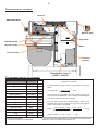
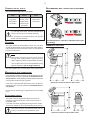
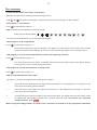
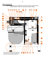
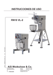
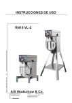
OPERATING INSTRUCTIONS 072012 ORDER NO.: 00242_VL2 GB Original instructions RN10 VL-2 A/S Wodschow & Co. Industrisvinget 6 DK-2605 Brøndby Denmark Phone: +45 43 44 22 88 Telefax: +45 43 43 12 80 www.bearvarimixer.com [email protected] 2 Contents: General: . ..................................................................................................................................................................... 2 Safety: . ..................................................................................................................................................................... 2 Installation of new mixer:.................................................................................................................................................. 2 Examples of power connections:....................................................................................................................................... 3 VL2 control panel - survey of various operating situations:............................................................................................. 3 Operation of the mixer:..................................................................................................................................................... 4 The Remix function:........................................................................................................................................................... 5 Change of fixed speeds:.................................................................................................................................................... 5 Reset of timer:.................................................................................................................................................................. 5 Overload: . ..................................................................................................................................................................... 5 Procedure in case of overload:........................................................................................................................................ 5 Recommended maximum speeds:........................................................................................................................................... 5 Construction of the mixer:................................................................................................................................................ 6 The maximum capacity of the mixer:.................................................................................................................................... 6 Correct use of tools:....................................................................................................................................................... 7 Cleaning: . ..................................................................................................................................................................... 7 Maintenance and lubrication:............................................................................................................................................ 7 Attachment drive:.............................................................................................................................................................. 7 Recommended max. speeds for attachment drive:............................................................................................................... 7 Dimension sketches:........................................................................................................................................................... 7 VL-2 control, error codes and possible solutions:.......................................................................................................... 8 Test programs:................................................................................................................................................................. 9 Service instructions:....................................................................................................................................................... 10 Cabling diagram:............................................................................................................................................................. 14 Electrical diagram:......................................................................................................................................................... 15 Handle for bowl lift can be mounted in both sides of the mixer:..................................................................................... 16 General: In case of complaints, please contact your supplier. The guarantee does not cover faults resulting from faulty operation, overloading and lacking observance of directions of maintenance. It should be checked that all loose parts are delivered with the mixer such as bowl, tools and intermediate pieces. To the attachment drive should only be connected attachments produced by A/S WODSCHOW & CO. Safety: If the mixer is not connected to earth there is danger of injury. It must be ensured that the cable used for connecting the machine to power, meets the standard of the country where the machine is installed! – see also “Connection to power” table. Use 4 M6 bolts with a length of 90 mm + the thickness of the table top, see drawing page 10 If the mixer is placed on a bench stand, it can be placed direct on the floor. Foundation bolts in the floor are recommended. Intermediate pieces can be inserted under the mixer’s feet, if the floor is not completely even. Connection to power: Check that the voltage and frequency printed on the machine sign is correct compared to the place of installation. The machine sign is placed at the top of the back of the mixer. When the mixer is connected, use phase + neutral + earth or phase + phase + earth. In both cases it is important that the voltage between the two live pins is in accordance with the machine sign. (See examples on page 3). The mixer must be connected to earth! The constant noise level of the work place of the operator is lower than 70 dB (A). The mixer is designed for manufacture of products which do not during processing cause reactions or emit substances which may be detrimental to the user. Putting your fingers in the bowl while the mixer is running may cause injuries. Installation of new mixer: Installation and securing: If the mixer is placed on a table, it must be bolted on to the If not, it will cause missing function of EMC filter as well as risk of damaging the frequency converter. • The mixer must only be connected to single phase power with earth. • A two-pin plug with earth is to be used. Alternatively two conductors and earth from a 3-phase power supply. • The mixer must be protected by a differential switch. • The machine is secured through a 5A fuse. The fuse is built into the cable plug which is placed at the bottom of the back of the mixer. To this comes a 10A fuse which is mounted in the frequency converter, see “Service instructions” page 10. 3 VL2 control panel - survey of various operating situations: The following pictures show various operating situations and corresponding explanation: 2 1 Emergency stop is activated - there is no light in the display. If the red diode at is flashing, the mixer has stopped because the safety circuit has been interrupted, either because the bowl arms have been lowered or the safety guard has been opened. The mixer is connected to power and is ready for start - flashing of the green diode at will show that! It is possible to set a start speed by pushing one of the fixed speeds or , before is pushed. When is pushed, the mixer will start in minimum speed. Operating time is stated by pushing or . A program is run by first pushing and thereafter the wanted number, e.g for program No. 1. 4 3 The mixer is running and a speed has been chosen four diodes on the speed indicator are alight. The speed can be changed by pushing one of the buttons for the four fixed speeds or or . The mixer can be stopped without reset of the timer, by pushing or by opening the safety guard. The mixer is restarted by pushing . has been pushed - yellow diode at is flashing. The mixer is started by pushing . The timer will start again and the speed is running up to the chosen speed. If is pushed, the timer is reset and the mixer will not start, but is ready for start - green diode at will flash (see picture 2). Examples of power connections: Voltage at the installation: 50/60 Hz The machine sign Power: Phases x voltage With neutral Earth Voltage Phases 1 x 220-240V Neutral yes 230V 1 2 or 3 x 220-240V - yes 230V 2 or 3 x 380-415V Neutral yes 230V 2 or 3 x 380-480V - yes 2 or 3 x 110-220V Neutral 1 x 100-120V 3 x 100-120V Use Use neutral earth yes yes 2 - yes 1 yes yes 380-480V 2 - yes yes 100-110V 1 yes yes Neutral yes 100-110V 1 yes yes - yes 100-110V 2 - yes Remarks Please note that the mixer is able to run without any connection to earth, but this causes a reduced functionality of the EMC-filter due to lack of leakage to earth. Of functional and safety reasons, the machine should be connected to earth!. 4 Operation of the mixer: Text field (timer) Fixed speeds Speed indicator Time down Speed up REMIX-function Time up Start/Stop Speed down Emergency stop Pause Indication of operation time: Before starting the mixer: Mount the required tool in the bayonet shaft. Place the bowl in the bowl arms and raise it to its working position by means of the handle for bowl lift. Close the safety guard. The mixer is ready for start. Before starting the mixer, an operation time for the mixer can be chosen by pushing or . The operating time will be shown in minutes and seconds in the timer field between and . Start the mixer: The maximum operating time is 60 minutes. Push to start the mixer. Inspection of the ingredients during operation: Push to increase the speed. Push to reduce the speed. Or push speeds. , , or If it is wished to stop the mixer without reducing operation time and speed, push . The mixer will reduce speed and then stop, the operation time will also stop. to choose one of the fixed The speed indicator below the fields mixing speed of the tool. to shows the Four fixed speeds: For quick choice of speed, use the fields to . Field corresponds lowest speed, aprox. 110 RPM. Field corresponds aprox. 212 RPM. Field corresponds aprox. 318 RPM. Field corresponds maximum speed, aprox. 420 RPM. It is now possible to open the safety guard to check the ingredients. Close the safety guard and push , and the mixer will start and will increase the speed to the speed chosen before pushing . The operating time will also be continued. If the bowl is lowered while the mixer is stopped, the operating time is reset, and must be pushed to restart the mixer. For previous users of the old 10 L model, AR10: On the AR10 the speeds 1, 2 and 3 corresponded the below mentioned RPM: Speed 1 corresponded approx. 110 RPM. Speed 2 corresponded approx. 150 RPM. It is possible to change the fixed speeds - see the paragraph „Change of fixed speeds“. Speed 3 corresponded approx. 380 RPM. 5 The Remix function: Reset of timer: The special Remix-function is a shortcut to programming of recipes. While the mixer is operated, all commands are stored, and when a recipe is finished and is pushed, it is possible to store the entire recipe under a program number. The timer can be reset by simultaneously pushing and . If the timer is reset while the mixer is running, the mixer will stop. • There are four program numbers. • A program cannot be deleted, but can be replaced. • The programs are not deleted in case of no power. Overload: Do not overload the mixer. Sticky and heavy doughs may reduce the capacity of the bowl by 75%. The capacity is further reduced if the speed of the mixing tool is increased beyond the re commended values or if a wrong mixing tool is used. Large lumps of fat or cooled ingredients must be cut into small parts before they are placed in the bowl. How to store a program: • First push • Run the entire recipe including pauses and changes of speed. • Push • Store the program as program No. 1 by pushing first and then also continuously, until the total length of the program is shown in the timer field. The timer field will thereafter flash „P1“ three times. . Overload over a long period will cause that the thermal overload relay will switch off the mixer. Follow the description under „Procedure in case of overload“ Procedure in case of overload: . • Push emergency stop • Release emergency stop. • Start the mixer by pushing . How to run a program: • First a short push on and then on . Now „P1“ appears in the timer field and immediately thereafter the total length of the program will be shown. The program is run by pushing . • If the speed or the time is changed, or is pushed when running a program, the program will be left and the mixer must be run manually. • It is possible to open the safety guard while running a program. When the safety guard is closed, the program can be resumed by pushing . • If the program is containing a pause, the mixer will stop and at the same time an acoustic signal is heard. When the operator wants to restart the mixer, push and the program will be resumed. Change of fixed speeds: For the fields and it is possible to change the speed for future mixing jobs. Push or to adjust the speed up or down. If required to store the adjusted speed, push or until two beeps are heard and the diodes of the speed indicator are flashing. The adjusted speed has now been stored in the memory. To return to the factory settings for button and and simultaneously, until a beep is heard. push Recommended maximum speeds: Recommended maximum speeds (factory setting). 6 Construction of the mixer: Bowl lift Attachment drive Machine label Poly V belt Planetary head Bayonet socket Motor Bowl lift arms Frequency converter The maximum capacity of the mixer: Capacities per mix Tool RN10 Egg white Whip 1L Whipped cream Whip 2,5 L Mayonnaise * Whip 8L Herb butter Beater 5 kg Mashed potatoes * Beater/Whip 3,5 kg Bread dough (50%AR) ** Hook 5 kg Bread dough (60%AR) Hook 6 kg Ciabatta dough * (70%AR) Hook 5,5 kg Muffins * Beater 6,5 kg Layer cake base Whip 2,5 kg Meatball mix * Beater 7 kg icing Beater 5,8 kg Doughnut (50%AR) Hook 6 kg * Scraper recommended ** Low speed operation is recommended Transformer, only at x<220V - 240V<x AR = Absorption Ratio (%AR) (Liquid in % of solids) Example: A basic recipe contains 1 kg of solids and 0,5 kg of liquid: This gives AR = 0,5 kg x 100 = 50% 1 kg If for instance it is required to use the maximum capacity of the mixer, the calculated AR = 50% is used for determining the amount of solids and liquid in the dough: If a 10 L mixer is used, and a dough with AR = 50% is to be kneaded, the maximum capacity is = 5 kg. Now the weight of solids in this dough is calculated: Solids = Max. capacity x100 = 5 kg x 100 = 3,3 kg AR + 100 50 + 100 Weight of liquid = 5 kg - 3,3 kg = 1,7 kg Local variations in the characteristics of the ingredients can influence water absorption, volume and baking characteristics, etc. 7 Correct use of tools: Recommended max. speeds for attachment drive: Recommended applications for tools: Whip Beater Hook Cream Cake dough Bread dough Egg whites Butter cream Dark bread Mayonnaise Waffle dough and the like and the like Minced meat and the like Whips should not be struck against hard objects as e.g. the edge of the bowl. This will make the life of the tool shorter due to increasing deformity. For production of mashed potatoes use first the beater and then the whip. Cleaning: The mixer should be cleaned daily or after use. The mixer should be cleaned with a soft cloth and clean water. Sulphonated soaps should be used with caution as they destroy the mixer’s lubricants. Recommended max. speeds for attachment drive (fac tory setting). Dimension sketches: Never use high pressure cleaning for the mixer. Parts made of aluminum should not be used to strongly acidic, highly alkaline or highly salty foodstuffs, which may attack aluminum without coating. Tools of aluminium must not be washed with strong alkaline detergents (pH not bigger than 9.0). The soap suppliers can recommend the correct type of soap. Maintenance and lubrication: If the planetary head is repaired, the toothed wheel and the toothed wheel rim shall be greased with STATOIL Greaseway ALX 82, the needle bearings of the planetary head must not be greased with this type of grease. If the mixer is provided with attachment drive, the gear for attachment drive must be greased with STATOIL Greaseway ALX 82. Dimension sketch for RN10 on floor stand. Do not use any another type of grease than the one stated here. Attachment drive: The mixer can be equipped with attachment drive for mounting of extra accessories, such as meat mincer or vegetable cutter. For further information regarding mounting and use of extra accessories, please see the manual following the accessory. The mixer must be disconnected while the ac cessory is mounted in the attachment drive! Dimension sketch for RN10 table model. 8 VL-2 control, error codes and possible solutions: Error codes and possible solutions: The VL2 control will in case of certain errors show an error code in the display: Too high temperature in the frequency converter. Solution: Switch off the mixer and let it cool down. Wrong voltage of power supply. Solution: Compare the voltage indicated on the machine label with the power supply. The motor has been constantly overloaded for a long period of time. The load has been between 100 - 150% of maximum load. The overload is typically found in case of mixing/whipping tasks with constant load. Solution: Switch off the mixer and reduce the quantity of ingredients in the bowl. Finish the work in a lower speed. Low voltage is periodically noted in the power supply. Solution: The machine’s power supply must be inspected by a technician. Too high temperature in motor. Solution: Switch off the mixer and let it cool down. Reduce the quantity of ingredients in the bowl. Finish the work in a lower speed. Communication break. Cable Connection between the control panel and frequency converter is defective. Solution: Make sure the cable is seated properly in the connectors, replace the cable if it is defective. , and The mixer has been overloaded from work with heavy dough or the like Solution: Reduce the quantity of ingredients in the bowl. if possible, the product may be decomposed into smaller pieces or diluted before the mixer is restarted. Finish the work in a lower speed. Errors that do not cause an error code in the display: The mixer does not start when is pushed, but the timer is counting as normal. There is no error code in the display. Solution: The frequency converter is defective and must be exchanged. See “Service Instructions” page 10 for access to the frequency converter. The mixer does not start when is pushed. There is no error code in the display. Solution: Activate emergency stop and release it again. Now two different codes should be shown in the display. The first code is a small square in top of the first cipher of the display followed by a version code, this is the software version of the control panel. The next code is a small square in bottom of the first cipher of the display followed by a version code, this is the software version of the frequency converter. If no codes are shown or if only the first code is shown, the error can derive from either a defective communication cable between the control panel and the frequency converter, or a defective frequency converter. The mixer is totally “dead”, no light in the control panel. Solution: Check the connection to power supply, if connection and power supply are OK, the error is either a defective communication cable between the control panel and the frequency converter, or a defective fuse in the frequency converter. See “Service Instructions” page 10 for access to the frequency converter. 9 Test programs: To enter the test mode of the mixer, do as follows: Raise the bowl and close the safety guard, push emergency stop. Hold and and release the emergency stop at the same time. Now go through four test programs: Test program 1: Test of fields. Press to activate test program no. 1 OBS. The fields must be activated in the following order: Briefly push the following fields – – – – – – – – – – . The mixer will now automatically run the next three test programs. Test program 2: Test of light diodes. Press to activate test program no. 2 For the first 20 seconds the cipher 2 will flash in the display - the remix memory will be erased. Then the light diodes in the speed indicator will light up one by one, while the other light diodes of the control panel are on. Test program 3: Test of current measurement circuit in the frequency converter. Press to activate test program no. 3 The motor starts and runs for approx. 20 seconds. After the 20 seconds a text is shown in the display, this text will vary and can only be used for testing the function. Test program 4: Test of micro switches in safety circuit. Press to activate test program no. 4 OBS. It is important that the order is kept. The cipher 1 is shown in the display until the safety guard is opened. • • • Open and close the safety guard. The display shall now change to 2. If the display does not change to 2, the micro switch at the safety guard is defective. Raise and lower the bowl again. The display shall now show 3. If the display does not change to 3, the micro switch at the bowl lift is defective. Conclude the test by pushing emergency stop and release it again. The display shall now show version codes for control panel and frequency converter resp., as earlier mentioned under “VL2 control, error codes and possible solutions, error . When running the testprogrammes, no specific order is required. It is possible to run the programmes individually 10 Service instructions: Before a possible repair or adjustment, the power must be switched off by dismantling the connection cable from the power supply. 5A 5B 3B 3C 6D 13C 6 6E 6A 6B 6C 6E 2 13A 13B 5C 3 1A 5 1 4B 4A 4 3A 7 3D 8B 8 8A 11 The mixer is to be bolted on to the table with 4 pcs. M6 bolts. The length of the bolts must be 90 mm + the thickness of the table top. 12B 12 8F 8E 8C 8D 11 1 Take off the rear part by removing the 2 screws (1A) 2 The lid of the mixer can be taken off when the rear part (1) has been removed. Push the lid a little backwards, and lift it free. 3 Take off the operation panel by removing the rubber gasket (3A) and the thumb screw (4A) on the attachment drive. Remove the nut (3B) and loosen the 2 screws (3C). The screws must still grab the two fittings (3D) which are to be lifted up together with the screws. 4 Take out the attachment drive by removing the thumb screw (4A), the rubber gasket (3A) and the operation panel (3). At last loosen the pointed screw (4B) 5 Take off the display print by loosening the screw (5A) and taking off the plastic box (5B). Then loosen the four screws (5C). 6 Exchange the Poly V-belt in the following way: a) Take off the rear part of the mixer (1) and the lid (2). b)Loosen the four screws (6A) holding the motor base (6B). By pushing the base towards the front of the mixer, the belt will be slackened and can be lifted off the motor pulley (6C) and the planetary head pulley (6D). c) Mount the new Poly V-belt by pushing if down over the two pulleys. d) Tighten the Poly V-belt by pushing the motor base towards the back of the mixer. Use a big screw driver or the like to hold the base while the screws are tightened. 6G 6C The motor pulley can be taken off by removing the locking ring (6E), and then using a pulling-off device. 6D Take off the planetary head pulley in the following way: a) Take off the rear part (1), the lid of the mixer (2) and the Poly V-belt (6). b) Screw the pointed screws (6F) out of the pulley. The pulley can now be lifted off the clamping ring. c) To be able to loosen the clamping ring from the shaft, screw one of the pointed screws approx. one turn down into the middle centre hole (6G). The clamping ring can be removed. 6F 6D 7 Take out the motor in the following way: Shut off the power to the mixer, or dismantle the power cable from the connection point. Take off the rear part (1), the lid of the mixer (2), and the Poly V-belt (6). Disconnect the motor cable. Remove the four screws (6A), and the motor base (6B) with motor (7) can now be lifted off the mixer. 9 Take out the frequency converter in the following way: 8 9 a) b) c) d) a) Remove the cover plate (8A) by loosening the screws (8B). b) Remove the screws (8C) in the bottom of the mixer. c) The frequency converter including fittings (8D) and trafo (8E) can now be lifted backwards out of the mixer. d) The trafo can be loosened from the frequency converter by removing the screw (8F). Exchange the fuse by taking out the frequency converter (8), loosen the screws (8G) and the cover box (8H) can now be removed. 8H 8G 8 12 10B 10A 10 10 Take out the planetary head in the following way: a) Take off the lid of the mixer (2), the operation panel (3), the attachment drive (4), the Poly V-belt (6) and the planetary head pulley (6D). b) Remove the locking ring (10A), and the planetary head can now be loosened by hitting the shaft (10B) with a plastic hammer. Take care not to drop the planetary head. c) To mount the planetary head again, use a special tool to pull it to its correct position and thereafter follow the above instructions in reverse order. 11 5A fuse can be exchanged by pulling out the small “drawer” (11A) at the top of the cable plug (11B). If the fuse is burned, it can be exchanged by the reserve fuse (11C). 11 11A 11 11B cable plug (11B) 11C 13 12 Exchange the micro switch for bowl lift in the following way: a) Take off the cover plate (8A) on the back of the mixer. b) Take out the frequency converter (8) with fittings (8D). c) The bowl lift micro (12) with fittings (12A) can be taken out by loosening the two screws (12B) and removing the two wires. The micro can not be exchanged. d) Mount the new micro switch by following the instructions in reverse order. No adjustment is required. 12 12A 13 Exchange the micro switch for the safety guard in the following way: a) Remove the rear part (1), the lid of the mixer (2) and the operation panel (3). b) Take off the planetary head pulley (6D). c) Remove the top plate (13A) by first removing the four screws (13B) and thereafter the screws (13C). d) Loosen the screws (13D) in both sides. Turn the safety guard into to horizontal position, and now the safety guard including fittings (13E) with micro switch can be lifted up. The micro switch can now be exchanged. e) Screw the new micro switch on to the fittings, and follow the instructions in reverse order. 13 13E 13D Black Green Yellow White Blue Red Safety guard CE micro RN20-194.28M rev 02 Thermoswitch in motor RN20-194.27M rev 02 RN20-194.26M rev 03 2 - blue 3 - blue 4 - black 2 - blue 3 - blue 4 - black Orange Orange Red Red Brown Brown Motor CE-micro Termoswitch CR10-194.17M rev 00 Thermoswitch 2 - brown 1 - brown 1 - green/yellow 2 - white 3 - black 4 - red CR10-194.15M rev 00 RN20-194.19M rev 00 Cable for emergency stop 1 - black 6 - brown 5 - red 4 - orange 3 - brown 2 - red 1 - orange Safety circuit 1 - yellow/ green 2 - brown 3 - blue 4 - black 1 - brown 2 - blue 3 - yellow/ green 1 - black Cable for emergency stop 6 - brow 5 - red 4 - orange 3 - brown 2 - red 1 - orange 1 - yellow/green 2 - brown 3 - blue 4 - black 1 - brown 2 - blue 3 - green/yellow RN20-194.25M rev 01 RN20-194.39M rev 00 1 - red 2 - blue 3 - white 4 - yellow 5 - green 6 - black 1 - brown 2 - blue 3 - green/yellow Blue Blue Black Black CR10-194.38M rev 00 Cable for emergency stop 4 - black 3 - blue 2 - blue 1 - black Orange Orange X< 220-240 1- green/yellow 23- Black 4- Brown, 90-105V 5- Red, 105-120V 6- RN20-194.37M rev 00 Micro for safety guard 1 - brown 2 - blue 3 - green/yellow seen from back X< 220-240 1- green/yellow 23- blue 4- brown, 90-105V 5- brown, 105-120V 6- CR10-194.35M rev 00 RN20-194.29M rev 00 For voltage x< 220-240V <x OR 1 - red 2 - blue 3 - white 4 - yellow 5 - green 6 - black blue - blue on NC-switch 2 black - black on NC-switch 1 Micro for safety guard 220-240 <X 1- Green/yellow 23- Black 4- Red, 380-420V 5- blue, 420-460V 6- Yellow, 460-500V 220-240 <X 1- green/yellow 23- blue 4- brown, 380-420V 5- brown, 420-460V 6- brown, 460-500V Black Green Yellow White Blue Red seen from back 14 Cabling diagram: 1 - Red 2 - Blue 3 - White 4 - Yellow 5 - Green 6 - Black Red Blue White Yellow Green Black 1 2 3 4 5 6 1 2 3 4 5 6 Red Blue White Yellow Green Black 1 2 3 4 5 6 1 2 3 4 5 6 Screen Red Blue White Yellow Green Black 1 - Red 2 - Blue 3 - White 4 - Yellow 5 - Green 6 - Black Orange Orange 1 1 Orange Orange 6 - Brown (T2) 5 - Red (bowl) 4 4 2 2 5 5 3 3 CE/Bowl 6 6 4 - Black (safety guard) 3 - Blue (T1) 2 - Red (bowl) 1 - Orange (safety guard) Frequency inverter Red Red Red Red 4 - Black - Blue 2 - Blue 1 - Black 3 3 2 2 1 1 4 4 1 - Brown (L) 2 - Blue (N) Emergency Stop 3 - Yellow/green (PE) 1 - Yellow/green, (PE) 2 - Brown (M3) 3 - Blue (M2) 4 - Black (M1) Blue Blue Brown Brown Blue Blue Brown Brown Black Black Black Black Front panel Yellow/green Brown Blue Black 1 2 1 2 3 1 2 3 1 2 3 2 3 1 2 1 2 3 4 1 1 2 3 4 Brown blue wellow/green Brun blue wellow/green Brown Brown Yellow/green Brown Blue Black 1 2 3 4 5 6 380-420V 420-460V 460-500V 1 2 3 4 5 6 1 2 3 4 5 6 90-105V 105-120V For supply x<220V wellow/green black Brun red 1 2 3 4 5 6 For supply x>240V wellow/green black red blue wellow T=145o Motor 15 Electrical diagrammes: 16 Handle for bowl lift can be mounted in both sides of the mixer: The handle for bowl lift as well as cover plug and a hexagon spanner are placed in the bowl of the mixer. The handle can be mounted either in left or right side of the mixer - the big cover plug is to be put into the hole on the opposite side of the mixer. Handle for bowl lift 1. Mount the key in the handle. 2. Place the handle with key on the mixer so that the handle points forward. 3. Screw the screw in the handle by means of the enclosed hexagon spanner. 4. Place the small cover plug in the handle. 2 1 3 1. The big cover plug is to be put into the hole on the opposite side of the mixer. 1 Cover plug 4 17 Indhold af CE Overensstemmelseserklæring, (Maskindirektivet, 2006/42/EC, Bilag II, del A) Contents of the EC Declaration of conformity for machinery, (Machinery Directive 2006/42/EC, Annex II., sub. A) Inhalt der EG‐Konformitätserklärung für Maschinen, (Richtlinie 2006/42/EG, Anhang II, sub A) Contenu de la Déclaration CE de conformité d’une machine, (Directive Machine 2006/42/CE, Annexe II.A) Inhoud van de EG‐verklaring van overeenstemming voor machines, (Richtlijn 2006/42/EC, Bijlage II, onder A) Contenido de la declaración "CE" de conformidad sobre máquinas, (Directiva 2006/42/EC, Anexo II, sub A) F abrikant; Manufac turer; Hersteller; Fabricant; Fabrikant; Fabricante: A/S Wodschow & Co. ………………………………………………………………….…… Adresse; Address; A dresse; Adresse; Adres; Dirección: Industrisvinget 6, DK‐2605 Brøndby, Denmark ………………………………………………………………………. Navn og adresse på den person, som er bemyndiget til at udarbejde teknisk dossier: Name and address of the person authorised to compile the technical file Name und Anschrift der Person, die bevollmächtigt ist, die technischen Unterlagen zusammenzustellen Nom et adresse de la personne autorisée à constituer le dossier technique naam en adres van degene die gemachtigd is het technisch dossier samen te stellen nombre y dirección de la persona facultada para elaborar el expediente técnico Navn; Name; Name ; Nom; Naam; Nombre: Kim Jensen ………………………………………………………………………. Adresse; Address; A dresse; Adresse; Adres; Dirección: Industrisvinget 6, DK‐2605 Brøndby, Denmark ......................................................................... Sted, dato; Place, date; Ort, Datum; Lieu, date ; Plaats, datum ; Place, Fecha: Brøndby, 15‐12‐2009 ........................................................................ Erklærer hermed at denne røremaskine Herewith we declare that this planetary mixer Erklärt hiermit, dass diese Rührmaschine Déclare que le batteur‐mélangeur ci‐dessous Verklaart hiermede dat Menger Declaramos que el producto batidora • er i overensstemmelse med relevante bestemmelser i Maskindirektivet (Direktiv 2006/42/EC) is in conformity with the relevant provisions of the Machinery Directive (2006/42/EC) konform ist mit den Bestimmungen der EG‐Maschinenrichtlinie (Direktiv 2006/42/EG) Satisfait à l’ensemble des dispositions pertinentes de la Directive Machines (2006/42/CE) voldoet aan de bepalingen van de Machinerichtlijn (Richtlijn 2006/42/EC) corresponde a las exigencias básicas de la Directiva sobre Máquinas (Directiva 2006/42/EC) • er i overensstemmelse med følgende andre CE‐direktiver is in conformity with the provisions of the following other EC‐Directives konform ist mit den Bestimmungen folgender weiterer EG‐Richtlinien Est conforme aux dispositions des Directives Européennes suivantes voldoet aan de bepalingen van de volgende andere EG‐richtlijnen está en conformidad con las exigencias de las siguientes directivas de la CE 2004/108/EC ……………………………………………………………………………………………………………………………………... Endvidere erklæres det And furthermore, we declare that Und dass Et déclare par ailleurs que En dat Además declaramos que • at de følgende (dele af) harmoniserede standarder, er blevet anvendt the following (parts/clauses of) European harmonised standards have been used folgende harmonisierte Normen (oder Teile/Klauseln hieraus) zur Anwendung gelangten Les (parties/articles des) normes européennes harmonisées suivantes ont été utilisées de volgende (onderdelen/bepalingen van) geharmoniseerde normen/nationale normen zijn toegepast las siguientes normas armonizadas y normas nacionales (o partes de ellas) fueron aplicadas EN454:2000 ; EN60204‐1:2006; EN12100‐1:2005 ……………………………………………………………………………………………………………………………………... EN12100‐2:2005; EN61000‐6‐1:2007; EN61000‐6‐3:2007 ……………………………………………………………………………………………………………………………………... DK GB DE FR NL ES 18 Innehåll i EG‐försäkran om maskinens överensstämmelse, (Maskindirektivet 2006/42/EG, bilaga 2, A) Contenuto della dichiarazione CE di conformità per macchine, (Direttiva 2006/42/CE, Allegato II, parte A) Sisukord EÜ masina vastavusdeklaratsioon , (Masinadirektiiv 2006/42/EÜ, lisa II, punkt A) Treść Deklaracja zgodności WE dla maszyn (Dyrektywa maszynowa 2006/42/WE, Załącznik II, pkt A) Sisältö EY‐vaatimustenmukaisuusvakuutus koneesta (Konedirektiivi 2006/42/EY, Liite II A) T illverkare; Fabbrica nte; Tootja; Producent; Valmistaja: A/S Wodschow & Co. ………………………………………………………………….…… Osoite: Adress; Indirizzo; Aa dress; Adres; Industrisvinget 6, DK‐2605 Brøndby, Denmark ………………………………………………………………………. Namn och adress till den person som är behörig att ställa samman den tekniska dokumentationen: Nome e indirizzo della persona autorizzata a costituire il fascicolo tecnico Tehnilise kausta volitatud koostaja nimi ja aadress Imię i nazwisko oraz adres osoby upoważnionej do przygotowania dokumentacji technicznej Henkilön nimi ja osoite, joka on valtuutettu kokoamaan teknisen tiedoston Namn; Nome e cogn ome; Nimi; Imię i nazwisko; Nimi: Kim Jensen ………………………………………………………………………. Adress; Indirizzo; Aa dress; Adres; Osoite: Industrisvinget 6, DK‐2605 Brøndby, Denmark ......................................................................... Ort och datum; Luogo e data; Koht, kuupäev; Miejscowość, data; Paikka, aika: Brøndby, 15‐12‐2009 ........................................................................ Försäkrar härmed att denna blandningsmaskin Con la presente si dichiara che questo mixer planetaria Deklareerime käesolevaga, et Planetaarmikseri Niniejszym oświadczamy, że mikser planetarny vakuuttaa, että tämä mikseri tyyppi • överensstämmer med tillämpliga bestämmelser i maskindirektivet (2006/42/EG) is è conforme alle disposizioni della Direttiva Macchine (Direttiva 2006/42/CE) vastab kehtivatele masinadirektiivi (2006/42/EÜ) nõuetele spełnia wymagania odpowiednich przepisów dyrektywy maszynowej (2006/42/WE) on konedirektiivin (2006/42/EY) asiaankuuluvien säännösten mukainen • överensstämmer med bestämmelser i följande andra EG‐direktiv è conforme alle disposizioni delle seguenti altre direttive CE vastab järgmiste EÜ direktiivide nõuetele spełnia wymagania przepisów innych dyrektyw WE on seuraavien muiden EY‐direktiivien säännösten mukainen 2004/108/EC ……………………………………………………………………………………………………………………………………... Vi försäkrar dessutom att e che Lisaks ülaltoodule deklareerime, et Ponadto oświadczamy, że ja lisäksi vakuuttaa, että • följande (delar/paragrafer av) europeiska harmoniserade standarder har använts sono state applicate le seguenti (parti/clausole di) norme armonizzate kasutatud on järgmisi Euroopa harmoniseeritud standardeid (või nende osi/nõudeid) zastosowano następujące części/klauzule zharmonizowanych norm europejskich seuraavia eurooppalaisia yhdenmukaistettuja standardeja (tai niiden osia/kohtia) on sovellettu EN454:2000 ; EN60204‐1:2006; EN12100‐1:2005 ……………………………………………………………………………………………………………………………………... EN12100‐2:2005; EN61000‐6‐1:2007; EN61000‐6‐3:2007 ……………………………………………………………………………………………………………………………………... SE IT EE PL FI 19 20 A/S WODSCHOW & CO. Industrisvinget 6 DK-2605 Brøndby Denmark Phone: 43 44 22 88 Telefax: 43 43 12 80 [email protected] www.bearvarimixer.com