1
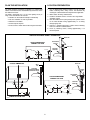
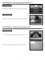
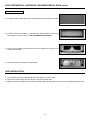
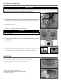
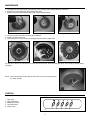
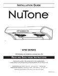
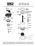
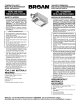
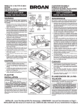
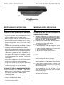
INSTALLATION INSTRUCTIONS
READ AND SAVE THESE INSTRUCTIONS
HB0043
NUTONE RANGE HOOD
NTM SERIES
IMPORTANT SAFETY INSTRUCTIONS
!
IMPORTANT SAFETY INSTRUCTIONS
WARNING
!
TO REDUCE THE RISK OF INJURY TO PERSON(S) IN
THE EVENT OF A RANGE TOP GREASE FIRE,
OBSERVE THE FOLLOWING*:
TO REDUCE THE RISK OF FIRE, ELECTRIC SHOCK, OR
INJURY TO PERSON(S) OBSERVE THE FOLLOWING:
1. Use this unit only in the manner intended by the manufacturer.
If you have questions, contact the manufacturer at the
address or telephone number listed in the warranty.
2. Before servicing or cleaning unit, switch power off at service
panel and lock service disconnecting means to prevent
power from being switch on accidentally. When the service
disconnecting means cannot be locked, securely fasten a
prominent warning device, such as a tag, to the service
panel.
3. Installation work and electrical wiring must be done by qualified
personnel in accordance with all applicable codes and standards,
including fire-rated construction codes and standards.
4. Sufficient air is needed for proper combustion and exhausting
of gases through the flue (chimney) of fuel burning equipment
to prevent backdrafting. Follow the heating equipment
manufacturer’s guidelines and safety standards such as
those published by the National Fire Protection Association
(NFPA), and the American Society for Heating, Refrigeration
and Air Conditioning Engineers (ASHRAE), and the local
code authorities.
5. When cutting or drilling into wall or ceiling, do not damage
electrical wiring and other hidden utilities.
6. Ducted fans must always be vented to the outdoors.
7. Do not use this unit with any other solid-state speed control
device.
8. To reduce the risk of fire, use only steel ductwork.
9. This unit must be gounded.
1. SMOTHER FLAMES with a close-fitting lid, cookie sheet, or
metal tray, then turn off the burner. BE CAREFUL TO PREVENT
BURNS. IF THE FLAMES DO NOT GO OUT IMMEDIATELY,
EVACUATE AND CALL THE FIRE DEPARTMENT.
2. NEVER PICK UP A FLAMING PAN – You may be burned.
3. DO NOT USE WATER, including wet dishcloths or towels –
This could cause a violent steam explosion.
4. Use an extinguisher ONLY if:
A. You know you have a Class ABC extinguisher and you
know how to operate it.
B. The fire is small and contained in the area where it started.
C. The fire department has been called.
D. You can fight the fire with your back to an exit.
* Based on “Kitchen Fire Safety Tips” published by NFPA.
CAUTION
1. For general ventilating use only. Do not use to exhaust
hazardous or explosive materials and vapors.
2. To avoid motor bearing damage and noisy and/or
unbalanced impellers, keep drywall spray, construction dust,
etc. off power unit.
3. For best capture of cooking impurities, the bottom of the
hood should be a minimum of 25.6” (27.6” over a gas range)
above the cooking surface.
4. To reduce the risk of fire and to properly exhaust air on a
ducted installation, be sure to duct air outside – Do not
exhaust air into spaces within walls or ceiling or into attics,
crawl spaces, or garage.
5. Please read specification label on product for further
information and requirements.
TO REDUCE THE RISK OF A RANGE TOP GREASE FIRE:
a) Never leave surface units unattended at high settings.
Boilovers cause smoking and greasy spillovers that may
ignite. Heat oils slowly on low or medium settings.
b) Always turn hood ON when cooking at high heat or when
cooking flaming foods.
c) Clean ventilating fans frequently. Grease should not be
allowed to accumulate on fan or filter.
d) Use proper pan size. Always use cookware appropriate for
the size of the surface element.
WARNING
-1-
PLAN THE INSTALLATION
LOCATION PREPARATION
The hood should be mounted to the bottom of a standard wall
cabinet. If the hood must be mounted directly to the wall, secure
the hood to wall studs.
The hood is connected to a 110-120 V AC lighting circuit (15
amp) in the circuit breaker or fuse box.
• Ductwork can be installed vertically or horizontally.
• Duct runs should be as short as possible.
• Avoid the use of elbows.
• Use duct tape at all joints.
• Do not use duct smaller than the discharge on the hood.
1. Use the dimensional drawings below to lay out the range
hood’s mounting holes, wiring access and ductwork by
marking the cabinet bottom and drywall where applicable.
2. Make cutouts for wiring and ductwork.
3. Install the ductwork so that it is flush to the range hood’s
mounting surface.
4. Run two-conductor wire (with ground) from a power source
to the hood location. Bring approximately 12” of wiring
through wiring hole.
5. Drill four 3⁄32” diameter pilot holes at points where mounting
holes are marked in cabinet bottom.
6. Insert (4) mounting screws, leaving approximately 1⁄4” of
thread exposed.
VERTICAL DISCHARGE USING 6” ROUND DUCT
ROOF CAP
ADJUSTABLE
ELBOW
CUTOUT DIMENSIONS
CABINET TOP VIEW
WALL CAP
1” TYP.
6” DIA.
SUPPLIED
ADAPTER
1” TYP.
C
L
9½” TYP.
5½”
12”
2”
1” TYP.
HORIZONTAL DISCHARGE USING 3 1⁄4” X 10” DUCT
CUTOUT DIMENSIONS
VERTICAL DISCHARGE USING 3 1⁄4” X 10” DUCT
ROOF CAP
WALL
CAP
SUPPLIED
ADAPTER/DAMPER
(INSIDE THE HOOD)
EAVES
CAP
ADJUSTABLE
ELBOW
CUTOUT DIMENSIONS
CABINET TOP VIEW
SUPPLIED
ADAPTER
3¼”
¾”
C
L
1” TYP.
1” TYP.
10¼”
10¼”
9½” TYP.
3¼”
C
L
12”
12”
2”
2”
CABINET BOTTOM VIEW
HH0055
-2-
2¼”
1” TYP.
WALL
CAP
HOOD PREPARATION
1. Remove the bottom panel of the hood by removing its (5) mounting screws and set
aside.
MOUNTING SCREW LOCATIONS
HO0046
2. Unplug the small white connector inside the hood.
HE0054
3. Remove the (2) screws retaining the electrical box cover and set aside. Punch out the
wiring knock-out located on the TOP of the unit and install an approved wire clamp (not
included).
SCREW LOCATIONS
HO0047
HOOD PREPARATION - VERTICAL DISCHARGE INSTALLATION
1. Install the small shutoff plate (with its gasket) INSIDE the back of the hood, using
10 screws (included).
HO0048
2. Install the large shutoff plate on the BACK of the hood, using 5 screws (included).
HO0049
3. Install the rubber gasket (included) on the top of the hood, as shown beside.
HO0050
-3-
HOOD PREPARATION - VERTICAL DISCHARGE INSTALLATION (CONT’D)
6” ROUND
DUCT INSTALLATION
4. Mount the 6” round adapter on the top of the hood, using 10 screws (included).
HJ0001
3 ⁄4” X 10” DUCT
1
INSTALLATION
4. Mount the 31⁄4” x 10” adapter on the top of the hood, using 10 screws (included).
HJ0003
HOOD PREPARATION - HORIZONTAL DISCHARGE INSTALLATION
31⁄4” X 10” DUCT
INSTALLATION
1. Install the rubber gasket (included) on the top of the hood, as shown beside.
HO0050
2. Mount the shutoff plate on the top of the hood, using 10 screws (included).
HO0051
-4-
HOOD PREPARATION - HORIZONTAL DISCHARGE INSTALLATION (CONT’D)
31⁄4” X 10” DUCT
INSTALLATION
3. If installed, remove and discard the large shutoff plate located on the BACK of the hood.
HO0049
4. If installed, remove and discard the small shutoff plate located INSIDE the back of the
hood. Keep the screws for further use. DO NOT RENMOVE THE GASKET!
HO0048
5. Using 10 screws previously removed in point 4, install the adapter on the gasket, in the
inside back of the hood.
HJ0005
6. Install the damper in the adapter, as shown beside.
HJ0002
HOOD INSTALLATION
1. Insert the power cable in the hood and tighten the wire clamp to secure the cable.
2. Align hood’s keyhole mouting slots over the four (4) partially installed screws.
3. Making sure the duct positions over the hood’s duct adapter, push the hood against the rear wall. Secure hood by tightening screws.
-5-
ELECTRICAL CONNECTION
! WARNING
Risk of electrical shock. Electrical wiring must be done by qualified personnel in accordance with all applicable
codes and standards. Before connecting wires, switch power off at service panel and lock service disconnecting
means to prevent power from being switched on accidentally.
A
1. Using provided wire connectors, connect wires as follow: BLACK wire to BLACK wire (A),
WHITE wire to WHITE wire (B) and GREEN or BARE wire with GREEN-YELLOW wire (C).
B
C
2. Reinstall wiring box cover.
HE0055
3. Plug back the small white connector inside the hood.
CAUTION
Do not forget to plug the white connector when reinstalling the bottom
panel to the hood.
4. Reinstall bottom panel. Make sure both grease guides are aligned with the holes. Install
the grease pan.
HD0141
A
B
5. Using long nose pliers, pull out the end of each grease guides (A). Then, set them in
such a way their flange slightly protrudes above the bottom panel surface (B).
HD0149
LIGHT BULB
RETAINING SCREW
This hood uses (1) appliance bulb 120 V 40 W maximum (not included).
To access the bulb, unscrew the light diffuser retaining screw.
HO0054
To remove, rotate the bulb counterclockwise.
Install the bulb by rotating clockwise in its socket holder.
Reinstall the light diffuser.
HO0053
-6-
MAINTENANCE
1. Disengage the small grease guard cups from the grease guard by turning counterclockwise and remove.
2. Remove the screw retaining the grease guard to the hood.
3. Remove the grease guard from the hood. Then remove the bottom panel.
1
HD0142
2
3
HD0144
HD0143
4. Unscrew the clips and remove the wheel grease collector.
5. Remove the wheel center cap.
6. Loosen the wheel set screw in order to disengage the wheel from its motor shaft.
4
HD0145
6
5
HD0146
HD0147
Let soak for 30 minutes all removed parts in warm water with soft soap. Then wash with nylon brush, rinse and dry completely before
reinstalling.
NOTE: When reinstalling the wheel, align the end of the set screw with the flat part of
the motor shaft (A).
A
HD0148
CONTROL
1.
2.
3.
4.
5.
Light switch.
High speed switch.
Middle speed switch.
Low speed switch.
Power switch.
HC0018
-7-
lamp
high
middle
low
on/off
1
2
3
4
5
WIRING DIAGRAM
N
YELLOW-GREEN
BLACK
WHITE
L
POWER PANEL
LEFT
RIGHT
RED
BLUE
M
YELLOW
WHITE
YELLOW
WHITE
STOP
CAPACITOR
LOW
MIDDLE
HIGH
LAMP
CAPACITOR
GRAY
BROWN
YELLOW
BROWN
BLUE
BROWN
GRAY
BLUE
BLACK
BROWN
GRAY
BLUE
BLACK
M
LAMP
HE0056
SERVICE PARTS
1
KEY #
1
2
3
4
5
6
7
8
9
10
PART #
30280018
30080420
30080418
30111040
30111050
30111049
30111042
30111041
30390543
30111043
DESCRIPTION
SWITCH BOARD
LEFT MOTOR (CCW)
RIGHT MOTOR (CW)
BLOWER WHEEL
WHEEL CENTER CAP
WHEEL GREASE COLLECTOR
GREASE PAN
LIGHT DIFFUSER
METAL GUARD
GREASE GUARD CUP
QTY
1
1
1
2
2
2
1
1
2
2
3
2
4
5
6
7
8
9
10
HL0059
-8-
BROAN-NUTONE
CANADA INC.
One Year Limited Warranty
Broan-NuTone Canada warrants to the original purchaser of its products that such products will be free from defects in
materials and workmanship for a period of one (1) year from the date of original purchase. THERE ARE NO OTHER
WARRANTIES, EXPRESSED OR IMPLIED, INCLUDING, BUT NOT LIMITED TO, IMPLIED WARRANTIES OF
MERCHANTABILITY OR FITNESS FOR A PARTICULAR PURPOSE.
During this one year period, Broan-NuTone Canada will, at its option, repair, replace, without charge, any product or
part which is found to be defective under normal use and service.
THIS WARRANTY DOES NOT EXTEND TO FLUORESCENT LAMP STARTERS OR TUBES, BULBS OR BATTERIES,
FILTERS, DUCT, ROOF CAPS, WALL CAPS AND OTHER ACCESSORIES FOR DUCTING. This warranty does not
cover (a) normal maintenance and service or (b) any products or parts which have been subject to misuse, negligence,
accident, improper maintenance or repair (other than by Broan-NuTone Canada or an authorized representative), faulty
installation or installation contrary to recommended installation instructions.
The duration of any implied warranty is limited to the one year period as specified for the express warranty.
BROAN-NUTONE CANADA’S OBLIGATION TO REPAIR OR REPLACE, AT BROAN-NUTONE CANADA’S OPTION,
SHALL BE THE PURCHASER’S SOLE AND EXCLUSIVE REMEDY UNDER THIS WARRANTY. BROAN-NUTONE
CANADA SHALL NOT BE LIABLE FOR INCIDENTAL, CONSEQUENTIAL OR SPECIAL DAMAGES ARISING OUT FOR
OR IN CONNECTION WITH PRODUCT USE OR PERFORMANCE. This warranty supercedes all prior warranties.
To qualify for warranty service, you must (a) notify Broan-NuTone Canada at the address stated below or telephone
1-888-882-7626, (b) give the model number and part identification and (c) describe the nature of any defect in the product
or part. At the time of requesting warranty service, you must present evidence of the original purchase date.
Date of Installation
Builder or Installer
Model No. and Product Description
IF YOU NEED ASSISTANCE OR SERVICE:
For the location of your nearest Broan-NuTone Canada Incorporated dealer
Dial Free 1-888-882-7626
Please be prepared to provide:
Product model number • Date and proof of purchase • The nature of the difficulty
Broan-NuTone Canada Incorporated
1140 Tristar Drive, Mississauga, Ontario, Canada L5T 1H9
Product specifications subject to change without notice.
-9-