1
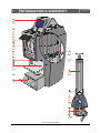
FAST & FLUID MANAGEMENT
HA200-400-600
ENGLISH
FAST & FLUID MANAGEMENT
HA200 / HA400 / HA600 - V1.71 – 21-07-2004
FAST & FLUID MANAGEMENT
HA200 / HA400 / HA600 - V1.71 – 21-07-2004
EU DECLARATION OF CONFORMITY
Fast & Fluid Management, the Netherlands
A Unit of IDEX Corporation
Hub van Doorneweg 31
2171 KZ Sassenheim, the Netherlands
declare that:
Automatic dispensers
model:
Harbil
types:
HA200, HA400 & HA600
are in compliance with the following directives:
Machinery Directive 98/37/EC
Low Voltage Directive 73/23/EEC
Electromagnetic Compatibility Directive 89/336/EEC
according to the following harmonized standards:
EN 292-1, EN 292-2, EN 418 & EN 1050
EN 60204-1
EN 61000-6-2, EN 61000-6-3, EN 61000-3-2 & EN 61000-3-3
Sassenheim, 04-08-2003
ir. K. Meeusen
Vice President Manufacturing
Fast & Fluid Management, the Netherlands
A Unit of IDEX Corporation
EU-KONFORMITÄTSERKLÄRUNG
Wir,
Fast & Fluid Management, Nierderlände
A Unit of IDEX Corporation
Hub van Doorneweg 31
2171 KZ Sassenheim, Niederlände
erklären dass:
Automatic dispensers
model:
Harbil
types:
HA200, HA400 & HA600
konform sind mit den einschlägigen Bestimmungen der EG-Maschinenrichtlinie:
Maschinenrichtlinie 98/37/EG
Niederspannungsrichtlinie 73/23/EWG
EMV-Richtlinie EMC 89/336/EWG
folgende harmonisierten Normen zur Anwendung gelangten:
EN 292-1, EN 292-2, EN 418 & EN 1050
EN 60204-1
EN 61000-6-2, EN 61000-6-3, EN 61000-3-2 & EN 61000-3-3
Sassenheim, 04-08-2003
ir. K. Meeusen
Vice President Manufacturing
Fast & Fluid Management, Niederlände
A Unit of IDEX Corporation
FAST & FLUID MANAGEMENT
HA200 / HA400 / HA600 - V1.71 – 21-07-2004
EG CONFORMITEITSVERKLARING
Wij,
Fast & Fluid Management, Nederland
A Unit of IDEX Corporation
Hub van Doorneweg 31
2171 KZ Sassenheim, Nederland
verklaren dat:
Automatic dispensers
model:
Harbil
types:
HA200, HA400 & HA600
in overeenstemming met de volgende richtlijnen:
Machinerichtlijn 98/37/EC
Laagspanningsrichtlijn 73/23/EEC
Richtlijn EMC 89/336/EEC
voldoen aan de volgende geharmoniseerde Europese normen:
EN 292-1, EN 292-2, EN 418 & EN 1050
EN 60204-1
EN 61000-6-2, EN 61000-6-3, EN 61000-3-2 & EN 61000-3-3
Sassenheim, 04-08-2003
ir. K. Meeusen
Vice President Manufacturing
Fast & Fluid Management, Nederland
A Unit of IDEX Corporation
DÉCLARATION CE DE CONFORMITÉ
Nous,
Fast & Fluid Management, Pays-Bas
A Unit of IDEX Corporation
Hub van Doorneweg 31
2171 KZ Sassenheim, Pays-Bas
déclarons que:
Automatic dispensers
model:
Harbil
types:
HA200, HA400 & HA600
sont en conformité avec la Directive pour les machines:
Directive machines 98/37/CEE
Directive basse tension 73/23/CEE
Compatibilité électromagnétique 89/336/CEE
sont en conformité avec les normes Européènnes harmonisés:
EN 292-1, EN 292-2, EN 418 & EN 1050
EN 60204-1
EN 61000-6-2, EN 61000-6-3, EN 61000-3-2 & EN 61000-3-3
Sassenheim, 04-08-2003
ir. K. Meeusen
Vice President Manufacturing
Fast & Fluid Management, Pays-Bas
A Unit of IDEX Corporation
FAST & FLUID MANAGEMENT
HA200 / HA400 / HA600 - V1.71 – 21-07-2004
DECLARACIÓN CE DE CONFORMIDAD
Fast & Fluid Management, the Netherlands
A Unit of IDEX Corporation
Hub van Doorneweg 31
2171 KZ Sassenheim, the Netherlands
declara que:
Automatic dispensers
model:
Harbil
types:
HA200, HA400 & HA600
están en conformidad con la directiva para las máquinas:
La directiva para las máquinas 98/37/CEE
La directiva de baja tensión 73/23/CEE
Compatibilidad electromagnética 89/336/CEE
están en conformidad con las Normas Europeas armonizadas:
EN 292-1, EN 292-2, EN 418 & EN 1050
EN 60204-1
EN 61000-6-2, EN 61000-6-3, EN 61000-3-2 & EN 61000-3-3
Sassenheim, 04-08-2003
ir. K. Meeusen
Vice President Manufacturing
Fast & Fluid Management, the Netherlands
A Unit of IDEX Corporation
DICHIARAZIONE CE DI CONFORMITÀ
Fast & Fluid Management, the Netherlands
A Unit of IDEX Corporation
Hub van Doorneweg 31
2171 KZ Sassenheim, the Netherlands
dichiariamo que:
Automatic dispensers
model:
Harbil
types:
HA200, HA400 & HA600
sono in conformità alla Direttiva-CE Macchine:
Direttiva macchine 98/37/CEE
Bassa tensione 73/23/CEE
Compatibilita elettromagnetica 89/336/CEE
sono in conformittà con Norme Europee di normalzzazione:
EN 292-1, EN 292-2, EN 418 & EN 1050
EN 60204-1
EN 61000-6-2, EN 61000-6-3, EN 61000-3-2 & EN 61000-3-3
Sassenheim, 04-08-2003
ir. K. Meeusen
Vice President Manufacturing
Fast & Fluid Management, the Netherlands
A Unit of IDEX Corporation
FAST & FLUID MANAGEMENT
HA200 / HA400 / HA600 - V1.71 – 21-07-2004
DECLARAÇÃO CE CONFORMIDADE
Fast & Fluid Management, the Netherlands
A Unit of IDEX Corporation
Hub van Doorneweg 31
2171 KZ Sassenheim, the Netherlands
declara que:
Automatic dispensers
model:
Harbil
types:
HA200, HA400 & HA600
está em conformidade com a Directiva Mãquinas:
Directiva para as mãquinas 98/37/CE
Directiva baixa tensão 73/23/CE
Directiva EMC 89/336/CE
está em conformidade com as Normas Europeias:
EN 292-1, EN 292-2, EN 418 & EN 1050
EN 60204-1
EN 61000-6-2, EN 61000-6-3, EN 61000-3-2 & EN 61000-3-3
Sassenheim, 04-08-2003
ir. K. Meeusen
Vice President Manufacturing
Fast & Fluid Management, the Netherlands
A Unit of IDEX Corporation
EF-OVERENSSTEMMELSESEKLÆRINGEN
Fast & Fluid Management, the Netherlands
A Unit of IDEX Corporation
Hub van Doorneweg 31
2171 KZ Sassenheim, the Netherlands
Automatic dispensers
model:
Harbil
types:
HA200, HA400 & HA600
til hvilken denne erklæring er anvendt i overensstemmelse med EU’s Maskindirektiv:
98/37/EØF
73/23/EØF
EMC 89/336/EØF
er i overensstemmelse med harmoniserede Europæiske Standarder :
EN 292-1, EN 292-2, EN 418 & EN 1050
EN 60204-1
EN 61000-6-2, EN 61000-6-3, EN 61000-3-2 & EN 61000-3-3
Sassenheim, 04-08-2003
ir. K. Meeusen
Vice President Manufacturing
Fast & Fluid Management, the Netherlands
A Unit of IDEX Corporation
FAST & FLUID MANAGEMENT
HA200 / HA400 / HA600 - V1.71 – 21-07-2004
EU DEKLARASJON AV OVERENSTEMMELSE
Fast & Fluid Management, the Netherlands
A Unit of IDEX Corporation
Hub van Doorneweg 31
2171 KZ Sassenheim, the Netherlands
herved erklaeres at:
Automatic dispensers
model:
Harbil
types:
HA200, HA400 & HA600
er in overenstemmelse med EU-Direktivet for maskiner:
98/37/EEC
73/23/EEC
EMC89/336/EEC
er in overenstemmelse med harmoniserte Europeiske Standarder:
EN 292-1, EN 292-2, EN 418 & EN 1050
EN 60204-1
EN 61000-6-2, EN 61000-6-3, EN 61000-3-2 & EN 61000-3-3
Sassenheim, 04-08-2003
ir. K. Meeusen
Vice President Manufacturing
Fast & Fluid Management, the Netherlands
A Unit of IDEX Corporation
EG-FÖRSÄKRAN OM ÖVERENSSTÄMMELSE
Fast & Fluid Management, the Netherlands
A Unit of IDEX Corporation
Hub van Doorneweg 31
2171 KZ Sassenheim, the Netherlands
försäkrar härmed att :
Automatic dispensers
model:
Harbil
types:
HA200, HA400 & HA600
är tillverkade i överenstämmelse med EG Maskindirektiv:
98/37/EEC
73/23/EEC
EMC 89/336/EEC
är tillverkade i överenstämmelse med Följande harmoniserande Standarder:
EN 292-1, EN 292-2, EN 418 & EN 1050
EN 60204-1
EN 61000-6-2, EN 61000-6-3, EN 61000-3-2 & EN 61000-3-3
Sassenheim, 04-08-2003
ir. K. Meeusen
Vice President Manufacturing
Fast & Fluid Management, the Netherlands
A Unit of IDEX Corporation
FAST & FLUID MANAGEMENT
HA200 / HA400 / HA600 - V1.71 – 21-07-2004
EY-VAATIMUSTENMAKAISUUSVAKTUUTUS
Fast & Fluid Management, the Netherlands
A Unit of IDEX Corporation
Hub van Doorneweg 31
2171 KZ Sassenheim, the Netherlands
vakutta että:
Automatic dispensers
model:
Harbil
types:
HA200, HA400 & HA600
täyttää konedirektiivin:
98/37/ETY
73/23/ETY
EMC 89/336/ETY
ja siihen liittyvien muutosten sekä ne voimaansaattavien kansallisten säädöstn määräykset
seuraavia yhdenmukaistettuja standardeja on sovellettu:
EN 292-1, EN 292-2, EN 418 & EN 1050
EN 60204-1
EN 61000-6-2, EN 61000-6-3, EN 61000-3-2 & EN 61000-3-3
Sassenheim, 04-08-2003
ir. K. Meeusen
Vice President Manufacturing
Fast & Fluid Management, the Netherlands
A Unit of IDEX Corporation
EBE SAMRÆMISYFIRLYSING
Fast & Fluid Management, the Netherlands
A Unit of IDEX Corporation
Hub van Doorneweg 31
2171 KZ Sassenheim, the Netherlands
Hér meδ er pvi lyst yfir aδ:
Automatic dispensers
model:
Harbil
types:
HA200, HA400 & HA600
Er i samræmi viδ ákvæδi tilskipunnar um vélar:
98/37/EEC
73/23/EEC
EMC 89/336/EEC
Eftirtaldir samræmisstaδlar hafa veriδ notaδir:
EN 292-1, EN 292-2, EN 418 & EN 1050
EN 60204-1
EN 61000-6-2, EN 61000-6-3, EN 61000-3-2 & EN 61000-3-3
Sassenheim, 04-08-2003
ir. K. Meeusen
Vice President Manufacturing
Fast & Fluid Management, the Netherlands
A Unit of IDEX Corporation
FAST & FLUID MANAGEMENT
HA200 / HA400 / HA600 - V1.71 – 21-07-2004
DEKLARACJA ZGODNOŚCI ZE STANDARTAMI UE
Fast & Fluid Management, the Netherlands
A Unit of IDEX Corporation
Hub van Doorneweg 31
2171 KZ Sassenheim, the Netherlands
deklaruje, że:
Automatyczne dozowniki:
model:
Harbil
typy:
HA200, HA400 & HA600
Spełniają wymogi poniższych dyrektyw:
Dyrektywa dotycząca maszyn 98/37/EC
Dyrektywa dotycząca niskich napięć 73/23/EEC
Dyrektywa zgodności elektromagnetycznej 89/336/EEC
zgodnie z następującymi normami zharmonizowanymi:
EN 292-1, EN 292-2, EN 418 & EN 1050
EN 60204-1
EN 61000-6-2, EN 61000-6-3, EN 61000-3-2 & EN 61000-3-3
Sassenheim, 04-08-2003
ir. K. Meeusen
Vice President Manufacturing
Fast & Fluid Management, the Netherlands
A Unit of IDEX Corporation
FAST & FLUID MANAGEMENT
HA200 / HA400 / HA600 - V1.71 – 21-07-2004
FAST & FLUID MANAGEMENT
HA200 / HA400 / HA600 - V1.71 – 21-07-2004
I
INTRODUCTION & WARRANTY
page 13
Introduction
Warranty conditions
Explanation of drawings
II
SAFETY INSTRUCTIONS
page 17
III
INSTALLATION
page 19
Installing the dispenser
Installing the computer and software
IV
OPERATION
page 23
First time operation
Dispensing
V
MAINTENANCE
page 27
Daily maintenance
Weekly maintenance
Monthly maintenance
Flat screen maintenance
VI
TROUBLESHOOTING
page 29
Introduction
Problem solving
Service
Fuses
VII
TECHNICAL SPECIFICATIONS
Electrical wiring diagram
FAST & FLUID MANAGEMENT
HA200 / HA400 / HA600 - V1.71 – 21-07-2004
page 31
FAST & FLUID MANAGEMENT
HA200 / HA400 / HA600 - V1.71 – 21-07-2004
I
INTRODUCTION & WARRANTY
A-
Introduction
page 13
By selecting a Fast & Fluid Management Color Dispenser you have opted for a product which is the
result of intensive research. Top-quality components, craftsmanship and a modern ergonomic design all
serve to guarantee a long service life and a high degree of user friendliness.
The machine complies with Council Directives 89/392/EEC on machines, 89/336/EEC on
electromagnetic compatibility, and 73/32/EEC on electrical equipment intended for use within given
voltage limits, as enacted by the Council of Ministers of the European Community. The machine is
furnished with a CE mark.
B-
Warranty conditions
In these warranty conditions, 'F&FM' is understood to mean Fast & Fluid Management. The warranty conditions
incorporated into F&FM's general conditions of sale are summarized as follows (for free general conditions you can
contact F&FM):
1.
2.
3.
4.
5.
6.
7.
F&FM guarantees the proper operation of any goods which it supplies, for a period of one year, except
where a breakdown is the result of normal wear and tear. The cost of any inspection activities carried
out by F&FM, with the aim of establishing whether or not a breakdown is covered by the warranty will be
reimbursed by the other party if it transpires that the breakdown is not covered by the warranty. If it
transpires that a breakdown is covered by the warranty then F&FM will supply identic al or equivalent
goods under the conditions referred to in point 6 of the general conditions of sale. The warranty
obligation described in this article only applies if the goods supplied by F&FM have been used in
accordance with the manual. Time spent on warranty-related activities, including travel time, travel costs
and accommodation costs, are charged at current rates.
In contrast to the above, F&FM will not be held to any warranty obligation if:
a)
Repairs have been carried out, or attempted, by the other party or a third party, unless F&FM had
previously declined to repair the goods for a fair price;
b)
F&FM demonstrates that the defect did not emerge during testing;
c)
The other party fails to inform F&FM of the defect immediately, if possible either by letter and/or by
fax, providing full, accurate details and/or has failed to comply fully with F&FM's instructions;
d)
The other party has failed to use or treat the goods properly or in accordance with F&FM's
instructions;
e)
The damage has been caused by incidents, beyond F&FM's supervision, which have occurred either
during transport or installation.
In the following text, the expression "Software" will be understood to mean the standard computer
software supplied by F&FM to the other party, recorded on a computer-readable storage medium, plus
the accompanying documentation (Software Manual) and including any improved and/or new versions
supplied. The expression "processing unit" (PU) is understood to mean the machine for which and with
which the Software is supplied, and which is the sole machine on which the Software may be used.
The other party is authorized to copy the Software either in its entirety, or in part, (up to a maximum of
2 copies) for purposes of internal security. These copies will be furnished with the same marks,
designations relating to copyright and other registration numbers as the original version of the Software.
The other party will neither amend, translate, decompile nor adapt the Software, nor convert it into
source code, without express written permission from F&FM. If the other party so requests, F&FM will
provide that party with the information required to render the Software interoperable with other
software.
In the event that the PU experiences a breakdown, the other party may use the softw are on another
processing unit until the PU is again operational. The other party will inform F&FM of this within 5 days.
If it is a requirement that the Software be definitively transferred from the PU to another processing unit
then the other party shall request permission from F&FM, which will not withhold such permission on
unreasonable grounds.
FAST & FLUID MANAGEMENT
HA200 / HA400 / HA600 - V1.71 – 21-07-2004
I
INTRODUCTION & WARRANTY
FAST & FLUID MANAGEMENT
HA200 / HA400 / HA600 - V1.71 – 21-07-2004
page 14
I
INTRODUCTION & WARRANTY
C-
Explanation of drawings
Dispenser
1.
2.
3.
4.
5.
6.
7.
8.
9.
10.
11.
12.
13.
14.
15.
16.
17.
18.
19.
20.
TFT color display
Folding top lid
Top lid push bar
Side panel
Canister lid
Keyboard & touch pad, can table switch
Canister
Pump gripper spindle
Electronics power board
Pump assembly (details below)
Spindle stepper motor
Emergency stop
Valve gripper actuator
Brush tray access door
Optional access door
Lower Service panel & computer access
Can table
Can table actuator
Step (for easy canister access)
Canister turntable
Pump assembly
21.
22.
23.
24.
25.
26.
27.
28.
29.
30.
31.
32.
Disc grip
Pump cap
Piston rod
Pump tube
Piston
Valve body
Pin sensor
Canister mount
Ball valve housing
Ball valve
Ball valve arm
Insert
FAST & FLUID MANAGEMENT
HA200 / HA400 / HA600 - V1.71 – 21-07-2004
page 15
FAST & FLUID MANAGEMENT
HA200 / HA400 / HA600 - V1.71 – 21-07-2004
II
SAFETY INSTRUCTIONS
A-
General safety instructions
page 17
Attention! Before installing the equipment and setting it in operation,
please read the instructions for use carefully. This is safer for yourself
and prevents unnecessary damage to the machine.
The manufacturer accepts no liability if the instructions below are not followed:
1.
2.
3.
4.
5.
6.
7.
8.
B-
If a machine has been damaged (during transport, for example), do not attempt to set it in
operation. When in doubt, first contact either your supplier or the F&FM service department.
The equipment should be positioned and connected up in strict accordance with the
installation instructions.
All local safety regulations and ordinances should be observed.
The machine may be connected only to a 230V/16A/50Hz or 100-110V/25A/50-60HZ
earthed wall socket installed in accordance with the regulations.
Users should see to it that the machine is kept in good condition. Defective components
should be replaced.
In order to prevent physical injury, the doors should be closed and the paneling fitted during
normal use.
All service activities (other than routine maintenance and adjustments) may only be carried out
by qualified technicians. See to it that the mains lead is always kept unplugged while repairs
are being carried out.
Because of the design of the valve, a nozzle drill may never be used. Cleaning is done by
running the cleaning program.
Specific warnings in this manual
Attention! Switching off the dispenser with the emergency stop will also
stop colorant agitation.
Attention! The punch knife is very sharp! Do not hold can while punching.
Attention! MOVING PARTS CAN CAUSE INJURY. Always turn off power
(e.g. by pressing emergency stop) before accessing moving parts.
FAST & FLUID MANAGEMENT
HA200 / HA400 / HA600 - V1.71 – 21-07-2004
FAST & FLUID MANAGEMENT
HA200 / HA400 / HA600 - V1.71 – 21-07-2004
III
INSTALLATION
page 19
Operation
A-
Installing the dispenser
Step 1
Unpack the machine
>
Place the skid near the place
of installation.
>
Remove the cardboard box.
Remove the plastic foil
around the machine.
Be careful not to damage the body and surfaces of your Harbil with
any tools while unpacking it.
Step 2
Remove loose components
>
Unlock the service and back
panel by pushing the two
black handles down
simultaneously.
>
Remove the panel by pulling
it towards you and
subsequently lifting it.
FAST & FLUID MANAGEMENT
HA200 / HA400 / HA600 - V1.71 – 21-07-2004
Remove all packages and
loose components from
within the machine.
III
INSTALLATION
page 20
Operation
Step 3
Detach the dispenser from its transport skid
>
Carefully maneuver the
machine off the skid onto
its rear wheels and roll it to
its final operational position.
Unscrew labeled bolt in
back of machine, in the
computer cavity.
Unscrew the labeled bolt in
the front of machine, under
the can table.
Step 4
>
Mount external hardware bracket (optional)
>
The bracket can be mounted
on either side of the
dispenser.
>
Mount bracket with
supplied M6 bolt at desired
angle.
FAST & FLUID MANAGEMENT
HA200 / HA400 / HA600 - V1.71 – 21-07-2004
Guide cables through slot in
bottom service panel and
connect to computer inside.
III
INSTALLATION
page 21
Operation
Step 5
Mount manual punch (optional)
>
>
Adjust M4 screws to
center punch position under
nozzle. Place new (slotted)
bottom service panel.
Mount manual punch with
four supplied bolts.
Remove bottom service
panel. Four mounting nuts
are now visible.
Please ensure punching position of the manual punch is directly under
dispensing nozzle. Adjust M4 screws if necessary.
Step 6
Mount electric punch (optional)
>
Three nuts for mounting the
electric punch are located
around the dispense nozzle.
>
Mount electric punch with
three supplied M6 bolts.
Take care in positioning the
trigger bolt.
Carefully replace can
detection plate and ensure
trigger bolt is correctly
positioned.
Please ensure the trigger bolt on the electric punch correctly triggers
the can detection plate.
FAST & FLUID MANAGEMENT
HA200 / HA400 / HA600 - V1.71 – 21-07-2004
III
INSTALLATION
page 22
Operation
B-
Installing the computer and software
Step 1
Place and connect computer to dispenser
>
Place computer in cavity
and fixate with supplied
fastener.
Remove the back panel
adjust tray height to suit
computer model (for optimal
accessibility of CD-ROM).
Step 2
>
Install dispenser software on computer
>
Install all necessary software
provided by software
supplier. Check software
manual for details.
Use software to test basic
functions of dispenser
before filling.
Check software manual for
testing procedure.
FAST & FLUID MANAGEMENT
HA200 / HA400 / HA600 - V1.71 – 21-07-2004
Connect dispenser
connector to COM1
(default) and mouse,
keyboard and other
appliances to designated
computer ports.
IV
OPERATION
page 23
Operation
A-
First time operation
Step 1
Switching ON the dispenser & computer
>
Step 2
Unlock the emergency stop button on the front of the machine by
turning clockwise. The machine is automatically switched on
when the power connector at the back of the dispenser is
plugged into a 220V or 100V-110V wall socket.
Please be aware that the Harbil series dispensers are fitted with
sleeping timers as standard. This means that after approximately
30 minutes the dispenser will enter a power saving modus in
which all secondary units (e.g. sensors) are switched off
automatically. Stirring is not affected by this modus.
To awake the dispenser from its sleeping modus, perform any
command from the dispensing software or press either of the
can table buttons.
Switching OFF the dispenser & computer
>
Please note that with normal operation there should be no
reason to take the power off the dispenser. In case the
dispenser must be switched off, there are several ways of
achieving this:
1) Shut down the computer and unplug the power connector at
the back of the machine.
2) Shut down the computer and switch the internal power
socket behind the bottom service panel at the front of the
machine.
3) Shut down the computer and press the emergency stop
button.
Attention! Switching off the dispenser with the emergency stop will also
stop colorant agitation.
Step 3
Setting the stirring time
The stirring time and interval can be altered from its default
settings*. This can be done through the dispenser software,
check your software manual for instructions.
Please ask your paint supplier for optimal agitation settings for
your specific colorant products.
>
*
Default value is 180 seconds of agitation every 3 hours.
FAST & FLUID MANAGEMENT
HA200 / HA400 / HA600 - V1.71 – 21-07-2004
IV
OPERATION
page 24
Operation
Step 4
Fill the brush tray (nozzle cleaning system)
>
>
Replace the brush tray in
its original position.
Cleaning fluid must be
refreshed daily!
Fill the container with water
or an alternative liquid
proposed by your paint
supplier.
Remove the brush tray by
opening the door and pulling
down the lever supporting it.
Use only cleaning fluids recommended by your paint supplier.
Wrong materials can result in nozzle blockage and reduced accuracy.
Step 5
Fill the canisters with colourant
>
Unfold the step and open the
top lid by sliding it all the way
back.
Remove the canister lids.
>
Check your software
manual for filling sequence.
FAST & FLUID MANAGEMENT
HA200 / HA400 / HA600 - V1.71 – 21-07-2004
Run software purge
program twice to remove
air from system.
IV
OPERATION
page 25
Operation
B-
Dispensing
Step 1
Bring can to correct position
>
The upward movement will
stop automatically.
This is the optimal height
for dispensing.
Move the can table upward
by pressing the can table
switch on the keyboard.
Place the can at the center
of the can table cross hair.
Step 2
>
Punch hole in can lid - ELECTRIC (only if fitted with optional electric punch)
>
>
Attention! The punch knife is very sharp! Do not hold can while punching.
After punching the hole will be exactly under the dispensing nozzle.
Please take care not to move the can before dispensing.
FAST & FLUID MANAGEMENT
HA200 / HA400 / HA600 - V1.71 – 21-07-2004
IV
OPERATION
page 26
Operation
Step 3
Punch hole in can lid - MANUAL (only if fitted with optional manual punch)
>
>
Attention! The punch knife is very sharp! Do not hold can while punching.
Step 4
Dispense colorant into base material
>
Ensure can opening is under
the dispenser nozzle and at
its optimal height (automatic
stop).
>
Choose desired formula as
shown in software manual.
The turntable will
subsequently rotate to
correct positions.
Lower can by pressing can
table button on keyboard
and remove can.
Congratulations!
Dispensing is mainly a software issue. Please read your software
manual thoroughly for all possible options.
FAST & FLUID MANAGEMENT
HA200 / HA400 / HA600 - V1.71 – 21-07-2004
V
MAINTENANCE
page 27
Operation
A-
Daily maintenance
Clean the brush tray, refill canisters and run morning program
Remove the brush tray and
empty the container. Clean
the brush with water and
refill the container with
correct fluid (e.g. water).
Fill canisters if level is low
and update levels in
software. Stir colorant
beforehand.
Start software morning
program to purge valves
and clean nozzles. Check
your software manual for
details.
Use only cleaning fluids recommended by your paint supplier.
Wrong materials can result in nozzle blockage and reduced accuracy.
B-
Weekly maintenance
Remove spilt paint & colorant and refill canisters
Clean can table and outside
parts with diluted detergent.
Check canister content and
refill if necessary.
Always close canister and machine lid after refilling.
Be aware the machine will not agitate if the top lid is not closed!
FAST & FLUID MANAGEMENT
HA200 / HA400 / HA600 - V1.71 – 21-07-2004
V
MAINTENANCE
page 28
Operation
C-
Monthly maintenance
Remove back panel.
Clean dust from computer
cavity and spilt colorant
inside machine.
Check pump valve for
possible malfunctions
(e.g. leakage or blockage).
Attention! MOVING PARTS CAN CAUSE INJURY. Always turn off power
(e.g. by pressing emergency stop) before accessing moving parts.
D-
Flat screen maintenance
Do not use any wetted materials, detergents, solvents, thinners or
other cleaning agents to clean the TFT flat-screen monitor. Its
surface is very delicate!
How to keep your Flatscreen clean:
• Wipe off water droplets or oil immedeately. If you leave the droplets for a long time, staining and
discoloration may occur.
• If the surface of the polarizer is dirty, clean it using some absorbent cotton or soft cloth. The
desirable cleaners are water, IPA (isopropyl alcohol) or Hexane. Do not use ketone type materials
(ex. Acentone), ethyl alcohol, toluene, ethyl acid or methyl chloride. It might permanent damage to
the polarizer due to chemical reaction.
• Gently wipe the screen with a clean camel hair lens brush, or a soft, clean, lint-free cloth. This
removes dust and other particles that can scratch the screen.
• Do not apply pressure to the screen surface when wiping it clean.
• Do not pour or spray any liquid directly onto the screen or case of the LCD monitor. Chemical
cleaners have been reported to damage the screen or case of the LCD monitor.
FAST & FLUID MANAGEMENT
HA200 / HA400 / HA600 - V1.71 – 21-07-2004
VI
TROUBLESHOOTING
A-
Introduction
page 29
Before calling your machine supplier or Service Department, please check whether you can solve the
problem yourself. If you cannot, then call the Service Department for advice. Have the model number
and serial number at hand (these can be found on the silver CE sticker at the behind the service panel at
the front of the machine).
Use the Problem Solving chart below to judge whether you can solve a problem yourself or not. The tool
symbol (() means you cannot solve the problem yourself and the Service Department must be called.
On no occasion remove side panels yourself, this may only be done by trained service personnel. This
chart does not include any of the malfunctions which are reported in an error message by the software.
In the event of a malfunction, these messages and possible solutions are displayed on the monitor.
Attention! MOVING PARTS CAN CAUSE INJURY. Always turn off power
(e.g. by pressing emergency stop) before accessing moving parts.
B-
Problem solving
Symptom
Cause
Action
Valve leaks through the outlet opening
>
>
>
Air bubble in pump
Valve is defective
Worn O-ring(s)
>
>
>
Prime the pump
Replace pump (()
Replace O-ring(s) (
>
>
>
>
>
>
>
Air bubble in the pump
Canister is empty
Piston is defective
Program not correctly booted
Software incorrectly installed
Not connected to power grid
Fuse blown
>
>
>
>
>
>
>
Colours are difficult to reproduce
>
>
>
>
>
Mechanisms are dirty
Quality fluctuations in paste supplied
One or more pastes have thickened
Turntable in wrong position
Leaks around piston(s)
>
>
>
>
Poor monitor picture, or no picture
>
>
>
>
>
>
>
>
>
>
>
>
>
Monitor is switched off
Loose cable(s)
Picture set too dark
Monitor malfunctioning
Loose cable(s)
Windows Regional setting is incorrect
Defective cable(s)
Keyboard is defective
Top lid not closed properly
Timer setting incorrect
Loose cable
Defective cable
Defective motor
>
>
>
>
>
Top lid not closed properly
Piston rod positioned too high
Valve mouth pointing down
Cable(s) loose
Cable or motor defective
Prime the pump
Refill canister
Replace pump (()
Reboot computer & software
Reinstall software
Check power cables
Remove plug from socket, replace
fuse
Clean and oil
Contact paste supplier
Replace paste(s)
Reset (press and unlock emergency
stop button)
Replace piston(s) (()
Switch monitor on
Check cables
Adjust picture correctly
(()
Check cables
Check Windows software manual
(()
(()
Close top lid
Use the software to set the timer
correctly
Check cable
(()
(()
Close top lid
Set piston in lower position
Reposition valve mouth
Check cables
(()
Canister connection leaks around the
suction point
Air is being fed together with the paste
(New) software is not working
No power from power unit
Keyboard is not working
Stirrer is not rotating
Turntable is not turning
>
>
>
>
>
>
>
>
>
>
>
>
>
>
>
>
>
>
>
FAST & FLUID MANAGEMENT
HA200 / HA400 / HA600 - V1.71 – 21-07-2004
VI
TROUBLESHOOTING
C-
Service Department
page 30
If necessary, you can get in touch with your supplier or the local service department, or contact the
manufacturer directly. If you contact the manufacturer, make sure that you have the model number and
serial number to hand. They can be found on the name plate on the machine.
Fast & Fluid Management
P.O. Box 220
2170 AE Sassenheim, the Netherlands
Hub van Doorneweg 31
2171 KZ Sassenheim, the Netherlands
Tel:
+31 (0)252 240 800
Fax:
+31 (0)252 240 882 (service)
+31 (0)252 240 880 (general)
D-
Fuses
Replace fuses behind front panel.
E-
Flat screen – adjust settings
Windows settings & use of buttons at rear of screen
1.
2.
3.
4.
5.
Ensure the (Windows) video
refresh is between 60 and
85 Hz and 800x600 pixels.
Menu UP
Menu DOWN
Power ON/OFF
Value +
Value -
Use button 2 (Menu Down)
to enter the onscreen
menu.
FAST & FLUID MANAGEMENT
HA200 / HA400 / HA600 - V1.71 – 21-07-2004
Run the ‘Autotune’ function
and ‘Position – Center’.
Please save upon exiting.
VII
TECHNICAL SPECIFICATIONS
A-
Electrical wiring diagram
page 31
CABLE 11 (1861994)
CABLE 20 (1862402)
BROWN
-
MGND3
BLUE
HHB14
BROWN
HHB13
BLUE
MGND3
BROWN
HHB12
BLUE
+
-
TRAFO ASSY
M15
AGITATIONMOTOR
+
POWERSUPPLY
CABLE 15 (1861992)
BLUE
BLUE
+
-
M14
+
-
M16
BRUSHMOTOR
BROWN
HHB11
CABLE 14 (1861991)
TRANSFORMER
BROWN
BLUE
HHB10
BROWN
HHB9
BROWN
BLUE
HHB8
BROWN
MGND2
1862234 (345VA)
M1
CANTABLEMOTOR
4P-STEPPERMOTOR
CABLE 16 (1861993)
BLUE
MGND2
BROWN
HHB7
BROWN
+
-
BLUE
HHB6
1
M12
VALVE MOTOR
8
CABLE 12 (1861989)
3
4
BLUE
MGND2
2
7
MGND1
BROWN
HHB5
HHB4
ORANGE & WHITE/BLACK
HHB3
BLACK & WHITE/ORANGE
HHB2
YELLOW & WHITE/RED
HHB1
RED & WHITE/YELLOW
+
-
4
N L PE
JP3
+
JP4
JP5
110/230V
M13
TURNTABLEMOTOR
3
switch
CABLE 13 (1861990)
BLUE
3.15AT
BROWN
+
-
PRIMARY FUSE
M17
OPTION MOTOR
J19
1860745
10AT
SECUNDARY FUSE
1602782
CABLE 17 (1861987)
BLUE
EMERGENCY-SWITCH
POWERBOARD 2001
MOTOR 1 (1861988)
1862233
(CANTABLE UP DOWN)
POWERSUPPLY
SWITCH 3 (1861977)
S3
20
3
DOORSWITCH
S9
9
YEL/GRN
YEL/GRN
YEL/GRN
YEL/GRN
YEL/GRN
SWITCH 9 (1861986)
CANTABLE SWITCHPLATE UP
S10a
1
10
5
6
4
8
SWITCH 10 (1862308)
CANTABLE SWITCHPLATE DOWN
S10b
CANTABLE SWITCHPLATE DOWN
CENTRAL
EARTH
COMMUNICATION
PORT #1
PORT #2
2
S5
- S +
- S +
SENSOR 5 (1861979)
TABLE-HOME
CABLE 18 (1862303)
S6
TABLE POSITION
SENSOR 6 (1861980)
S4
S8
1870144
1862424
1272230
SENSOR 8 (1861982)
VALVE-MIDDLE
Or with option no-interface:
1862424
SENSOR 4 (1861978)
VALVE-CLOSED
With option keyboard:
S2
FUSE 10AT
SENSOR 2 (1861976)
STEPPER-HOME
CABLE 21 (1862446)
FLATSCREEN
1602782
S1
SENSOR 1 (1861975)
CAN-PRESENT
CABLE 19 (1862302)
SLP
NETENTRY
SUPPLY 110/230VAC
KEYBOARD/SWITCH-UNIT
50-60Hz, 10Amax
POWERSUPPLY
FOR FLATSCR.
YEL/GRN
VGA
COM 2
MOUSE IN
KEYBOARD IN
COM 1/USB
POWER
OPTION HEATING
CABLE 22 (1862586)
PC
HEATER
THERMOSTAT
FAST & FLUID MANAGEMENT
HA200 / HA400 / HA600 - V1.71 – 21-07-2004
FAST & FLUID MANAGEMENT
HA200 / HA400 / HA600 - V1.71 – 21-07-2004
FAST & FLUID MANAGEMENT
HA200 / HA400 / HA600 - V1.71 – 21-07-2004