1
Network Video Recorder
User’s Manual v1.5
Model:
SVR-104/108/SVR-116
SEEnergy
Network Video Recorder
Product Description
6
Install Hard Disk
7
Hardware Illustration
10
I/O Ports and RS-485
12
/('V'H¿QLWLRQ
13
Connect to the NVR
15
1. Live View
19
1.1 Retrieve camera’s video stream
21
1.2 Retrieve camera’s status
21
1.3 Perform Sequence Viewing
22
1.4 PTZ Control
23
1.5 Perform PTZ Preset Viewing
26
1.6 Live Video Control Buttons
29
1.7 Change Web UI Display Language
29
2. Playback
30
2.1 Methods to Search Playback Videos
31
2.2 Export Playback Videos to AVI Files
37
2.3 Play Exported AVI Videos With NVR Media Player
39
2.4 Open Event Snapshot Images with NVR Media Player
40
3. System Setup
41
6\VWHP&RQ¿JXUDWLRQV
41
3.1.1 Network Settings
41
3.1.2 Time and Date
43
3.1.3 User Account
44
3.1.4 Group Privilege
45
3.1.5 Disk Setup
47
&KDQQHO&RQ¿JXUDWLRQV
$GGD&DPHUD
3.2.2 OSD Settings
51
3.2.3 PTZ Preset Settings
52
3.2.4 PTZ Preset Sequence
53
3.2.5 E-Map Setting
55
3.2.5.1 Local Map Setting
55
3.2.5.2 Google Map Setting
57
(YHQW&RQ¿JXUDWLRQV
59
3.3.1 General Settings
59
3.3.2 I/O Settings
60
3.3.3 Event Servers
62
3.3.4 Event Triggers
65
5HFRUGLQJ&RQ¿JXUDWLRQV
67
3.4.1 General Settings
67
3.4.2 Schedule Recording
69
English
User’s Manual
Table of Contents
2
SEEnergy
3.5 System Options
71
3.5.1 Device Information
71
3.5.2 Logs and Reports
72
3.5.3 Maintenance
72
Reboot the NVR
73
Reset the NVR to Factory Default
74
3.5.4 DO Status
75
3.5.5 Disk Status
75
836&RQ¿JXUDWLRQ
English
User’s Manual
Network Video Recorder
3
SEEnergy
User’s Manual
Network Video Recorder
Copyrights & Trademarks
Copyright
6((QHUJ\&RUS
Trademarks
6((QHUJ\6951HWZRUN9LGHR5HFRUGHU195LVDUHJLV
tered trademark of SEEnergy Corp.
Microsoft and Windows are registered trademarks of Microsoft Corporation.
All other trademarks mentioned in this document are trademarks of
their respective owners.
Disclaimer
This document is intended for general information purposes only, and
due care has been taken in its preparation.
Any risk arising from the use of this information rests with the recipient, and nothing herein should be construed as constituting any kind
of warranty.
6((QHUJ\UHVHUYHVWKHULJKWWRPDNHDGMXVWPHQWVZLWKRXWSULRUQRWL¿cation.
English
All names of people and organizations used in this documentís exDPSOHVDUH¿FWLWLRXV$Q\UHVHPEODQFHWRDQ\DFWXDORUJDQL]DWLRQRU
person, living or dead, is purely coincidental and unintended.
4
SEEnergy
User’s Manual
Network Video Recorder
System Requirements
The following are minimum system requirements for the system to opHUDWH(PEHGGHG1HWZRUN9LGHR5HFRUGHU(195
Operating System
Microsoft® Windows® 2000 Professional, Windows® XP Professional
ELWRU:LQGRZV6HUYHUELW
Browser
Microsoft Internet Explorer 6 or above
CPU
0LQLPXP,QWHO3HQWLXP*+]RUKLJKHU'XDO&RUHLVUHFRPPHQGHG
RAM
Minimum 1 GB of RAM, 2GB or above is recommended
Network
0LQLPXP(WKHUQHW*LJDELW(WKHUQHWLVUHFRPPHQGHG
Graphics Adapter
$*3RU3&,([SUHVVPLQLPXPîELWFRORUV
:HKLJKO\UHFRPPHQGWRZRUNDERYHWKH[UHVROXWLRQWRJHW
WKHIXOOH[SHULHQFHRIWKHVRIWZDUH
Make sure your display DPI setting is set to default at 96DPI
To set DPI value, right-click on desktop, choose “Settings” tab >> “Advanced” >> “General”
English
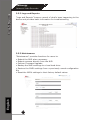
Contents Inside the Installation CD
Adobe Acrobat Reader
Smart Device Search Utility
Pi-Vu Central Basic CMS software
NVR Media Player
User’s Manual
Quick installation Guide
Datasheet
5
SEEnergy
User’s Manual
Network Video Recorder
Product Description
The Embedded Network Video Recorder is designed for use within a
surveillance system, and performs recordings and playbacks pictures
from network cameras in the system. It is a recording device using a
hard disk drive to record camera pictures instead of using video tapes
so that pictures recorded by repeated overwriting will not experience
GHWHULRUDWLRQRIWKHUHFRUGHGSLFWXUHTXDOLW\8SWRIRU695RU
IRU695RUIRU695FDPHUDVFDQEHFRQQHFWHGYLDDQHWwork and it is possible to record their camera pictures. It is possible to
perform the settings or operate the NVR using a web browser installed
on a PC connected to a network, or remote controller. Recorded video
FDQEHSOD\HGEDFNIURPUHPRWHVLWHE\D3&8SWR3&VZHEEURZVHUVFDQDFFHVVWKLVXQLWFRQFXUUHQWO\DQGLWLVSRVVLEOHWRSHUIRUPWKH
settings and operate this unit. The NVR is compatible with most major
brand cameras and its ability to automatically search and fnd the
available cameras on the network can greatly reduce the user effort
when expanding the system.
Advance PTZ Control
Various Types Event Alerts
Pure Web Based Administration
Linux-embedded Operating System
Export Recorded Videos to AVI
Compatible with Major Brand Cameras
High Quality Live/Playback Videos
English
Smart Camera Search
6
SEEnergy
User’s Manual
Network Video Recorder
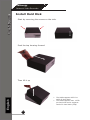
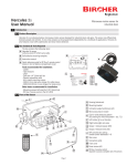
Install Hard Disk
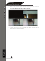
Start by removing the screws on the side:
Push the top housing forward
Then lift it up
English
The NVR supports SATA I or
SATA II hard disks
The NVR supports max. 1.5TB
per hard disk and it supports
total of 2 hard disks (3TB)
7
SEEnergy
User’s Manual
Network Video Recorder
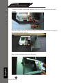
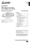
There is a cable connected between the fron LED board and the main
board
You can remove it from the main board or simply put the top housing on
the side like shown below:
English
Next, slide the hard drive into the tray:
8
SEEnergy
User’s Manual
Network Video Recorder
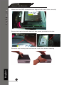
Make sure the SATA connectors are aligned with each other correctly
Secure the hard drive with the tool-less screw provided in the box
English
Place the top housing back and secure it with the bottom housing
9
SEEnergy
User’s Manual
Network Video Recorder
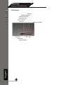
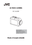
Hardware Illustration (Front)
16 Channel
English
8 Channel
10
SEEnergy
4 Channel
English
User’s Manual
Network Video Recorder
11
SEEnergy
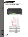
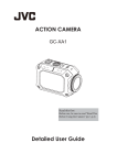
I/O Ports and RS-485 (Rear)
Pin
1
2
3~10
11
12
13
14
15
16
English
User’s Manual
Network Video Recorder
12
Signal
DCIN
GND
Alarm input
Out1
Out2
Out3
Out4
56
56
SEEnergy
User’s Manual
Network Video Recorder
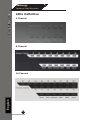
/('V'H¿QLWLRQ
4 Channel
8 Channel
English
16 Channel
13
SEEnergy
User’s Manual
Network Video Recorder
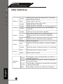
/('V'H¿QLWLRQ
HDD x 2
Green
Solid green when the hard disk is mounted
and being accessed
Red
Solid red for disk fail
Amber
Network
Status
Power
Alarm
Amber
Green
Amber
%OLQNLQJGXULQJ¿UPZDUHXSJUDGH
Green
Shows solid green for normal operation.
%OLQNLQJJUHHQZKHQ¿UPZDUHXSJUDGHLV
done
Red
)ODVKHVUHGIRUIDLOHG¿UPZDUHXSJUDGH
Green
Normal operation
Red
6\VWHPRIISRZHUDGDSWHUUHPDLQVSOXJJHG
LQ
Amber
Blinking amber indicating device is initializing
Red
Blinking when an alarm occurs
None
When alarm is reset
Green
Camera
LED
Amber
Amber
English
Red
14
Solid amber when disk is full
Blinking when recycling
Solid amber for activity on a 1G bps network.
Solid green for activity on a 10/100 Mbps
network.
Solid green, live connected with no event or
recording activity
Blinking amber, manual or event recording is
being performed
Solid amber, schedule or continuous recording
is being performed
Recording is set but no video from camera
SEEnergy
User’s Manual
Network Video Recorder
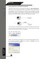
Connect to the NVR
There are various ways you can connect to the NVR and below are
the suggested methods for different network setup:
The NVR is placed in a network with a DHCP server: Connect to
the NVR by using “SEEnergy Device Search” Utility
7KH195LVSODFHGLQDQHWZRUNZLWKRXW'+&3VHUYHURU\RXDUH
FRQQHFWLQJWRLWGLUHFWO\Access NVR with its default IP
Use SEEnergy Device Search Utility
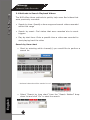
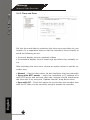
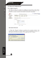
If the NVR is placed in a corporate network or a local area network
where a DHCP server is already presented, install the “SEEnergy Device Search” utility on the CD from a computer that is on the same
network and locate the NVR with its IP address that is assigned by
the top-level DHCP server.
English
To begin, launch the “SEEnergy Deivce Search” utility from the CD
and proceed with the installation:
15
SEEnergy
User’s Manual
Network Video Recorder
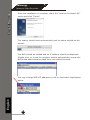
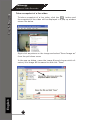
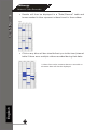
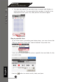
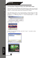
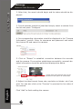
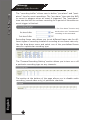
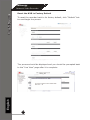
Once the installation is complete, check the “Launch the Search AP”
option and click “Finish”:
The search should start automatically and its status should be displayed:
The NVR should be located and its IP address should be displayed:
Double-click on it and the program should automatically access the
NVR’s web administration page from your default browser
English
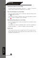
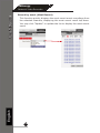
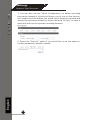
You may change NVR’s IP address by click on the button highlighted
below.
16
SEEnergy
User’s Manual
Network Video Recorder
You will be prompted for the NVR’s login information before proceeding
to change device’s IP address.
You may click on the button highlighted below to perform search again.
Or double-click on any of the search results to access NVR’s web administration page
perform search again
access NVR’s web administration page
English
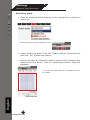
You should be prompted for the NVR’s username and password. Enter its default username “admin” and password “admin” and then
click”OK” to enter the system
17
SEEnergy
User’s Manual
Network Video Recorder
Access NVR with its default IP address
7KH195FRPHVZLWKDSUHFRQ¿JXUHGVWDWLF,3³192.168.101.50”.
However, it is only used when there is no DHCP server presented in
the network. The NVR will turn on its DHCP server function and act
as the DHCP server in the network. To connect to the NVR, use a PC
that is on the same network over a switch or hub, or connect the PC
directly to the NVR using a crossover CAT5 Ethernet cable.
7KH3&WKDWLVFRQQHFWHGGLUHFWO\WRWKH195RUZLWKLQWKHVDPHORFDO
DUHDQHWZRUNVKRXOGUHFHLYHDQ,3IURPLW6LPSO\DFFHVVWKH195
from your web browser with its IP address
English
Again, you should be prompted for the username and password. Enter its default username “admin” and password “admin” and then
click”OK” to enter the system
18
SEEnergy
User’s Manual
Network Video Recorder
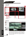
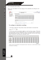
1. Live View
SVR-116
Camera List
PTZ Control
Live Video
Live Video Control Buttons
English
SVR-108
19
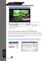
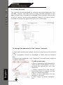
7KHFKDQQHO195FRPHVZLWKDYLGHRVSOLWZLQGRZ
view with one video displays on a larger window. Select a channel from the drop-down menu to display its
video on the larger split window. You can also doubleclick on any of the smaller one to display its video to
the larger window.
SEEnergy
Network Video Recorder
User’s Manual
SVR-104
The “Live View” page provides the following functions:
Retrieve camera’s video stream
Retrieve camera’s status
Perform Live Sequence Viewing
PTZ Control
Perform PTZ Preset Sequence viewing
Perform manual recording
Take snapshot
Receive audio of a video stream
Send audio
Control “Buzzer”
Change web UI display language
English
20
SEEnergy
User’s Manual
Network Video Recorder
1.1 Retrieve camera’s video stream
The camera list is expanded and displayed on the Live View page.
Click “All” to display videos in the
YLGHR PRGH 695 RU YLGHRPRGH695
&OLFNRQD³*URXS´H[*URXS
to display videos from cameras
under that group in quad view
Click on any camera to display
video in single-view mode
1.2 Retrieve camera’s status
The camera list can show each camera’s current status. Each status is represented with different colors and their meanings are explained on the left
Camera is connected
Camera is NOT connected
English
Camera is current performing recording
21
SEEnergy
User’s Manual
Network Video Recorder
1.3 Perform Sequence Viewing
Sequence view is a function that allows you to view multiple video streams from certain cameras in sequence automatically without
having to select them one by one.
To perform sequence view, select “SEQ View” from the upper-left
hand corner
1H[WVHOHFWRQHRUPRUHFDPHUDVRUFDPHUDJURXSVIRUVHTXHQFH
viewing
Then select dwell interval from the drop-down menu
Finally click “Start” to start sequence viewing
* Click “All Channels” to quickly select all available channels and start sequence
view in single-view mode.
Click “All Groups” to quick select all available groups and start sequence view in
quad-view mode
Or simply select the desired channels and press “Start” to start sequence view
English
The “All Group” button is not available in 4Ch NVR as it only has one group
22
SEEnergy
User’s Manual
Network Video Recorder
1.4 PTZ Control
PTZ control provides functions to pan, tilt, zoom a PTZ camera
as well as the ability to adjust camera focus and iris
&DPHUDVWKDWDUHFXUUHQWO\EHLQJVHOHFWHGIRUOLYHYLHZLQJZLOO
be listed in the PTZ drop-down menu. Simply select a camera
then use the PTZ control panel to control the camera
English
The bar shown below allows you to control the pan/tilt speed
23
SEEnergy
User’s Manual
Network Video Recorder
1.5 Perform PTZ Preset Viewing
There are three functions provided in the “Preset” section:
Perform preset point viewing of a particular camera
Auto pan a particular camera
Perform preset point sequence viewing
Preset Point Viewing
Start by selecting a PTZ camera from the drop-down list:
Its available PTZ preset points will be listed in the dropdown list shown below:
English
Select a preset position from the drop-down list and click
“Go to” to move the live view to that position
24
SEEnergy
User’s Manual
Network Video Recorder
Auto Pan Viewing
Start by selecting a PTZ camera from the drop-down list:
Use the Auto Pan control buttons to pan right, left and
stop auto pan
Autopan
Pan Left
Stop pan
* Certain cameras do not support
bi-directional pan movements.
Use the “Autopan” button for
such cameras
Pan right
Preset Point Sequence Viewing
This function allows you to view multiple preset points
from a video of a camera without having to select them
RQH E\ RQH 2QFH \RX KDYH GH¿QHG WKH SUHIHUHG SUHVHW
points in “&KDQQHO&RQ¿JXUDWLRQV” >> “PTZ Setting”
>> “PTZ Sequence” under the “Setup” menu, click
“Start” in the lower-left hand corner in Live View under
“Preset” and the recorder will begin to display videos from
those preset points in sequence automatically until you
click “Stop”
English
“In the Setup page”
25
In the Live View
SEEnergy
User’s Manual
Network Video Recorder
1.6 Live Video Control Buttons
Each live video window comes with control buttons with functions described below:
Take a snapshot of a live video
Turn on/off audio of a live video
6WDUWVWRSUHFRUGLQJRIDOLYHYLGHRPDQXDOUHFRUGLQJ
Audio post function
Full screen view of a live video
English
Display video in its original ratio
26
SEEnergy
User’s Manual
Network Video Recorder
Take a snapshot of a live video
To take a snapshot of a live video, click the
button and
the snapshot of the video will be displayed in a pop up window
shown like below
Right-click anywhere on the image and select “Save Image as”
from the pull-down menu
English
,QWKHSRSXSGLDORJQDPHWKHLPDJH¿OHDQGFKRRVHZKLFKGLrectory the image will be saved to and click “Save”
27
SEEnergy
User’s Manual
Network Video Recorder
Full Screen View of a Live Video
To view a video in full screen, click the
button. To exit full
screen video, double-click anywhere on the video.
Turn On/Off Audio of a Live Video
You can retrieve audio from a particular camera. Simply click
the
button to do so.
The button will show in different color once the audio is turned
on.
Click on it again to turn off audio.
Start/Stop Recording of a Live Video
You can manually start or stop recording of a live video by using
the
button.
The button will show in different color once the recording is
started manually.
Click on it again to stop recording.
Audio post
English
This function allows user to speak from a PC through a microphone and the audio can be played at the camera side if it has
a speaker connected to it.
28
SEEnergy
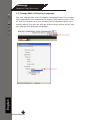
1.7 Change Web UI Display Language
You can change the web UI display language from the current
login username link located at the upper-right hand corner. Click
on the link opens up a new window which displays detail information about the user as well as a drop-down menu which lets
you change the displyay language.
English
User’s Manual
Network Video Recorder
29
SEEnergy
User’s Manual
Network Video Recorder
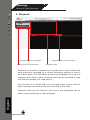
2. Playback
Methods to search playback
Channels to be played back
Playback video control buttons
Playback video
Playback is a function that allows you to play one or more videos that
were previously recorded by a chosen recording method or due to
an event trigger. The NVR offers synchronized playback from up to 4
channels and various types of search methods are provided to help
\RX¿QGWKHIRRWDJH\RXQHHGTXLFNO\
You can turn on or off the audio of a recorded video at your choice if
audio was also recorded during the recording of the video.
English
Playback video can be viewed in full screen and snapshots can be
taken and saved during a video playback.
30
SEEnergy
User’s Manual
Network Video Recorder
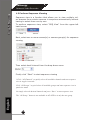
2.1 Methods to Search Playback Videos
7KH195RIIHUVWKUHHPHWKRGVWRTXLFNO\KHOSXVHUV¿QGYLGHRVWKDW
were previously recorded:
Search by time: 6SHFL¿\DWLPHUDQJHDQGVHDUFKYLGHRVUHFRUGHG
ZLWKLQWKDWUDQJH
Search by event: )LQG YLGHRV WKDW ZHUH UHFRUGHG GXH WR HYHQW
WULJJHUV
Play by start time: (QWHUDVSHFL¿FWLPHDYLGHRZDVUHFRUGHGWR
VWDUWSOD\LQJEDFNWKHYLGHR
Search by time chart
6WDUWE\VHOHFWLQJZKLFKFKDQQHOV\RXZRXOGOLNHWRSHUIRUPD
search on:
6HOHFWHGFKDQQHOVZLOOEHPDUNHGLQUHG
English
Select “Search by time chart” from the “Search Method” dropdown list and click “Go” to start the search:
31
SEEnergy
User’s Manual
Network Video Recorder
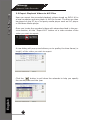
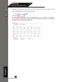
Results will then be displayed in a “Date/Channel” table and
boxes marked in blue represent videos found in those dates:
Click on any blue cell box should direct you to the hour/channel
table if there were multiple videos recorded during that date:
English
* Videos from other cameras that are recorded on
WKHVDPHGDWHZLOODOVREHGLVSOD\HG
32
SEEnergy
User’s Manual
Network Video Recorder
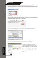
Click on the cell box again will start playing back the videos if
you have reached the end of search results:
English
Videos found from other cameras that were recorded at the
same time will also be played.
33
SEEnergy
User’s Manual
Network Video Recorder
Search by event
6WDUWE\VHOHFWLQJZKLFKFKDQQHOV\RXZRXOGOLNHWRSHUIRUPD
search on:
6HOHFWHGFKDQQHOVZLOOEHPDUNHGLQUHG
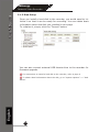
Select “Search by event” from the “Search Method” drop-down list
and click “Go” to start the search:
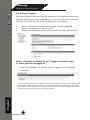
5HVXOWVZLOOWKHQEHOLVWHGOLNHZKDWLVVKRZQEHORZGLVSOD\VWKH
ROGHVWUHFRUGWRSGRZQ&OLFNRQDSDUWLFXODUUHVXOWWRVWDUWWKH
playback:
English
<RXFDQFLOFN³1H[W6HDUFK´WRGLVSOD\WKHQH[W
15 results.
34
SEEnergy
User’s Manual
Network Video Recorder
You may also specify a new start time to search and display results from then on. You can restrict the number of results to be
GLVSOD\HGDWRQFHPD[DQGSHUIRUPWKHVHDUFKDJDLQ
3OD\E\VSHFL¿FWLPH
If you know when a recording was taken place, you may choose the
“Play by start time” from the “Search Method” drop-down list
English
7KHQ\RXZLOOEHSURPSWHGWRHQWHUDVSHFL¿FWLPHDQGGDWHIRUWKH
recorded video.
Use the
35
button to select month, date, and year
SEEnergy
Search by event (Most Recent)
This function quickly displays the most recent event recordings from
the selected channels, displaying the most recent result top down.
You may click “Update” to update the list to display the most recent
result
English
User’s Manual
Network Video Recorder
36
SEEnergy
User’s Manual
Network Video Recorder
2.2 Export Playback Videos to AVI Files
User can export the recorded playback videos stored on SVR-116 to
DORFDOFRPSXWHUDQGVDYHWKHPLQ$9,¿OHIRUPDW7KH¿OHVFDQWKHQ
be played on the PC by a 3rd party media player such as VLC player
or Windows Media player.
Once you locate the recorded videos with steps described in the previous section, hit the “Export AVI” button on a video window of the
video you wish to export.
$QHZGLDORJZLOOSRSXSDQGDOORZV\RXWRVSH¿F\WKHWLPHIUDPHRU
OHQJWKRIWKHYLGHR\RXZLVKWRH[SRUW
English
Click the
button to pull down the calendar to help you specify
the month, date and the year
37
SEEnergy
User’s Manual
Network Video Recorder
Specify the starting and ending hours of the video by entering numbers in the text boxes
+LWWKH³6WDUW´EXWWRQWRVWDUWH[SRUWLQJ7KH¿OHZLOOEHDXWRPDWLFDOO\
named and saved under the C:\ partition
<RXZLOOEHQRWL¿HGRQFHWKHSURFHVVLVFRPSOHWHGVXFFHVVIXOO\
7KHH[SRUWHG$9,¿OHZLOOEHVDYHGXQGHUWKH&SDUWLWLRQ
English
* ffdshow is required in order to
SOD\WKHH[SRUWHG$9,¿OHZLWK:LQGRZV0HGLD3OD\HU<RXFDQJHWLWDW
³KWWSVRXUFHIRUJHQHWSURMHFWVIIGVKRZWU\RXW´WRGRZQORDGWKH³IIGVKRZBEHWDBUHYB
exe”
38
SEEnergy
User’s Manual
Network Video Recorder
2.3 Play Export Playback Videos with NVR Media Player
You can also use the SEEnergy NVR Media Player to play the exported
$9,¿OHV7KLVFDQVDYH\RXWKHWURXEOHRILQVWDOOLQJWKLUGSDUW\PHGLD
player or codecs when playing the exported AVI videos.
The NVR Media Player will be automatically installed after the CMS
software is installed. You can launch the player under “Start” >> “All
Programs” >> “SEEnergy Corp” >> “Pi-Vu Central Basic” >> “NVR
Media Player”
Click “Open” >> “AVI File”
/RFDWH WKH H[SRUWHG $9, ¿OH DQG FOLFN ³RSHQ´ QRUPDOO\ XQGHU
³&?([SRUW)ROGHU´
English
The video will then start playing
39
SEEnergy
User’s Manual
Network Video Recorder
video play control bar
Volume Control
video play control buttons:
5HZLQG3DXVH3OD\6WRS1H[W)UDPH)DVW)RUZDUG
Screenshot/Display OSD
video play time
$XGLR&RQWUROFOLFNWRHQDEOHGLVDEOH
Video Play Speed
2.4 Open Event Snapshot images with NVR Media Player
The NVR sends snapshots that are taken when an event occurs to a
destined FTP server or mail recepient. These type of snapshot images
DUHVDYHGLQDSURSULHWDU\LPDJH¿OHIRUPDWKLRUSLDQGFDQRQO\EH
opened by the NVR media player.
English
To do so, Select “Open” from the top menu then select “Image File”.
$QHZGLDORJVKRXOGEHGLVSOD\HGZKLFKOHWV\RXORFDWHWKHLPDJH¿OH
40
SEEnergy
User’s Manual
Network Video Recorder
3. System Setup
6\VWHP&RQ¿JXUDWLRQV
7KH³6\VWHP&RQ¿JXUDWLRQV´SDJHSURYLGHVXVHUVRSWLRQVWRVHWXSWKH
GHYLFHTXLFNO\DQGSURSHUO\$IWHUSURSHUO\FRQ¿JXULQJDOOVHWWLQJVLQ
all the sub-pages, users should expect a fully working network video
recorder that is ready to manage cameras on the network. We will
VWDUWE\FRQ¿JXULQJLWVQHWZRUNVHWWLQJVWRPDNHVXUHLWZRUNVFRUrectly in your network. Next, we will help you adjust the system time
so videos will be recorder with correct timestamp. To better secure
the system for unwanted disturbance, we will guide you on setting up
user’s account and privileges to prevent settings gets altered by users other than the system administrator. Lastly, we will tell you what
you should expect after installing a hard disk and how to prepare the
hard disk for the video recording.
English
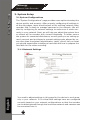
3.1.1 Network Settings
You need to adjust settings in this page for the device to work propHUO\LQ\RXUQHWZRUN,WLVFULWLFDOWKDWVHWWLQJVKHUHDUHFRQ¿JXUHG
FRUUHFWO\EDVHGRQ\RXUQHWZRUNFRQ¿JXUDWLRQVVRWKDWWKHUHFRUGHU
can be administered through the local area network and cameras can
be connected from it.
41
SEEnergy
User’s Manual
Network Video Recorder
By default, the recorder is set to obtain IP address from DHCP server,
LWVKRXOGEHVXI¿FLHQWLQPRVWQHWZRUNHQYLURQPHQWVDQGPRVWOLNHO\
you should not need to alter anything in this page. To locate the
recorder, simply use the SEEnergy IP Utility with steps described in
page 12.
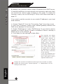
If you wish to set the recorder to use a static IP address in your local
area network,
1. Choose “Static IP” from the “Connection Type” drop-down menu
2. Enter the IP address, subnet mask, default gateway address and
DNS server address for the recorder
3. Enable “DHCP Server” under “DHCP Server” if you wish to use the
recorder as a DHCP server, or leave it disabled if there is already a
DHCP server in the network
4. Click Apply for the settings to take effect
The recorder can detect
the presence of a DHCP
VHUYHU XSRQ VWDUWXS ,W
sets itself to use static
IP address if there is no
'+&3 VHUYHU FXUUHQWO\
presented in the network.
,WV '+&3 VHUYHU IXQFtion is also turned on at
WKH VDPH WLPH WR DVVLJQ
IP addresses to cameras
that are later connected
to the network
R <RX FDQ PDQXDOO\ WXUQ
RIIWKH'+&3VHUYHUIXQFWLRQ LI \RX ZLVK WR XVH D
VHSDUDWH'+&3VHUYHU
English
&KDQJHWKHUHFRUGHU¶V,3DGGUHVVZRXOGUHTXLUHWKHUHFRUGHUWRUHVWDUW
5HVWDUW WKH GHYLFH XQGHU ³V\VWHP 2SWLRQV´ !! ³0DLQWHQDQFH´ IRU WKH
VHWWLQJVWRWDNHHIIHFW
42
SEEnergy
User’s Manual
Network Video Recorder
3.1.2 Time and Date
Set the time and date by selecting the time zone according to your
location. It is imperative that you set the recorder’s time correctly to
avoid the following errors:
,QFRUUHFWGLVSOD\WLPHIRUSOD\EDFNYLGHRV
,QFRQVLVWHQWGLVSOD\WLPHRIHYHQWORJVDQGZKHQWKH\DFWXDOO\RFcur
After selecting the time zone, choose an option below to set the recorder time
English
Manual±8VHWKHGURSGRZQOLVWDQGFRQ¿JXUHWKHWLPHPDQXally
Sync with NTP server – enter the hostname or IP address of a
valid NTP server and set how often the recorder should synchronize
the time with it by using the “Update interval” drop-down menu
Sync with PC – Check this option to synchronize the recorder time
with the PC that you are currently using to access the recorder
43
SEEnergy
User’s Manual
Network Video Recorder
3.1.3 User Account
The recorder can be accessed by multiple users simultaneously. You
can add, remove, and edit users by using options provided in this
page to keep user information organized. Each recorder comes with
a built-in “admin” account with password “admin”. It’s highly recommended to change the password upon your initial login.
To change the password of the “admin” account:
English
1. Click and highlight the “admin” account in the account list and click
“Edit”
2. Its information should be displayed in “User Account Information”
(QWHUDQHZSDVVZRUGLQWKH³3DVVZRUG´¿HOGDQGHQWHULWDJDLQLQ
³&RQ¿UP3DVVZRUG´
To add a new user:
44
(QWHr a username and password in
“User Account Information”. All othHU ¿HOGV DUH RSWLRQDO IRU \RXU RZQ
reference.
6Hlect a group from the “Group”
drop-down menu to assign the new
user to a particular group
(nter a short description for the
account if you wish
&OLFN ³$SSO\´ WR ¿QLVK FRQ¿JXUDtion
SEEnergy
User’s Manual
Network Video Recorder
3.1.4 Group Privilege
Group Privilege is where you can create multiple customized access
policies for situations if you need the recorder to be accessed by users other than the administrator. You can do so by creating a group,
DQGWKHQUHPRYHDFFHVVSULYLOHJHVIRUFHUWDLQFRQ¿JXUDWLRQSDJHVRU
cameras. Users that are created and assigned to this group will have
limited access instead of full administration rights.
7KHUHFRUGHUFRPHVZLWKVHYHQEXLOWLQJURXSVDQG¿YHEXLOWLQSULYLOHJHSUR¿OHVH[FHSWWKH³DGPLQ´DQGWKH³JXHVW´DFFRXQWVWKHRWKHU
¿YHJURXSVDUHIXOO\FXVWRPL]DEOHRU\RXFDQVLPSO\DVVLJQDJURXS
ZLWK RQH RI WKH GHIDXOW SULYLOHJH SUR¿OHV <RX FDQ KRZHYHU DVVLJQ
more than one users to the “admin” account if you wish to do so. The
guest account comes with a “view-only” privilege in the “Live View”
page, and users in this group do not have the power to make any
changes in the “Live View” page or have access to pages other than
the “Live View” page.
To create a group, select a group from the “Group” drop-down
menu
English
You can change the group name by clicking the “Change Group Name”
button. A text box will be displayed for you to enter the new group
name
45
SEEnergy
Choose what type of privilege you would like this group to have from
the “Privilege Type” drop-down menu
Its access privilege will then be displayed. You can alter its settings
by allowing or denying access to other cameras using the checkboxes
instead of accepting the defaults
English
User’s Manual
Network Video Recorder
46
SEEnergy
User’s Manual
Network Video Recorder
3.1.5 Disk Setup
Once you install a hard disk to the recorder, you would need to initialize it so that it can be ready for recording. You can obtain basic
information about the disk you installed in this page
To initialize it, simply click the “Format” button
You can also connect external USB thumb drive to the recorder for
¿UPZDUHXSJUDGH
)RULQVWUXFWLRQVWRLQVWDOODKDUGGLVNWRWKHUHFRUGHUUHIHUWRSDJH
7RREWDLQGHWDLOLQIRUPDWLRQDERXWWKHGLVNJRWR³6\VWHP2SWLRQV´!!³'LVN
English
Status”
47
SEEnergy
User’s Manual
Network Video Recorder
&KDQQHO&RQ¿JXUDWLRQV
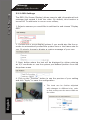
3.2.1 Add a Camera
The NVR provides two options for adding a new camera. Users have
WKHRSWLRQWROHWWKHUHFRUGHUDXWRPDWLFDOO\¿QGWKHFDPHUDVRULWLV
possible to enter camera’s information and add it manually.
Automatic Search:
English
1. Click the “Search” button to perform the camera search. You
should be prompted to install Active Control component in order for
the search to function properly. Go ahead and click “Install”
48
SEEnergy
User’s Manual
Network Video Recorder
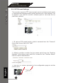
2. After that, the search should begin and its status should be displayed:
3. Found cameras should be listed and simply select a camera from
WKHOLVWDQGSUHVV³&RQ¿JXUH´
4. Its corresponding information should be displayed in the “Camera
Information” section. Enter its username and password and select
the channel ID and name the camera.
5. Click on “Detect” to establish connection between the recorder
and the camera. If connection establishes successfully, camera’s detailed information should be polled and displayed as below
$XGLRIURPWKLVFKDQQHOZLOOQRWEH
recorded if this option is unchecked
English
6. Adjust its video format, frame rate, resolution or bitrate…etc if you
wish. You can also click on the “Preview” to preview the live video of
the camera.
&OLFN³$GG´WR¿QLVKDGGLQJWKHFDPHUD
49
SEEnergy
Network Video Recorder
User’s Manual
If cameras are marked with “*” in the search result, it means those cameras
DUHDOUHDG\FRQ¿JXUHGDQGFRQQHFWHGWR695
Add a camera manually
Simply follow the instruction described above but instead of
using the “Search” function, enter the camera’s IP address and credential in the “Camera Information” manually, then follow step 5 ~6
described above.
2.
1.
English
Enter manually
50
SEEnergy
User’s Manual
Network Video Recorder
3.2.2 OSD Settings
7KH26'2Q6FUHHQ'LVSOD\DOORZVXVHUVWRDGGLQIRUPDWLRQDOWH[W
message and embed it onto the video. By default, this function is
turned off. To add texts to one or more videos,
1. Select a camera you would like to add text to and choose “Display
OSD”
2. Choose one or more display options if you would also like the recorder to automatically embed the system time or the frame rate for
you. Or simply choose to display a custom message of your own
1H[W GH¿QH ZKHUH WKH WH[W ZLOO EH GLVSOD\HG E\ HLWKHU HQWHULQJ
DQ;<FRRUGLQDWHRUXVHWKHV\VWHPSUHGH¿QHGSRVLWLRQIURPWKH
drop-down menu
4. Click on the “Preview” button to see the preview of your setting
DQGFOLFN³$SSO\´WRVDYHWKHFRQ¿JXUDWLRQ
English
7KH WH[WV FDQ EH IXUWKHU DGMXVWHG
ZLWK FKDQJHV WR GLIIHUHQW VL]H FRORU
RUIRQWVRWKH\FDQEHPRUHYLVLEOHRQ
WKHYLGHR
51
SEEnergy
User’s Manual
Network Video Recorder
3.2.3 PTZ Preset Settings
The recorder supports PTZ cameras and can set multiple preset points
or retrieve and manage preset points that are set in the camera. This
is helpful if you need to monitor multiple spots in one area from a
particular camera.
1. To set up PTZ preset points, select a camera from the “Camera”
drop-down menu and click “Add”
2. Select a position number for the preset point from the “Position
1XPEHU´GURSGRZQPHQXDQG¿OOLQDQDPHLQWKH³3RVLWLRQ1DPH´
¿HOGIRUHDVLHULGHQWL¿FDWLRQ
English
8VHWKH37=FRQWUROSURYLGHGLQWKHFRQ¿JXUDWLRQSDJHWRVHWWKH
preset point
52
SEEnergy
Ultimately, you can choose to make this preset point a “Home” point
among all other preset points, as well as making the camera to move
to this particular point when an event is triggered.
³0RYH+HUHZKHQ(YHQW7ULJJHU´,QRUGHUIRUWKLVIXQFWLRQWRZRUNSURSHUO\
SOHDVHDOVRFRPSOHWHFRQ¿JXUDWLRQLQ³(YHQW&RQ¿JXUDWLRQ´!!³(YHQW7ULJJHU´
English
User’s Manual
Network Video Recorder
53
SEEnergy
User’s Manual
Network Video Recorder
3.2.4 PTZ Preset Sequence
2QFH\RXKDYHPXOWLSOHSUHVHWSRLQWVGH¿QHGIRUDFDPHUDLWLVFRQvenient for monitoring to set up the sequencing viewing among those
preset point and let the recorder automatically switch between them
for you.
7RFRQ¿JXUHSUHVHWVHTXHQFHIRUDFDPHUDVHOHFWDFKDQQHOIURPWKH
“Channel” drop-down menu
The available preset points should be listed in “Camera Presets” section
Pick the ones you like for sequence viewing and press the “->” button
to move them to the “Preset Sequence” section, then use the up and
down buttons to adjust their sequencing positions.
Finally, select a dwell time from the drop-down menu and click “ApSO\´WRVDYHWKHFRQ¿JXUDWLRQ
English
7RVWDUWSUHVHWVHTXHQFHYLHZLQJFKHFNSDJHIRULQVWUXFWLRQV
54
SEEnergy
User’s Manual
Network Video Recorder
3.2.5 E-Map Setting
3.2.5.1 Local Map Setting
E-Map monitor is a function that alerts users whenever there is an event
WULJJHUHG HJ PRWLRQ GHWHFWHG IURP D FDPHUD ZLWK D JHRJUDSKLFDO
perspective. With this function, users can quickly identify which camera
has detected an unusual event and where this event is happening. This
function works by incorporating the event detection function as well as
the recording function, which, as a result, helps users take all the necessary actions when an unusual event occurs.
English
To replace the map, click “Browse” button to locate the new map image
¿OHIURPWKHORFDO3&DQGWKHQFOLFN³8SORDG´
2QO\-3*31*DQG*,)¿OHIRUPDWVDUHVXSSRUWHGZLWK¿OHVL]HXQGHU.%
55
SEEnergy
User’s Manual
Network Video Recorder
7KHQFOLFNDQGGUDJWKHFDPHUDLFRQWRPRYHWKHFDPHUDWRGH¿QHLWV
location.
Access the E-Map Monitor page from the upper-right hand corner
menu
English
When the NVR receives an event triggered from any of the cameras,
their videos will be displayed on the E-Map and you can double-click on
the video to enlarge it
56
SEEnergy
User’s Manual
Network Video Recorder
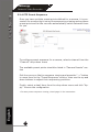
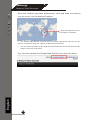
3.2.5.2 Google Map Setting
The Google Map monitor is a similar function to the aforementioned
E-Map monitor. It is useful if you are managing multiple cameras
from different locations.
7R FRQ¿JXUH ORFDWLRQV RI HDFK FDPHUD ¿UVW GHWHUPLQH WKH ORFDWLRQ
you’d like to place the camera to on the map. You can do so by:
1. Zoom in to a smaller area by using the zoom control bar on the
map
2. Zoom in to a smaller area by using the mouse scroll button
English
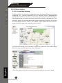
<RXFDQDOVRJRWRDVSHFL¿FSODFHRQWKHPDSE\HQWHULQJLWVDGGUHVV
RUWKHQDPHRIWKHSODFHLQWKH³$GGUHVVRUSODFHVRILQWHUHVW´¿HOG
57
SEEnergy
User’s Manual
Network Video Recorder
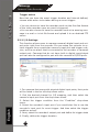
Once the location has been determined, click and drag the camera
icon to move it to the desired location:
&OLFNDQGGUDJWKHLFRQWR
UHDUUDQJHLWVORFDWLRQ
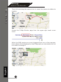
7KH*RRJOH0DS0RQLWRUUHTXLUHVDFWLYH,QWHUQHWFRQQHFWLRQDQGFDQQRWEH
XVHGLQFRQMXQFWLRQZLWKWKHUHJXODU(0DSPRQLWRUIXQFWLRQ
<RXFDQFOLFNDQ\ZKHUHRQWKHPDSDQGKROGGRZQWKHPRXVHOHIWEXWWRQWKHQ
GUDJWRPRYHWKHPDSLWVHOI
English
You can then access the Google Map Monitor from the top menu:
58
SEEnergy
User’s Manual
Network Video Recorder
(YHQW&RQ¿JXUDWLRQV
7KH³(YHQW&RQ¿JXUDWLRQV´VHFWLRQDOORZVXVHUVWRGH¿QHFRQGLWLRQV
that constitute an event, its corresponding trigger action and when it
will be triggered. Such setting can reduce the management overhead
and notify the administrator only when it’s necessary.
3.3.1 General Settings
7KH JHQHUDO VHWWLQJV VHFWLRQ FDQ KHOS \RX TXLFNO\ FRQ¿JXUH ZKHQ
an event is triggered, how often events are triggered and the corresponding actions when events are triggered.
English
6WDUWWKHHYHQWFRQ¿JXUDWLRQE\GH¿QLQJWKHJHQHUDOVHWWLQJV
DH¿QHZKHQDQHYHQWZLOOEHWULJJHUHG
&hoose “Always” or “Only during…” under “Event Trigger Duration”
)RUWKH³2QO\GXULQJ«´RSWLRQFKRRVHWKHGD\VE\XVLQJWKHFKHFNER[DQGWKHQGH¿QHWKHWLPHUDQJHLQWKRVHGD\VLQWKH³6WDUW7LPH´
DQG³(QG7LPH´¿HOGVWKDW\RXZRXOGOLNHWKHHYHQWWULJJHUIXQFWLRQ
to be enabled.
How often an event is triggered
6HW D WLPH LQWHUYDO XQGHU ³(YHQW 7ULJJHU ,QWHUYDO´ WR GH¿QH KRZ
often events are triggered
59
SEEnergy
User’s Manual
Network Video Recorder
Trigger action
NoZWKDW\RXKDYHWKHHYHQWWULJJHUGXUDWLRQDQGLQWHUYDOGH¿QHG
choose what action to be taken during an event trigger:
<RXFDQFKRRVHWRKDYHWKHUHFRUGHUVHQGRXWWKH¿UVWIHZIUDPHV
of the video recorder upon an event is triggered
<RXFDQDOVRFKRRVHWRKDYHWKHUHFRUGHUVHQGRXWDZDUQLQJPHVVDJHLQHPDLORULQW[W¿OHIRUPDWDQGXSORDGLWWRDQGHVWLQHG)73
server
3.3.2 I/O Settings
English
This function allows users to manage camera’s digital input and output ports right from the recorder. You can setup the recorder to receive triggers from a particular camera’s input port and trigger a device, such as an alarm that is connected to the recorder or camera’s
output port. Cameras that do not have built-in digital input/output
SRUWFDQDOVREHFRQ¿JXUHGWRSDLUZLWKWKHUHFRUGHU¶V','2SRUWV
1. For cameras that come with physical digital input ports, their ports
will be listed in the far left drop-down menu.
2. Pick the desired channel for I/O mapping, and then select the
camera’s input port from the drop-down menu.
3. Select the trigger condition from the “Condition” drop-down
menu.
4. Select the recorder’s input port if you would also like to use the
recorder’s input port for event trigger. And then select the trigger
condition as well.
5. NH[WVHOHFWWKHUHFRUGHU¶VRXWSXWSRUWDQGGH¿QHLWVWULJJHUVWDWH
6. FiQDOO\GH¿QHWKHWULJJHUGXUDWLRQ
60
SEEnergy
User’s Manual
Network Video Recorder
7KHUHFRUGHUGRHVQRWFRQWUROFDPHUD¶VLQSXWRURXWSXWSRUWVLQDZD\WROHW
\RXSDLUUHFRUGHULWVHOIZLWKDFDPHUD¶VLQSXWRURXWSXWSRUWIRUHYHQWUHFHLYLQJRU
WULJJHULQJ
The recoUGHURQO\DFWVDVDPHGLXPIRUSDLULQJXSLQSXWRXWSXWSRUWVEHWZHHQ
cameras and the recorder.
2QO\FRQQHFWHGFDPHUDVZLOOEHGLVSOD\HGLQWKHOLVW
6RPH FDPHUDV RQO\ DOORZ RQH WULJJHU VRXUFH EH FRQ¿JXUHG DW D WLPH HJ
LI WKH FDPHUD KDV WKH PRWLRQ GHWHFWLRQ IXQFWLRQ WXUQHG RQ LWV GLJLWDO LQSXW ZLOO
EHGLVDEOHGDQGYLFHYHUVD8QGHUVXFKFLUFXPVWDQFHLI\RXVHWWRXVHFDPHUD¶V
GLJLWDOLQSXWSRUWDVWKHHYHQWWULJJHUVRXUFH\RXZLOOQRWEHDEOHWRVHOHFWPRWLRQ
GHWHFWLRQDVWKHWULJJHUVRXUFHIRUWKLVFDPHUDXQGHU³(YHQW&RQ¿JXUDWLRQV´!!
³(YHQW7ULJJHU´VHWXSSDJH
English
7KHLPDJHVWKDWDUHXSORDGHGWRWKHGHVWLQHG)73VHUYHURUHPDLOHGWRDGHVWLQHGPDLOUHFHSLHQWDUHLQWKHLURZQSURSULHWDU\LPDJH¿OHIRUPDWKLRUSL
ZKLFKFDQRQO\EHRSHQHGE\WKH195PHGLDSOD\HU)RUGHDLOVSOHDVHUHIHUWRSDJH
61
SEEnergy
User’s Manual
Network Video Recorder
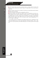
3.3.3 Event Servers
Event servers are to be used with event trigger actions. In case of
unusual motion detected by the camera or a disk failure, the recorder
FDQ VHQG QRWL¿FDWLRQ ZLWK WKH DFFHSWDEOH IRUPDW LPDJHW[W WR D
GHVWLQHGHYHQWVHUYHUDFFRUGLQJWRWKHFRQ¿JXUDWLRQ
&RQ¿JXULQJDQ)73VHUYHU
To add an FTP server,
English
1. Start by giving a name to the server that you are adding to the
recorder
2. Enter the hostname or the IP address of the FTP server
(QWHUWKHFRPPXQLFDWLRQSRUWRIWKH)73VHUYHUXVXDOO\SRUW
62
SEEnergy
User’s Manual
Network Video Recorder
4. Enter the username and password of the FTP server if it’s required
5. Check “Use Passive Mode” if it’s required or leave it unchecked to
use active mode
6. Click “Test” to verify if all information is entered correctly and the
connection to the FTP server can be established successfully
7. Click “Add” for the settings to take effect
,I\RXZLVKWRHGLWUHPRYHHQDEOHGLVDEOHDQ)73VHUYHUFOLFNWRKLJKOLJKWRQH
English
IURPWKHSUR¿OHOLVWDQGFKRRVHWKHFRUUHVSRQGLQJDFWLRQEXWWRQFKHFNER[
63
SEEnergy
User’s Manual
Network Video Recorder
&RQ¿JXULQJDQ6073VHUYHU
English
1. Enter the hostname or the IP address of the SMTP server
2. Enter the port of the SMTP server
6SHFLI\WKHVHQGHU¶VQDPHLQWKH³6HQGHU¶VQDPH´¿HOG
4. Enter the sender’s e-mail address
5. Check “Enable Authentication” and enter the username and password of the SMTP server and as it requires authentication
6. COLFN³$SSO\´WRVDYHWKHFRQ¿JXUDWLRQ
64
SEEnergy
User’s Manual
Network Video Recorder
3.3.4 Event Triggers
:HKDYH¿QLVKHGGH¿QLQJKRZDQHYHQWZLOOEHWULJJHUHGDQGZKLFK
VHUYHUV ZLOO EH UHFHLYLQJ QRWL¿FDWLRQV LQ WKH SUHYLRXV WZR VHFWLRQV
QRZZHFDQ¿QLVKXSWKHHYHQWFRQ¿JXUDWLRQE\VHWWLQJ
ZKLFKFKDQQHOVZLOOKDYHHYHQWWULJJHUIXQFWLRQHQDEOHG
:KDWLVFRQVLGHUHGWREHDQHYHQW
:KHUHWKHZDUQLQJVZLOOEHVHQWWRDQGKRZWKH\ZLOOEHVHQW
Select Channels to Enable Event Trigger and which type
of event should be triggered
Use the checkbox to enable event trigger on the desired
channels
English
2QFHPRWLRQGHWHFWLRQLVHQDEOHGLQWKLVSDJHSOHDVHFRQ¿JXUHWKHPRWLRQDUHD
DQGHQDEOHPRWLRQGHWHFWLRQLQWKHFRUUHVSRQGLQJFKDQQHOVFDPHUDV7KH195
RQO\GHWHFWVWKH¿UVWPRWLRQDUHDVHWLQWKHFDPHUD7KH195UHFRJQL]HVWKH¿UVW
PRWLRQDUHDE\LWV,'QXPEHUVHWLQWKHFDPHUD
65
SEEnergy
User’s Manual
Network Video Recorder
'H¿QHZKLFKV\VWHPHYHQWVVKRXOGWULJJHUWKHUHFRUGHUWRVHQG
RXWQRWL¿FDWLRQV
'H¿QHKRZWKHQRWL¿FDWLRQVZLOO EHVHQWDQGZKHUHWKH\ZLOO EH
sent to
English
(YHQWWULJJHUPD\QRWZRUNIRUFDPHUDVWKDWDUHSODFHGRXWVLGHRI\RXUORFDO
QHWZRUNRURQWKH,QWHUQHWXQWLOWKH³83Q33RUW)RUZDUGLQJ´LVHQDEOHGLQERWK
the NVR and the router.
66
SEEnergy
User’s Manual
Network Video Recorder
5HFRUGLQJ&RQ¿JXUDWLRQV
7KH³UHFRUGLQJFRQ¿JXUDWLRQV´JLYHVXVHUVWKHRYHUDOOFRQWURORIKRZ
and when a recording is performed and the quality of different types
of recordings performed on each channels. It can help the recorder to
RSHUDWHZLWKVXI¿FLHQWV\VWHPUHVRXUFHE\SHUIRUPLQJUHFRUGLQJRQO\
when it’s necessary with adjustable recording frame rate.
3.4.1 General Settings
<RXFDQGH¿QHWKHIROORZLQJLQ³*HQHUDO6HWWLQJV´
3UH$ODUP3RVW$ODUPUHFRUGLQJOHQJWK
5HFRUGLQJIUDPHUDWH
(QDEOHGLVDEOHGLIIHUHQWUHFRUGLQJW\SHVRQGLIIHUHQWFDPHUDV
Enable/disable audio recording
English
67
SEEnergy
User’s Manual
Network Video Recorder
7KH³UHFRUGLQJEXIIHU´DOORZVXVHUWRGH¿QH³SUHDODUP´DQG³SRVW
alarm” time for event recordings. The “pre-alarm” time sets the NVR
to record in advance when an event is triggered. The “post-alarm”
time sets the NVR to continue recording for a period of time after an
HYHQWWULJJHULV¿QLVKHG
7KH³3UHDODUP´IXQFWLRQRQO\
works when the “Continueous”
UHFRUGLQJLVDOVRDFWLYDWHG
Recording frame rate allows you to set different frame rate for different types of recording instead of recording at one frame rate only.
8VH WKH GURSGRZQ PHQX DQG VHOHFW RQH RI WKH SUHGH¿QHG IUDPH
rates for a particular recording type
The “Camera Recording Setting” section allows you to turn on or off
a particular recording type on any channels.
English
The section at the bottom of the page allows you to disable audio
UHFRUGLQJUHFRUGYLGHRRQO\RISDUWLFXODUFKDQQHOV
68
SEEnergy
User’s Manual
Network Video Recorder
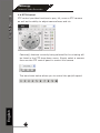
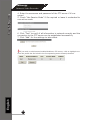
3.4.2 Schedule Recording
+HUH\RXFDQGH¿QHWKHWLPHUDQJHRIWKHVFKHGXOHUHFRUGLQJIRUDOO
channels.
7RFRQ¿JXUHDVFKHGXOHUHFRUGLQJ
8VHWKH³&KDQQHO´GURSGRZQPHQXDQGVHOHFWDFDPHUD¿UVW
2. You can use the schedule table to set the time range. Click the
cell boxes then move horizontally lets you set what hours to perform
recording during a day. Click and move vertically lets you set what
GD\VWRSHUIRUPUHFRUGLQJDWDVSHFL¿FWLPH
(DFKFHOOER[UHSUHVHQWVPLQXWHVRIWLPH&OLFNRQHRUPRUHER[HVWRRPLW
English
FRQVHFXWLYHUHFRUGLQJ
69
SEEnergy
User’s Manual
Network Video Recorder
<RX FDQ DOVR XVH WKH ³4XLFN &RQ¿JXUDWLRQ´ WR GH¿QH UHFRUGLQJ
time range instead of clicking cell boxex one by one on the time table. Simply check what days you would like to perform recording and
specify the recording duration by either choosing “All Day” or enter a
VWDUWDQGHQGWLPHIRUVSHFL¿FUHFRUGLQJGXUDWLRQ
English
4. Select the “Copy to” option if you would like to set the same recording schedule to another camera.
70
SEEnergy
3.5 System Options
System Options gives users a glance of the overall system status and
DOORZVXVHUVWRSHUIRUPPDLQWHQDQFHWDVNVVXFKDVXSJUDGLQJ¿UPware, restore/backup device settings or reboot device ….etc.
3.5.1 Device Information
The “Device Information” provides the general information of the
GHYLFH VXFK DV ¿UPZDUH YHUVLRQ DQG V\VWHP WLPH ,W DOVR SURYLGHV
information of the current network settings and status.
English
User’s Manual
Network Video Recorder
71
SEEnergy
User’s Manual
Network Video Recorder
3.5.2 Logs and Reports
“Logs and Reports” keeps a record of what’s been happening to the
device and provides basic information for troubleshooting
3.5.3 Maintenance
English
“Maintenance” provides functions for users to:
5Hboot the NVR when necessary
5HERRWFDPHUDVGLUHFWO\IURPWKH195
3HUIRUP)LUPZDUH8SJUDGH
%DFNXSWKH195¶VVHWWLQJVWRDORFDOKDUGGULYH
5HVWRUH WKH 195¶V VHWWLQJV IURP D SUHYLRXVO\ VDYHG FRQ¿JXUDWLRQ
¿OH
5eset the NVR’s settings to their factory default values
72
SEEnergy
User’s Manual
Network Video Recorder
Reboot the NVR
5HERRW WKH 195 DIWHU \RX XSORDG D QHZ ¿UPZDUH <RX ZRXOG QHHG
WRPDQXDOO\UHERRWWKHV\VWHPIRUWKHQHZ¿UPZDUHWRWDNHHIIHFW
Such process would prevent a recording from getting interrupted because the system would not automatically reboot itself after the new
¿UPZDUHLVORDGHGRQWRWKHUHFRUGHU
6LPSO\ FOLFN ³5HVWDUW´ WR EHJLQ WKH UHERRW SURFHVV DQG FRQ¿UP WKH
action:
English
The restart process should be displayed and you should be prompted
back to the “Maintenance” page after it is complete:
73
SEEnergy
User’s Manual
Network Video Recorder
Reset the NVR to Factory Default
To reset the recorder back to its factory default, click “Default” button and begin the proces:
English
The process should be displayed and you should be prompted back
to the “Live View” page after it is complete:
74
SEEnergy
User’s Manual
Network Video Recorder
3.5.4 DO Status
This is where you can get the current status of the SVR-116 digital
output ports. You can also change their status from this page.
3.5.5 Disk Status
English
“Disk Status” gives you a more detailed information of the hard drive
that is currently installed in the NVR.
75
SEEnergy
User’s Manual
Network Video Recorder
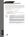
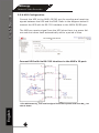
836&RQ¿JXUDWLRQ
Connect the UPS to the NVR’s DI/DO port for sending and receiving
signals between the UPS and the NVR. Refer to the diagram below to
connect the UPS with its RS-232 interface to the NVR’s DI/DO port.
The NVR can receive signal from the UPS when there is a power failure and shut down itself automatically within a period of time.
Connect UPS with its RS-232 interface to the NVR’s IO port:
English
* The NVR uses DI_1 to receive signal from UPS system and uses DO_1 to
shut it down.
76
SEEnergy
EN/MV15/01272010/001
User’s Manual
Network Video Recorder
English
SEEnergy Corp.
4F, No.61, Dongsing RD.,
Taipei 110, Taiwan, R.O.C.
7HO
)D[
E-mail: [email protected]
www.seenergy.com.tw
Connecting Digital Vision
©2007, SEEnergy Corp. The SEEnergy logo is a registered trademark of SEEnergy Corp. All other company names and products
77
DUHWUDGHPDUNVRUUHJLVWHUHGWUDGHPDUNVRIWKHLUUHVSHFWLYHFRPSDQLHV7KHVSHFL¿FDWLRQLVVXEMHFWWRFKDQJHZLWKRXWSULRUQRWLFH
SEEnergy endeavors to ensure that the information in this document is correct and faily stated but does not accept liability for any
error or omissions.