1
Application
This manual has been issued by Canon Inc. for qualified persons to learn technical theory, and
repair of the products.
Corrections
This manual could include typographical errors or technical inaccuracies due to improvements or
changes in the products. When changes occur in applicable products or in the content of this manual,
Canon will release service manual report as the need arises. In the event of major changes in the
contents of this manual over a long or short period, Canon may issue new editions of this manual.
The following paragraph does not apply to any countries where such provisions are inconsistent
with local law.
Trademarks
The product names and company names described in this manual are the registered trademarks of
the individual companies.
Copyright
This manual is copyrighted with all rights reserved. Under the copyright laws, this manual may not
be copied, reproduced, published (including on the World Wide Web) or translated into another
language, in whole or in part, without the written consent of Canon Inc..
Copyright © 2002 by Canon Inc.
CANON INC.
Digital Imaging Products Service Dept.
30-2, Shimomaruko 3-Chome, Ohta-ku,
Tokyo 146-8501, Japan
SAFETY PRECAUTIONS
The following precautions should be observed when servicing.
1.
Since many parts in the unit have special safety-related characteristics, always use genuine CANON replacement parts.
Especially critical parts in the power circuit block should not be replaced with other makes.
2.
Critical parts are marked with ! in the schematic diagrams.
When servicing, observe the original lead dress. If a short circuit is found, replace all parts which have been overheated or damaged
3.
by the short circuit.
After servicing, see to it that all the protective devices such as insulation barriers, insulation papers shields are properly installed.
4.
After servicing, make the following leakage current checks to prevent the customer from being exposed to shock hazards.
4-1 Leakage Current Cold Check
1) Unplug the AC cord and connect a jumper between the two prongs on the plug.
2) Measure the resistance value, with an ohmmeter, between the jumpered AC plug and each exposed metallic cabinet part
on the equipment such as screwheads, connectors, control shafts, etc. When the exposed metallic part has a return path to
the chassis, the reading should be between 1MΩ and 5.2MΩ. When the exposed metal does not have a return path to the
chassis, the reading must be ∞.
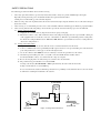
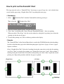
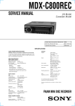
4-2 Leakage Current Hot Check
1) Plug the AC cord directly into the AC outlet. Do not use an isolation transformer for this check.
2) Connect a 1.5KΩ 10 watt resistor, paralleled by 0.15µF capacitor, between each exposed metallic parts on the unit and a
good earth ground such as a water pipe, as shown in the figure below.
3) Use an AC voltmeter, with 1000Ω/volt or more sensitivity, to measure the potential across the resistor.
4) Check all exposed metallic parts of the cover (Cable connection, Handle bracket, metallic cabinet.
Screwheads, Metallic overlays, etc), and measure the voltage at each point.
5) Reverse the AC plug in the AC outlet and repeat each of the above measurements.
6) The potential at any point should not exceed 0.75V RMS.
A leakage current tester (FLUKE MODEL : 8000A equivalent) may be used to make the hot checks.
Leakage current must not exceed 0.5 milliamp.
In case a measurement is outside of the limits specified, there is a possibility of a shock hazard, and corrective action must
be taken before returning the instrument to the customer.
AC VOLTMETER
DEVICE
UNDER
TEST
Test all
exposed
metal parts
1.5KΩ
0.15µF
Water pipe
(Earth Ground)
AC OUTLET
Figure. 1 Leakage Current Hot Check
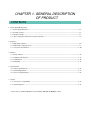
CHAPTER 1. GENERAL DESCRIPTION
OF PRODUCT
CONTENTS
1 Development Background
1-1 Development Objectives --------------------------------------------------------------------------------------------------- 1-1
1-2 Product Concept ------------------------------------------------------------------------------------------------------------- 1-1
1-3 Design Concepts ------------------------------------------------------------------------------------------------------------- 1-3
1-4 Spec. comparison between new and prior models ---------------------------------------------------------------------- 1-4
2 Features*
2-1 High Image Quality --------------------------------------------------------------------------------------------------------- 1-6
2-2 Full Features / Operation ease --------------------------------------------------------------------------------------------- 1-7
2-3 Accessories and Software -------------------------------------------------------------------------------------------------1-10
3 Exterior
3-1 Exterior Photos ------------------------------------------------------------------------------------------------------------ 1-13
3-2 6-dimensional diagram --------------------------------------------------------------------------------------------------- 1-15
3-3 Nomenclature ---------------------------------------------------------------------------------------------------------------1-16
3-4 UI Display -------------------------------------------------------------------------------------------------------------------1-17
4 Specifications
4-1 Camera Specifications -----------------------------------------------------------------------------------------------------1-21
4-2 System Requirement -------------------------------------------------------------------------------------------------------1-27
4-3 Accessory Specifications ------------------------------------------------------------------------------------------------- 1-28
5 System
5-1 Accessories’ Compatibility -----------------------------------------------------------------------------------------------1-29
5-2 System Diagram ------------------------------------------------------------------------------------------------------------1-31
* Please refer to Technical Guidance for PowerShot A20/A10 (TI-00906) P.5--P.18
1 Development Background
1-1 Development Objectives
Beginning with the ultra compact 2-megapixel 3x zoom IXY DIGITAL 300 introduced in Spring 2001, followed
in succession by the PowerShot A20/A10 and IXY DIGITAL 200, all four models adopted primary color filters
and the new image engine which provides exceptional color reproduction, and have received high acclaim for
their image quality.
Even the PowerShot A20/A10 has a friendly design intended for a wide range of users, but they are especially
suited to general use because of the high image quality and advanced functions exceptional for their class, and
support for the popular AA-size batteries, which have resulted in very good sales. The PowerShot A20/A10 is
a product for which high-volume sales can be expected, because of the positioning in the mid-price range, so
continuing to maintain a stable share in the market for this class of camera is indispensible to the business
strategy.
The PowerShot A40, with the same basic capabilities as the PowerShot A20, also incorporates advanced
photographic features provided with the PowerShot G2 and PowerShot S40/S30, and further evolves the design
so the above objectives can be achieved with a digital camera having even greater imaging capabilities for the
price. Furthermore, to target those users looking to pay a lower price, the PowerShot A30 with a 1.3-megapixelgrade CCD (active camera component pixels) will be manufactured as a successor to the PowerShot A10.
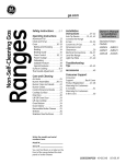
More Basic & Value
PowerShot A20/A10
+
- Movie function with Audio
- Capability of manual functions
- Upgrade for photographing features
- Suport for “new photo-printer”
PowerShot A40/A30
1-2 Product Concept
The PowerShot A40/A30 is intended as successor to the basic product concepts of the PowerShot A20/A10,
targeting the first-time digital camera user looking to simply enjoy a digital camera or to minimize expense. Our
design idea is to provide enhanced functionality through the theme of More Basics & Value, by providing “high
image quality,” “advanced features with comfortable operation” rounded out with “conservative design” and
“system accessories and software” as the product concepts.
Also, to promote a new culture of simple printing for digital camera users, the PowerShot A20/A10 supports
the so called Camera Direct {{Direct Print?}} feature that provides easy printing with the CP-10 Card Photo
Printer. The PowerShot A40/A30 will continue the same support, and also be compatible with the CP-100
Photo Printer now under development, which supports A6-size printing for credit-card to postcard size prints.
1-1
High Image Quality
- Primary color filters and signal processing algorithms to get the most of these features
- High-resolution, 1/2.7-type approx. 2 megapixel CCD (PS A40) and approx. 1.2 megapixel CCD
(PS A30)
- High-resolution retractable 3X zoom lens
R - New image capturing optics brings out high resolution (PS A40).
- Inteligent AE determines optimum exposures in all photographic situations
R - High-precision white balance (Auto + Five preset positions)
R - Wide range of ISO-equivalent speed settings (Auto/ISO 50/100/200/400 equivalent)
- Noise reduction feature for high S/N
- Equipment fot “Superfine mode” compares with RAW mode
- Totally round aperture for better background blur
Full Featurs / Operation ease
N - Color Effect Modes (Vivid color, Neutral color, Soft, Sepia and Black & White) are provided
N - Direct print function for dedicated printers (CP-10/CP-100)
R - Movie recording and playback with audio*(selectable pixel size from QVGA and Q2VGA )
*It is impossible for PS A30 to record audio
R - AF Frame (3-point) auto selection (AiAF) and center single-point selection (AF)
R - Selectable of evaluative metering and spot metering
N - “Macro”,”Snap” and ”Landscape” are available in the focus zone
N - Shutter speed is allowed from 15 sec. to 1/1500 sec.
N - Enabling for On/Off selection of AF-assist light
R - Enabling for manual settings (aperture value and shutter speed).
R - AF lock function enables fixed focus shooting
N - Built-in flash with five flashing modes
N - Magnified playback for convinient image confermation (from approx. 2X to 10X zoom)
R - Eleven-language international GUI support
R - Self-timer photography (selectable from 2sec. or 10 sec.)
N - Reset of all settings by one-touch operation
- Consentrated camera controls on the back
- Digital zoom function changes viewing angle continuously (approx. 7.5X when used in combination
with optical zoom (PS A40), approx. 6X when used in combination with optical zoom (PS A30)
- Stress free operation with 1.7 sec. interval shooting
- Built-in flash provides the range of 4.2 m shooting (wide angle), also slow-syncro-shooting
- Use of widely available size AA battery (primary:alkaline, secondary:NiCd/NiMH)
- Real-image optical zoom viewfinder
- Total of nine image quality modes (3 recording pixels X 3 compression ratio)
- Continuous shooting enables 2.5 images/sec.
- Rec.-review function (instant erase if unnessesory)
- High speed image feed on pkayback
- Selectable of video output format (NTSC/PAL)
- High-Speed Image Transfer on USB Interface
R : Equipping for the cameras launched in autumn 2001(PS G2, PS S40/S30).
N : Evolutive features compared to PS A20/A10.
1-2
Saving Design
- Power-saving and space-saving, small-package new digital signal processing IC and CPU
- Low-temperature, polysilicon 1.5-inch LCD monitor with power-saving backlight
- Space-saving, new four-blade lens cover built-in
- High-performance red-eye reduction with power-saving LED
- Power-saving design enabls approx. 1000 images to be recorded
System Accessory / Application Software
N - Tele conversion lens for taking 252 mm (35 mm film format equivalent) tele-photo angle shots
(With bayonet type new conversion lens adapter.)
- Wide Converter for taking 24.5mm (35mm format equivalent) wide-angle shots
R - Waterproof case good to 30 m underwater (renewal)
- Compact power adapter also compatible with the IXY DIGITAL 200/300 and PS A20/A10
- Nickel hydride battery and Battery charger
R Full featured application softwares
Canon Image Gateway* compliance for image upload, album creation, on-line photo printing, etc.
ZoomBrowser EX 3.2 (Win)/ImageBrowser 2.2 (Mac) featuring improved ease of operation
Photorecord 1.2 (Win) for easy layout and printing for many pictures
PhotoStitch 3.1 for creating precise panoramic pictures
RemoteCapture 2.2 for remote picture-taking through a PC
Twain Driver 4.1 / WIA Driver 4.1 (Win).
Plug-in module 4.1 / USB mounter 1.2 (Mac).
RAW Image Converter 1.2 for processing RAW images.
Apple QuickTime 5.0.
ArcSoft PhotoImpression / VideoImpression (PS A40 only).
CP-10 PrinterDriver.
* for Japanese market only
R : Equipping for the cameras launched in autumn 2001(PS G2, PS S40/S30).
N : Evolutive features compared to PS A20/A10.
1-3 Design Concepts
z Friendly, neat design to attract a wide range of users
- Simple, stylish form
- Shape fitted to the hand
z Further evolved from the PowerShot A20/A10
- Differences (grip, round mirror tube)
- Bayonet lens attachment system for easy attachment and removal
z Effective distinction of PowerShot A40/A30
- PowerShot A30: cheerful and friendly
Bright silver finish (giving a bright, soft impression)
- PowerShot A40: distinguished from competition by high-grade impression
High-grade metallic finish (gray metal with weighty impression)
1-3
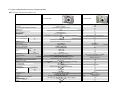
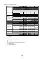
1-4 Spec. comparison between new and prior models
PowerShot A40 and PowerShot A20
PowerShot A40
CCD
Color filter
Lens(focal length 35mm film equivalent)
Optical zoom
Digital zoom
Optical viewfinder
LCD monitor
AF
Normal shooting range
W
Macro shooting range
T
Shutter
Shutter speed
Light metering method
Exposure compensation
ISO equivalent speed
W
T
Flash
macro
White balance
Shooting method
Focus
Photo effect
Continuous shooting
Movie
Recording media
Recording format
Compression
L
Recording pixels
M
(still)
S
Enlarged playback
Direct print
Interface
Battery
Dimensions (W H D)
Weight
PowerShot A20
1/2.7 type 2M (effective) , about 2.1M (total)
Primary color filter
5.4-16.2mm (35-105mm) F2.8-4.8
3X
2.5X
Real image type
1.5” low temp.p-si TFT
Selectable 3 focusing points (AiAF) or 1 (Center) ), with AF lock
76cm16-76cm
26-76cm
mechanical shutter + electoronic shutter
15-1/1500 sec
Evaluative/Spot
±2.0EV (1/3EV step)
Auto/50/100/200/400
76cm-4.2m
76cm-2.5m
26-76cm
Auto + Preset (5 positions)
Auto/Program/Manual/Stitch -assist/Movie
Macro/Snap/Landscape
Vivid/Neutral/Low sharpening/Sepia/BW
2.5 images/s
320 240 about 10 sec, 160 120 about 30 sec (with audio)
CF (Type I)
DCF (DPOF)
SuperFine/Fine/Normal L/M/S (9 pattern)
1600 1200
1024 768
640 480
about 2- 10 (scrolling possible)
supported (CP-10/CP-100)
USB/image/audio
AA alkaline 4, AA NiMH 4, Compact power adapter
110.3 71.0 37.6
250
1-4
Selectable from 3 focusing points
1-1/1500 sec
Evaluative
Auto
Auto + Preset (4 positions) , with BW
Auto/Program/Stitch -assist
Macro/Landscape
about 2.5
supported (CP-10)
USB/image
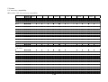
PowerShot A30 and PowerShot A10
PowerShot A30
CCD
Color filter
Lens(focal length 35mm film equivalent)
Optical zoom
Digital zoom
Optical viewfinder
LCD monitor
AF
Normal shooting range
W
Macro shooting range
T
Shutter
Shutter speed
Light metering method
Exposure compensation
ISO equivalent speed
W
T
Flash
macro
White balance
Shooting method
Focus
Photo effect
Continuous shooting
Movie
Recording media
Recording format
Compression
L
Recording pixels
M
S
Enlarged playback
Direct print
Interface
Battery
Dimensions (W H D)
Weight
PowerShot A10
1/2.7 type 1.2M (effective) , about 1.3M (total)
Primary color filter
5.4-16.2mm (35-105mm) F2.8-4.8
3X
2.5X
Real image type
1.5” low temp.p-si TFT
Selectable 3 focusing points (AiAF) or 1 (Center) ), with AF lock
76cm16-76cm
26-76cm
mechanical shutter + electoronic shutter
15-1/1500 sec
Evaluative/Spot
±2.0EV (1/3EV step)
Auto/50/100/200/400
76cm-4.2m
76cm-2.5m
26-76cm
Auto + Preset (5 positions)
Auto/Program/Manual/Stitch -assist/Movie
Macro/Snap/Landscape
Vivid/Neutral/Low sharpening/Sepia/BW
about 2.5 images/s
320 240 about 10 sec, 160 120 about 30 sec
CF (Type I)
DCF (DPOF)
SuperFine/Fine/Normal L/M/S (9 pattern)
1280 960
1024 768
640 480
about 2- 10 (scrolling possible)
supported (CP-10/CP-100)
USB/image
AA alkaline 4, AA NiMH 4, Compact power adapter
110.3 71.0 37.6
250
1-5
Selectable from 3 focusing points
1-1/1500 sec
Evaluative
Auto
Auto + Preset (4 positions) , with BW
Auto/Program/stitch -assist
Macro/landscape
about 2.5
supported (CP-10)
USB
2 Features
2-1 High Image Quality
zNew image capturing optics brings out high resolution (PS A40)
The PowerShot A40 uses the same CCD as the PowerShot A20, but with its characteristics improved by
partial modification of the image capturing optics, resulting in better resolution than the PowerShot A20.
zHigh-precision white balance (Auto + Five preset positions)
With the PowerShot A40/A30, the whole screen is divided into many blocks from which RAW calculation
data for white balance is collected, to allow precise control.
Also, as with the PowerShot G2/S40/S30, the Fluorescent Lamp preset white balance position is subdivided
into two settings, called Fluorescent Lamp and Fluorescent Lamp H, for a total of five setting positions.
Recently, fluorescent lamps have appeared with a variety of color hues, compose of many high and low color
temperature objects. The single Fluorescent Lamp white balance setting is unable to support all of these
variations. The Fluorescent Lamp position now supports relatively lower color temperatures such as “white”
and “daylight white”, and the Fluorescent Lamp H position supports relatively higher color temperatures such
as “daylight color”. The regular light bulb position is also used for incandescent-colored fluorescent bulbs.
Types of Fluorescent Light
Three-wavelength type fluorescent light designed to mimic incandescent light
Daylight white fluorescent light, white fluorescent light,
daylight white three-wavelength type fluorescent light
Daylight fluorescent light, daylight three-wavelength type fluorescent light
White Balance
Preset Position
Tungsten
Fluorescent
Fluorescent H
Table 2-1 Types of fluorescent light and white balance preset position
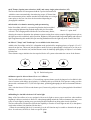
zWide range of ISO-equivalent speed settings (Auto/ISO 50/100/200/400 equivalent)
The PowerShot A40/A30 user can select ISO sensitivity equivalent to film ratings of ISO 50, 100, 200 and
400, just as one would select a file speed for a silver-halide camera according to the photographic conditions.
The low-sensitivity ISO 50 setting is best for still subjects unaffected by a slow shutter, or subjects in a bright
environment where there is no need to worry about camera shake, because of its superior noise characteristics.
On the other hand, while the ISO 400 setting has the disadvantage of lower S/N, it is appropriate for low-light
conditions where a strobe cannot (or should not) be used, or when a fast shutter speed is needed.
Taken by ISO 50 (Outdoor)
Taken by ISO 400 (Indoor / No flash)
Photo 2-1 Characteristics comparison between ISO 50 and ISO 400
1-6
2-2 Full Features / Operation ease
z Color Effect Modes (Vivid color, Neutral color, Soft, Sepia and Black & White) are provided
The PowerShot A40/A30 includes the same color modes as the PowerShot G2 and PowerShot S40/S30, plus
an additional Soft mode, providing five modes available for selection.
Also, the mode is now selected by a special-purpose (Exposure Control, WB, Color Effect, Single Image
Erase) button instead of the mode dial, so color effects can be used in ways that were impossible before,
such as in photostitching or movies. Table 2-2 shows the contents and effects.
Photo Effect
Vivid color
Neutral color
Low sharpening
Sepia
Black & White
Description
Emphasizes contrast and color intensity
Reduces contrast and color intensity
Reduces edge's emphasis
Adds sepia toning to the color information
Sets the color gain to "0," producing a black & white image
Effect
Produces a vivid and sharply-defined image
Produces a subdued, plain image
Produces a mild image
Creates an old-fashioned appearance
Produces a binary image with sharp contrast; used for text
Table 2-2 Contents and Effects of Color Effect Setting
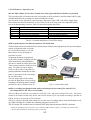
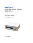
z Direct print function for dedicated printers (CP-10/CP-100)
The PowerShot A40/A30 includes the Direct Print function, which provides high quality prints by connecting the
camera via dedicated cable to Canon’s
CP-10 Card Photo Printer or CP-100
Photo Printer, newly developed for
postcard-size prints.
er
rint
oP
t
o
h
All printing operations are performed
dP
Cae
by the camera controls, including selection
CP-10
Card size
of border/borderless and adjusting the
print area to match the image aspect ratio
Ph
oto
when creating borderless credit-card-size
Pri
nte
r
prints. The print area can be aligned
relative to three sides. Credit-card-size
printing capabilities include full-size label
prints or eight copies of the same image
CP-100
on one sticker sheet.
(Operatable by battery)
The new image engine in the camera
Card size
provides the high-speed color processing
L size
Postcard size
calculations for printing that are normally
performed by driver software in the PC.
Fig. 2-1 Camera direct print
z Movie recording and playback with audio (selectable pixel size from QVGA and Q2VGA )
(It is impossible for PS A30 to record audio)
The PowerShot A30/A40 can record movies in QVGA (320 × 240 pixels) and Q2VGA (160 × 120 pixels)
formats at 20 frames/second (only the PS A40 records sound). Up to ten seconds recording is possible in
QVGA, and up to 30 seconds in Q2VGA format.
The focus, exposure, WB and zoom settings are set at the start of recording, and are used until finished recording. While recording, the available time remaining is displayed on the LCD.
The AVI-format files recorded consist of Motion JPEG image data and monaural WAVE sound data.
* When the remaining capacity of the CF is less than the buffer memory capacity, recording can continue until
the time determined by the remaining capacity of the CF.
1-7
z AF Frame (3-point) auto selection (AiAF) and center single-point selection (AF)
The PowerShot A40/A30 incorporates both the 3-point AiAF method in
which the camera automatically determines the proper AF frame from
three measurement points, and the standard AF method that uses a single
center point, so the user can select the best method depending on
photographic conditions.
z Selectable of evaluative metering and spot metering
In the PowerShot A40/A30, a spot metering function has been added
When AF frame is selected, frame turns on to green.
to the averaging light metering method employed by the PowerShot
Photo 2-2 3-point AiAF
A20/A10. The averaging method divides the screen into many blocks,
allowing the camera to determine the optimum exposure setting from various complex lighting factors such as
the light exposed in each block, subject position, brightness, background and foreground lighting and reflected
light. Supplementing this method, the spot metering method measures the light only at the center of the field.
z “Macro”,”Snap” and ”Landscape” are available in the focus zone
Added to the PowerShot A40/A30 is a Snapshot mode optimized for snapping pictures of people 1.5 to 2.5
meters from the lens. This mode joins the Macro mode for close-up photography of subjects 16 cm (26 cm in
telephoto) to 76 cm from the lens, and the Distance mode for landscape photography of subjects 5 m or further
from the lens.
These distance ranges minimize the time required for the AF system to determine the correct focal distance.
16cm
76cm
2.5m
1.5m
5m
∞
Fig. 2-2 Each focusing zone
z Shutter speed is allowed from 15 sec. to 1/1500 sec.
The PowerShot A40/A30 provides a 15-second long-exposure shutter speed, the longest level available in this
class of camera (with shutter-speed priority). Combining this speed with the F2.8 aperture setting provides
photos with a maximum of EV 1 (ISO 100 equivalent), permitting photography in dark environments without a
strobe.
Also, with the fastest 1/1500-second shutter speed, fast-moving subjects can be photographed with minimal
blurring.
z Enabling for On/Off selection of AF-assist light
Many of the PowerShot series are equipped with an assist light to ensure proper autofocus when ambient
brightness is below a certain level. However, when photographing animals in a dark environment, they may react
to the AF assist light by running away, preventing the desired photo from being taken in such situations.
The PowerShot A40/A30 therefore includes the capability to turn the AF assist light on and off, so that photos
can be taken without it in situations like the above.
*When the surrounding light level is extremely low, the AF function may be unable to determine the proper
focus. In such cases, the focus is fixed at a specific point.
1-8
z Enabling for manual settings (aperture value and shutter speed)
The PowerShot A40/A30 provides the capability for manual exposure settings, in which the user selects the
shutter speed and iris value (2 levels) as desired, so the user can completely override the camera’s automatic
controls. This capability is most suitable in cases that cannot be handled by auto exposure, such as when taking
photos under irregular lighting conditions, such as when photographing fireworks, and for intentional exposure
settings when striving to obtain special effects.
When the strobe is enabled with manual exposure settings, full luminance is provided.
z AF lock function enables fixed focus shooting
The PowerShot A40/A30 allows locking AF by pressing the AF Lock button (Macro/Snap/Distance/ /AF Lock)
when the shutter button is pressed halfway and after the AE/AF processing is finished.
Also, in previous models, the AF Lock setting was canceled after each picture was taken, but in the PowerShot
A40/A30, it remains enabled until certain operations* are performed, making possible continuous photography
with the same focus setting.
* Pressing the AF Lock button again, zooming, LCD off and changing photographic mode
z Built-in flash with five flashing modes
The strobe built into the PowerShot A40/A30 can be set to five lighting modes: auto, auto red-eye reduction, on/
off, red-eye reduction on and slow synchro, according to the photographic situation.
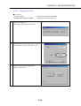
z Magnified playback for convinient image confermation (from approx. 2X to 10X zoom)
During playback, the displayed
image can be magnified with
continuous zoom from two to
ten times. Also, by pressing the
SET button when setting
magnification, the magnification
steps in three preset ratios of
2.5, 5 and 10x.
Magnified images can be
scrolled to view a desired region.
<Original>
<10X>
Photo 2-4 Magnified playback
z Eleven-language international GUI support
The LCD menu on the PowerShot A200/A100 supports
eleven languages, expanding the number of native-language
environments for the camera. The following languages are
supported.
y English
y Deutsch
y Francais
y NederLands
y Dansk
y Suomi
y Italiano
y Norsk
y Svenska
y Espanol
y
z Self-timer photography (selectable from 2sec. or 10 sec.)
The PowerShot A40/A30 adds a 2-second selection to the 10-second timer provided previously. The 2-second
setting is useful as a substitute for an external release to avoid camera shake on a tripod mount.
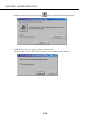
z Reset of all settings by one-touch operation
The PowerShot A40/A30 includes a function to return all user settings made on the LCD to their default values.
By pressing the menu button for five seconds, the reset dialog appears, and clicking OK executes the reset.
1-9
2-3 Accessories and Software
z Tele conversion lens for taking 252 mm (35 mm film format equivalent) tele-photo angle shots
(With bayonet type new conversion lens adapter.)
The zoom lens in the PowerShot A40/A30 performs as the equivalent of a 35- to105-mm lens in a 35-mm film
camera, but the TC-DC52 teleconversion lens has been developed to extend support for longer distance photography.
The TC-DC52 expands the lens focal distance by about 2.4x, resulting in the equivalent of a 252-mm lens in a
35-mm film camera (or up to an equivalent of 630 mm with digital zoom on the PowerShot A40, and 504 mm on
the PowerShot A30).
Teleconverters can therefore provide a photographic magnification range of over 10x using only optical magnification: from the equivalent of a 24.5-mm lens in a 35-mm film camera when using the WC-DC52 wide
converter, to the 252-mm equivalent performance with the TC-DC52 teleconverter.
To install the teleconversion lenses, the newly designed LA-DC52N conversion lens adapter is required, but
because a new bayonet attachment system is employed, attaching and removing can be done with one touch, so
operation is greatly improved.
*The optical viewfinder is not usable when a teleconverter is attached, so the LCD must be used instead. Also,
the strobe is not usable because its light is obstructed by the teleconverter.
z Waterproof case good to 30 m underwater (renewal)
The PowerShot A40/A30 fits into the specially designed WP-DC200s Waterproof Case, submersible to 30
meters for diving and snorkeling.
This waterproof case was developed based on the WP-DC200 case for the PowerShot A20/A10, so it can be
used with these models as well.
*We intend to publish information later about the special technologies used in the waterproof case.
z Full featured application softwares
Purchasers of the PowerShot S40/S30 introduced in Autumn 2001 receive various services on the Canon Image
Gateway website established by the cooperation of Canon Inc. and Canon Sales Inc. Through this service,
numerous version upgrades have been provided, starting with the ZoomBrowser EX (SCD 7.0). Also, support
for the CP-10 wass added to PhotoRecord.
This describes mainly the functions added to ZoomBrowser corresponding to the Canon Image Gateway, and
PhotoRecord support for the CP-10 (differences in the application software bundled with the PowerShot A20/
A10).
Canon Image Gateway* compliance for image upload, album creation, on-line photo printing, etc.
PowerShot A40/A30 purchasers can use the Canon Image Gateway website by registering as members, to
receive the following services :
yImage Upload Service
yImage Online Album Service
yStored Image Printing Service
(yService to transfer stored images to standby screen of cell phone) (under consideration)
yetc.
1-10
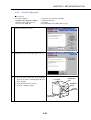
ZoomBrowser EX 3.2 (Win) and ImageBrowser 2.2 (Mac) enhanced convenience
The following functions are used with the PowerShot A40/A30.
{ Image Uploading
PowerShot A40/A30 users can store their own images on the CIG website.
yImages can be edited as a web album.
yImages can be published for users and their friends.
yPrints can be ordered from the print service.
Images are easily uploaded to CIG using ZoomBrowser EX/ImageBrowser.
yUsers can register simply using ZB/IB.
ySelected images (and sounds) can be easily uploaded.
yAutomatically download dimages set for transfer by the camera, then upload to CIG.
yFile size can be adjusted before sending, and comments can be attached.
ZoomBrowser
ImageBrowser
CIG
Fig. 2-3 Pictures upload to CIG
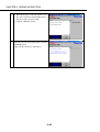
{ Auto Start function
When the camera is connected, ZB/IB can be started automatically. When started, a dialog is displayed and
the following actions can be selected:
yAutomatically download images (All, or those specified for printing or sending)
yDisplay images in the camera
yHave the camera take a picture (RemoteCapture)
When downloading is automatically selected, the following actions can be selected from a dialog when
finished:
yDisplay as slide show (if printing is specified by slide show, printing continues)
yPrint
yCreate an e-mail
yUpload images to CIG
Download
automatically
Automatic
launting
Fig. 2-3 Automatic Launch Action function
1-11
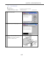
PhotoRecord 1.4 (Win) and ImageBrowser 2.2 (Mac) support for CP-10
To answer the call to print from a PC to the CP-10 with image size matched to the CP-10 standard and label
paper, this capability has been added to the previous versions: PhotoRecord 1.4 (Win) and ImageBrowser 2.1
(Mac).
Printing performance has also been improved.
{ When the Canon CP-10 is selected as the printer to use, the following three modes are selectable:
1) Layout (same as PR/IB normal layout mode)
y Layout any number of images, in any position and size.
y (PR only) Insert picture frame and background.
y Insert characters at any position and size.
y If enabled by ZB/IB, insert the date, etc.
y Prints are borderless by default. Borders can be enabled by setting margins.
2) Standard Printing (One image is printed on a CP-10 standard sheet)
y Select bordered/borderless
y Change cropped area of image
y Enter any characters
y If enabled by ZB/IB, insert the date, etc.
3) Sticker Printing (printing eight images on a CP-10 sticker sheet)
y Different images can be printed on the eight stickers, or the same image on a sheet
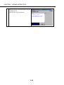
{ Other printing function enhancements
y Support for new BJ printers and borderless printing function
y Added index printing function
y (PR only) Shortened the time for images to appear after starting
Remote Capture
The following functions are added to this version since the previous version:
y Light metering system setting
y AF Frame setting
y ISO sensitivity setting
y Assist Light on/off setting
CP-10 Printer Driver prints images from a PC to the CP-10
The newly developed CP-10 Printer Driver enables printing images from a PC to the CP-10. This allows
images from Canon digital cameras prior to the PowerShot Pro90 IS to be printed on the CP-10 through the
PC.
Additionally, when combined with the bundled PhotoRecord program, print mode selection, image quality
adjustment and image trimming can be performed easily.
1-12
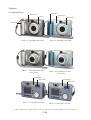
3 Exterior
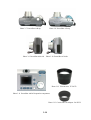
3-1 Exterior Photos
Island--blue
Graphite-gray
Bronze
Lavender-silver
Blue-pearl
Satin-silver
Photo 3-1 PowerShot A40 front
Photo 3-2 PowerShot A30 front
Photo 3-3 PowerShot A40 front
(set-up lens)
Photo 3-4 PowerShot A30 front
(set-up lens)
Graphite-gray
Gray-smoke
Graphite-gray
Gray-smoke
Photo 3-5 PowerShot A40 rear
Photo 3-6 PowerShot A30 rear
* These photos have slightly different exterior from mass-production model because of prototype.
1-13
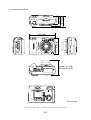
Photo 3-7 PowerShot A40 top
Photo 3-8 PowerShot A30 top
Photo 3-9 PowerShot A40 side
Photo 3-10 PowerShot A30 side
Photo 3-12 Teleconverter TC-DC52
Photo 3-11 PowerShot A40/A30 operation components
Photo 3-13 Conversion Lens Adapter LA-DC52
1-14
47.7 (1.85)
37.6 (1.48)
43.0 (1.69)
3-2 6-dimentional diagram
71.0 (2.80)
110.3 (4.342)
Tele-end :61.1 (2.40)
Wide-end:62.2 (2.45)
Unit : mm (inch)
* The size of PowerShot A30 is the same as the PowerShot A40.
1-15
3-3 Nomenclature
Shutter Button
Strap Eyelet
Red-Eye Reducation Lamp
Flash
Optical
Viewfinder
Terminal Cover
DIGITAL
Terminal
Date Battery Holder
CF Card Slot Cover
Lens/
Lens Cover
Ring removal button
DC IN
Terminal
A/V OUT Terminal
(Audio out is equiped
with the PS A40 only)
Battery Cover
Lock
Tripod Socket
Battery Cover
Viewfinder
Indicators
Button
Zoom Button
Shooting :
(Telephoto)/ (Wide Angle)
Replaying:
(Magnifying images)/
(Index Views)/
LCD Monitor
Mode Dial
Continous/
Self-Timer/
Exposure Compensation/
White Balance/
Photo Effect/ Erase Button
Button
Flash/SET Button
Macro/
Infinity/
Main Switch
Button
Snap
button
* With the PowerShot A30,the model name displayed in front changes to A30 from A40,
and the number of pixels (Lower light corner) changes to 1.2 from 2.0.
1-16
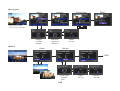
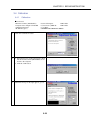
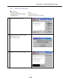
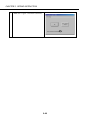
3-4 UI display
Rec. Menu
AiAF
Digital zoom
Self-timer
Review
ISO Speed
Light Merering
Resolution
Compression
AF-assist beam
File No Reset
Set up...
* In an actual display monitor,
icons do not light up simultaneously.
<Resolution>
<Compression>
y L :1280 X 960 (A 30 : 1600 X 1200)
y M :1024 X 768
y S :640 X 480
Super fine/ Fine/ Normal
<AiAF>
y On / y Off
<Light Metering>
yEvaluative/ ySpot
<AF-assist beam>
<Self-timer>
y 10 Sec/ y 20 Sec
y On / y Off
1-17
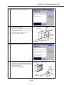
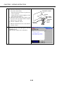
<ISO Speed>
y 50 y 100 y 200 y 400 y AUTO
<Set up...>
y Beep/ y Auto Power Down/ y Date/Time
y Format/ y Language/ y Video system
<Beep>
<Auto Power Down>
<Date/Time>
<Set up...>
y On / y Off
y On / yOff
y mm/ dd/ yy
<Format>
<Language>
<Video System>
y On / y Off
Busy.
y English
y Francais
y Dansk
y Italiano
y Svenska
1-18
y Deutsch
y NederLands
y Suomi
y Norsk
y Espanol
y NTSC/ y PAL
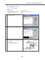
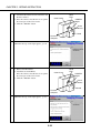
Information during shooting
Shooting Method:AUTO/Program/Manual/Stitch Assist/Movie
Exposure Compensation:±2EV 1/3 steps
White Balance mode:TTL mode/Pre-set
(Daylight/cloudy/Tungsten/Fluorescent/Fluorescen H)
ISO Sensitivilty:AUTO/50/100/200/400
Compression y Resolution:SF/F/N
Photo Effect:Effect Off/Vivid/Neutral/Low Sharpening/Sepia/ B/W
Av/Tv (At the time of manual mode)
Remaining Image Capacity
*The actual monitor display,differs.
Focus:Normal/Macro/Infinity/Snap
Drive:Single shot/Continuous shot/Self-Timer/2sec/10sec
Flash:Auto/Red-eye reducation auto/ON/OFF/Slow-sync speed
WB
<Exposure Compensation>
-2
WB
<White Balance>
+2
WB
<Photo Effect>
B/W
FluorescentH
Fluorescent
Sepia
Low Sharpening
Tungsten
Cloudy
Daylight
Neutral
Vivid
Effect Off
Auto
1-19
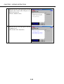
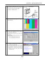
Set up print
<Style>
<Copies>
<Printing area>
PRINT
(When connected to
the CP-10 or CP-100)
<Image>
<Borders>
<Date>
yStandard
yMultiple
yBorderless
yBordered
yOn / yOff
DPOF
<Order>
<Set up>
PRINT
<Print Type>
<Date>
<File No.>
yStandard
yIndex
yOn / yOff
yOn / yOff
1-20
4 Specifications
4-1 Camera Specifications
( PowerShot A40 )
Approx. 2 million
( PowerShot A30 )
Approx. 1.2 million
-Total pixels
-Filter array
Interline
5.36 (H) X 4.05 (V) mm
(0.21 X 0.16 in.)
equivalent to 1/2.7-inch size
3.275 (H) X 3.275 (V) micron
(0.129 X 0.129 m-in.)
Approx. 2.1 million (1,688 X 1,248)
Primary color filter (Beyer)
5.28 (H) X 3.97 (V) mm
(0.21 X 0.16 in.)
equivalent to 1/2.7-inch size
4.1 (H) X 4.1 (V) micron
(0.16 X 0.16 m-in.)
Approx. 1.3 million* (1,363 X 972)
<Lens>
-Focal length
-f/number
-Lens construction
5.4 (W) - 16.2 (T) mm (35 (W) - 105 (T) mm : 35mm film equivalent)
2.8 (W) - 4.8 (T)
9 pieces in 7 groups (including 1 aspherical lens)
<Camera effective pixels>
<CCD>
-Reading format
-Image size
-Uint cell size
<Focusing range> (Measured from tip of lens)
76 cm (2.5 ft.) -infinity
-Normal
16 cm (0.53 ft.) (W) / 26 cm (0.87 ft.) (T) - 76 cm (2.5 ft.)
-Macro
*Max.shooting area Wide : 162 X 120 mm (6.4 X 4.7 in.)
Tele : 92 X 69 mm (3.6 X 2.7 in.)
1.5 m (5.0 ft.) - 2.5 m (8.3 ft.)
-Snap
5 m (17 ft.) - infinity
-Infinity
<Optical viewfinder>
-Type
-Magnification
-Coverage
Real-image optical zoom viewfinder
0.31 (W) - 0.93 (T)
Vertical : 80% Horizontal : 80%
<LCD monitor>
-Type
-Effective pixels
-Display size
-Coverage
Low-temperature polycrystalline silicon TFT color LCD
117,600 (490 (H) X 240 (V))
38 mm diagonal (1.5 inch)
100%
<Focusing>
-Control system
-Focusing points
TTL AiAF (3 focusing points) / TTL AF (1 focusing point)
(Focus lock is available.)
3 focusing points or 1 focusing point (center) (Selectable)
<Exposure control>
-Light Metering method
-Exposure method
-Exposure compensation
Evaluation (Linked with focusing point) / Spot
Program AE / Manual
+/-2.0EV (at every 1/3-stop)
1-21
<Aperture and shutter>
-Shutter type
-Shutter speed
-Aperture range
<White balance>
-Mode
<Flash (Built-in)>
-Operation modes
-Flash range
-Flash syncro. speed
-Recycling time
<Shooting specifications>
-Shooting modes
-Photo effects
-Continuous shooting modes
Mechanical shutter and electronic shutter
15 - 1/1,500 sec.
(15 - 1.3 sec. shutter is available in Manual mode.)
(Slow shutter of 1.3 sec. and more operates with noise reduction.)
W : f/2.8 - 8. 0 / T : f/4.8 - 13.4
TTL auto white balance, pre-set white balance
(Available settings : Daylight, Cloudy, Tungsten, Fluorescent or Fluorescent H )
Red-eye reduction auto, Auto, On, (Off), Red-eye reduction on, Slow-syncro.
0.76 - 4.2 m (2.5 -14 ft) (W) / 0.76 - 2.5 m (2.5 - 8.3 ft ) (T)
(When sensitivity is set to ISO100 equivalent.)
1/30 sec. or faster (Normal) / 15 sec. or faster (Slow-syncro.)
10 sec. or shorter (full flash, battery voltage = 6 V)
Auto / Program / Manual / Stitch assist / Movie
Vivid color / Neutral color / Low sharpening / Sepia / Black & White
Approx. 2.5 images/sec. (at Large / Fine mode and LCD monitor is OFF)
Number of shooting pictures
PSA40
PSA30
L/SF
5
7
L/F
7
10
L/N
14
20
M/SF M/F
9
14
10
15
M/N S/SF S/F
26
19
28
29
22
32
S/N
50
56
Operates with 2 or 10 seconds countdown. (Selectable)
Auto, ISO50, ISO100, ISO200 and ISO400
(At Auto setting, camera automatically adjusts speed in the range of
ISO50 to ISO150 equivalent.)
PS A40 : 2.5 X (Maximum of 7.5X zoom is available when combined with
-Digital zoom
optical zoom.)
PS A30 : 2 X (Maximum of 6X zoom is available when combined with
optical zoom.)
Use of “Remote Capture” software (included) when connected USB cable
-Shutter release from PC
-Camera wake-up time/Release time lag (sec.)
-Self timer
-ISO equivalent speed
Camera wake-up time Release
PS A40 | PS A30
time lag
Shooting EVF
3.6
3.6
0.08
OVF
2.5
2.5
0.05
Playback
2.1
2.1
Mode
Finder
Shooting Mode Finder
Auto
* Varies with shooting modes.
EVF
OVF
-Shooting interval (*right table)
Manual
EVF
Focus Lens
Shooting Interval (sec.)
PS A40 | PS A30
Position Position
Normal Wide
1.7
1.5
Tele
2.2
2.0
Macro Wide
1.9
1.8
Tele
2.6
2.4
Normal Wide
1.7
1.6
Tele
1.9
1.8
Macro Wide
1.8
1.7
Tele
2.2
2.1
(AF lock)
1.3
1.1
* For the actual shooting interval, the shutter speed
must ge added to the above data.
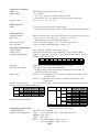
<Recording specifications>
-Compression mode
Super Fine, Fine or Normal
-Number of recording pixels
Large : 1,600 X 1,200 (PS A40) / 1,280 X 960 (PS A30)
Medium : 1,024 X 768
Small : 640 X 480
Movie : 320 X 240 (20bps) Approx. 10 sec.
160 X 120 (20bps) Approx. 30 sec.
1-22
-File format
Design rule for Camera File system (DCF (Exif 2.2))*
* “DCF” is an abbreviation of “Design rule for Camera File system” standardized
by Japan Electronic and Information Technology Industries Association (JEITA),
however a use of this abbreviation is allowed in Japan only due to trademark rights.
Exif 2.2 records shooting parameters useful for the image correction processing
performed at the time of printing.
-Recording format
-Storage media
-Storage capacity
Digital Print Order Format (DPOF) Version 1.1
Still image : JPEG
Movie
: AVI (Image data: Motion JPEG, Audio data: WAVE [monaural])
(Audio recording is available on PS A40 only.)
CompactFlash™ (CF) card (Type I)
Still (PS A40)
L / SF L / F
L / N M / SF M / F M / N S / SF S / F
File Size 957KB 611KB 302KB 450KB 294KB 155KB 208KB 141KB
FC-8M
7
11
24
16
24
46
35
50
FC-16M
15
24
48
32
49
92
70
99
FC-32M
31
49
99
67
102
189
143
206
FC-64M
64
100
200
135
205
379
288
415
FC-128M 128
200
401
271
412
760
577
831
S/N
79KB
87
172
353
707
1417
Still (PS A30)
L / SF L / F
L / N M / SF M / F M / N S / SF S / F
File Size 693KB 450KB 228KB 450KB 294KB 155KB 208KB 141KB
FC-8M
10
16
32
16
24
46
35
50
FC-16M
21
32
64
32
49
92
70
99
FC-32M
43
67
131
67
102
189
143
206
FC-64M
88
135
263
135
205
379
288
415
FC-128M 177
271
528
271
412
760
577
831
S/N
79KB
87
172
353
707
1417
Movie (PS A40/A30)
320x240
160x120
File Size 380KB/sec. 130KB/sec.
FC-8M
18sec.
48sec.
FC-16M
36sec.
97sec.
FC-32M
75sec.
198sec.
FC-64M
152sec.
399sec.
FC-128M
305sec.
799sec.
-Tone reproduction
<Playback specifications>
-Playback modes
-Direct print
-Magnify
-Vertical and horizontal
conversion
<Erasing specifications>
-Erasing modes
*Any documents to be distributed
outside the company should state that
above-written figures are measured
under Canon’s standard shooting
conditions and may vary depending
on the scene, subjects or shooting
camera settings.
Luminance signal : 8 bits
Color signal
: 8 bits (Cr / Cb)
Single, Index (9 thumbnail images), Magnification or Slide show
Image output to dedicated printer (CP-10, CP-100)
Approx. 2X to 10X on built-in LCD monitor (Zoom)
Vertical and horizontal conversion can be set on each image.
(Both LCD and Video Out play an image according to setting.)
Single image
All images
(When “All images” is set, any images in the CF card captured with another
digital camera or peripheral device (DCF format) are erased. Regarding
Canon digital cameras, images taken by PowerShot Pro70 or prior
models are not erased. Images taken by PowerShot A50 (DCF format) or
late models are erased (without EOS D2000/D6000).
However images which are protected are not erased.
1-23
<Interface>
-Computer I/F
-A/V out
<Display specifications>
-LED (Upper LED)
-LED (Lower LED)
<Power Supply>
-Power sources
-Shooting capacity
Universal Serial Bus (USB),
Video : NTSC or PAL selectable
Audio : monaural (PS A40 only)
Lights in green : Indicates that the camera is ready with flash off.
Blinks in green : Recording to CF card/Reading CF card/Erasing data on CF card
Lights in orange : Indicates that the camera and flash are ready.
Charging battery completed (adequate charge for use)
Blinks in orange : Indicates that the camera is ready (camera shake warning)
Lights in yellow : SW1 ON in macro shooting, snap shooting, infinity shooting
Blinks in yellow : Indicates that the focus goes to fixed point because the
actual focus point is not found.
Primary battery
: LR 6 / Size AA battery
Secondary battery
: (Size AA / NiCd battery), Size AA / NiMH battery
Compact power adapter : CA-PS500
LR 6 / Size AA battery (Panasonic)
LCD ON : Approx. 200 images
LCD OFF : Approx. 500 images
Size AA / NiMH battery (NB-1AH)
LCD ON : Approx. 350 images
LCD OFF : Approx. 1000 images
* Canon’s standard conditions of measuring shooting capacity are as follows:
Normal temperature (23 Celsius degrees). LCD viewfinder is ON. Shoot
images at wide angle end and at telephoto end alternately with 20 seconds
intervals. Use flash at every 4-time shootings. Turn camera off and
on at every 8-time shootings.
-Playback time
LR 6 / Size AA battery (Panasonic) : Approx. 240 min.
Size AA / NiMH battery (NB-1AH) : Approx. 240 min.
* Canon’s standard conditions of measuring playback time are as follows:
Normal temperature (23 Celsius degrees). Repeat playback automatically
at a speed of 1 image per 5 seconds.
<Camera specifications>
-Operating temperature
-Operating humidity
-Dimensions (WxHxD)
-Weight
0 - 40 C (32 - 104 F)
10 - 90%
110.3 X 71 X 37.6 mm (4.34 X 2.81 X 1.48 in.) (excluding protrusion)
Approx. 250 g (8.82 oz) (excluding batteries and CF card)
1-24
zParameter availability by modes
Auto
○
○*
ー
Flash
○
ー
ー
○
Focus zone
ー
ー
○
○*
Shooting
ー
○
Photo effect
ー
AF frame selection 3 points(AiAF)
○
1 point
ー
Exposure compensation
ー
White balance
Auto only
AF lock shooting
ー
Metering method
Evaluation
○
Spot
ー
L
○*
M
○
Recording pixels
S
○
Movie(320×240)
ー
Movie(160×120)
ー
Superfine
○
Compression level Fine
○*
Normal
○
JPEG
○
Recording format
AVI(M-JPEG/WAVE)
ー
ISO equivalent speed
Auto only
Digital zoom
○(4)
AF-assist Beam ON-OFF
○
Auto
Red-eye reduction auto
ON
OFF
Red-eye reduction ON
Slow-syncro.
Normal
Infinity
Snap
Macro
Single
Continuous
Self-timer(2/10 sec.)
Program
○
○*
○
○
ー
○
○
○
○
○
○*
○
○
○
○
○
○
○
○
○*
○
○*
○
○
ー
ー
○
○*
○
○
ー
○(2)
○(4)
○
* : Default
{ : Selectable
: Selectable for the first picture only.
— : Not selectable
: Settings are memorized after switch turns off.
(1) : Audio recording is not available with PowerShot A30
(2) : Default is ISO 50
(3) : Not selectable for ”Auto”
(4) : Default is OFF
1-25
Manual
ー
ー
○
○*
○
ー
○
○
○
○
○*
○
○
○
○
○
ー
○
○
ー
ー
○*
○
○
ー
ー
○
○*
○
○
ー
○(2)(3)
○(4)
○
Stitch
ー
ー
△
△*
ー
△
△
△
△
△
○*
ー
△
△
○
ー
△
△
ー
○
ー
△*
△
△
ー
ー
△
△*
△
○
ー
Auto only
ー
△
Movie
ー
ー
ー
ー
ー
ー
○
○
○
○
○*
ー
○
○
○
ー
○
○
ー
○
ー
ー
ー
ー
○
○
ー
ー
ー
ー
○(1)
Auto only
ー
○
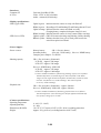
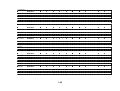
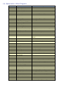
zPlayback compatibility
Playback compatibility of PowerShot/IXY DIGITAL series is as follows. PowerShot A40/A30 can accept 3200(H) X 2400(V) pixels.
PS 350
Image
PS 350
taking
PS A5/A5 Z
Cameras PS Pro70
PS A50
PS S10/S20
IXY DIGITAL
PS G1
PS Pro90 IS
EOS D30
IXY DIGITAL
200/300
PS A10/A20
PS G2
PS S30/S40
PS A30/A40
Others DCF
cameras
CIFF
CIFF
CIFF
CIFF
DCF
DCF
DCF
DCF (Still)
(Movie)
DCF
DCF (Still)
(Movie)
DCF
DCF (Still)
(Movie)
DCF (Still)
(Movie)
DCF (Still)
(Movie)
DCF (Still)
(Movie)
PS
A5/ A5 Z
*1
*2
*2
PS
Pro70
*1
*1
*1
PS A50
Playback Cameras
PS
IXY
S10/S20 DIGITAL
*1
*1
*1
*1
*3
*1
*1
*1
*1
*1
*1*3
*1
*1
*1*3
*1
*1
PS G1
Pro90 IS
*1
EOS D30
*1
IXY D
200/300
PS
A10/A20
*1
*1
*1
*5
*1
*1
*1
*5*6
*1
*5*6
*1
PS G2
*1
PS
S30/S40
PS
A40/A30
*1
*1
*5
*1
*6
*1*3
*1
*1
*5*6
*1*3
*1
*1
*5*6
*3
*4
*4
*6
*4
*4
*5
*4
*5*6
*1
*5*6
*4
*4
*4
*4
{ :Replayable
:Impossible to replay RAW images
:Thumbnail display of AVI (main image with thumbnail (.thm) only)
:Not replayable
*1 :Thumbnail display of RAW mode images
*2 :Thumbnail display of RAW mode images. JPEG file replay up to 1,024 X 768 pixels
*3 : y Only JPEGfile replay
y Replayable up to 1,632 X 1,232 pixels. With images larger than the thumbnail display (160 X 120) size the ”Image too large” message is displayed.
*4 : y Only JPEGfile replay
y Replayable up to 3,200 X 2,400 pixels. With images larger than the thumbnail display (160 X 120) size the ”Image too large” message is displayed.
*5 : y Not replayable up to definite size. “Image too large” message displayed.
*6 : y Not replayable up to definite movie shooting timesize. “Corrupted data” message displayed.
*Since the PS G2/PS G1/Pro90 IS/EOS D30’s RAW function has an internal JPEG file for playback, a full screen image is displayed.
However, if the RAW images from the PS A50 and previous models are played back with the PS G2/PS G1/Pro90 IS/EOS D30, thumbnails will be displayed.
1-26
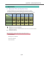
4-2 System Requirement
Windows
・Windows 98 (including SE)
・Windows 2000
・Windows Me
・Windows XP
Pentium 150MHz or better
(Windows XP: 300MHz or better)
Macintosh
・Mac OS from 8.6 to 9.2
Memory
(RAM)
・32MB or more(Win98)
・64MB or more(Win Me/2000)
・128MB or more(Win XP)
20MB or more for application
Space capacity
of hard disk
・ZoomBrowser EX 3.2 (PhotoRecord 1.4):
120MB or more
・PhotoStitch 3.1:40MB or more
・RemoteCapture 2.2:20MB or more
・Raw Image Converter 1.2:10MB or more
・USB TWAIN Driver 4.1:25MB or more
・USB WIA Driver 4.1:25MB or more
・ImageBrowser 2.2:20MB or more
・PhotoStitch 3.1:30MB or more
・RemoteCapture 2.2:15MB or more
・Raw Image Converter 1.2:10MB or more
OS
CPU
Mac OS X not supported
USB Mounter is available from Mac OS 9.0 to 9.2
Power PC
*
・CP-10 PrinterDriver:1MB or more
・Arcsoft PhotoImpression:125MB or more
・Arcsoft VideoImpression:30MB or more
Display
*1
・USB Mounter 1.2:5MB or more
・USB Plug-In Module 4.1:15MB or more
*2
・CP-10 PrinterDriver:3.8MB or more
・Arcsoft PhotoImpression:120MB or more
・Arcsoft VideoImpression:30MB or more
*1
*Capacity for installation
Available with Mac OS 9.0 or better
*2
Capacity for installton
800 x 600 dots ( 8 bits ) and over
1,024 x 768 dots ( 16 bits ) and over
(recomended)
However Arcsoft PhotoImpression and
Arcsoft VideoImpression require 800 x 600
dots (16 bits) and over
800 x 600 dots (256 color) and over
1,024 x 768 dots (32000 color) and over
(recomended)
However Arcsoft PhotoImpression and
Arcsoft VideoImpression require 800 x 600
dots (32000 colors) and over
1-27
4-3 Accessory Specifications
φ 55.65 (2.190)
φ 67.00 (2.637)
zTele-Conversion Lens TC-DC52
xMagnification : Approx. 2.4X (252 mm in 35 mm format, attached to PS A40/A30)
xLens construction : 2 elements in 2 groupes (Multicoat finishing)
xFocusing distance: Same as focusing distance of master lens
xDimensions : See Fig. 4-1
xWeight : 74 g (2.6 oz)
xThread size : 52mm dia. (Attached via Conversion lens adapter.)
23.00
(0.905)
57.00
(2.244)
Unit : mm (inch)
Fig. 4-1 Tele-Conversion Lens TC-DC52
Fig. 4-2 Conversion Lens Adapter LA-DC52B
zConversion Lens Adapter LA-DC52B
xDimensions : See Fig. 4-2
xWeight : 13 g (0.46 oz)
xAttachment method : Bayonet type
zAV Cable AVC-DC100
xPlug construction : RCA Pin-plug - L plug
xDimensions : See Fig. 4-3
1500±100
150±30
(60)
Yellow
Black•
Fig. 4-3
AV Cable AVC-DC100
zWide Converter WC-DC52
xMagnification : Approx. 0.7X (24.5 mm in 35 mm format, attached to PS A40/A30)
xLens construction : 2 elements in 2 groupes (Multicoat finishing)
xFocusing distance : Same as focusing distance of master lens
xWeight : 77 g (2.7 oz)
xThread size : 52mm dia. (Attached via Conversion lens adapter.)
1-28
Unit : mm
5 System
5-1 Accessory compatibility
zPowerShot / IXY series accessory compatibility
PS A30
PS A40
PS S30
PS S40
PS G2
IXY D 200
IXY D 300
PS A20
PS A10
IXY DIGITAL
PS Pro
90 IS
PS G1
PS S10
PS S20
PS Pro70
PS A5 Z
PS A50
PS A5
O
-
O
O
O
-
O
-
O
-
O
-
O
-
O
-
O
-
O
-
O
-
O
-
O
-
- (O) *1
O
O
-
O
O
O
-
O
O
-
O
O
-
- (O) *1
O
O
-
O
O
O
-
O
O
-
O
O
-
O
-
O
-
O
-
O
-
< Battery >
NB-5H
NB-4H
NB-1L
BP-511
BP-512
NB4-100
NB-2L
< Adapter/Charger >
CA-PS100/100E
CA-PS200
CA-PS300
CA-PS500
CA-560
CR-560
CB-2L/2LE
CB-2LS/2LSE
CB-3AH
CBK100
CB-2LT/CB-2LTE
*1 It is possible to use by inserting the adapter's DC plug in the jack of PS A40/A30/A20/A10 cameras directly without using DC coupler.
< DC coupler >
DR-100/100A
DR-200
DR-300
DR-500
DR-700
-
O
-
O
-
O
-
-
O
-
-
-
O
-
O
-
O
-
O
-
O
O
O
O
-
O
O
O
O
-
-
-
O
O
O
O
-
-
O
O
O
-
O
O
O
O
-
-
-
-
-
< Lens accessories >
WC-DC58
WC-DC52
TC-DC58
250D 58mm
500D 58mm
250D 52mm
LA-DC58
LA-DC52
LH-DC58
TC-DC52
LA-DC52B
1-29
< Speed-light >
220EX
380EX
550EX
420EX
(MR-14EX)
-
-
O
O
O
O
O
-
-
-
-
O
O
O
O
-
O
O
O
O
-
-
O
O
-
-
-
-
-
O
-
-
-
-
-
O
-
O
-
-
O
-
-
O *3
O *4
O
O
-
O
O
O
-
O
O
O
-
O
O
-
O
O
O
O
O
-
O
O
O
O
O
-
-
-
-
-
O
O
O
O
-
O
O
O
-
O
O
O
-
O
O
O
-
< Remote switch >
WL-DC100
RS-8N3
< Cable/Others >
VC-100
VC-200
AVC-DC100
AVC-DC200
IFC-100PCS
IFC-100MC
IFC-200PCS
IFC-200PCU
IFC-200MC
IFC-300PCU
AD-PC98
DIF-100
DIF-200
*3 PS A30 only
O
O
O
O
O
O
-
*4 PS A40 only
O*2
O
O
-
-
O
O
O
O
*2 PS A20 only
< Case >
SC-PS100
SC-PS300
SC-PS400
SC-PS500
SC-PS600
SC-PS700
SHC-PS200
SHC-PS300
SC-PS800
O
-
O
O
-
O
-
O
-
O
-
O
-
O
-
O
-
O
-
O
-
O
-
O
-
-
O
-
O
-
O
O
O
-
-
-
-
-
O
-
O
-
< All Weather Case/Water Proof Case >
AW-PS100
AW-PS110
AW-PS200
WP-DC100
WP-DC200
WP-DC300
WP-DC200s
O
O
-
1-30
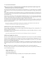
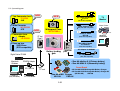
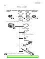
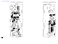
5-2 System diagram
NEW
• Tele Conversion Lens
TC-DC52
2.4X
Video Cable VC-100
NEW
• Close-up lens
250D 52mm
(EOS compatible)
Waterproof Case
WP-DC200 s
Direct I/F Cable
DIF-100
CF slot
(Type I)
(A10, A20 compatible)
Direct Printer
CF Card Reader
New
CP-100
Windows/
Machintosh
(A10, A20 compatible)
DC
Battery loading
gate
Tarminal
part
AC Adapter kit ACK600
AC Adapter CA-PS500
(A10, A20 compatible)
• Size-AA alkaline X 4 (Primary battery)
• Size-AA NiMH X 4 (Secondary battery)
PCMCIA Adapter
PC Card Slot
CP-10
Mini USB I/F Cable
IFC-300PCU
Digital
Video
Digital Printer CD-300
Parallel I/F
(Only Windows)
TV
Monitor
Only A30 (A20 compatible)
• Conversion Lens
Adapter
LA-DC52B
Macintosh
Windows
A/V cable AVC-DC100
Only A40
(IXY D 300 compatible)
CF OPEN
• Wide Converter
WC-DC52B
0.7X
NEW
Canon Brand
Type I
CF card
• 4X Size-AA NiNH Rechargeable Battery Charger
• 4X Size-AA NiNH Rechargeable Battery Charger Kit
(4X NB-1AH)
CBK100
Size-AA NiMH Charger
NB-1AH
CB3-AH
1-31
CHAPTER 2. TECHNICAL DESCRIPTION
CONTENTS
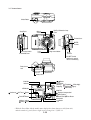
1. Functions of each unit
1.1 MAIN PCB ASS’Y --------------------------------------------------------------------------------------------------------- 2-1
1.2 DC/DC PCB ASS’Y -------------------------------------------------------------------------------------------------------- 2-1
1.3 FLASH UNIT ---------------------------------------------------------------------------------------------------------------- 2-1
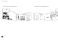
2. Outline of Circuits
2.1 Power Supply Control ------------------------------------------------------------------------------------------------------ 2-2
2.1.1 Power Supply Block Diagram ----------------------------------------------------------------------------------- 2-2
2.1.2 Power Control Sequence ------------------------------------------------------------------------------------------ 2-2
2.2 Signal Processing ------------------------------------------------------------------------------------------------------------ 2-3
2.2.1 System Control ----------------------------------------------------------------------------------------------------- 2-3
2.2.2 Picture Processing ------------------------------------------------------------------------------------------------- 2-4
2.2.3 Audio Processing (During record and playback) -------------------------------------------------------------- 2-4
3. Troubleshooting
3.1 When an Error Code is Displayed ---------------------------------------------------------------------------------------- 2-5
3.2 When a Problem Occurs ---------------------------------------------------------------------------------------------------- 2-7
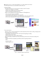
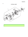
CHAPTER 2. TECHNICAL DESCRIPTION
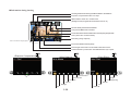
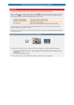
1. Functions of each unit
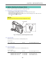
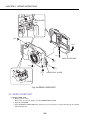
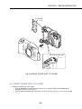
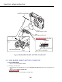
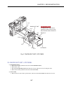
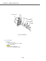
1.1 MAIN PCB ASS’Y
1)
2)
3)
4)
Driving the CCD Sensor.
Conversion of the image signal from the analog signal to the digital signal.
Controlling the power supply and the system by CPU. (Refer to Sections 2.1 and 2.2.)
Image processing, and reading and writing the image signal to and from the CF card using DSP.
(Refer to Section 2.2.2.)
5) LCD drive and amplification of the video and audio output. (A40 model only) (Refer to Section
2.2.3.)
1.2 DC/DC PCB ASS’Y
1) Power supply drive (DC/DC converter).
2) Backlight for LCD drive.
1.3 FLASH UNIT
1) Flash drive and charging circuit for the flash.
MAIN PCB ASS’Y
DC/DC PCB ASS’Y
FLASH UNIT
Fig. 1
2-1
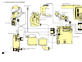
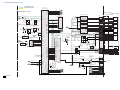
CHAPTER 2. TECHNICAL DESCRIPTION
2. Outline of Circuits
2.1 Power Supply Control
The power supply is controlled by the CPU mounted on the main PCB ass’y.
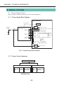
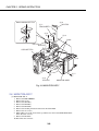
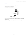
2.1.1 Power Supply Block Diagram
MAIN PCB ASS'Y
E1, E2, E3, E4
CPU
BATTERY
or
DC_IN
VBATT
REG
DC/DC
CONVERTER
VCC1L (2.5V)
VCC1 (3.3V)
E1
OUTPUT
FUSE
for System Control
VCC1A (3.3V)
E2
OUTPUT
VCC1M
(3.3V)
VDD2
(15V: A40 / 15.5V: A20 Model)
VCC2
for Image
(–7.5V: A40 / –8.0V: A20 Model) Process
(CCD etc.)
(4.2V)
VDD34
(13.5V)
VCC34
(4.2V: E3/5V: E4)
VEE2
E3 or E4
OUTPUT
for Motor Drive
for LCD, VIDEO OUT
E3: LCD
E4: Video
VCC34
(5V)
VCC1A
(3.3V)
REG
for AUDIO OUT
(A40 Model Only)
(3.3V) for RTC
Fig. 2 Power System Block Diagram
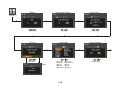
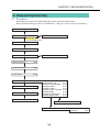
2.1.2 Power Control Sequence
Main Switch ON (E1)
Shooting Mode
Playback Mode
LCD OFF LCD ON Audio*/Video
(E2)
(E2, E3) out (E2,E4)
LCD ON Audio*/Video
(E3)
out (E4)
* A40 Model only
2-2
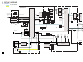
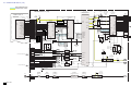
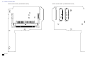
CHAPTER 2. TECHNICAL DESCRIPTION
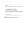
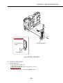
2.2 Signal Processing
MAIN PCB ASS'Y
SDRAM
CF card
HD, VD
CLK
Drive Pulse
TG
DSP
CCD
Sensor
LCD
Driver
CDS, A/D
Motor
Driver
EF LENS
Video
Amp
LCD
VIDEO OUT
AUDIO OUT
AF Support LED
FLASH MEMORY
FINDER LED
USB
Buzzer
CPU
RTC
SW
DIAL
KEY
Electric FLASH
MIC
AUDIO AMP
(A40 Model Only)
Fig. 3 Signal System Block Diagram
2.2.1 System Control
The CPU on the main PCB ass’y controls the EF lens (motor, shutter), operation switch receiver, USB
communication and flowing circuits.
•
•
•
•
•
•
•
•
TG: Creation of the CCD drive pulse
CDS, A/D: CCD signal processing and conversion of the digital data
LCD Driver: Driving the LCD
FLASH MEMORY: Firmware memory
DSP: Picture processing
RTC: Clock count for watch
AF Support LED: AF auxiliary, self-timer and red-eye protection also serves as a lamp
Electric Flash: Flash and charging circuit
2-3
CHAPTER 2. TECHNICAL DESCRIPTION
2.2.2 Picture Processing
1) The drive pulse of the CCD sensor is created by both clock from DSP and TG that is operated by
sync. signal.
The picture signal by the drive pulse is output from CCD sensor.
The output signal of the CCD picture is converted to the signal processing and the digital data by
the CDS and A/D converter, and is sent to the DSP.
2) The DSP circuit performs the following signal processing.
• Processes the picture data (using the SDRAM).
• Writes and reads the picture data to and from the CF card.
• Inputs the picture data to the CPU.
• Outputs analog video signal to the LCD and VIDEO OUT.
3) The video signal that is supplied form the DSP is controlled by the LCD driver and is displayed
on the LCD. The video amplifier is activated when the video jack is inserted to the video jack or
AV jack and drives the video signal in 75 Ω.
2.2.3 Audio Processing (During record and playback)
1) During animation recording.
• The microphone audio signal is converted to the digital data by CPU and is recorded.
2) During playback, the data is converted back to the analog audio signal and is output to the AV
jack.
Note: Installed in the A40 model only. (Audio cannot be played back by camera.)
2-4
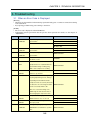
CHAPTER 2. TECHNICAL DESCRIPTION
3. Troubleshooting
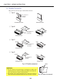
3.1 When an Error Code is Displayed
[Remedy]
• Check for any abnormalities in the mounting of probable faulty parts or connector connections referring
to the table below.
• Try replacing probable faulty parts referring to the below.
[NOTE]
• The error code is displayed on the LCD Monitor.
• Adjustments must be performed after the part has been replaced. For details, see the chapter of
“Adjustments”.
Error Code
E02
Name
Occurrence Conditions
Cause and Probable Faulty Part
AF
AF processing did not end within the
MAIN PCB ASS’Y
TIME OUT
specified time.
OPTICAL UNIT
The focus lens was not driven.
MAIN PCB ASS’Y
OPTICAL UNIT
E03
E09
E14
EF
Auto Flash Control did not end within the
MAIN PCB ASS’Y
TIME OUT
specified time.
OPTICAL UNIT
JPEG DMA
JPEG processing did not end within the
TIME OUT
specified time.
UNKOWN
When unkown error, cause of which is
MAIN PCB ASS’Y
UNKOWN
not known, occurs.
E16
IMAGING TIME
When communication between CPU and
OUT
peripheral IC is not completed within the
MAIN PCB ASS’Y
specified time during recording using
EVF or after completion of recording.
E18
E23
ZOOM LENS
Movement of the lens barrel did not end
MAIN PCB ASS’Y
ERROR
within the specified time.
OPTICAL UNIT
CF NO SPACE
When the CF becomes full during writing
of photographed images to CF, writing is
repeatedly performed with the JPEG
compression ratio successively increased
to reduce the size of the image file until it
MAIN PCB ASS’Y
can be successfully written to CF.
This error occurs when writing of the
JPEG image file fails after 10 retries at
increasingly higher compression ratios.
E24
E25
E26
POWER ON
The power of the imaging circuit on the
MAIN PCB ASS’Y
ERROR
MAIN PCB ASS’Y was not detected.
DC/DC PCB ASS’Y
FOCUS PI
Detection of the focus PI (photo-
OPTICAL UNIT
ERROR
interrupter) failed.
MAIN PCB ASS’Y
CAPTURE
Writing of the photograph image to
TIME OUT
SDRAM did not end within the specified
time.
2-5
MAIN PCB ASS’Y
CHAPTER 2. TECHNICAL DESCRIPTION
Error Code
E27
Name
Occurrence Conditions
CF WRITE
Free area could not be secured in the
TIME OVER
buffer for the photograph image within
the specified time in the continuous
Cause and Probable Faulty Part
CF CARD
MAIN PCB ASS’Y
shooting mode.
E30
POWER OFF
The camera power was turned OFF while
The battery or DC plug was removed
ERROR
the image was being recorded to the CF
while the image was being recorded to
Card. (The error code is displayed when
the CF Card.
the camera is next turned ON.)
→ Remedy: Restart the camera.
* This error may occur after E23.
E50
E51
E52
CF FORMAT
The CF Card could not be formatted
ERROR
properly.
CF ACCESS
When image data cannot be read from
ERROR
CF normally.
QUICK REVIEW
Review of the photograph image failed.
ERROR
2-6
CF CARD
CF CARD
MAIN PCB ASS’Y
CHAPTER 2. TECHNICAL DESCRIPTION
3.2 When a Problem Occurs
[Remedy]
• Check for any abnormalities in the mounting of probable faulty parts or connector connections referring
to the table below.
• Try replacing probable faulty parts referring to the table below.
[NOTE]
• Adjustments must be performed after the part has been replaced. For details, see the chapter of
“Adjustments”.
Problem (when an error code is not displayed)
Cause and Probable Faulty Part
The camera does not work.
MAIN PCB ASS’Y
REAR COVER UNIT
DC/DC PCB ASS’Y
BATTERY BOX UNIT
The image is not displayed on the LCD Monitor.
MAIN PCB ASS’Y
BUTTON PCB ASS’Y
LCD PANEL
BACK LIGHT UNIT
The photograph image is abnormal.
OPTICAL UNIT
MAIN PCB ASS’Y
The zoom does not function.
OPTICAL UNIT
MAIN PCB ASS’Y
BATTERY BOX UNIT
REAR COVER UNIT
The Built-in Flash does not fire.
FLASH UNIT
DC/DC PCB ASS’Y
Video output is strange.
MAIN PCB ASS’Y
Communications with the personal computer is not possible.
MAIN PCB ASS’Y
The CF card or Micro Drives is not recognized.
CF CARD
REAR COVER UNIT
MAIN PCB ASS’Y
Buttons/The Mode dial do not work.
REAR COVER UNIT
RLS PCB ASS’Y
2-7
CHAPTER 3. REPAIR INSTRUCTION
CONTENTS
1. Before Starting the Repair Work
1.1 Precaution on Flash High Tension Circuit ------------------------------------------------------------------------------- 3-1
1.2 List of Tools ----------------------------------------------------------------------------------------------------------------- 3-1
1.3 List of Supplies -------------------------------------------------------------------------------------------------------------- 3-1
1.4 Flexible Connectors --------------------------------------------------------------------------------------------------------- 3-2
2. Disassembly/Assembly
2.1 Procedure --------------------------------------------------------------------------------------------------------------------- 3-3
2.2 REAR COVER UNIT ------------------------------------------------------------------------------------------------------ 3-4
2.3 FRONT COVER UNIT, CF COVER ------------------------------------------------------------------------------------ 3-5
2.4 LENS BARREL SHEET, BATTERY COVER UNIT ----------------------------------------------------------------- 3-6
2.5 BACKLIGHT UNIT, LCD PANEL -------------------------------------------------------------------------------------- 3-7
2.6 MAIN PCB ASS’Y --------------------------------------------------------------------------------------------------------- 3-8
2.7 DC/DC PCB ASS’Y -------------------------------------------------------------------------------------------------------- 3-9
2.8 FLASH UNIT ---------------------------------------------------------------------------------------------------------------3-10
2.9 OPTICAL UNIT, FINDER UNIT -------------------------------------------------------------------------------------- 3-11
2.10 CCD UNIT ----------------------------------------------------------------------------------------------------------------- 3-12
2.11 BATTERY BOX UNIT, RLS PCB ASS’Y, LITHIUM BATTERY HOLDER -----------------------------------3-13
2.12 OPTICAL UNIT ---------------------------------------------------------------------------------------------------------- 3-14
2.13 Assembling the FINDER UNIT ------------------------------------------------------------------------------------------3-15
2.14 Screw List -------------------------------------------------------------------------------------------------------------------3-16
3. Adjustments
3.1 Replacement Parts and Adjustment Items ----------------------------------------------------------------------------- 3-17
3.2 Adjustment Tools ----------------------------------------------------------------------------------------------------------3-18
3.3 Before Starting Electrical Adjustments ---------------------------------------------------------------------------------3-19
3.3.1 TWAIN Driver Installation --------------------------------------------------------------------------------------3-19
3.3.2 Installing the Adjustment Software --------------------------------------------------------------------------- 3-19
3.3.3 Preparation -------------------------------------------------------------------------------------------------------- 3-21
3.3.4 Starting up the Adjustment Software ---------------------------------------------------------------------------3-22
3.3.5 Menu Window -----------------------------------------------------------------------------------------------------3-22
3.3.6 How to Use the Adjustment Software -------------------------------------------------------------------------3-22
3.4 Calibration ----------------------------------------------------------------------------------------------------------------- 3-23
3.4.1 Calibration -------------------------------------------------------------------------------------------------------- 3-23
3.5 Adjustment Procedure -----------------------------------------------------------------------------------------------------3-27
3.5.1 CCD Adjustment ------------------------------------------------------------------------------------------------- 3-27
3.5.2 Optical Unit Adjustment ---------------------------------------------------------------------------------------- 3-29
3.5.3 Imaging Process Adjustment ------------------------------------------------------------------------------------3-31
3.5.4 Pixel Dot Adjustment --------------------------------------------------------------------------------------------3-35
3.5.5 Flash Adjustment -------------------------------------------------------------------------------------------------3-37
3.5.6 Language (For Oth) -----------------------------------------------------------------------------------------------3-39
3.5.7 Language Settings ----------------------------------------------------------------------------------------------- 3-41
CHAPTER 3. REPAIR INSTRUCTION
1. Before Starting the Repair Work
Be sure to read the following precaution before starting the repair work.
1.1 Precaution on Flash High Tension Circuit
•
•
When the FRONT COVER UNIT is removed, be sure to discharge the main capacitor.
(Discharging resistor: 1 k ohms, approx. 5 W.)
First contact the GND
terminal of the main capacitor with the discharging resistor. Then contact the
positive
terminal of the main capacitor.
CAUTION:
Be careful of electric shock because the circuit is the high tension circuit.
FLASH UNIT
– terminal
+ terminal
DC/DC PCB ASS’Y
Fig. 3-1 Precaution on flash high tension circuit
1.2 List of Tools
The following tools are used for the re-assembling during service.
(1) List of tools
New
Name of tools
DRIVER HANDLE
Part No.
CY9-7014-00
Areas where supplies are used
CCD UNIT
1.3 List of Supplies
The following supplies are used for the re-assembling during service.
(1) List of supplies
New
Name of supplies
DIA BOND 1663G
ADHESIVE TAPE, SONY T4000
ADHESIVE TAPE, 3M NO.56
Part No.
CY9-8129-000
CY4-6012-000
CY4-6018-000
3-1
Areas where supplies are used
Attaching the parts together
Fixing the flexible cable
DC/DC SHIELD CASE 1
CHAPTER 3. REPAIR INSTRUCTION
1.4 Flexible Connectors
This product uses the four types of the flexible connectors.
1 Type A
The contact-piece
should face
frontwards
Unconnected state
Connected state
2 Type B
The contact-piece
UNLOCK should face
downwards
LOCK
Unlocked state
Locked state
3 Type C
UNLOCK
LOCK
The contact-piece
should face
downwards
Unlocked state
Locked state
4 Type D
UNLOCK
LOCK
The contact-piece
should face
upwards
Unlocked state
Locked state
Fig. 3-2 Flexible connectors
CAUTIONS:
1. For the connectors of Type B, Type C and Type D, set them to the
unlocked state before removing and inserting flexible card. After flexible card is inserted, set them to the locked state.
2. The flexible card is equipped with the holes as shown. Use them for
removal and insertion by inserting the tweezers into them as required.
3-2
Holes
Fig. 3-3 Holes for removal
CHAPTER 3. REPAIR INSTRUCTION
2. Disassembly/Assembly
2.1 Procedure
Disassembling procedure of PowerShot A40 (A30) is shown by the following flowchart.
Reverse the disassembling procedure to reassemble them. ∗ The pages to refer are shown in parenthesis ( ).
REAR COVER UNIT
(3-4)
FRONT COVER UNIT
(3-5)
CF COVER
(3-5)
LCD PANEL
(3-7)
CAUTION
Be careful high tension
LENS BARREL SHEET
(3-6)
BATTERY COVER UNIT
(3-6)
BACK LIGHT UNIT
(3-7)
MAIN PCB ASS’Y
(3-8)
DC/DC PCB ASS’Y
(3-9)
FLASH UNIT
(3-10)
OPTICAL UNIT
(3-11)
BATTERY BOX UNIT
(3-13)
RLS PCB ASS’Y
(3-13)
LENS PLATE
LENS BARREL CAP
BARRIER CLOSE SPRING
BARRIER PLATE 1
BARRIER PLATE 2
BARRIER PLATE 2 SPRING
BARRIER BASE
BARRIER OPEN SPRING
BARRIER DRIVE RING
(3-14)
(3-14)
(3-14)
(3-14)
(3-14)
(3-14)
(3-14)
(3-14)
(3-14)
LITIUM BATTERY HOLDER (3-13)
FINDER UNIT
CCD UNIT
3-3
(3-12)
(3-11)
CCD RUBBER
IR FILTER
(3-12)
(3-12)
CHAPTER 3. REPAIR INSTRUCTION
REAR COVER
UNIT
(1)-3
(1)-1
a
(1)-3
(1)-1
b
REAR COVER UNIT
a
(1)-1
(1)-1
a
b
(1)-1
(1)-1
b
CONNECTOR COVER
(1)-2 CF COVER
Fig. 3-4 REAR COVER UNIT
2.2 REAR COVER UNIT
(1) REAR COVER UNIT
1. Remove the six screws.
Remove the one screw by turning over the CONNECTOR COVER.
2. Open the CF COVER.
3. Open the REAR COVER UNIT in the direction of arrow and remove it by disconnecting the two flexible
printed wired board.
3-4
CHAPTER 3. REPAIR INSTRUCTION
CF COVER
(1)-2
(1)-2
BATTERY COVER UNIT
(1)-1
Fig. 3-5 FRONT COVER UNIT, CF COVER
2.3 FRONT COVER UNIT, CF COVER
(1) FRONT COVER UNIT, CF COVER
1. Open the BATTERY COVER UNIT after releasing the look while pushing the BATTERY OPEN
BUTTON in the direction of the arrow .
2. Take the FRONT COVER UNIT in the direction of arrow and at the same time remove the CF COVER.
3-5
CHAPTER 3. REPAIR INSTRUCTION
BATTERY COVER BAR
(1)-1
LENS BARREL SHEET
(2)-2
BATTERY COVER UNIT
(2)-1
NOTE (Assembling) (Top view)
Lever block
BATTERY COVER
BAR
BATTERY COVER UNIT
BATTERY COVER UNIT Groove
BATTERY COVER BAR
Fig. 3-6 LENS BARREL SHEET, BATTERY COVER UNIT
2.4 LENS BARREL SHEET, BATTERY COVER UNIT
(1) LENS BARREL SHEET
1. Remove the LENS BARREL SHEET.
(2) BATTERY COVER UNIT
1. Insert tweezers or the like into the groove of the BATTERY COVER BAR and remove it in the direction of
arrow.
2. Remove the BATTERY COVER UNIT.
NOTE (Assembling)
Attach the lever block to the BATTERY COVER UNIT.
3-6
CHAPTER 3. REPAIR INSTRUCTION
(1)-4
BACKLIGHT UNIT
NOTE (Assembling)
(1)-3
(1)-2
c
The BACKLIGHT UNIT that is
supplied as the service part has
the protection sheet on the back.
Remove it.
(2)-1
Claws
Claws
(2)-1
(1)-1
(1)-3
Claws
(2)-1
LCD PANEL
Fig. 3-7 BACKLIGHT UNIT, LCD PANEL
2.5 BACKLIGHT UNIT, LCD PANEL
(1) BACKLIGHT UNIT
1. Remove the flexible printed wired board of the BACKLIGHT UNIT.
2. Remove the screw.
3. Rotate the BACKLIGHT UNIT in the direction of arrow and remove it by releasing the claws.
4. Remove the flexible printed wired board of the LCD PANEL.
(2) LCD PANEL
1. Release the four claws in the top and bottom, and remove the LCD PANEL in the direction of arrow.
3-7
CHAPTER 3. REPAIR INSTRUCTION
How to fold the OPT FPC
(1)-4
M-R FPC
(1)-1
EMC SHEET 2
(1)-2
d
(1)-3
Claws
OPT FPC
M-S FPC
CCD UNIT FPC
(1)-9
(1)-8
(1)-10
(1)-6
(1)-7
c
(1)-5
M-D FPC
MAIN PCB ASS’Y
Fig. 3-8 MAIN PCB ASS’Y
2.6 MAIN PCB ASS’Y
(1) MAIN PCB ASS’Y
1. Remove the EMC SHEET 2.
2. Remove the screws.
3. Remove the OPT FPC.
4. Remove the M-R FPC.
5. Remove the M-D FPC.
6. Remove the flexible printed wired board of the CCD UNIT.
7. Remove the two screws.
8. While taking care of the claws in the top and bottom, remove the MAIN PCB ASS'Y
in the direction of arrow.
9. Remove the M-S FPC.
10. Disconnect the connector.
3-8
CHAPTER 3. REPAIR INSTRUCTION
(1)-1
(1)-3
(1)-1
(1)-2
NOTE (Assembling)
c
DC/DC PCB ASS’Y
DC/DC SHIELD
CASE 1
Insulation tape
Fig. 3-9 DC/DC PCB ASS’Y
2.7 DC/DC PCB ASS’Y
(1) DC/DC PCB ASS’Y
1. Disconnect the two connectors.
2. Remove the two screws.
3. Remove the DC/DC PCB ASS’Y in the direction of arrow.
NOTE (Assembling)
Attach the insulation tape to the DC/DC SHIELD CASE 1.
3-9
CHAPTER 3. REPAIR INSTRUCTION
(1)-6
M-S FPC
(1)-2
Mold part
FLASH UNIT
(1)-5
EMS SHEET 1
c
(1)-3
c
(1)-3
(1)-4
Fig. 3-10 FLASH UNIT
2.8 FLASH UNIT
(1) FLASH UNIT
1. Remove the HIGH VOLTAGE CAUTION TAPE.
2. Remove the mold part of the FLASH UNIT from the dowel with the sharp point tweezers or the like.
3. Remove the two screws. (One screw from the front and the other from the rear.)
4. Remove the FLASH UNIT by sliding it.
5. Remove the EMS SHEET 1.
6. Remove the M-S FPC.
3-10
CHAPTER 3. REPAIR INSTRUCTION
FINDER UNIT
OPTICAL UNIT
e (2)-2
(2)-1
(2)-3
(1)-2
e
(1)-1
Fig. 3-11 OPTICAL UNIT, FINDER UNIT
2.9 OPTICAL UNIT, FINDER UNIT
(1) OPTICAL UNIT
1. Remove the four screws.
2. While taking care of flexible printed wired board, remove the OPTICAL UNIT in the direction of arrow.
(2) FINDER UNIT
1. Remove the flexible printed wired board.
2. Remove the two screws.
3. Remove the FINDER UNIT in the direction of arrow.
3-11
CHAPTER 3. REPAIR INSTRUCTION
OPTICAL UNIT
(1)-3
IR FILTER
(1)-3
CCD RUBBER
(1)-2
CCD WASHER
CCD UNIT
(1)-2
f
(1)-1
Fig. 3-12 CCD UNIT
2.10 CCD UNIT
(1) CCD UNIT
1. Remove the three screws.
∗ Use the HAND DRILL BIT (CY9-1548-000).
2. Remove the CCD UNIT.
CAUTION
Be careful not to drop the washers.
3. Remove the CCD RUBBER, IR FILTER.
3-12
CHAPTER 3. REPAIR INSTRUCTION
(2)-1
RLS PCB ASS’Y
Remove soldering
(3)-1
LITHIUM BATTERY
Claw
(2)-2
(3)-1
LITHIUM BATTERY HOLDER
(1)-2
(1)-1
e
BATTERY BOX UNIT
MAIN FRAME
Fig. 3-13 BATTERY BOX UNIT, RLS PCB ASS’Y, LITHIUM BATTERY HOLDER
2.11 BATTERY BOX UNIT, RLS PCB ASS’Y,
LITHIUM BATTERY HOLDER
(1) BATTERY BOX UNIT
1. Remove the two screws.
2. Remove the BATTERY BOX UNIT in the direction of arrow.
(2) RLS PCB ASS’Y
1. Remove soldering. (
: red, : black)
2. Release the claws and remove the RLS PCB ASS’Y in the direction of arrow.
(3) LITHIUM BATTERY HOLDER
1. Remove the LITHIUM BATTERY from the LITHIUM BATTERY HOLDER.
3-13
CHAPTER 3. REPAIR INSTRUCTION
Insert tweezers
or the like. (1)-2
Insert tweezers
or the like. (1)-1
NOTE (Assembling) (1)-3 to (1)-7
LENS PLATE
LENS BARREL
CAP
(1)-3
BARRIER PLATE 2 SPRING
BARRIER PLATE 2
BARRIER CLOSE
BARRIER PLATE 1
SPRING
(1)-5
(1)-3
(1)-4
(1)-5
BARRIER
CLOSE
SPRING
g (1)-6
(1)-7
(1)-6
(1)-4
(1)-8
(1)-7
(1)-9
BARRIER BASE
BARRIER DRIVE
RING (1)-11
BARRIER
OPEN
SPRING
(1)-10
BARRIER PLATE 1
BARRIER PLATE 2
NOTE (Assembling)
(1)-10
(1)-8
BARRIER
OPEN
SPRING
(1)-10
DC2.5V
2.12 OPTICAL UNIT
BARRIER PLATE 2
SPRING
DC2.5V
Fig. 3-14 OPTICAL UNIT
(1) OPTICAL UNIT
1. Remove the LENS PLATE by inserting tweezers or the like into its groove.
2. Insert tweezers or the like to the LENS BARREL CAP. Rotate it in the clockwise direction and remove it.
3. Remove the BARRIER CLOSE SPRING (2 pieces).
4. Remove an end of the BARRIER PLATE 2 SPIRNG (2 pieces) and loosen the fastening of the BARRIER
PLATE 2.
5. Remove the BARRIER PLATE 1 (2 pieces).
6. Remove the BARRIER PLATE 2 (2 pieces).
7. Remove the BARRIER PLATE 2 SPIRNG (2 pieces).
8. Remove the two screws.
NOTE (Assembling) Apply the voltage (DC 2.5V) across the motor terminal to drive the motor until the
motor stops and the BARREL is fully comes out.
9. Remove the BARRIER BASE.
10. Remove the BARRIER OPEN SPRING (2 pieces).
NOTE (Assembling) Apply the voltage (DC 2.5V) across the motor terminal to drive the motor until the
motor stops and the BARREL is full housed.
11. Remove the BARRIER DRIVE RING.
3-14
CHAPTER 3. REPAIR INSTRUCTION
(1)-1
BARREL
DC2.5V
(1)-1
The SLIDER must have been moved
fully to the top of the BARREL.
(1)-2
SLIDER
FINDER UNIT
(1)-2
e
(1)-3
BARREL
FINDER UNIT
DC2.5V
(1)-3
Fig. 3-15 Assembling the FINDER UNIT
2.13 Assembling the FINDER UNIT
(1) Assembling the FINDER UNIT
1. Apply the voltage (DC 2.5V) across the motor terminal to drive the motor until the motor stops and the
BARREL fully comes out.
2. Move the SLIDER fully to the top of the BARREL and secure it with the two screws.
3. Apply the voltage (DC 2.5V) across the motor terminal to drive the motor until the motor stops and the
BARREL is full housed.
3-15
CHAPTER 3. REPAIR INSTRUCTION
2.14 Screw List
a A40
CD1-4276-000
a A30
CD1-4283-000
5.0mm
GRAY/SILVER
M1.7
(SELF TAP)
b A30
GRAY/SILVER
M1.7
GRAY/SILVER
M1.7
c
d
e
CD1-3441-000
XA4-9170-407
3.0mm
3.0mm
METAL
M1.7
f
g
XA4-9170-307
XA4-9140-359
3.0mm
METAL
M1.4
(SELF TAP)
3.5mm
CD1-4270-000
3.5mm
GRAY
M1.7
b A30
CD1-4284-000
3.5mm
5.0mm
GRAY/SILVER
M1.7
(SELF TAP)
CD1-4277-000
b A40
CD1-4277-000
BLACK
M1.7
(SELF TAP)
3.5mm
METAL
M1.4
(SELF TAP)
3-16
4.0mm
METAL
M1.4
(SELF TAP)
CHAPTER 3. REPAIR INSTRUCTION
3. Adjustments
3.1 Replacement Parts and Adjustment Items
PowerShot A30/A40 requires electrical adjustments when certain parts are replaced.
The table below indicates the adjustments required for the respective part replacements.
For all other parts not listed below, no electrical adjustments are necessary after replacement.
Adjustment Items
CCD
Adjustment
Optical Unit
Adjustment
Replacement Part
Imaging
Process
Pixel Dot
Flash
Adjustment
Adjustment
Adjustment
BATTERY BOX UNIT
DC/DC PCB ASS’Y
CCD UNIT
#1
#2
#3
#4
OPTICAL UNIT
FLASH UNIT
MAIN PCB ASS’Y
LCD PANEL
BACK LIGHT UNIT
: Adjustment is necessary after replacement.
: Adjustment is necessary after replacement.
(Adjustment is not necessary, only if the adjustment data has been saved and then transferred
after the part is replaced.)
Blank : Adjustment is unnecessary.
∗ When CCD UNIT is replaced, adjust certainly at the procedure as below.
#1. CCD Adjustment
#2. Imaging Process Adjustment
#3. Pixel Dot Adjustment
#4. Flash Adjustment
3-17
CHAPTER 3. REPAIR INSTRUCTION
3.2 Adjustment Tools
The following tools are required for electrical adjustment.
DESCRIPTION
PARTS NO.
PC/AT-Compatible Machine
(Windows98 pre-installed Model, USB port)
Adjustment Software (CD-ROM)
—
CY8-4375-031
REMARKS
Local purchase
CD-ROM,
SERVICE MANUAL (J/E)
Compact Power Adapter CA-PS500
—
Enclosed in camera kit
(or Local purchase)
INTERFACE CABLE IFC-300PCU (USB Cable)
—
(or Local purchase)
Brightness Box (light source A)
—
Local purchase
Color Viewer (5600° K)
DY9-2039-100
(or Local purchase)
Standard Color Bar Chart
DY9-2002-000
(or Local purchase)
Standard 18% Gray Chart
CY4-6016-000
CHART, 18%GRAY
Zoom /AF Chart
W-10 Filter
C-12 Filter
*2
—
*1
CY9-1543-000
(or Local purchase)
DY9-2029-000
(or Local purchase)
ND-4 Filter
—
Local purchase
ND-8 Filter
—
Local purchase
Light-Shielding Cloth (500 × 500 or larger)
—
Local purchase
Tripod
—
Local purchase
*1
Print the Auto Focus Chart on the legal size paper from the “Zoom_AFChart_Legal.pdf ” ( in the folder
of this CD-ROM, :\Adjust\Chart).
Print the Auto Focus Chart on the A3 size paper from the “Zoom_AFChart_A3.pdf ”.
*2
2pcs. required.
3-18
CHAPTER 3. REPAIR INSTRUCTION
3.3 Before Starting Electrical Adjustments
3.3.1
TWAIN Driver Installation
Install the USB Driver for Adjustment in the CD-ROM to PC.
(“This Adjustment Software” is impossible when the RS-232C TWAIN driver is used.)
3.3.2
Installing the Adjustment Software
1. Double click the icon on the launcher screen or a file in the CD-ROM. (Model name of the camera
that you are going to adjust and the name of the adjustment software are different.)
A40
Camera Type
Third place
Destination
of Serial No.
USA/Europe/Canada
2/3/5
OTH (Asia/Oceania)
4
Adjustment Software
Icon
File Path
A40_USA_Adj.
A40_OTH_Adj.
\Adjust\A40\USA\Setup.exe
\Adjust\A40\OTH\Setup.exe
A30
Camera Type
Third place
Destination
of Serial No.
USA/Europe/Canada
2/3/5
OTH (Asia/Oceania)
4
Adjustment Software
Icon
A30_USA_Adj.
A30_OTH_Adj.
File Path
\Adjust\A30\USA\Setup.exe
\Adjust\A30\OTH\Setup.exe
2. When the dialog box below appears, click the “OK” button.
* All figures for the
Adjustment Software
are examples of the
PowerShot A40.
3-19
CHAPTER 3. REPAIR INSTRUCTION
3. When the dialog box below appears, click the
button. (Software installation will then begin.)
4. When the dialog box below appears, click the “Continue” button.
(In the case that you do not add a shortcut on desktop, remove clicking from the check box.)
3-20
CHAPTER 3. REPAIR INSTRUCTION
3.3.3
Preparation
Before starting up the Adjustment Software, follow the preparatory steps below:
1. Obtain all the tools necessary for the adjustment.
2. Connect the Camera to the Power Source with the Compact Power Adapter CA-PS500.
3. Set the Replay Mode on the camera and turn on.
Personal Computer
USB
INTERFACE CABLE
IFC-300PCU
CAMERA BODY
DIGITAL
Compact Power Adapter
CA-PS500
4. Connect the Camera’s Digital terminal to the PC’s USB Port with INTERFACE CABLE IFC-300
PCU.
5. Turn on the camera.
Note: Perform the preparation in the following order otherwise the camera won’t work properly.
3-21
CHAPTER 3. REPAIR INSTRUCTION
3.3.4
Starting up the Adjustment Software
After completing the preparatory steps, click Start and move the cursor to Program; then select Canon
Digital Camera and click PowerShot A30/A40 Adjustment.
3.3.5
Menu Window
When the Adjustment Software starts up, the Menu Window below will appear.
3.3.6
How to Use the Adjustment Software
Calibration/Adjustment
For starting, click the button related with adjustment.
* Whenever you use your light source for the adjustment for the first time, be sure to click the “Calibration” Button.
Quitting the Adjustment Software
Click the “Exit” button.
Saving or Loading data
• “Save” button : This button saves all adjustment data stored on the camera in text format.
• “Load” button : This button loads all adjustment data saved in text format to the camera.
Saving or Loading data
• “Save” button : This button saves all adjustment data stored on the camera in text format.
• “Load” button : This button loads all adjustment data saved in text format to the camera.
Notes
• If the adjustment fails, a message indicating the failure will appear on each product. If this happens,
do the adjustment again.
• The Adjustment Software is dedicated only to Canon Digital Camera PowerShot A30/A40.
Never use it for any other camera.
• The Windows98/2000 must be pre-installed on the computer that is equipped with the USB terminal. (Windows95 does not support the USB.)
* The operation with the WinMe, etc. is not guaranteed.
3-22
CHAPTER 3. REPAIR INSTRUCTION
3.4 Calibration
3.4.1
Calibration
■ Tools Used
• Reference Camera (Merchandise)
• Compact Power Adapter CA-PS500
• Adjustment Software
• W-10 Filter (2pcs.)
• Personal Computer
• ND-8 Filter
• Color Viewer (5600° K)
• ND-4 Filter
• C-12 Filter
• INTERFACE CABLE IFC-300PCU
1
Click the “Calibration” button.
2
1. When the message on the right appears, check
that the reference camera (Merchandise) is connected to the computer.
2. Click the “OK” button.
3
When the message on the right appears, go to 4.
3-23
CHAPTER 3. REPAIR INSTRUCTION
4
1. Place the camera so that lens is set against the
light source surface of the Brightness Box via
the C-12 Filter.
2. Set the Brightness Box to EV12.
3. Click the “Check” button.
4. Check the Brightness level if it is within
0 ± 5.
* If not, calibrate the Brightness Box until it
becomes within 0 ± 5.
5. Click the “NEXT” button.
5
1. When the message on the right appears, Set the
Brightness Box to EV15 and attach the ND-8
Filter while setting the C-12 Filter between the
lens.
2. Click the “Check” button.
3. Check the Brightness level if it is within
0 ± 5.
* If not, calibrate the Brightness Box until it
becomes within 0 ± 5.
4. Click the “NEXT” button.
6
When the message on the right appears go to 7.
7
1. Attach the ND-4 Filters between the Lens and
the Color Viewer.
2. Place the camera so that the lens is set against
the center part of the Color Viewer.
3. Click the “ADJUST” button.
Brightness
Box
C-12 Filter
CAMERA
BODY
Power
Source
Personal
Computer
Color Viewer
ND-4
Filter
CAMERA
BODY
Power
Source
Stand
Personal
Computer
3-24
CHAPTER 3. REPAIR INSTRUCTION
8
When the message on the right appears go to 9.
9
1. Remove the ND-4 Filter.
2. Attach the two W-10 Filters between the Lens
and the Color Viewer.
Place the camera so that the lens is set against
the center part of the Color Viewer.
3. Click the “ADJUST” button.
Color Viewer
W-10
Filter
CAMERA
BODY
Power
Source
Stand
Personal
Computer
10
When the message on the right appears go to 11.
11
1. Attach the Color Bar Chart to the Color Viewer.
2. Place the camera so that the Viewing image of
the color bar chart is the full of LCD with the
ND-4 Filter attached.
3. Click the “ADJUST” button.
Color Viewer
Color Bar Chart
ND-4
Filter
CAMERA
BODY
Power
Source
Personal
Computer
3-25
Stand
CHAPTER 3. REPAIR INSTRUCTION
12
Point and drag the shot yellow area to be measured with mouse.
13
Check “Save as Reference Yellow (or Red)”
click the “OK” button.
Measure “RED” referring to the procedures from
the above.
14
When the message on the right appears, click the
“FINISH” button.
(This ends the “Calibration”.)
3-26
CHAPTER 3. REPAIR INSTRUCTION
3.5 Adjustment Procedure
3.5.1
CCD Adjustment
■ Tools Used
• Personal Computer
• INTERFACE CABLE IFC-300PCU
• Brightness Box (light source A)
• Adjustment Software
• Compact Power Adapter CA-PS500
• C-12 Filter
1
Click the “CCD” button.
2
When the message on the right appears, go to 3.
3
1. Place the camera so that lens is set against the
light source surface of the Brightness Box via
the C-12 Filter.
2. Set the Brightness Box to EV12.
3. Click the “ADJUST” button.
C-12 Filter
Brightness
Box
CAMERA
BODY
Power
Source
Personal
Computer
3-27
CHAPTER 3. REPAIR INSTRUCTION
4
When the message on the right appears, Set the
Brightness Box to EV15 while setting the C-12
Filter between the lens.
Click the “ADJUST” button.
5
When the message on the right appears, click the
“FINISH” button.
(This ends the “CCD” Adjustment.)
3-28
CHAPTER 3. REPAIR INSTRUCTION
3.5.2
Optical Unit Adjustment
■ Tools Used
• Personal Computer
• INTERFACE CABLE IFC-300PCU
• ZOOM/AF Chart
• Tripod
• Adjustment Software
• Compact Power Adapter CA-PS500
1
Click the “Optical Unit” button.
2
When the message on the right appears,
turn off/on the camera.
Click the “OK” button.
3
When the message on the right appears, go to 4.
3-29
CHAPTER 3. REPAIR INSTRUCTION
4
1. Place the Zoom Chart at 53.5cm away from the
front of the camera finder.
* Place the Auto Focus Chart on a plain color
wall or equivalent.
* Adjust the light so that the brightness of the
chart will be about EV8.5.
2. Adjust the position of the camera finely so that
the center of the Auto Focus Chart is aligned
with the center of the LCD.
3. Click the “ADJUST” button.
* When the adjustment does not work, click the
“Default” button.
5
ZOOM/AF CHART
53.5cm
Power
Source
Personal
Computer
When the message on the right appears, click the
“FINISH” button.
(This ends the “Optical Unit” Adjustment.)
3-30
CAMERA
BODY
Tripod
CHAPTER 3. REPAIR INSTRUCTION
3.5.3
Imaging Process Adjustment
■ Tools Used
• Personal Computer
• INTERFACE CABLE IFC-300PCU
• Brightness Box (light source A)
• Compact Power Adapter CA-PS700
• Color Viewer (5600° K)
• Adjustment Software
• W-10 Filter (2 pcs.)
• Light-Shielding Cloth
1
Click the “Imaging Process” button.
2
When the message on the right appears,
turn off/on the camera.
Click the “OK” button.
3
When the message on the right appears, go to 4.
3-31
• DC Coupler DR-700
• Color Bar Chart
• ND-4 Filter
CHAPTER 3. REPAIR INSTRUCTION
4
1. Attach the ND-4 Filters between the Lens and
the Color Viewer.
2. Place the camera so that the lens is set against
the center part of the Color Viewer.
3. Click the “ADJUST” button.
Color Viewer
ND-4
Filter
CAMERA
BODY
Power
Source
Stand
Personal
Computer
5
When the message on the right appears, go to 6.
6
1. Remove the ND-4 Filter.
2. Attach the two W-10 Filters.
Place the camera so that the lens is set against
the center part of the Color Viewer.
3. Click the “ADJUST” button.
Color Viewer
W-10
Filter
CAMERA
BODY
Power
Source
Stand
Personal
Computer
7
When the message on the right appears, go to 8.
3-32
CHAPTER 3. REPAIR INSTRUCTION
8
1. Attach the Color Bar Chart to the Color Viewer.
2. Place the camera so that the viewing image of
the color bar chart is the full of LCD.
3. Click the “ADJUST” button.
Color Viewer
Color Bar Chart
ND-4
Filter
CAMERA
BODY
Power
Source
Personal
Computer
9
Point and drag the shot yellow area to be measured with mouse.
10
1. Check “Save as Reference Yellow (or Red)”,
and click the “OK” button.
* Measure “Red” referring to the procedures from
the above.
2. If these data are within specifications, go to 12.
* Specification
Ave_Cr = Reference Camera ± 10
Ave_Cb = Reference Camera ± 10
11
1. Confirm to see that the image on the PC monitor satisfies the specifications.
2. If the image on the PC monitor does not satisfy
the specifications, change the data using UP,
DOWN button or change the data directly by
typing the data in the text box. Then click the
“UPDATE” button.
3-33
Stand
CHAPTER 3. REPAIR INSTRUCTION
12
When the adjustment is completed, click the
“FINISH” button.
(This ends the “Imaging Process” Adjustment.)
3-34
CHAPTER 3. REPAIR INSTRUCTION
3.5.4
Pixel Dot Adjustment
■ Tools Used
• Personal Computer
• INTERFACE CABLE IFC-300PCU
• Brightness Box (light source A)
• Color Viewer (5600° K)
• Compact Power Adapter CA-PS500
• Adjustment Software
• C-12 Filter
• Light-Shielding Cloth (500 × 500 or larger)
1
Click the “Pixel Dot” button.
2
When the message on the right appears, go to 3.
3
1. Place the camera so that lens is set against the
light source surface of the Brightness Box via
the C-12 Filter.
2. Set the Brightness Box to EV12.
3. Click the “ADJUST” button.
C-12 Filter
Brightness
Box
CAMERA
BODY
Power
Source
Personal
Computer
3-35
CHAPTER 3. REPAIR INSTRUCTION
4
1. When the message on the right appears, cover
the camera with the Light-Shielding Cloth so
that the no light reasons the CCD.
2. Click the “ADJUST” button.
5
When the message on the right appears, click the
“FINISH” button.
(This ends the “Pixel Dot” Adjustment.)
3-36
CHAPTER 3. REPAIR INSTRUCTION
3.5.5
Flash Adjustment
■ Tools Used
• Personal Computer
• INTERFACE CABLE IFC-300PCU
• Compact Power Adapter CA-PS500
• Adjustment Software
1
Click the “Flash” button.
2
When the message on the right appears, go to 3.
3
1. Set 18% Gray Chart 60cm from the Finder
front.
2. Make the room as dark as a darkroom.
3. Click the “ADJUST” button.
• 18% Gray Chart
18% Gray Chart
60cm
Power
Source
CAMERA
BODY
Personal
Computer
3-37
Tripod
CHAPTER 3. REPAIR INSTRUCTION
4
When the message on the right appears, click the
“FINISH” button.
(This ends the “Flash” Adjustment.)
3-38
CHAPTER 3. REPAIR INSTRUCTION
3.5.6
Language (For Oth)
■ Tools Used
• Personal Computer
• INTERFACE CABLE IFC-300PCU
• Compact Power Adapter CA-PS500
• Adjustment Software (FontSet.exe)
1
Open the “FontSet.exe”
and click the “New Connection” button.
2
When the message on the right appears, confirm
the model name, and click the “OK” button.
3
When the message on the right appears,
click the “Oth” button.
3-39
CHAPTER 3. REPAIR INSTRUCTION
4
*Make sure to appear “err:0 on the bottom line.
3-40
CHAPTER 3. REPAIR INSTRUCTION
3.5.7
Language Settings
It is not required to set the language.
3-41
CHAPTER 4. PARTS CATALOG
CONTENTS
PowerShot A40/PowerShot A30
Casing Parts ----------------------------------------------------------------------------------------------------------------------Internal Parts-1 ------------------------------------------------------------------------------------------------------------------Internal Parts-2 ------------------------------------------------------------------------------------------------------------------OPTICAL UNIT -----------------------------------------------------------------------------------------------------------------
Pg1
Pg2
Pg3
Pg4
Accessories-1 ------------------------------------------------------------------------------------------------------------------------- Pg5
Accessories-2 ------------------------------------------------------------------------------------------------------------------------- Pg6
Accessories-3 ------------------------------------------------------------------------------------------------------------------------- Pg7
Service Tools -------------------------------------------------------------------------------------------------------------------------- Pg8
Category of CLASS
A: Frequency of use: High
B: Frequency of use: Middle
C: Frequency of use: Low
D: Safety-related critical parts
E: Consumable parts
F: Standard screws and washers
S: Supply of the parts is limited
PowerShot A40
PowerShot A30
Casing Parts
Pg1
12
11
10
9
16
7
14
8
2
4
15
5
3
1
15
6
16
15
16
13
PowerShot A40
PowerShot A30
Pg1
PARTS LIST
SYMBOL
PARTS NO.
CLASS QTY
DESCRIPTION
REMARKS
1
2
CY1-6154-000
CM1-1387-000
B
B
1
1
RING, SCREW
FRONT COVER UNIT
A40/A30
A30
3
4
CM1-1373-000
CD1-3790-000
B
B
1
1
FRONT COVER UNIT
CAP, RELEASE
A40
A40
5
CD1-3413-000
B
1
BASE, RELEASE
A40
6
7
CD1-4260-000
CD1-3432-000
B
C
1
1
COVER, CONNECTOR
SHEET, LENS BARREL
A40/A30
A40/A30
8
CM1-1375-000
CM1-1388-000
B
B
1
1
BATTERY COVER UNIT
BATTERY COVER UNIT
A40
A30
9
CD1-3486-000
C
1
BAR, BATTERY COVER
A40/A30
10
11
CD1-4261-000
CM1-1374-000
B
B
1
1
COVER, CF
REAR COVER UNIT
A40/A30
A40/A30
12
13
CD1-4274-000
CD1-4265-000
B
B
1
1
COVER, HOLE
WINDOW, LCD
A40/A30
A40/A30
14
CY1-6136-000
B
1
PLATE, BODY NUMBER (J)
A40 (FOR JAPAN)
CY1-6137-000
CY1-6138-000
CY1-6139-000
B
B
B
1
1
1
PLATE, BODY NUMBER (N)
PLATE, BODY NUMBER (E)
PLATE, BODY NUMBER (O)
A40 (FOR USA/CANADA)
A40 (FOR EUROPE)
A40 (FOR ASIA/AUSTRARIA)
CY1-6140-000
CY1-6141-000
B
B
1
1
PLATE, BODY NUMBER (J) (MALAYSIA) A40 (FOR JAPAN)
PLATE, BODY NUMBER (N) (MALAYSIA) A40 (FOR USA/CANADA)
CY1-6142-000
B
1
PLATE, BODY NUMBER (E) (MALAYSIA) A40 (FOR EUROPE)
CY1-6143-000
CY1-6144-000
B
B
1
1
PLATE, BODY NUMBER (O) (MALAYSIA) A40 (FOR ASIA/AUSTRARIA)
PLATE, BODY NUMBER (J)
A30 (FOR JAPAN)
CY1-6145-000
CY1-6146-000
B
B
1
1
PLATE, BODY NUMBER (N)
PLATE, BODY NUMBER (E)
A30 (FOR USA/CANADA)
A30 (FOR EUROPE)
CY1-6147-000
B
1
PLATE, BODY NUMBER (O)
A30 (FOR ASIA/AUSTRARIA)
15
CD1-4276-000
CD1-4283-000
F
F
4
4
SCREW
SCREW
A40
A30
16
CD1-4277-000
CD1-4284-000
F
F
3
2
SCREW
SCREW
A40
A30
CD1-4277-000
F
1
SCREW
A30
PowerShot A40
PowerShot A30
Pg2
Internal Parts-1
6
9
10
7
8
11
12
12
13
4
12
5
1
15
14
3
2
PowerShot A40
PowerShot A30
Pg2
PARTS LIST
SYMBOL
PARTS NO.
CLASS QTY
DESCRIPTION
REMARKS
1
2
CD1-3510-000
CM1-1377-000
C
C
1
1
CASE, DC/DC SHIELD 2
DC/DC PCB ASS’Y
A40/A30
A40
3
CM1-1390-000
CD1-3509-000
C
C
1
1
DC/DC PCB ASS’Y
CASE, DC/DC SHIELD 1
A30
A40/A30
4
WG2-5213-000
C
1
PANEL, LCD
A40/A30
5
WG2-5213-001
CM1-1381-000
C
C
1
1
PANEL, LCD (SELECTION)
BACK LIGHT UNIT
A40/A30
A40/A30
6
7
CD1-3508-000
CM1-1376-000
C
C
1
1
CASE, MAIN SHIELD 2
MAIN PCB ASS’Y
A40/A30
A40
CM1-1389-000
C
1
MAIN PCB ASS’Y
A30
8
9
CD1-3507-010
CK2-1204-000
C
C
1
1
CASE, MAIN SHIELD 1
FPC, M-R
A40/A30
A40/A30
10
11
CD1-4281-000
CK2-1202-000
C
C
1
1
SHEET, EM 2
FPC, M-D
A40/A30
A40/A30
12
CD1-4270-000
F
5
SCREW
A40/A30
13
14
15
CD1-3441-000
WD1-5063-000
CD1-4282-000
F
C
C
1
1
1
SCREW
FUSE, MATSU.DENKI UNHH205
SHEET, DC/DC
A40/A30
A40/A30
A40/A30
PowerShot A40
PowerShot A30
Pg3
Internal Parts-2
5
6
MIC.: A40 only
3
7
10
2
10
9
9
N.S
4
9
11
1
9
8
See Pg4
PowerShot A40
PowerShot A30
Pg3
PARTS LIST
SYMBOL
PARTS NO.
CLASS QTY
DESCRIPTION
REMARKS
1
2
CM1-1180-000
CD1-4262-000
B
B
1
1
FINDER UNIT
HOLDER, LITHIUM BATTERY
A40/A30
A40/A30
3
4
CM1-1380-000
CM1-1383-000
C
C
1
1
RLS PCB ASS’Y
BATTERY BOX UNIT
A40/A30
A40/A30
5
CM1-1378-000
C
1
FLASH UNIT
A40
6
CM1-1391-000
CK2-1203-000
C
C
1
1
FLASH UNIT
FPC, M-S
A30
A40/A30
7
8
CD1-3799-000
CD1-3473-010
C
C
1
1
SHEET, EM 1
FRAME, MAIN
A40/A30
A40/A30
9
XA4-9170-407
F
8
SCREW
A40/A30
10
11
CD1-4270-000
CD1-4435-000
F
C
2
1
SCREW
SHEET, CONDUCTION
A40/A30
A40/A30
PowerShot A40
PowerShot A30
Pg4
OPTICAL UNIT
15
14
16
2
13
12
14
14
8
10
9
4
6
1
7
11
10
5
8
5
6
3
4
PowerShot A40
PowerShot A30
Pg4
PARTS LIST
SYMBOL
PARTS NO.
CLASS QTY
DESCRIPTION
REMARKS
1
2
CD1-4257-000
CY1-6133-000
B
B
1
1
PLATE, LENS
OPTICAL UNIT
A40/A30
A40
3
CY1-6134-000
CD1-4256-000
B
C
1
1
OPTICAL UNIT
CAP, LENS BARREL
A30
A40/A30
4
CS8-5228-000
C
2
SPRING, BARRIER CLOSE
A40/A30
5
6
CD1-4254-000
CD1-4255-000
B
B
2
2
PLATE, BARRIER 1
PLATE, BARRIER 2
A40/A30
A40/A30
7
8
XA4-9140-359
CS8-6159-000
F
C
2
2
SCREW
SPRING, BARRIER PLATE 2
A40/A30
A40/A30
9
CD1-3448-000
C
1
BASE, BARRIER
A40/A30
10
11
CS8-5229-000
CD1-3447-000
C
C
2
1
SPRING, BARRIER OPEN
RING, BARRIER DRIVE
A40/A30
A40/A30
12
YN1-2011-000
YN1-2021-000
C
C
1
1
FILTER, IR
FILTER, IR
A40
A30
13
FC2-9355-000
C
1
RUBBER, CCD
A40/A30
14
15
CD1-3443-000 020
CD1-3443-000 040
CY1-6092-000
C
C
C
3
3
1
WASHER, CCD
WASHER, CCD
CCD UNIT
A40
A30
A40
16
CY1-6135-000
XA4-9140-307
C
F
1
3
CCD UNIT
SCREW
A30
A40/A30
PowerShot A40
PowerShot A30
Pg5
Accessories-1
Wrist Strap WS-200
USB Interface Cable
IFC-300PCU
Compact Power Adapter
CA-PS500
1
N.S
N.S
Canon Digital Camera
Solution Disk,
ArcSoft Camera Suite Disk
Direct Interface Cable
DIF-100
AC Cable
3
2
N.S
N.S
CF Card FC-8M
Battery Charger
CB-3AH
Soft Case SC-PS600
N.S
N.S
Video Cable VC-100
NiMH Battery NB4-100
N.S
N.S
N.Sl : N.S Stand for No Stock (Product available)
N.S
PowerShot A40
PowerShot A30
Pg5
PARTS LIST
SYMBOL
PARTS NO.
CLASS QTY
DESCRIPTION
REMARKS
1
2
C84-1060-000
C84-1109-000
B
S
1
1
WRIST STRAP WS-200
CD-ROM, SOLUTION VER.8.0 (J/E)
3
C84-1110-000
WT3-5062-000
S
C
1
1
CD-ROM, SOLUTION VER.8.0 (E/F/S)
AC CABLE (J)
FOR JAPAN
WT3-5063-000
C
1
AC CABLE (N)
FOR USA/CANADA
WT3-5064-000
WT3-5115-000
C
C
1
1
AC CABLE (E)
AC CABLE (B)
FOR EUROPE/ASIA
FOR ASIA
WT3-5066-000
C
1
AC CABLE (A)
FOR AUSTRARIA
PowerShot A40
PowerShot A30
Pg6
Accessories-2
Conversion Lens Adapter Wide Converter Tele Converter Close-up Lens
LA-DC52
WC-DC52
TC-DC52
250D (52mm)
1
N.S
Waterproof Case WP-DC200s
3
N.S
N.S
2
4
Waterproof Seal
5
N.S
Silicone Grease
6
Anti-Condesation Solution
7
Neck Strap
8
Wrist Strap
N.Sl : N.S Stand for No Stock (Product available)
9
N.S
PowerShot A40
PowerShot A30
Pg6
PARTS LIST
SYMBOL
PARTS NO.
CLASS QTY
DESCRIPTION
1
2
CD1-3830-000
CD1-4042-000
B
B
1
1
CAP, FRONT
CAP, REAR
3
4
CD1-4315-000
CD1-4316-000
B
B
1
1
CAP, FRONT
CAP, REAR
5
CY1-6100-000
B
1
PACKING, RUBBER, WP-DC200
6
7
DY9-3029-000
DY9-3028-000
C
C
1
1
GREASE, PACKING
PROTECTOR, MOISTURE
8
9
CY1-6099-000
CY1-6174-000
B
B
1
1
NECK STRAP
WRIST STRAP
REMARKS
PowerShot A40
PowerShot A30
Pg7
Accessories-3
Camera User Guide
1
Software Starter Guide
2
System Map
3
PowerShot A40
PowerShot A30
Pg7
PARTS LIST
SYMBOL
1
PARTS NO.
CLASS QTY
DESCRIPTION
REMARKS
CDI-J028-000
CDI-E047-000
S
S
1
1
I.BOOK (J) PS A40/A30
I.BOOK (E) PS A40/A30
FOR JAPAN
FOR USA/CANADA/ASIA/
CDI-F037-000
S
1
I.BOOK (F) PS A40/A30
FOR CANADA
CDI-S038-000
S
1
I.BOOK (S) PS A40/A30
FOR USA
CDI-J032-000
CDI-E041-000
S
S
1
1
SOFTWARE GUIDE (J) FOR VER8.0
SOFTWARE GUIDE (E) FOR VER8.0
FOR JAPAN
FOR USA/CANADA/ASIA/
CDI-F031-000
S
1
SOFTWARE GUIDE (F) FOR VER8.0
FOR CANADA
CDI-S028-000
S
1
SOFTWARE GUIDE (S) FOR VER8.0
FOR USA
CDI-J029-000
CDI-E048-000
S
S
1
1
SYSTEM MAP (J) PS A40/A30
SYSTEM MAP (E) PS A40/A30
FOR JAPAN
FOR USA/CANADA/ASIA/
AUSTRARIA
2
AUSTRARIA
3
AUSTRARIA
CDI-F038-000
S
1
SYSTEM MAP (F) PS A40/A30
FOR CANADA
CDI-S039-000
S
1
SYSTEM MAP (S) PS A40/A30
FOR USA
PowerShot A40
PowerShot A30
Pg8
S e rv i c e T o o l s
DIA BOND NO.1663G BLACK
W-10 Filter
5
1
Adhesive Tape SONY T4000
18% Gray Chart
2
6
Adhesive Tape 3M NO.56
3
7
C-12 Filter
4
PowerShot A40
PowerShot A30
Pg8
PARTS LIST
SYMBOL
PARTS NO.
CLASS QTY
DESCRIPTION
1
2
CY9-8129-000
CY4-6012-000
Y
Y
1
1
BOND, DIA BOND NO.1663G BLACK
ADHESIVE TAPE, SONY T4000
3
4
CY4-6018-000
DY9-2029-000
Y
Y
1
1
ADHESIVE TAPE, 3M NO.56
FILTER, C-12
5
CY9-1543-000
Y
1
FILTER, W-10
6
7
CY4-6016-000
CY8-4375-031
Y
Y
1
1
CHART, 18% GRAY
CD-ROM, SERVICE MANUAL (J/E)
REMARKS
6mm X 50m Roll
15mm X 66m Roll
CHAPTER 5. DIAGRAMS
CONTENTS
1. INTERCONNECTION DIAGRAM
2. BLOCK DIAGRAMS
2-1. OVERALL
2-2. MAIN PCB ASS’Y (1/3)
2-3. MAIN PCB ASS’Y (2/3)
2-4. MAIN PCB ASS’Y (3/3)
2-5. DC/DC PCB ASS’Y
2-6. Abbreviation in Block Diagrams
3. P.C.B. DIAGRAMS
3-1. MAIN PCB ASS’Y
3-2. DC/DC PCB ASS’Y
3-3. FLASH UNIT
3-4. REAR COVER UNIT
3-5. RLS PCB ASS’Y
1. INTERCONNECTION DIAGRAM
REAR COVER UNIT
FLASH, LED
MICROPHONE UNIT*
BLK
OPT FPC
RED
FINDER
LED
BLK
+
–
RED
DATE BATTERY
VF
RLS PCB ASS’Y
(–)
FL
FPC
TH901
U
(+)
K
36
1
– +
RED
CN202
1
CCD
FPC
USB
CN205
3P*/4P
CN601
1
CN602
1
TH401
BL
12
36
Release SW
SH FPC
BL
CN204
CN603
BRN
BLK
GRY
T
WH
7
CN401
OPTICAL UNIT
AUDIO*/VIDEO OUT
FLASH UNIT
LCD PANEL
1
12
1
36
CN1006
1
CF Open
Detect SW
26
CN1901
MAIN PCB ASS’Y
BATTERY Open
Detect SW
16
CN1301
2
1
1
CN105
1
BLK
2
26
1
25
BACK LIGHT UNIT
CN103
1
7
CN1005
CN1502
6
2
1
2
CN104
25
1
RED
36
36
26
CN1004
BLK
RED
DC/DC PCB ASS’Y
CN1003
1
1
CN1504
CN1701
CN102
CN101
1
DC_IN
2
RED
BATTERY BOX UNIT
BLK
* : A40 Model Only
FU101
01 MAY, 2002
C CANON INC., 2002
CONNECTORS
MAIN PCB ASS’Y
RLS PCB ASS’Y
CN1003
CN1005
1
M_GND
1
2
SCAN
3
SW1
4
CN1006
CN1502
CN1701
REAR COVER UNIT
CN401
FLASH UNIT
CN601
CN602
CN603
DC/DC PCB ASS’Y
CN201
CN101
M_GND
1
M_GND
1
Not Connected
1
ZMRST_EM
1
M_GND
1
M_GND
1
M_GND
1
GND
1
VBATT
1
BATT+
2
C_GND
2
C_GND
2
RGT
2
ZMRST_CO
2
SCAN
2
C_GND
2
C_GND
2
D03
2
GND
2
BATT–
3
SET
3
BUZZER
3
BLUE
3
ZMRST_AN
3
SW1
3
SET
3
BUZZER
3
D04
SW2
4
MINUS
4
TELE
4
RED
4
ZMRST_CA
4
SW2
4
MINUS
4
TELE
4
D05
1
LED_SELF
1
VDC_IN
5
BUT_BATT
5
PLUS
5
WIDE
5
GREEN
5
LEDG_CA
5
BUT_BATT
5
PLUS
5
WIDE
5
D06
2
LEDS_AN
2
BATT-_SEPA
6
VBATTEMP
6
MENU
6
C_GND
6
PSIG
6
LEDA_CA
6
VBATTEMP
6
MENU
6
C_GND
6
D07
3
EFCHG
3
GND
7
C_GND
7
SCAN
7
C_GND
7
HCK1
7
LEDY_CA
7
C_GND
7
SCAN
7
C_GND
7
/CE1
4
VCHGLVL
CN1004
8
POWER
8
/CD2
8
HCK2
8
LEDY_AN
8
POWER
8
/CD2
8
A10
5
STSP
1
VBATT
1
DC_DET
9
VBATT_R
9
D10
9
CEXT/REXT
9
LEDA_AN
9
VBATT_R
9
D10
9
/OE
6
AUDIO*
2
GND
2
VDD2
10
EXP/WB
10
/IOIS16
10
Not Connected
10
LEDG_AN
10
EXP/WB
10
/IOIS16
10
A09
7
VC_DET
3
VEE2
11
DISP
11
D09
11
REF
11
AFRST_EM
11
DISP
11
D09
11
A08
8
VIDEO
1
LED_BL
4
VCC2
12
DIAL0
12
D02
12
HST
12
AFRST_CO
12
DIAL0
12
D02
12
A07
9
D+
2
LED_BL
5
C_GND
13
SCON
13
D08
13
WIDE
13
AFRST_AN
13
SCON
13
D08
13
VCC
10
D–
3
LED_BLA4
6
C_GND
14
DIAL1
14
D01
14
Not Connected
14
AFRST_CA
14
DIAL1
14
D01
14
A06
11
VBUS
4
LED_BLA3
7
C_GND
15
DIAL2
15
Not Connected
15
VSSG
15
ZMO–
15
DIAL2
15
/STSDHG
15
A05
12
UV_GND
5
LED_BLA2
8
C_GND
16
C_GND
16
D00
16
VDDG
16
ZMO–
16
C_GND
16
D00
16
A04
CN204
6
LED_BLA1
9
VBATT
17
C_GND
17
Not Connected
17
VSS
17
ZMO+
17
C_GND
17
SPKR
17
A03
1
VBUS
10
VCC1
18
/CD1
18
A00
18
VDD
18
ZMO+
18
/CD1
18
A00
18
A02
2
D–
1
Not Connected
11
VCC1
19
D03
19
/REG
19
DWN
19
AFA+
19
D03
19
/REG
19
A01
3
D+
2
VDD2
12
VCC1
20
D11
20
A01
20
EN
20
AFA–
20
D11
20
A01
20
A00
4
Not Connected
3
VEE2
13
VCC1A
21
D04
21
Not Connected
21
VCK
21
AFB–
21
D04
21
INPACK
21
D00
5
UV_GND
4
VCC2
14
VDD34
22
D12
22
A08
22
VST
22
AFB+
22
D12
22
A08
22
D01
CN205
5
C_GND
15
VCC34
23
D05
23
/WE
23
COM
23
ZMPO0_EM
23
D05
23
/WE
23
D02
1
UV_GND
6
C_GND
16
E1PLAT
24
D13
24
A07
24
Not Connected
24
ZMPO0_CA
24
D13
24
A07
24
/IOIS16
2
AUDIO
7
C_GND
17
E2LAT
25
D06
25
IREQ
CN1504
25
ZMPO0_AN
25
D06
25
IREQ
25
/CD2
3
VIDEO
8
C_GND
18
E3LAT
26
D14
26
VCC1
1
UV_GND
26
ZMPO0_CO
26
D14
26
VCC1
26
/CD1
4
VC_DET
9
VBATT
19
E4LAT
27
D07
27
VCC1
2
VBUS
27
ZMPO1_AN
27
D07
27
VCC1
27
D11
10
VCC1
20
VCC1M
28
D15
28
A06
3
D–
28
ZMPO1_CA
28
D15
28
A06
28
D12
11
VCC1
21
VCC1M
29
/CE1
29
Not Connected
4
D+
29
ZMPO1_CO
29
/CE1
29
/CSEL
29
D13
12
VCC1
22
VCC1M
30
/CE2
30
A05
5
VIDEO
30
ZMPO1_EM
30
/CE2
30
A05
30
D14
13
VCC1A
23
LED_BL
31
A10
31
/VS2
6
AUDIO
31
IR+
31
A10
31
/VS2
31
D15
14
VDD34
24
M_GND
32
/VS1
32
A04
7
VC_DET
32
IR–
32
/VS1
32
A04
32
/CE2
15
VCC34
25
M_GND
33
/OE
33
RESET
8
STSP
33
SH+
33
/OE
33
RESET
33
/VS1
16
E1PLAT
26
M_GND
34
/IORD
34
A03
9
VCHGLVL
34
SH–
34
/IORD
34
A03
34
/IORD
17
E2LAT
35
A09
35
/WAIT
10
EFCHG
35
THM2
35
A09
35
/WAIT
35
/IOWR
18
E3LAT
36
/IOWR
36
A02
11
LEDS_AN
36
THM1
36
/IOWR
36
A02
36
/WE
19
E4LAT
CN1301
12
LED_SELF
37
IREQ
20
VCC1M
VCC1M
CN202
*A40 Model Only
CN102
CN103
CN104
CN105
1
C_GND ( LG )
38
VCC
21
2
VOUT
( VO )
39
/CSEL
22
VCC1M
3
C_GND ( PW )
40
/VS2
23
LED_BL
4
VDD
( OD )
41
RESET
24
M_GND
5
SUB
( SUB )
42
/WAIT
25
M_GND
6
CSUB
( OG )
43
/INPACK
26
M_GND
7
VL
( PT )
44
/REG
8
RG
(R)
45
/SPKR
9
H2
( H2 )
46
/STSDHG
10
H1
( H1 )
47
D08
11
V1B
( V1 )
48
D09
12
V1A
( V5)
49
D10
13
V2
( V2 )
50
GND
14
V3B
( V3 )
15
V3A
( V6 )
16
V4
( V4 )
( ) : A30 Model
01 MAY, 2002
C CANON INC., 2002
2. BLOCK DIAGRAMS
2.1 OVERALL
DATA COMMUNICATION
ANALOG IMAGE SIGNAL
OPTICAL UNIT
MAIN PCB ASS’Y
CCD FPC
CCD
Sensor
CDS, A/D
RLS PCB ASS'Y
CPU
TH
Motor Driver
DATE BATTERY
Digital
Signal
Processing
IC
Zoom Motor
SH FPC
Release Switch
VCC1M
TH
T.G
IRIS Motor
LCD
Driver
SHUTER Motor
LCD
PANEL
AF Motor
REAR COVER UNIT (1/2)
Buzzer
SDRAM
DIAL Switch
FINDER LED
KEY Switch
OPT FPC
VCC1
FL FPC
VDD34
RTC
RESET
+3.3VREG
REAR COVER
UNIT (2/2)
OSC_N
OSC_P
VBATT
FLASH MEMORY
VBATT
CF Card
VCC1
BATTERY
Lord Test
A40 Model Only
MIC
AUDIO
AMP
A40 Model Only
AUDIO
AMP
DC/DC CONVERTER
BATTERY BOX UNIT
LED
DC_IN
AUDIO*/VIDEO
OUT
01 MAY, 2002
for LCD
BACK LIGHT
UNIT
HV/OSC/XE_Drive
USB
for CCD
FLASH UNIT
FLASH
AF Suport
SELF
Red Eye
for Motor
VDD34
VBATT
for System
Control
VCC1M
VCC34
VDD2
VCC 2
VEE 2
Filter, Drive
USB
Control
VCC 1
VCC 1A
MIC
DC/DC PCB ASS 'Y
CN1503
* : A40 Model Only
C CANON INC., 2002
2.2 MAIN PCB ASS’Y (1/3)
DATA COMMUNICATION
ANALOG IMAGE SIGNAL
MAIN PCB ASS’Y (1/3)
IC1011 (1/3)
Digital Signal Processing IC
MB87J8070PBP-G
OPTICAL UNIT 1/2
C_GND ( LG )
7 (10 )
8 (12 )
5 (13 )
3 (11 )
4 (14 )
2 (15 )
14 (16 )
15 ( 6 )
18 ( 8 )
19 ( 7 )
17 ( 2 )
12 ( 1 )
16 ( 9 )
13 ( 5 )
IC1303 TG
CXD2470R
2 Vout ( Vo )
12
11
13
15
14
16
5
6
10
9
8
4
7
41
43
39
44
46
40
47
V1A ( V5 )
V1B ( V1 )
V2 ( V2 )
V3A ( V6 )
V3B ( V3 )
V4 ( V4 )
SUB ( SUB )
CSUB (OG )
H1
C1335
C1336
V1A
V1B
V2
V3A
V3B
V4
SUB
H2 ( H2 )
RG
(R)
VDD ( OD )
VL
( PT )
C1332
1 C_GND ( LG )
A40 Model
31
SSI
32
SCK
33
SEN
VDD
A40 Model
TG_HD
TG_VD
C1327 TG_CK
TG_MCK
AD_LD
Q1304
VSUB CONT
DTC144EE
01 MAY, 2002
2
CCD2
ı
CCD11
Q1011
2SA1774
3
C1511 24
1
Q10112
2SA1774
5
Q1512
XP4601
P4L_2
VCC1A_3
SSGOUT4
SSGOUT5
SSGOUT0
SSGOUT1
TGCKO
CCDCLK
Q1508
REG.
2SC4617
VDD34
VCC1M
VCC1A
VDD34
VCC34
VBATT
3
IC1904
ALC
AN6123MS
7
3
IN
OUT
5
2
E3LAT
E4LAT
IC1901 (1/2)
AMP
TC75W51FU
5
6
7
4
EXT
3
VDD
VO
22
21
20
19
13
12
7
8
2
VDD
PSTG
18
6
14
6
Q1514
BUFFER
XP4601
VCC34
VCC2_AD
1
5
3
2
Q1515
BUFFER
XP4601
6
1
4
5
3
LC FILTER
AVD
AVD1-3
C1543
IC106
5 +3.0V REG 4
VCC1A_3
MM1385HN
Q1014 2.5V REG CPH3114
POWER
Q1010 LED Drive
2SC4617
IC1902
MIC AMP
NJM2118V
IC1014
5 +2.5V REG 4
MM1385NN
VST
VCK
EN
DWN
WIDE
HST
HCK1
HCK2
RGT
LCD PANEL
2
4
IC1301
5 +3.3V REG 4
MM1385EN
4
5
3
23
11
Q1506
SWITCH
XPO3311
1
EX3
EX11
EX12
RED
GREEN
BLUE
COM
REF
Q1509
REG.
2SC4617
VDDH1-20
EX35
EX36
EX37
EX38
PSIGOUT
VCC1
VDD1,2 VCC2
3
2
1
47
46
44
42
43
40
4
3
VCC1
E1LAT
B/B-Y
25
SYNC_IN
32
SCK
33
SDAT
31
SEN
SCK3
SDATA3
LCD_CS
EX0
EX1
EX13
EX10
EX9
VST
VSK
EN
DWN
WIDE
HST
HCK1
HCK2
RGT
6
COUT2
CLP0B2
TG_HD
TG_VD
TG_CK
TG_MCK
R/R-Y
4
RBOUT3
CN1502
10
R_OUT
12
G_OUT
8
B_OUT
6
COM
27
REF
G/Y
2
VCC2
E3LAT
E4LAT
LED_BL
2 MIC
1 GND
10
AVDD,DVDD
Q1301
SWITCH
UFMSN
E1PLAT
E2LAT
CN1901
D0
ı
D9
C1513 23
P3_0
9 VBATT
MIC
PBLK
SDATA48
SCLK
46
SLOAD
SDATA2
SCK2
CN1004
To DC/DC PCB ASS’Y
AD_D0
ı
AD_D9
47
TG_CS
AD_LD
16
17
18
19
23
CCDIN
21
SHP
22
SHD
16
ADCCK
CLP0B2 20
CLPOB
SDATA2
SCK2
TG_CS
A30 Model
From DC/DC PCB ASS’Y
YOUT1
A30 Model
A40 Model
2 VDD2
4 VCC2
3 VEE2
10
VCC1
12
20
VCC1M
22
13 VCC1A
14 VDD34
15 VCC34
30
19
19
16
XSHP
17
XSHD
23
ADCLK
35
HDI
34
VDI
26
CKI
30
MCKO
H1
13
H2
9
RG
42
VDD
45
VL
IC1302 CDS,A/D
VSP2260Y
A30 Model
PBLK
12
( H1 )
R1335
R1342
C1334
CCD
Sensor
V1A ( V5 )
V1B ( V1 )
V2 ( V2 )
V3A ( V6 )
V3B ( V3 )
V4 ( V4 )
SUB (SUB)
CSUB ( OG )
H1 ( H1 )
H2 ( H2 )
RG ( R )
VDD ( OD )
VL ( PT )
10 ( 4 )
CN1301
C1341
Vout ( Vo )
C1317
Q1013
2SA1774
IC1502
LCD CONTROL
CXA3572R
IC1016
2.5V REG
RN5RG25A
IC1001 (1/2)
CPU
UPD82518F1-021-EN6
AAABAGPB_AIN2
AADABGPB_AOUT
VREF1-3
1
8
FILTER
P4U_3
P3_4
IC1901 (2/2)
AMP
TC75W51FU
3
2
BUFFER
STBY
2
VDDL1-8
1
C1916
1
3
3
IC1501
75Ω DRIVER
BD7600FV
6
C1508
VIDEO
VC_DET
VC_DET
E4LAT
( ) : A30 Model
VDD2
C1512 22
E3LAT
CCD FPC
Q1507
2SA1774
TG_HD
Q1303
BUFFER
2SC4617
Q1011-Q1013
Q1507,Q1512
BUFFER
VCC1A_3
AVD
5
IC1903
AUDIO OUT
NJM12904R
AMP
7
AUDIO
C CANON INC., 2002
2.3 MAIN PCB ASS’Y (2/3)
DATA COMMUNICATION
ANALOG IMAGE SIGNAL
IC1001 (2/2) CPU
µPD82518F1-021-EN6
TG_HD
EX3
MAIN PCB ASS’Y (2/3)
D_P
D3
Q1008
SWITCH
XPO3311
3
2
4
Q1009
SWITCH
XPO3311
2
1
VBUS
USB_VBUS
BATTERY LOAD
TESST
Q1003 SWITCH
XPO3311
3
4
4
Q10002
2SD1664
2
TOUT3
EX6
INTP0
IC1002
2
RESET
S-80927ANMP
IC1008
VBATT 2
+3.3V REG
S-817A33ANB
INTP2
1
3
1
OE
CF_IREQ
VCC
CLK
DATA
6
7
TG_CS
AD_LD
LCD_CS
EX11
EX12
EX13
EX14
EX15
10
EX62
EX61
6
7
1
EX11
EX12
EX13
EX57
EX58
EX56
EX53
IC1011 (2/3)
Digital Signal Processing IC
MB87J8070PBP-G
INTP2
CS2
32KIN
IC1701 3/3
VCC1 Comparator
NJM2903V
13
CPUAD_0
ı
CPUAD_15
EX7
WE
OE
LIVDD
TRST
TMS
TCK
TDO
INTP1
WAITB
CSENGB
UBEB
VDD 1-22
AVDD
AVREF
5
9
5
2
3
EX2
ı
EX63
EX4
EX5
VCC 1
VCC 1A
VCC 1A_3
2
1
ADIN3
RESETB
IC1007 Real Time Clock
RTC-4574JE
8
CE1
2
FOUT
3
CE0
BUT_BATT
MRWB
CSMEMB
MRDB
14
/WE
47
/CE
45
/OE
EX40
Q1001
XPO3311
1
EX39
1
2
2.0B
VCC1
16
WE
ADIN_0
3
10
EX54
EX55
DQ0
ı
DQ15
1
14
VCC1M
A0
ı
A19
20
D0
ı
D15
EX41
VBATT
A1
ı
A20
ALE
EX42
ECLK
ESDT
ESREQ
OPTICAL UNIT 2/2
IC1702 1/2 Zoom MOtor Drive
D_N
VCC1
4
EX0
EX1
EX9
EX10
IC1005
FLASH PROM
MBM29LV800BE90PCV-K
L1504
D+
EX3
SCK3
SDATA3
SCK2
SDATA2
EX0
EX1
EX9
EX10
8
OUT1 11
13
OUT2
IN1
IN2
ZMO +
LB1837M
IC1704 IRIS Drive
VS
IN1
IN2
LB1830M
ZMO 4
OUT1
2
OUT2
IR +
IR -
8
7
9
10
ADIN3
ADIN6
VCC2_AD
VCC 34
VBAT TEMP
VCC_CF
AIN 3
AIN 4
AIN 5
AIN 6
AIN 7
OSC_X1
OSC_X2
X1001
24MHz
AFRST
1
7
6
SH +
SH -
33
34
THM1
36
AFA +
19
AFA -
20
AFB +
22
AFB -
21
SHUTTER
Motor
TH901
Thermistor
A+
A–
AF
B+
Motor
B–
AF PI
2
5
4
Zoom PI
ZMPO0_CO 26
ZMPO0_AN 25
ZMPO1_CO 29
ZMPO1_AN 27
NJM12901V
8
Q1701
SWITCH
2SC4617
Q1703
SWITCH
DTC114YE
Q1006 LED Drive
DTC144EE
EX45
5
3
6
1
4
2
FINDER LED
LED802
LEDG_CA
5
LEDG_AN
10
LEDA_CA
LEDA_AN
6
LEDY_CA
LEDY_AN
7
8
GREEN
ORANGE
9
YELLOW
FL FPC
LED803
Q1007 LED Drive
XP6213
Q1517 LED Drive
2SC4617
IC1013,IC1010
AND GATE
HD74LV1GT0BA
CN1504
LED_SELF 12
LEDS_AN 11
EX60
P3_1
EX63
1
2
4
1
2
4
STSP
8
EFCHG
10
To FLASH UNIT
VCC1A_3
IC1003
AND GATE
HD74LV1G08A
2
4
1
EXPORT
VCHGLVL
14
IC1701 (2/3)
Comparator
NJM12901V
E1LAT
E2LAT
E3LAT
E4LAT
EX35
EX36
EX37
EX38
01 MAY, 2002
IRIS
Motor
ZMRST_CO 1
ZMRST_AN 3
VCC2
VOPT TEMP
31
32
AFRST_AN 13
AFRST_CO 12
IC1701 (1/3) Comparator
EX59
CPURDWR
CPUMEMIO
TRST
TMS
TCK
TDI
P3_2
INTR
NWAIT
P3_3
NCSE
UBEB
CKIN
Zoom
Motor
VCC1
CPUADR_0
ı
CPUADR_3
ALE
NRESET
BUSCLK
ESDT
ESREQ
AIN 1
OPT FPC
SH FPC
IC1702 2/2 SHUTTER Drive
10
OUT3
IN3
8
IN4
OUT4
LB1837M
IC1703 AF Motor Drive
OUT1
VCC
OUT2
OUT3
IN1
IN2
OUT4
ENA1
LB1848M
17
18
15
16
AFRST_CA 14
EX52
EX32
EX33
11
10
CN1701
VCC
EX35
EX36
EX37
EX38
9
8
VCC1
VCHGLVL 9
VIDEO
VC_DET
5
VIDEO
VC_DET 6
D+
DVBUS
AUDIO
D+
DVBUS
AUDIO
4
3
2
7
(A40 Model only)
C CANON INC., 2002
2.4 MAIN PCB ASS’Y (3/3)
MAIN PCB ASS’Y (3/3)
DATA COMMUNICATION
IC1011 (3/3)
Digital Signal Processing IC
MB87J8070PBTG
IC1012
16M SDRAM
HY57V653220BTC-10
RLS PCB ASS'Y
CN1003
CN401
TH401
BATTERY Temp. Detect
VBATTEMP 6
ADIN 6
6 VBATTEMP
A0
ı
A11
EXPORT
SW401
Release
SW1
SW2
SW1
SW2
SCAN
DATE BATTERY
3
4
2
BUT_BATT 5
3
4
2
SW1
SW2
EX25
EX24
12
BA0
BA1
SCAN
5 BUT_BATT
DQ0
ı
DQ31
BUT_BATT
SDADR_0
ı
SDADR_11
2
SDBS_O
SDBS_1
32
SDDT_0
ı
SDDT_31
REAR COVER UNIT ( 2/2 )
PCADR_0
ı
PCADR_2
CF_A_0-2
P1_0
ı
P1_7
CF_A_3-10
3
8
CN1006 ( 2/2 )
A00
18
20
A02
36
34
A03
32
30
28
24
A08
22
CN1005 ( 2/2 )
D02
REAR COVER UNIT ( 1/2 )
DIAL0
DIAL1
DIAL2
SCON
Mode Dial Table
Mode
Play
Auto
Program
Manual
STITCH
Movie
1
2
3
(DIAL0) (DIAL1) (DIAL2)
ON
OFF
OFF
OFF
OFF
ON
OFF
OFF
ON
ON
OFF
OFF
OFF
OFF
OFF
ON
ON
ON
CN601 ( 1/2 )
DIAL0
DIAL1
DIAL2
SCON
DQM0
ı
DQM3
CN1005 ( 1/2 )
12
14
15
13
12
14
15
13
DIAL0
DIAL1
DIAL2
SCON
EX48
EX49
EX50
Q1004
SWITCH Drive
XP6213
4
3
2
6
5
1
VBATT
POWER SW
DISP Button
SET Button
Button
+ Button
MENU Button
EXP/WB Button
VBATT_R 9
8
POWER
DISP
11
3
SET
MINUS
4
PLUS
5
6
MENU
EXP/WB 10
SCAN
7
9
8
11
3
4
5
6
10
7
VBATT_R
POWER
DISP
SET
MINUS
PLUS
MENU
EXP/WB
SCAN
/WE
/CAS
/RAS
/CS
CLK
VCC1
VCC1-4
VCCQ1-8
Q1005
Level Shift
XP03311
NXOUT
PXIN
PXOUT
3
Q1015
LFA1912TE
HAT1053M
1
VCC_CF
4
1,2
5,6
4
3
Buzzer
TELE Button
WIDE Button
CN1006 ( 1/2 )
BUZZER
3
3
BUZZER
TELE
WIDE
4
5
4
5
TELE
WIDE
EX 2
EX22
EX23
SDWE
SDCAS
SDRAS
SDCS_0
SDCLK
SDCKE
NXIN
2
CN602 ( 1/2 )
17
18
19
20
68
67
SDDQM_0
ı
SDDQM_3
X1002
14.31818MHz
POWER
EX20
EX17
EX16
EX19
EX18
EX51
CKE
4
EX34
X1003
14.1875MHz
PCDT_0
ı
PCDT_15
16
D10
19
21
23
25
27
20
22
24
26
D15
28
/IORD 34
/IOWR 36
29
/CE1
30
/CE2
/WAIT
IREQ
/IOIS16
/WE
RESET
/REG
EX28
EX29
EX30
EX31
/VS2
/CD2
VCC1
35
25
10
23
33
19
16
20
22
24
26
28
34
36
29
30
35
25
10
23
33
19
/OE
/VS1
33
32
/CD1
18
31
8
26
27
A10
D00
13
11
9
D11
NPC RD
NPC WR
PCE1
PCE2
PCRDY
PCIRQ
PCIOIS
P0-5
P0-1
P0-0
P0-4
11
35
31
19
21
23
25
27
13
11
9
INT P 2
CN603
A00
16
14
12
D07
CF_D_0-15
D08
35
31
16
14
12
D03
EX47
EX44
CN601
18
20
36
34
32
30
28
24
22
A09
A10
D00
CN602
15
33
32
D15
/IORD
/IOWR
/CE1
/CE2
/WAIT
IREQ
/IOIS16
/WE
RESET
/REG
/OE
/VS1
/VS2
/CD1
/CD2
VCC
31
18
20
ı
14
12
ı
10
8
21
ı
23
2
ı
6
47
ı
49
27
ı
31
CF Card
34
35
7
32
42
37
24
36
41
44
9
33
40
26
25
13
38
8
26
27
Q1017,Q1016
DTC144EE
EX43
Q1018
2SC4617
Q1016-Q1018 : CF POWER CONT
EX28-31
EX27
EX26
01 MAY, 2002
SW1001
SW1002
BATTERY Open Detect
CF Open Detect
C CANON INC., 2002
2.5 DC/DC PCB ASS’Y
DATA COMMUNICATION
ANALOG IMAGE SIGNAL
DC/DC PCB ASS’Y
1
1
3
2
OUT2
IN2+
VCC
4
3
8
2
20
7
Q102
PWM SW
MCH3306
3
17
5
D110
L111
Q105
DTC144EE
Q108
2SA1774
Q105,Q108
VEE2 REG
L104
L107
L105
7
C123
Q104
PWM SW
CPH3115
IN3+
28
3 T101 5
D109
2
4
7
6
D108
1
8
L108
L109
C129
C132
OUT3
LED FPC
VDD2
VCC2
VEE2
2
4
3
VCC1M
VCC1
20
22
10
VCC1A
12
13
VDD34
14
VCC34
15
VBATT
9
To
MAIN PCB ASS’Y
12
C133
IN1+
1
2
L112
L106
OUT1
LED_BL
4
3
CN105
Q107
2SC4617
D107
6
25
C121
BATT
C122
IC101
SW REG CONTROL
L5669T
L110
BACK LIGHT UNIT
T102
C130
C101
CN102
DC_IN
D106
Q103
PWM SW
CPH3115
C128
BATT +
BATT -
Q106,Q107 : VDD2 REG
C131
1
2
Q106
2SC4617
C126
C127
1
2
FU101
D105
CN101
From
BATTERY BOX UNIT
CN104
LED_BLA3
LED_BLA4
33
10
STBY1
22
STBY2
31
STBY3
Q101
VCC34 CONT.
DTC144EE
E1P LAT
E2 LAT
E3 LAT
E4 LAT
E1P LAT
E2 LAT
E3 LAT
E4 LAT
LED_BL
D104
16
17
18
19
23
From
MAIN PCB ASS’Y
CN103
VBATT
GND
FLASH
D204
D203
5
Q204
XE Drive
CY20AAJ-B
F
4
AF Support
SELF
Red Eye
CN202
3
T202
V BATT
GND
Q202
EF Charge
2SB1197K
1
1
2
CN201
FLASH UNIT
T201 2
1
2
Q203
OSC
2SC4672
EFCHG
Q201 SW
DTC144EE
STSP
EFCHG
VCHGLVL
5
3
4
LEDS_AN
LED_SELF
2
1
Not connect
AU
7
8
6
VCHGLVL
STSP
LED
CN205
VIDEO
From
MAIN PCB ASS’Y
A30 Model Only
CN205
AUDIO/VIDEO
2
4
3
1
AUDIO
7
VC_DET
6
VIDEO
8
D +
D VBUS
9
10
11
A40 Model Only
CN204
USB
01 MAY, 2002
3
2
1
D +
D VBUS
C CANON INC., 2002
2.6 Abbreviation in Block Diagrams
Abbreviation
Nominal name
ADC
Analog-to-Digital (A/D) Converter
AE
Automatic Exposure control
AF
Automatic Focussing control
AND
Logic AND circuit
R-Y/B-Y
Description
Color difference signals of TV system
BPF
Band-Pass Filter
BUFFER
Buffer circuit
C
Chrominance signal
Color component signal of TV system
CCD
Charge-Coupled Device
CCD imager
CDS
Correlated Double Sampling system
COMP.VIDEO
Composite video signal
COMPARATOR
Voltage comparator
CPU
Central Processing Unit
DAC
Digital-to-Analog (D/A) Converter
DRAM
Dynamic Random Access Memory
Memory with which read and write are freely possible.
DSP
Digital Signal Processing
Typically DSP device
EEPROM
Electrically Erasable PROM
PROM that is electrically erasable.
EVF
Electronic View Finder
FET
Field Effect Transistor
FLASH MEMORY
Non-volatile memory with which write and read are freely
possible.
HPF
High-Pass Filter
I/F
InterFace
The circuit that interconnects 2 devices or circuits.
IGBT
Insulated Gate Bipolar Transistor
Conductivity-modulation type FET transistor
INV.
Logic Inverter circuit
IR
InfraRed ray
IRIS
Iris
LCD
Liquid Crystal Device
Typically LCD display
LED
Light Emitting Diode
Typically LED display
LPF
Low-Pass Filter
NTSC
National Television System Committees
OP Amp
OPerational Amplifier
OR
Logic OR circuit
OSC
OSCillator
PAL
Phase Alternating by Line
PLL
Phase Locked Loop
PROM
Programmable Read Only Memory
PWM
Pulse Width Modulation
REG.
REGulated power supply
NTSC color TV system developed in USA
PAL color TV system developed in Germany
Non-volatile memory in which program can be written.
RTC
Real Time Clock
Reference clock oscillator
SDRAM
Synchronous Dynamic RAM
DRAM whose bus interface is synchronous.
SECAM
SEquential Colour À Mémoire
SECAM color TV system developed in France
SW REG
SWitching REGulator
Switching type regulated power supply device
TG
Timing Generator
USB
Universal Serial Bus
VCO
Voltage Controlled Oscillator
VCXO
Voltage Controlled X’tal Oscillator
XE
Xenon Tube
Y
Y-signal
USB type serial data communication system
Luminance component signal of TV system
3. P.C.B. DIAGRAMS
3.1 MAIN PCB ASS’Y
MAIN PCB ASS’Y (SOLDERING SIDE)
01 MAY, 2002
MAIN PCB ASS’Y (COMPONENT SIDE)
C CANON INC., 2002
3.2 DC/DC PCB ASS’Y
DC PCB ASS’Y (SOLDERING SIDE)
01 MAY, 2002
DC PCB ASS’Y (COMPONENT SIDE)
C CANON INC., 2002
3.3 FLASH UNIT
FLASH PCB ASS’Y (SOLDERING SIDE)
01 MAY, 2002
FLASH PCB ASS’Y (COMPONENT SIDE)
C CANON INC., 2002
3.4 REAR COVER UNIT
REAR COVER UNIT (SOLDERING SIDE)
01 MAY, 2002
REAR COVER UNIT (COMPONENT SIDE)
C CANON INC., 2002
3.5 RLS PCB ASS’Y
RLS PCB ASS'Y (SOLDERING SIDE)
01 MAY, 2002
RLS PCB ASS'Y (COMPONENT SIDE)
C CANON INC., 2002
How to print out the Zoom/AF Chart
The large materials such as “Zoom/AF Chart” that occupy a page of large size, can be divided into
several smaller pages using “Graphic Select Tool” for printing the entire page.
< Procedures >
1. Select “
Text Select Tool” from the Command Bar and keep pressing it.
Then, select the “
Graphic Select Tool”.
2. Select the desired portion to print. (Drag the cursor on desired area.)
3. Click “Print” of the Menu Bar. Check “Selected Thumbnails/Graphic”, then start printing.
When you check “Fit to Page”, the date can be reduced or enlarged of its printing size so that the
printing size fits the size of paper.*
4. To cancel the printing area, click an arbitrary position on the display.
* Remarks
The “Zoom/AF Chart” of the Service Manual that is saved in this CD-ROM, has the colored markings
in colors so that the entire page can be divided into print papers (legal-size x 4 pages, A3 size x 3 pages).
Operate as follows.
Select “Graphic Select Tool”. Select the 2 markings having the same color to select the first printing
area. Press “Print” to print the first printing area. Perform the above steps 2 and 3. Select another 2
markings having the second color to select the second printing area. Press “Print” to print the second
printing area. Repeat this procedure until the all pages are printed.
<Legal-size>
<A3 size>
: Markings
PowerShot A30 / A40 Zoom/AF Chart
PowerShot A30 / A40 Zoom/AF Chart
Dimensions
518.06mm
35.24mm
103.51mm
384.00mm
135.60mm
107.12mm
300.0mm
181.20mm