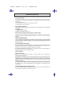
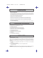
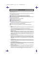
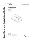
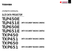
1
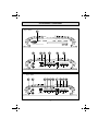
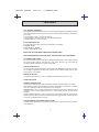
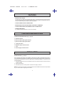
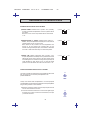
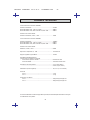
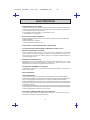
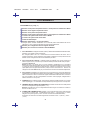
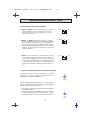
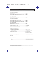
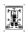
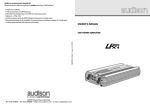
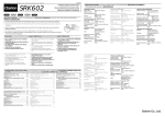
42.15
42.17
POWER AMPLIFIER, BRIDGEABLE FOR
SIMULTANEOUS STEREO/MONO
OUTPUT,
MOS-FET POWER SUPPLY,
DISCRETE COMPONENTS FINAL STAGE
OWNER'S MANUAL
BEDIENUNGSANLEITUNG
MANUEL D'EMPLOI
MANUALE D'ISTRUZIONI
MANUAL DE INSTRUCCIONES
CAR AUDIO EQUIPMENT
®
CONTENTS / INHALT / TABLE DE MATIERES / INDICE
•
•
•
•
INSTALLATION / EINBAU / INSTALLATION / INSTALLAZIONE / INSTALACION .................................................................. 3
CONTROLS AND INDICATORS / BEDIENUNGSELEMENTE UND ANZEIGEN / COMMNDES
ET INDICATEURES / CONTROLLI E INDICATORI / CONTROLES E INDICATORES .......................................................... 4
CONNECTIONS / ANSCHLUSSE / CONNEXIONS / COLLEGAMENTI / CONEXIONES ....................................................... 4
SYSTEM CHART / SYSTEM-DIAGRAMM / EXEMPLES DE SYSTEME / DIAGRAMMA DI SISTEMA /
DIAGRAMA DEL SISTEMA ................................................................................................................................................... 5-6
’’ ENGLISH ’’
INTRODUCTION ............................................................................................................................................................................ 7
PRECAUTIONS .............................................................................................................................................................................. 7
FEATURS .................................................................................................................................................................................... 8-9
CONTROLS AND INDICATORS .................................................................................................................................................... 9
INSTALLATION .............................................................................................................................................................................. 9
CONNECTIONS ........................................................................................................................................................................... 10
REGULATION AND SWITCH ..................................................................................................................................................... 11
TECHNICAL DATA ...................................................................................................................................................................... 12
’’ DEUTSCH ’’
EINFUHRUNG .............................................................................................................................................................................. 13
VORSICHT ................................................................................................................................................................................... 13
MERKMALE ............................................................................................................................................................................. 14-15
STEUERUNGEN UND ANZEIGEN ............................................................................................................................................... 15
EINBAU ........................................................................................................................................................................................ 15
ANSCHLUSSE ............................................................................................................................................................................. 16
EINSTELLUNGEN UND SCHALTUNG ........................................................................................................................................ 17
TECHNISCHE ANGABEN .......................................................................................................................................................... 18
’’ FRANCAIS ’’
INTRODUTION ............................................................................................................................................................................. 19
PRECAUTIONS ............................................................................................................................................................................ 19
CARACTERISTIQUES ............................................................................................................................................................ 20-21
CONTROLES ET INDICATEURS ................................................................................................................................................. 21
INSTALLATION ............................................................................................................................................................................ 21
CONNEXIONS ............................................................................................................................................................................. 22
REGAGES ET COMMUTATEUR .................................................................................................................................................. 23
DONNEES TECHNIQUES ........................................................................................................................................................... 24
’’ ITALIANO ’’
INTRODUZIONE .......................................................................................................................................................................... 25
PRECAUZIONI ............................................................................................................................................................................. 25
CARATTERISTICHE ............................................................................................................................................................... 26-27
CONTROLLI ED INDICATORI ..................................................................................................................................................... 27
INSTALLAZIONE .......................................................................................................................................................................... 27
COLLEGAMENTI ......................................................................................................................................................................... 28
REGOLAZIONI ED INTERRUTTORE ........................................................................................................................................... 29
DATI TECNICI .............................................................................................................................................................................. 30
’’ ESPAÑOL ’’
INTRODUCCION .......................................................................................................................................................................... 31
PRECAUCIONES ......................................................................................................................................................................... 31
CARACTERISTICAS ............................................................................................................................................................... 32-33
CONTROLES E INDICATORES ................................................................................................................................................... 33
INSTALACION .............................................................................................................................................................................. 33
CONEXIONES .............................................................................................................................................................................. 34
REGULACIONES E INTERRIPTORES ........................................................................................................................................ 35
DATOS TECNICOS ...................................................................................................................................................................... 36
2
CONNECTIONS / ANSCHLUSSE / CONNEXIONES /
COLLEGAMENTI / CONEXIONES
Fig. 2 / abb.2
1
POWER ON
MIXED MONO
DISCRETE COMPONENTS FINAL STAGE
2
3
4
5
+
+
L (m ono)
L
6
BRIDGED
+
15 A
7
BATT
GND
REMOTE
7
8
9 10
15 A
BATT
R
0.5V
2V
R
0.1V
GAIN CONTROL
Fig. 3 / abb.3
5
6
1
2
+
+
L (m ono)
R
L
3
BRIDGED
+
0.5V
2V
0.1V
GAIN CONTROL
4
4
R
GND
REMOTE
SYSTEM DIAGRAM / SYSTEM-DIAGRAMM / EXEMPLES DE SYSTEME
DIAGRAMMA DI SISTEMA / DIAGRAMA DEL SISTEMA
3-CHANNEL CONFIGURATION
Mono
Left channel
Right channel
Left
Right
Left
Right
2-CHANNEL CONFIGURATION
Left channel
Right channel
1-CHANNEL CONFIGURATION
Mono
Left channel
Note: For the other channel
another amplifier must to be
used in same way.
5
SYSTEM CHART / SYSTEM-DIAGRAMM / EXEMPLES DE SYSTEME
DIAGRAMMA DI SISTEMA / DIAGRAMA DEL SISTEMA
Two channel configuration
Audio Signal
57.00
57.00
95.83
95.83
59.10
59.10
Power Amplifier
42.15 - 42.17
59.16
LEFT
RIGHT
-
+
+
59.16
-
+
-
Three channel passive configuration
57.00
Audio Signal
95.83
57.00
95.83
59.10
59.10
59.16
59.16
Power Amplifier
42.15 - 42.17
LEFT
RIGHT
-
+
MONO
-
Coil 5mH
+
+
59.25
59.25
38
MACROM
INGLESE
42.15 - 42.17
17 FEBBRAIO 19937
INTRODUCTION
For us at MACROM the achievement of the best sound quality is one of our greatest concerns. In
buying the Digital Ready amplifier MACROM 42.15/42.17 we realize that this is also your concern.
This unit offers 70/100 Watt max. per channel at 4 Ohm or 150/200 Watt max. when mono-bridged
with pure and stable sound qualities.
This instruction manual has been prepared in order to help you to make the most of the outstanding
performances and the advanced features and functions of your new amp.
We advise you to read these instructions carefully to famialirise yourself with all the special feature
of your 42.15/42.17.
Please report any problem to your nearest MACROM dealer.
PRECAUTIONS
1. The unit may be damaged by wrong lead connection, therefore read carefully the instructions
of this manual for the correct connection of the leads.
2. The last lead to be connected is the one to the positive (+) terminal of the battery; connect this
lead only after having completed and checked all other connections.
3. Due to the power of the 42.15/42.17 it is imperative that all connections are clean and secure
in order to avoid damage to the unit.
4. Be sure to install the amplifier in a position with good air circulation and good heat dissipation.
5. In case of fuse replacement make sure to use fuses of the same amperage.
The use of fuses with the wrong amperage may seriously damage the components of the unit.
If fuses blow more than once, carefully check all electrical connections. Also have your car’s
voltage regulator checked. Do not attempt to repair the unit yourself. If repairs are ever needed,
take the unit to your MACROM dealer or to your nearest MACROM service station.
6. In order to obtain the best possible performance from this unit, make sure that the temperature
inside your car is within the range of -10° C and +60° C before you switch the unit on. Good air
circulation is essential to prevent heat build-up inside the unit.
7
MACROM
INGLESE
42.15 - 42.17
17 FEBBRAIO 19938
FEATURES
• 3/2/1 CHANNEL OPERATION
The amplifier can be operated as a stereo or a as mono-bridged amplifier thus doubling the output
power independently from the input mode; the power can be subdivided as follows, according to
your needs:
a) 70/100 Watts for each one of the two channels
b) 70/100 Watts for two stereo channels, and 150/200 Watts mono
c) 150/200 Watts for one mono channel
• INPUT MODE SELECTOR
This switch allows the user to specify the input signal to the amplifier.
a) STEREO MODE
b) LEFT MODE (L - MONO)
c) LEFT + RIGHT MODE (L+R)
• END STAGE WITH DISCRETE COMPONENTS (TRANSISTORS)
• HIGH PERFORMANCES, LOW NOISE LEVEL, PASSIVE AND ACTIVE COMPONENTS
• NO CURRENT LIMITATIONS
The current limitation circuits incorporated in traditional amplifiers may cause untimely clipping
and a low transient response. The absence of such circuits assures a low T.I.M. effect, an
excellent transient response and a perfect sound quality.
• RCA INPUT SENSITIVITY
The new amp has a 500mVsensitivity for ideal coupling with MACROM sources and, however,
it is possible to regulate the sensitivity from 100mV to 2V to facilitate coupling with any other
source present on the market.
• REMOTE ON AND OFF
On switching the head unit on or off, the amplifier is automatically switched on or off.
• ON/OFF INDICATOR
• THREEFOLD PROTECTION
Your unit is provided with three different protection devices, as befits all high-end products.
SOFT START: the amp powers gradually in order to avoid damage to the speakers in case the
head unit is switched on with the volume control set to maximum.
OVERHEATING: in case of wrong installation the unit enters the protection mode before being
damaged. As soon as the temperature returns to normal values, the unit resumes normal
operation.
OUTPUT SHORT CIRCUIT: in case of a short circuit at the speaker outlets the unit enters the
protection mode in order to avoid serious damage to the end-stage transistors. Normal operation
is resumed on eliminating the short circuit.
• CAPACITIVE/INDUCTIVE POWER SUPPLY FILTER
This filter reduces radio frequency interferences (RFI) and cuts off system noises (i.e. the whine
of the alternator).
8
MACROM
INGLESE
42.15 - 42.17
17 FEBBRAIO 19939
FEATURES
• MOS-FET Power Supply
The 42.15/42.17 's great power is obtained by means of a special C-Mos-Fet supply unit which
offers constant efficiency and requires low electrical input. The results are excellent performances,
a linear and wide frequency response with high dynamics.
• GOLD-PLATED RCA INPUT CONNECTIONS
• PROFESSIONAL GOLD-PLATED SCREW-TYPE SUPPLY TERMINALS
• GOLD-PLATED SCREW-TYPE SPEAKER OUTPUT CONNECTIONS
• SPEAKER IMPEDANCE
4 or 2 Ohm for stereo operation, 4 Ohm if mono-bridged
CONTROLS AND INDICATORS
CONTROLS AND INDICATORS (Fig. 2, page 4)
➀
➁
➂
√
➄
≈
∆
ON/OFF indicator
Stereo or Mono input signal connector
Stereo or Mono input signal selector
Input gain control
Speaker output connector board
Fuse
Power supply connector board
INSTALLATION
INSTALLATION (Fig. 1, page 3)
Due to the high output power of the amplifier a great amount of heat is generated when the unit is
in use. It is therefore necessary to install the unit in a position with good air circulation otherwise the
amp will enter the protection mode. The best place to install the amplifier is in the trunk; avoid
covering the amp.
1. Place the amplifier at the point of installation chosen and mark the position of the four securing
screws provided.
2. Drill the screw holes.
3. Place the amp in the correct position and fit the four tapping screws in.
NOTE: Connect the ground lead to a screw already fixed to the metallic chassis of the car (indicated
by * ) in order to ensure a good ground contact.
9
MACROM
INGLESE
42.15 - 42.17
17 FEBBRAIO 199310
CONNECTIONS
CONNECTIONS ( Fig. 3 Pag. 4 )
1 Positive output terminal for left speaker or positive output terminal if used in MONO
2 Negative output terminal for left speaker
3 Positive output terminal for right speaker
4 Negative output terminal for right speaker or negitive output terminal if used in MONO
5 RCA-type input connector, left channel or mono
6 RCA-type input connector, right channel
7 20/25 Ampere fuse
8 Feed terminal + 12 V to the battery
Connect this terminal directly to a positive (+) terminal of the battery by means of a lead
responding to the amplifiers power requirements.
9 Terminal for the connection of the negative ground lead
10 Terminal for REMOTE switch-on
1. Battery lead . Connect this terminal (+BAT)➇ directly to the battery cable of the car, by using
an adequately sectioned cable (yelow).
Do not connect this lead to circuits existing within the electric system of the car. In order to avoid
damage to the car it is imperative that this lead be fitted with a fuse (not supplied) as near as
possible to the car‘s battery. This connection is to be carried out last.
2. REMOTE switch-on lead (blue). Connect this lead to the remote switch-on lead or connect the
control lead of the power antenna coming from the head unit to the REMOTE terminal ➉.
NOTE: If this lead is not connected, the amplifier will not be switched on when the head unit is
switched on. If your head unit is not fitted with an outlet for a power antenna, a quick-break lever
switch (SPST) should be installed between the power source (+12 V) and the remote switchon lead and connected to the REMOTE ➉ terminal so as to allow the manual activation of the
amplifier.
3. Ground lead . Secure the ground lead to a clean spot on the car chassis and to the GND terminal
➈. Make sure that there is electric continuity between this spot and the negative terminal of the
battery. Use the shortest possible ground cable and if more than one amp should be used,
connect the relative ground to one sole point.
4. FUSE. In case of fuse replacement be sure to use fuses of the same amperage.
The use of fuses with the wrong amperage may seriously damage the components of the unit.
5. SPEAKER OUTLET TERMINALS. Be sure to keep the right polarity and phase in connecting
the speakers. This includes the control of the right polarity, positive (+) and negative (-). NOTE:
Avoid any contact between stripped wires and the ground lead.
6. RCA INPUT CONNECTORS. The line output leads of your head unit should be connected to
the RCA input connectors, respectively RCA right ≈ and RCA left ➄ , by means of a RCA
extension cable ( e.g. 90.05-90.10-90.25-90.50 by MACROM). Be sure to respect the right
channel designation: left (white) and right (red).
10
MACROM
INGLESE
42.15 - 42.17
17 FEBBRAIO 199311
ADJUSTMENTS AND SWITCHES
INPUT SELECTOR SWITCH
a) STEREO MODE. Select the "ST" (mid) position when the
amplifier is used as a 2-channel stereo system.
Note:Even in this case the connection is possible L + R -.
L (MONO)
ST
L+R
b) LEFT MODE "L - MONO". Select the "L - Mono" position when
the amplifier is used for only one channel of the stereo system
or for one bridged channel.
Note: Connect the leads coming from one speaker to the
terminals (L+ R-) in order to obtain a BTL-connection. In case
stereo output is requested, connect a second 42.15 / 42.17 in
the same way to the other speaker.
L (MONO)
ST
L+R
c) L + R MODE. Select the "L+R" position when the amplifier is
used for a subwoofer system using the right and left channels.
Thus, the two inputs are blended into one mono output signal
divided between 2 channels or, one double power channel if
the Sub Woofer is connected to the central channel L + R .
L (MONO)
ST
L+R
INPUT GAIN ADJUSTMENT CONTROL
In the mid position an input sensitivity of 500 mV is selected
corresponding to the preamplified outputs of MACROM products.
0.5V
2V
0.1V
GAIN
CONTROL
If the amplifier is to be connected to a head unit that is not of
MACROM make but is fitted with preamplified RCA outputs
proceed as follows:
a) Adjust the volume control of your head unit to 3/4 of a turn from
the maximum output level.
b) Turn the input control by means of a screwdriver and adjust
the input gain from 0.1 V to 2 V to the maximum sound level
where no distortion occurs.
0.5V
2V
0.1V
GAIN
CONTROL
11
MACROM
INGLESE
42.15 - 42.17
17 FEBBRAIO 199312
TECHNICAL DATA
42.15 STEREO Power Output
Maximum power ....................................................................... 70Wx2
Nominal RMS 4 Ohm, 1 kHz at 1% THD .................................. 45Wx2
Nominal RMS 4 Ohm, 20 Hz to 20 kHz at 0,05% THD ............ 35Wx2
BRIDGED Power Output
Maximum power, 4 Ohm, 1 kHz ............................................... 150W
42.17 STEREO Power Output
Maximum power ....................................................................... 100Wx2
Nominal RMS 4 Ohm, 1 kHz at 1% THD .................................. 65Wx2
Nominal RMS 4 Ohm, 20 Hz to 20 kHz at 0,05% THD ............ 50Wx2
BRIDGED Power Output
Maximum power, 4 Ohm, 1 kHz ............................................... 200W
Frequency response +0, -1dB .................................................. 10-50,000 Hz
S/N (signal to noise ratio) INFA-weighted ................................ 105 dB
Input sensitivity/Impedance
(for nominal power output)
Control in mid position ........................................................ 500 mV/10k Ohm
Variable control .................................................................. 100-2,000mV/10k Ohm
Speaker impedance .................................................................. 4 or 2 Ohm (stereo)
4 Ohm (bridged, mono)
Power supply (negative ground) 14.0V DC (11-16 V permissible)
Net Weight
42.15 ................................................................................... 1.3 kg
42.17 ................................................................................... 1.5 kg
Chassis size
42.15 ................................................................................... 150(L)x50(H)x217(P) mm
42.17 ................................................................................... 180(L)x50(H)x217(P) mm
Due to continuing improvement, the features and the design are subject to change without notice.
12
MACROM
TEDESCO
42.15 - 42.17
17 FEBBRAIO 1993
EINFÜHRUNG
Für uns von MACROM ist die Soundqualität eines unserer Hauptziele. Die Tatsache, daß Sie sich
für den Digital-Ready Verstärker 42.15/42.17 von MACROM entschieden haben, bedeutet, daß Sie
ebenso denken.
Ihr Verstärker hat eine Leistung von 70/100 Watt MAX pro Kanal bei 4 Ohm oder von 150/200 Watt
max. mono-gebridged, mit einem sauberen, stabilen Klang. Diese Bedienungsanleitung soll Sie
dabei unterstützen, die außergewöhnlichen Leistungen und alle technologischen Eigenschaften
Ihres neuen Leistungsverstärkers aufs Beste zu nutzen.
Wir empfehlen Ihnen, diese Bedienungsanleitung sorgfältig durchzulesen, um sich mit den
einzelnen Bedienungselementen und Funktionen des 42.15/42.17 vertraut zu machen. Wenden
Sie sich für jedes Problem vertrauensvoll an Ihren MACROM-Vertragshändler.
VORSICHTSMASSNAHMEN
1. Jeder falsche Anschluß der Kabel kann zu Beschädigungen des Geräts führen. Lesen Sie
aufmerksam die vorliegenden Anleitungen für den Geräteanschluß.
2. Schließen Sie das Batteriekabel als letztes an den Batteriepol (+) an, nachdem alle anderen
Verbindungen vollständig ausgeführt und kontrolliert worden sind.
3. Aufgrund der hohen Leistung des Verstärkers 42.15/42.17 müssen alle Verbindungen sauber
und fest sein, um Beschädigungen zu vermeiden.
4. Installieren Sie den Verstärker in einer Position mit ausreichender Luftzirkulation, wo die Wärme
gut abgestrahlt werden kann.
5. Sollte das Auswechseln von Sicherungen erforderlich sein, so vergewissere man sich, daß eine
Sicherung mit derselben Amperezahl verwendet wird.
Die Verwendung von Sicherungen mit falscher Amperezahl kann zu schweren Beschädigungen
der Verstärkerteile führen.
Sollten die Sicherungen mehr als einmal durchbrennen, so muß man die elektrischen Anschlüsse
auf Kurzschluß prüfen. Den Spannungsregler des Fahrzeuges ebenfalls überprüfen lassen.
Versuchen Sie auf keinen Fall, das Gerät selbst zu reparieren. Wenden Sie sich an Ihren
MACROM-Händler oder an eine MACROM-Dienststelle.
6. Vor dem Einschalten des Gerätes sicherstellen, daß die Temperatur im Fahrzeugraum
zwischen -10° C und +60° C liegt, um die besten Betriebsbedingungen zu gewährleisten. Bei
großer Hitze besonders gut auf ausreichende Luftzirkulation im Fahrzeug achten, damit kein
Wärmestau in dem Gerät auftritt.
13
MACROM
TEDESCO
42.15 - 42.17
17 FEBBRAIO 1993
EIGENSCHAFTEN
• 3/2/1-KANALBETRIEB
Der Verstärker kann jederzeit als Stereoverstärker oder gebridged eingesetzt werden, wobei er
unabhängig vom Eingangsmodus die doppelte Leistung abgibt, die folgendermaßen aufgeteilt
werden kann:
a) 70/100 Watt pro Kanal
b) 70/100 Watt pro Stereokanal und 150/200 W Sinus Mono
c) 150/200 Watt für einen Monokanal
• EINGANGSMODUSWÄHLER
Dieser Schalter bietet dem Bediener die Möglichkeit, das Eingangssignal des Verstärkers
einzustellen.
a) STEREOMODUS
b) LINKER MODUS (L-MONO)
c) LINKER + RECHTER MODUS (L+R
• ENDSTUFE MIT DISKRETEN KOMPONENTEN (TRANSISTOREN)
• HOHE LEISTUNGEN, NIEDRIGER GERÄUSCHPEGEL, PASSIVE UND AKTIVE KOMPONENTEN
• KEINE STROMBEGRENZUNG
Die Strombegrenzungskreisläufe der herkömmlichen Verstärker können ein verfrühtes Clipping
und eine niedrigere Übergangsantwort verursachen. Die Abwesenheit dieser Kreisläufe
gewährleistet einen niedrigen T.I.M.-Effekt, eine ausgezeichnete Übergangsantwort und ein
perfektes Klangbild.
• RCA-EINGANGSEMPFINDLICHKEIT
Der neue Verstärker hat eine Empfindlichkeit von 500mV für den optimalen Anschluss eines
MACROM-Gerätes.Es besteht die Möglichkeit die Empfindlichkeit von 100mV auf 2V zu
regulieren, um den Anschluss von anderen Fabrikaten zu erleichtern.
• EIN- UND AUSSCHALTEN- AUF DISTANZ. Der Verstärker wird bei Ein- oder Ausschalten des
Hauptgeräts automatisch ein- oder ausgeschaltet.
• EIN/AUS-ANZEIGE
• DREIFACHER SCHUTZ
Wie es sich für High-End-Geräte gehört, ist dieses Gerät mit drei verschiedenen
Schutzvorrichtungen versehen:
SOFT START: Der Verstärker gibt seine Leistung allmählich ab, um die Lautsprecher nicht zu
beschädigen, wenn das Hauptgerät aus Versehen mit höchster Lautstärke eingeschaltet wird.
ÜBERHITZUNG: Bei Installationsfehlern tritt das Gerät in den Schutzstatus, bevor es beschädigt
werden kann. Sobald die Temperatur wieder auf einen normalen Wert sinkt, wird der Betrieb
wieder aufgenommen.
KURZSCHLUß IM AUSGANG: Im Falle von Kurzschlüssen an den Lautsprecherausgängen tritt
das Gerät in den Schutzstatus, um die Beschädigung der Endstufentransistoren zu vermeiden.
Die Rückkehr zum normalen Betriebsstatus erfolgt automatisch nach Beseitigung des
Kurzschlusses.
• KAPAZITIVER/INDUKTIVER STÖRUNGSFILTER
Für einen niedrigen Pegel der Radiofrequenzstörungen (RFI) und die Unterdrückung der
Störungsquellen des Wagens (z.B. der Lichtmaschine).
14
MACROM
TEDESCO
42.15 - 42.17
17 FEBBRAIO 1993
EIGENSCHAFTEN
• MOS-FET-VERSORGUNG
Die hohe Leistung des 42.15/42.17 wird durch die Verwendung eines besonderen
Versorgungsgerätes mit C-Mos-Fet erhalten, das eine konstante Leistung und höchste Effizienz
bei niedriger Stromaufnahme bietet. Als Ergebnis erhält man ausgezeichnete Leistungen, einen
linearen, breiten Frequenzgang bei hoher Dynamik.
• VERGOLDETE RCA-EINGANGSKONTAKTE
• VERGOLDETE PROFESSIONELLE STROMANSCHLUß-SCHRAUBKONTAKTE
• VERGOLDETE SCHRAUBKONTAKTE AN DEN LAUTSPRECHERAUSGÄNGEN
• LAUTSPRECHERIMPEDANZ
4 oder 2 Ohm in der Stereo-Betriebsart, 4 Ohm bei gebridgtem Verstärker in Mono-Betriebsart.
STEUERUNGEN UND ANZEIGEN
STEUERUNGEN UND ANZEIGEN (Abb. 2, Seite 4)
➀
➁
➂
√
➄
≈
∆
EIN/AUS-Statusanzeige
Anschluß des Stereo oder Mono-Eingangssignals
Wählschalter für Stereo oder Mono-Eingangssignal
Eingangsgewinnsteuerung
Anschlußbrett Lautsprecherausgänge
Sicherung
Versorgungs-Anschlußklemmen
INSTALLATION
INSTALLATION (Abb. 1, Seite 3)
Aufgrund der hohen Ausgangsleistung des Verstärkers wird bei Betrieb des Geräts viel Wärme
erzeugt. Es ist somit erforderlich, das Gerät dort einzubauen, wo ausreichende Luftzirkulation
vorhanden ist. Eine optimale Stelle ist der Kofferraum, wo der Verstärker jedoch nicht bedeckt
werden darf.
1. Das Gerät an der ausgewählten Stelle aufsetzen und die Position der vier Schrauben
markieren.
2. Die Schraubenlöcher bohren.
3. Den Verstärker in Position bringen und mit den beigelieferten Blechschrauben befestigen.
MERKMALE: Man verwende eine bereits am metallischen Fahrwerk des Wagens angebrachte
Schraube (in der Abbildung mit einem * gekennzeichnet) für einen guten Massekontakt.
15
MACROM
TEDESCO
42.15 - 42.17
17 FEBBRAIO 1993
ANSCHLÜSSE
ANSCHLÜSSE (Abb. 3, S. 4)
1 Anschlußklemme für den positiven Ausgang des linken Lautsprechers oder positiven
Ausgang bei Mono-Betriebsart
2 Anschlußklemme für den negativen Ausgang des linken Lautsprechers
3 Anschlußklemme für den positiven Ausgang des rechten Lautsprechers
4 Anschlußklemme für den negativen Ausgang des rechten Lautsprechers oder negativen
Ausgang bei Mono-Betriebsart
5 RCA-Eingangsanschluß linker Kanal oder Mono
6 RCA-Eingangsanschluß rechter Kanal
7 Sicherungen von 20/25 Ampere
8 Versorgungsklemme +12 V zur Batterie
Man schließe diese Klemme direkt an den Pluspol der Batterie an, wobei
ein Kabel mit
einem Querschnitt zu verwenden ist, der der Leistung des Verstärkers entspricht.
9 Klemme für den Anschluss des negativen Massekabel
10 Klemme für den Anschluss an REMOTE-Ein- und Ausschalten auf Entfernung
1. Batteriekabel (+ BAT) ➇ (gelb). Man verbinde dieses Kabel direkt mit dem Batteriekabel des
Wagens.
Um das Fahrzeug zu schützen ist es sehr wichtig, das man sehr nahe der Batterie eine
Sicherung (nicht mitgeliefert) einführt. Dieser Anschluss muss zuletzt erfolgen.
2. Kabel für Ferneinschaltung (REMOTE (blau). Man verbinde dieses Kabel mit dem Ferneinschaltkabel oder dem Steuerkabel für die elektrische Antenne des Hauptgeräts mit der
REMOTE-Klemme➉ .
Merkmale: Sollte dieses Kabel nicht angeschlossen werden, so wird der Verstärker bei
Einschalten des Hauptgeräts nicht eingeschaltet. Verfügt Ihr Hauptgerät nicht über einen
Ausgang für eine elektrische Antenne, so muß ein schnellauslösender Hebelschalter (SPST)
zwischen die Stromquelle (+12 V) und das REMOTE-Einschaltkabel geschaltet und an die
REMOTE-Klemme ➉ angeschlossen werden, damit der Verstärker manuell ein-und
ausgeschaltet werden kann.
3. Massekabel (GND) (schwarz). Das Massekabel an eine saubere, freie Metallstelle an dem
Fahrwerk und an der GND-Klemme ➈. befestigen. Man vergewissere sich, daß ein
Stromdurchgang zwischen dem Anschlußpunkt und dem negativen Pol der Batterie besteht.
Man verwende das Massekabel so kurz als möglich und sollten mehrere Endstufen
angeschlossen werden, soll man die verschiedenen Massen an einen einzigen Punkt
anschliessen.
4. SICHERUNG (GND) (schwarz). Sollte das Auswechseln von Sicherungen erforderlich sein, so
vergewissere man sich, daß eine Sicherung mit derselben Amperezahl verwendet wird. Die
Verwendung von Sicherungen mit falscher Amperezahl kann zu schweren Beschädigungen
von Verstärkerteilen führen.
5. LAUTSPRECHERAUSGANGSANSCHLUß. Man vergewissere sich, daß die richtige Polarität
und Phase beim Anschluß der Lautsprecher eingehalten werden. Dies schließt die Kontrolle der
richtigen positiven (+) und negativen (-) Polarität ein.
Merkmale: Der Kontakt zwischen nicht isolierten Kabeln unter sich und mit dem Massekabel
ist absolut zu vermeiden.
6. RCA-EINGANGSANSCHLUß. Die Linienausgangskabel Ihres Hauptgeräts werden mit den
RCA-Eingangsanschlüssen, verbunden, jeweils RCA ≈ rechts und RCA ➄ links, unter
Verwendung von RCA-Verlängerungskabeln (90.05-90.10-90.25-90.50 von MACROM). Man
vergewissere sich des korrekten Kanalanschlusses: links (weiß) und rechts (rot).
16
MACROM
TEDESCO
42.15 - 42.17
17 FEBBRAIO 1993
EINSTELLUNGEN UND SCHALTER
EINGANGSWÄHLSCHALTER
a) STEREOMODUS. Den Schalter in die Mittelposition "ST"
stellen, wenn der Verstärker im 2-Kanal-Stereobetrieb
eingesetzt wird.
Merkmale: Auch in diesem Falle ist der Anschluss der
Mittelposition möglich L+R.
L (MONO)
ST
L+R
b) LINKER MODUS "L-MONO". Den Schalter in die Position
"L-MONO" stellen, wenn der Verstärker nur für einen
Eingangskanal eingesetzt wird.
Merkmale: Man verbinde die von einem Lautsprecher
kommenden Kabel mit den Klemmen (L+ R-), um eine BTLVerbindung (gebridged) zu erhalten. Wünscht man ein StereoKlangbild, so muß ein weiterer 42.15/42.17 verwendet werden,
der auf dieselbe Art mit dem anderen Lautsprecher verbunden
werden muß.
L (MONO)
ST
L+R
c) L+R-MODUS. Den Schalter in die Position "L+R" stellen, wenn
der Verstärker zur Steuerung eines Tieftönersystems
verwendet wird, das den rechten und linken Kanal in Anspruch
nimmt. Die beiden Eingänge werden so gemischt, dass man
ein einziges Mono Ausgangssignal erhält, verteilt auf die
beiden Kanäle oder auf einen Kanal zu doppelter Leistung
wenn der Sub Woofer an die Mittelposition (L+R)
angeschlossen ist.
L (MONO)
ST
L+R
EINSTELLUNG DES EINGANSGEWINNS
Die Mittelposition dient zur Auswahl einer Eingangsempfindlichkeit
von 500mVdie demVorverstärkerausgang der MACROM-Fabrikate
entspricht.
0.5V
2V
0.1V
GAIN
CONTROL
Will man einen Verstärker mit einem Hauptgerät verbinden, das
kein MACROM-Fabrikat ist, jedoch einen vorverstärkten RCAAusgang besitzt, soll man wie folgt vorgehen:
a) Die Lautstärke des Hauptgerätes auf zirka 3/4 Drehung vom
max. Lautstärkepegel einstellen.
b) Die Eingangssteuerung mit einem Schraubenzieher auf
0.1V-2Vdrehen um den maximalen Lautstärkepegel ohne
Verzerrung zu erhalten.
0.5V
2V
0.1V
GAIN
CONTROL
17
MACROM
TEDESCO
42.15 - 42.17
17 FEBBRAIO 1993
TECHNISCHE ANGABEN
42.15 STEREO-Ausgangsleistung
Maximale Leistung .................................................................... 70Wx2
RMS Nennleistung bei
4 Ohm, 1 kHz bei 1% THD ....................................................... 45Wx2
4 Ohm, 20 Hz bis 20 kHz bei 0,05% THD ................................ 35Wx2
Ausgangsleistung bei GEBRIDGTEM Verstärker
Maximale Leistung bei 4 Ohm, 1 kHz ....................................... 150W
42.17 STEREO-Ausgangsleistung
Maximale Leistung .................................................................... 100Wx2
RMS Nennleistung bei
4 Ohm, 1 kHz bei 1% THD ...................................................... 65Wx2
4 Ohm, 20 Hz bis 20 kHz bei 0,05% THD ............................... 50Wx2
Ausgangsleistung bei GEBRIDGTEM Verstärker
Maximale Leistung bei 4 Ohm, 1 kHz ....................................... 200W
Frequenzgang +0, -1 dB ........................................................... 10-50.000 Hz
Geräuschabstand, INFA-gewägt .............................................. 105 dB
Eingangsempfindlichkeit/Impedanz
(für Ausgangs-Nennleistung)
Steuerung in Mittelposition ................................................. 500 mV/10k Ohm
Variable Steuerung ............................................................ 100-2.000 mV/10k Ohm
Lautsprecherimpedanz ............................................................. 4 oder 2 Ohm (Stereo)
4 Ohm (gebridged, Mono)
Stromversorgung (negative Masse) 14,0 V DC (11-16 V) zulässig
Nettogewicht
42.15 ................................................................................... 1,3 kg
42.17 ................................................................................... 1,5 kg
Abmessungen des Chassis
42.15 ................................................................................... 150(L)x50(H)x217(T) mm
42.17 ................................................................................... 180(L)x50(H)x217(T) mm
Änderungen der technischen Daten und des Designs bleiben zwecks Verbesserung vorbehalten.
18
MACROM
FRANCESE
42.15 - 42.17
17 FEBBRAIO 1993
19
INTRODUCTION
Pour nous de MACROM le but le plus important, que nous poursuivons, est celui d’atteindre la
meilleure qualité sonore. Le fait que vous ayez choisi le standard industriel, l’amplificateur 42.15/
42/17 de MACROM, signifie que vous êtes d’accord avec nous.
Votre unité vous offre 70/100 Watt de puissance par canal à 4 Ohm ou bien 150/200 Watt max. à
pont en mono, tout en gardant une exceptionnelle propreté et stabilité sonore. Ce manuel
d’instruction a été préparé pour vous aider à profiter au maximum des performances exceptionnelles, des caractéristiques technologiques avancées et du rendement élevé de votre nouveau
amplificateur de puissance.
Lisez attentivement ce manuel d’instruction pour vous familiariser avec toutes les caractéristiques
spéciales et les fonctions de votre nouveau modèle 42.15/42.17. En cas de doute adressez-vous
à votre revendeur autorisé MACROM.
PRECAUTIONS
1. Toute mauvaise connexion des fils pourrait endommager votre unité; lire attentivement les
instructions pour la connexion des fils données dans ce manuel .
2. Il faut connecter le fil de la batterie au terminal (+) de la batterie même en dernier et seulement
après avoir terminé et contrôlé toutes les autres connexions.
3. A cause de la puissance du 42.15/42.17 il est indispensable que toutes les connexions soient
bien propres et solides, autrement l’unité pourrait remporter des dommages.
4. Assurez-vous d’installer l’appareil dans une position qui garantisse une bonne circulation d’air
et une bonne dissipation de la chaleur.
5. Si des fusibles doivent être remplacés, il faut s’assurer qu’ils soient remplacés avec des fusibles
ayant le même ampérage.
En cas d’utilisation des fusibles avec un autre ampérage, les composants de l’appareil
pourraient être gravement endommagés.
Si les fusibles devaient sauter plus d’une fois, contrôlez soigneusement toutes les connexions
électriques. Faire contrôler de plus le régulateur de voltage de votre voiture. Evitez de réparer
vous-mêmes l’appareil. Confiez la réparation éventuelle au distributeur MACROM ou au centre
d’assistance MACROM de la zone.
6. Pour assurer les meilleures performances de votre unité, ayez soin que la température à
l’intérieur de la voiture soit comprise entre -10° C et +60°C avant d’allumer l’appareil. Une bonne
ventilation est indispensable pour éviter la surchauffe de l’appareil.
19
MACROM
FRANCESE
42.15 - 42.17
17 FEBBRAIO 1993
20
CARACTERISTIQUES
• FONCTIONNEMENT A 3/2/1 CANAUX
L’amplificateur peut être utilisé comme amplificateur de puissance à deux canaux ou bien ponté,
doublant ainsi la puissance qui, à l’occurence, peut être répartie de la façon suivante,
indépendammant du mode d’entrée:
a) 70/100 Watt pour chacun des deux canaux
b) 70/100 Watt sur deux canaux stéréo, et 150/200 Watt en mono
c) 150/200 Watt sur un canal mono.
• SELECTION DU MODE D’ENTREE
Cet interrupteur permet à l’utilisateur de spécifier le signal d’entrée de l’amplificateur.
a) MODE STEREO
b) MODE GAUCHE (L - MONO)
c) MODE GAUCHE+DROIT (L+R)
• ETAGE FINAL A COMPOSANTS DISCRETS (TRANSISTORS)
• HAUTES PERFORMANCES, BASSES RUMEURS, COMPOSANTS PASSIFS ET ACTIFS
• AUCUNE LIMITATION DE COURANT
Les circuits limiteurs de courant qui sont incorporés dans les amplificateurs traditionnels peuvent
provoquer un clipping prématuré et une réponse transitoire inférieure. L’absence des tels circuits
dans la section assure un bas effet T.I.M., une excellente réponse transitoire et une parfaite
qualité sonore.
• SENSIBILITE D’ENTREE RCA
Quand l'amplificateur est nouveau il a une sensibilité de 500mV pour l'idéale connexion avec des
sources MACROM. En tout cas il est possible de régler la sensibilité entre 100mV et 2V pour une
connexion facile avec les autres sources présentes sur le marché.
• ALLUMAGE ET EXTINCTION A DISTANCE
L’amplificateur s’allume et s’éteint automatiquement en allumant et éteignant l’unité principale.
• INDICATEUR ALLUME/ETEINT
• TRIPLE PROTECTION
Votre unité est équipée de trois protections différentes, comme il se doit pour un appareil de haute
classe.
SOFT START: l’amplificateur entre en fonction graduellement pour ne pas endommager les hautparleurs, si par inadvertance l’unité principale est allumée avec le volume au maximum.
SURCHAUFFE: en cas d’erreurs d’installation, l’unité entre en état de protection avant de subir
des dommages. Dès que la température retourne à des valeurs normales, l’unité reprend sont
fonctionnement normal.
COURT CIRCUIT A LA SORTIE: en cas de court-circuit à la sortie des haut-parleurs, l’unité entre
en état de protection pour prévenir des sérieux dommages aux transistors finaux. Elle retourne
automatiquement à l’état de fonctionnement normal lorsque le court-circuit est éliminé.
• FILTRE D’ALIMENTATION CAPACITIVE/INDUCTIVE
Pour obtenir un bas niveau d’interférence des fréquences radio (RFI) et pour l’immunité aux bruits
du système (par exemple, à l’hululement de l’alternateur).
20
MACROM
FRANCESE
42.15 - 42.17
17 FEBBRAIO 1993
21
CARACTERISTIQUES
• ALIMENTATEUR MOS-FET
La puissance élevée du 42.15/42.17 est obtenue grâce à l’emploi d’un alimentateur spécial CMos-Fet pour obtenir un rendement constant, une efficience élevée en faveur d’une absorption
mineure de courant. Le résultat: des performances exceptionnelles, une réponse en fréquence
linéaire et ample avec une dynamique élevée.
• TERMINAUX D’ENTREE RCA DORES
• TERMINAUX D’ALIMENTATION PROFESSIONNELS A VIS, DORES
• TERMINAUX DE SORTIE DES HAUT-PARLEURS A VIS, DORES
• IMPEDANCE HAUT- PARLEURS
4 ou 2 Ohm, si utilisé en stéréophonie, 4 Ohm, si utilisé ponté en monophonie.
CONTROLES ET INDICATEURS
CONTROLES ET INDICATEURS (Fig. 2 page 4)
➀
➁
➂
√
➄
≈
∆
Indicateur d’état ALLUME/ETEINT
Connecteur du signal d’entrée stéréo ou mono
Sèlecteur du signal d’entrée stéréo ou mono
Contrôle du gain à l’entrée
Plaque à bornes sorties haut-parleurs
Fusible
Plaque à bornes de l’alimentation
INSTALLATION
INSTALLATION (Fig. 1 page 3)
A cause de la sortie en haute puissance de l’amplificateur, il se produit une grande quantité de
chaleur pendant l’utilisation de l’unité. Il est donc nécessaire d’installer l’unité dans un lieu où il y
a une bonne circulation d’air, autrement l’amplificateur se mettra en état de protection. Un des lieux
les mieux indiqués est le coffre, où il faut évidemment éviter de couvrir l’amplificateur avec la
moquette ou autre chose.
1. Appuyer l’unité à l’endroit choisi et marquer la position des quatre vis de fixage.
2. Pratiqer les trous pour les vis.
3. Mettre l’amplificateur en position et fixer les quatre vis autofileteuses.
NOTE: Utilisez une vis déjà installée sur la partie métallique de la voiture (indiquée par un * dans
la figure) pour assurer un bon contact à la terre.
21
MACROM
FRANCESE
42.15 - 42.17
17 FEBBRAIO 1993
22
CONNEXIONS
CONNEXIONS (Fig. 3, pag. 4)
1 Borne sortie positive haut-parleur gauche ou sortie positive, si utilisé en MONO
2 Borne sortie négative haut-parleur gauche
3 Borne sortie positive haut-parleur droit
4 Borne sortie négative haut-parleur droit ou sortie nègative, si utilisé en MONO
5 Connecteur d’entrée RCA, canal gauche ou MONO
6 Connecteur d’entrée RCA, canal droit
7 Fusible de 20/25 Ampères
8 Borne d’alimentation +12 Volt à la batterie
Relier cette borne directement au terminal positif (+) de la batterie de la voiture en utilisant un
câbleavec une section adéquate à la puissance de l’amplificateur.
9 Borne pour la connexion du câble négatif de mise à la terre
10 Borne pour l’allumage à distance REMOTE
1. Fil de la batterie . Reliez le terminal (+BAT)➇ avec le fil (jaune) de la batterie de la voiture.
Ce fil ne doit pas être relié avec les circuits existant dans le système électrique de la voiture.
Il est très important pour la protection de la voiture que ce fil ait un fusible, qui doit être très près
de la batterie. Cette connexion doit se faire en dernier.
2. Fil d’allumage à distance (REMOTE) (bleu). Relier ce fil au fil d’allumage à distance ou bien
relier le fil de commande de l’antenne électrique provenant de l’unité principale à la borne
REMOTE➉ .
NOTE: Si ce fil n’est pas relié, l’amplificateur ne s’allume pas en allumant l’unité principale. Si
votre unité principale ne dispose pas d’une sortie pour l’antenne électrique, il faut relier un
interrupteur à levier à déclenchement rapide (SPST) entre la source d’allumage (+12 V) et le
fil d’allumage à distance qui doit être relié à la borne REMOTE ➉ pour effectuer l’allumage
manuel de l’amplificateur.
3. Câble de mise à la terre . Fixez le câble de mise à la terre (Noir)solidement à un point propre
sur la partie métallique du châssis de la voiture et à la borne GND➈ . Veillez à ce que le point
choisi présente une continuité électrique avec le terminal négatif de la batterie.
Utiliser le cable de mise à la terre le plus court possible et dans le cas ou plusieurs amplificateurs
doivent être employés, relier ensemble tous les fils de mise à la terre des amplificateurs.
4. FUSIBLE. Si des fusibles doivent être remplacés, il faut s’assurer qu’ils soient remplacés avec
des fusibles ayant le même ampérage.
En cas d’utilisation des fusibles avec un autre ampérage, les composants de l’appareil
pourraient être gravement endommagés.
5. TERMINAUX DE SORTIE DES HAUT-PARLEURS. Assurez-vous d’observer la bonne polarité
et la phase pendant la connexion des haut-parleurs. Ceci inclu le contrôle de la bonne polarité,
positive (+) et négative (-).
NOTE: Ne permettez pas aux fils non isolés d’entrer en contact avec le fil de mise à la terre ou
entre eux.
6. CONNECTEURS D’ENTREE RCA. Les fils de sortie Pre en ligne de votre unité principale
doivent être reliés aux connecteurs d’entrée RCA , respectivement RCA≈ droit et RCA➄
gauche, en utilisant les câbles de rallonge RCA (p.e.90.05-90.10-90.25-90.50 de MACROM).
Assurez-vous d’observer la désignation correcte du canal: gauche à gauche (blanc), droit à
droite (rouge).
22
MACROM
FRANCESE
42.15 - 42.17
17 FEBBRAIO 1993
23
REGLAGES ET INTERRUPTEURS
INTERRUPTEUR DE SELECTION D’ENTREE
a) MODE STEREO. Sélectionnez la position "ST" (centrale),
lorsque vous utilisez l’amplificateur comme un système stéréo
à 2 canaux.
Note:dans ce cas aussi il est possible relier le canal central
L+R-
L (MONO)
ST
L+R
b) MODE GAUCHE "L - MONO". Sélectionnez la position "L MONO", lorsque l’amplificateur est utilisé pour un seul canal du
système stéréo ou pour un canal ponté.
Note: Reliez les fils provenant d’un seul amplificateur aux
bornes (L+ R-) pour obtenir une connexion BTL. Si vous
désirez une image stéréophonique, il faut utiliser un deuxième
42.15/42.17 relié de la même façon à l’autre haut-parleur.
L (MONO)
ST
L+R
c) MODE "L+R." Mettez l’interrupteur dans la position "L+R",
lorsque l’amplificateur est utilisé pour un système de subwoofer
utilisant les canaux droit et gauche. Les deux entrées seront
ainsi mélangées et l’on obtient un seul signal monophonique de
sortie distribué sur deux canaux ou sur un canal de double
puissance si le Sub Woofer est relié au canal central L + R -.
L (MONO)
ST
L+R
CONTROLE DE REGLAGE DU GAIN A L’ENTREE
La position centrale sert à sélectionner la sensibilité d’entrée à 500
mV, qui correspond à la sortie de préamplification des
produits MACROM.
0.5V
2V
0.1V
GAIN
CONTROL
Lorsque vous désirez relier l’amplificateur à une unité principale
non-MACROM, mais qui toutefois possède des sorties préamplifiées
du type RCA,procedez en cette manière:
a) Réglez le contrôle du volume de votre unité principale à 3/4 de
tour du niveau maximum de sortie.
b) Tournez le contrôle d’entrée avec un tournevis et réglez le gain
à l’entrée, de 0,1V á 2V, au niveau sonore maximum, sans qu’il
y ait alcune distorsion.
0.5V
2V
0.1V
GAIN
CONTROL
23
MACROM
FRANCESE
42.15 - 42.17
17 FEBBRAIO 1993
24
DONNEES TECHIQUES
42.15 Puissance de sortie en STEREO
Puissance maximale ................................................................. 70 Wx2
Nominale RMS 4 Ohm, 1 kHz à 1% THD ................................. 45Wx2
Nominale RMS 4 Ohm, 20 Hz à 20 kHz à 0,05% THD ............ 35Wx2
Puissance de sortie A PONT
Puissance maximale, 4 Ohm, 1 kHz ........................................ 150W
42.17 Puissance de sortie en STEREO
Puissance maximale ................................................................. 100Wx2
Nominale RMS 4 Ohm, 1 kHz à 1% THD ................................. 65Wx2
Nominale RMS 4 Ohm, 20 Hz à 20 kHz à 0,05% THD ............ 50Wx2
Puissance de sortie A PONT
Maximum, 4 Ohm, 1 kHz .......................................................... 200W
Réponse en fréquence +0, -1dB .............................................. 10-50.000 Hz
Rapport signal/bruit, pesé INFA ............................................... 105 dB
Sensibilité d’entrée/impédance
(pour la sortie en puissance nominale)
Contrôle avec position centrale .......................................... 500 mV/10k Ohm
Contrôle variable ................................................................ 100-2.000 mV/10k Ohm
Impédance des haut-parleurs ................................................... 4 ou 2 Ohm (stéréo)
............................................................................................ 4 Ohm (à pont, mono)
Alimentation (à terre négative) ................................................. 14,0 V cc (11-16 V admis)
Poids net
42.15 ................................................................................... 1,3 kg
42.17 ................................................................................... 1,5 kg
Dimensions du châssis
42.15 ................................................................................... 150(L)x50 (H)x217(P) mm
42.17 ................................................................................... 180(L)x50 (H)x217(P) mm
A cause d’améliorations continues apportées au produit, les caractéristiques et le dessin sont sujets
à modifications sans préavis.
24
MACROM
ITALIANO
42.15 - 42.17
17 FEBBRAIO 1993
25
INTRODUZIONE
Per noi della MACROM, la cosa più importante è il raggiungimento della miglior qualità sonora. Il
fatto che Voi abbiate scelto l`amplificatore Digital Ready 42.15 / 42.17 della MACROM, significa che
anche Voi la pensiate come noi.
La vostra unità è in grado di offrirvi 70 /100 Watt MAX per canale a 4 Ohm o 150 /200 Watt MAX
a ponte in mono per un suono pulito e stabile. Questo manuale di istruzioni è stato preparato per
aiutarvi a sfruttare al massimo le prestazioni eccezionali e tutte le caratteristiche di avanzata
tecnologia e di alto rendimento del vostro nuovo amplificatore di potenza.
Leggete questo manuale di istruzioni attentamente per familiarizzare con tutte le caratte-ristiche
speciali e le funzioni del vostro nuovo modello 42.15 / 42.17. In caso di dubbi, rivolgetevi al nostro
rivenditore autorizzato MACROM.
PRECAUZIONI
1 Ogni collegamento scorretto dei fili potrebbe danneggiare l'unità. Leggete attentamente le
istruzioni per il collegamento dei fili fornite in questo manuale.
2. Collegare per ultimo il filo della batteria al terminale (+) della stessa e solo dopo aver completato
e controllato tutti gli altri collegamenti.
3. A causa della potenza del 42.15 / 42.17 è indispensabile che tutti i collegamenti siano puliti e
ben sicuri altrimenti potrebbero risultare dei danni.
4. Assicuratevi di installare l'amplificatore in una posizione nella quale sia garantita una buona
circolazione dell'aria e una buona dissipazione del calore.
5. Qualora doveste sostituire dei fusibili assicuratevi di sostituirli con fusibili di identico amperag
gio.L'impiego di fusibili sbagliati potrebbe comportare gravi danni ai componenti.
Se i fusibili dovessero saltare più di una volta controllare accuratamente tutti i collegamenti
elettrici. Fare controllare inoltre il regolatore di voltaggio della Vostra auto. Evitare di riparare
l'unità Voi stessi. Affidare l'eventuale riparazione al distributore MACROM o al centro di
assistenza MACROM di zona.
6. Per assicurare le migliori prestazioni della Vostra unità fare in modo che la temperatura
all'interno dell'automobile sia compresa fra i -10° C ed i +60° C prima di accendere l'unità.
Una buona ventilazione è indispensabile per evitare surriscaldamenti all'interno dell'unità.
25
MACROM
ITALIANO
42.15 - 42.17
17 FEBBRAIO 1993
26
CARATTERISTICHE
•
FUNZIONAMENTO A 3/2/1 CANALI
L'amplificatore ha sempre la possibilità di essere utilizzato in Stereo o ponticellato raddoppiando
la potenza indipendentemente dal modo d'ingresso, all'occorrenza ripartita nei seguenti modi:
a) 70/100 Watt per ciascuno dei due canali.
b) 70/100 Watt su due canali stereo, e 150/200 Watt in mono.
c) 150/200 Watt su un canale mono.
•
SELETTORE DEL MODO DI INGRESSO
Questo interruttore permette all`utente di specificare ilsegnale d'ingresso dell`amplificatore.
a) MODO STEREO
b) MODO SINISTRO ( L- MONO )
c) MODO SINISTRO + DESTRO ( L+R )
•
STADIO FINALE A COMPONENTI DISCRETI (TRANSISTORS)
•
ALTA PRESTAZIONE, BASSO RUMARE, COMPONENTI PASSIVI E ATTIVI
•
NESSUNA LIMITAZIONE DI CORRENTE
I circuiti di limitazione della corrente, che sono incorporati negli amplificatori convenzionali,
possono causare un clipping prematuro ed un inferiore risposta transiente. L`assenza tali
circuiti nella sezione, assicura un effetto T.I.M. basso, un eccellente risposta transiente ed
una perfetta qualità sonora.
•
SENSIBILITA' DI INGRESSO RCA
L'amplificatore nuovo, ha la sensibilità a 500 mV per l'ideale accoppiamento con sorgenti
MACROM è comunque possibile regolare la sensibilità da 100mV a 2V per un facile
accoppiamento con qualunque sorgente presente nel mercato.
•
ACCENSIONE E SPEGNIMENTO A DISTANZA
L'amplificatore si accenderà o si spegnerà automaticamente accendendo o spegnendo la
vostra unità principale.
•
INDICATORE ON/OFF
•
TRIPLA PROTEZIONE
La vostra unità è provvista, come compete ai prodotti high-end, di tre diverse protezioni:
SOFT START l'amplificatore entra in funzione gradatamente per non danneggiare gli altoparlanti
nel caso venga collegata l'unità principale con il volume inavvertitamente al massimo.
SURRISCALDAMENTO nel caso vi siano errori d'installazione l'unità entra in protezione prima
di danneggiarsi. Appena la temperatura tornerà normale l'unità riprenderà automaticamente il
normale funzionamento.
CORTO CIRCUITO IN USCITA in caso di corto circuito sulle uscite altoparlanti l'unità entra in
protezione per prevenire seri danni ai transistors finali. Il ritorno allo stato di normale funzionamento
si ottiene automaticamente eliminando il corto circuito.
•
FILTRO DELL`ALIMENTAZIONE CAPACITIVA / INDUTTIVA
Per un basso livello di interferenza delle frequenze radio ( RFI ) e per l`immunità ai rumori
del sistema ( ad esempio all`ululo dell`alternatore ).
26
MACROM
ITALIANO
42.15 - 42.17
17 FEBBRAIO 1993
27
CARATTERISTICHE
•
ALIMENTAZIONE A MOS-FET
L`alta potenza del 42.15 / 42.17 è ottenuta tramite l`impiego di un sofisticato alimentatore
a C-MOS-FET per un rendimento costante, un`alta efficenza a favore di un minor assorbimento di corrente. Il risultato sono prestazioni eccellenti, una risposta di frequenza lineare
ed estesa con un`alta dinamica.
•
TERMINALI DI INGRESSO RCA DORATI
•
TERMINALI DI ALIMENTAZIONE PROFESSIONALI A VITE, DORATI
•
TERMINALI DI USCITA ALTOPARLANTI A VITE, DORATI
•
IMPEDENZA ALTOPARLANTI
4 o 2 Ohm se utilizzato in stereofonia, 4 Ohm se utilizzato a ponte in monofonia.
CONTROLLI ED INDICATORI
CONTROLLI ED INDICATORI (Fig. 2 pag. 4)
➀
➁
➂
√
➄
≈
∆
Indicatore di stato ON / OFF
Connettore di segnale Stereo o Mono in ingresso
Selettore di segnale Stereo o Mono in ingresso
Controllo di guadagno in ingresso
Morsettiera uscite altoparlanti
Fusibile
Morsettiera alimentazione
INSTALLAZIONE
INSTALLAZIONE (Fig, 1 pag. 3)
Per via dell'uscita di alta potenza dell'amplificatore viene prodotto un alto livello di calore durante
l'uso dell'unità. Pertanto è necessario installare l'unità in un luogo dove vi sia una buona circolazione d'aria o l'amplificatore andrà in protezione. Un luogo ottimale è all'interno del bagagliaio
ovviamente non ricoprendo l'amplificatore con moquette o altro.
1. Appoggiare l'unità sul punto d'installazione prescelto e segnare la posizione delle quattro viti
di fissaggio.
2. Trapanare i fori per le viti.
3. Mettere l'amplificatore in posizione e avvitare le quattro viti autofilettanti in dotazione.
NOTA: Usate una vite già installata nella parte metallica dell'automobile (indicata con * nella
figura) per assicurare un buon contatto di massa.
27
MACROM
ITALIANO
42.15 - 42.17
17 FEBBRAIO 1993
28
COLLEGAMENTI
COLLEGAMENTI ( Fig. 3 Pag. 4 )
1 Morsetto uscita positivo altoparlante sinistro o uscita positiva se commutato in MONO
2 Morsetto uscita negativo altoparlante sinistro
3 Morsetto uscita positivo altoparlante destro
4 Morsetto uscita negativo altoparlante destro o uscita negativa se commutato in MONO
5 Connettore di ingresso RCA canale sinistro o MONO
6 Connettore di ingresso RCA canale destro
7 Fusibile da 20/25 Ampere
8 Morsetto alimentazione + 12 VOLT alla batteria
Collegare questo morsetto direttamente con il terminale positivo della batteria del veicolo
utilizzando un cavo di sezione adeguata alla potenza dell'amplificatore.
9 Morsetto per il collegamento del cavo negativo di massa
10 Morsetto per l'accensione controllata a distanza REMOTE
1. Cavo della batteria : Collegate il morsetto (+BAT) ➇ direttamente alla batteria della automobile,
tramite un cavo (giallo) di sezione adeguata.
Non collegate questo cavo con i circuiti esistenti nel sistema elettrico del veicolo. Per la
protezione del veicolo, è molto importante che inseriate un fusibile (non fornito) molto vicino alla
batteria. Questo collegamento deve essere effettuato per ultimo.
2. Cavo di accensione a distanza : Collegate questo cavo (Blu)➉ con il cavo di accensione a
distanza oppure il cavo di comando per l`antenna elettrica proveniente dall`unità principale
al marsetto REMOTE ➉
NOTA: Nel caso in cui questo cavo non venga collegato, l`amplificatore non si accenderà
all`accensione dell`unità principale. Nel caso in cui la vostra unità principale non disponesse di
un`uscita per l`antenna elettrica di potenza bisogna collegare un`interruttore a leva a scatto
rapido (SPST) fra la sorgente di accensione (+12V) ed il cavo di accensione a distanza da
collegarsi al morsetto REMOTE ➉ per provvedere all`accensione manuale dell`amplificatore.
3. Cavo di massa : Collegate il cavo di massa (nero) in modo saldo ad un punto pulito della parte
metallica dello chassis dell`automobile,ed al morsetto GND ➈.Controllate che il punto prescelto
abbia continuità fra lo stesso e il terminale negativo della batteria.Utilizzate il cavo di massa il
piu' corto possibile e nel caso più amplificatori dovessero venire impiegati, collegate tutte le
relative masse ad un unico punto.
4. FUSIBILE Quando sostituite i fusibili, assicuratevi di sostituire il fusibile esaurito con uno dello
stesso amperaggio. L`uso dei fusibili scorretti potrebbe comportare gravi danni ai componenti.
5. TERMINALI DI USCITA DEGLI ALTOPARLANTI Assicuratevi di osservare la corretta polarità
e la fase nel collegamento degli altoparlanti ( + e - ).
NOTA: Non lasciate che i cavi non adeguatamente isolati vengano in contatto con la massa o
facciano contatto fra di loro.
6. CONNETTORI DI INGRESSO RCA Collegate i cavi di uscita Pre della vostra unità principale
ai connettori di ingresso RCA , rispettivamente RCA destro ≈ e RCA sinistro ➄, usando
adeguati cavi di prolunga RCA ( ad es. 90.05-90.10-90.25-90.50 della MACROM ).
Assicuratevi di osservare la corretta designazione del canale: sinistro L ( bianco ) , destro
( rosso ).
28
MACROM
ITALIANO
42.15 - 42.17
17 FEBBRAIO 1993
29
REGOLAZIONI E INTERRUTTORE
INTERRUTTORE DI SELEZIONE DI INGRESSO
a) MODO "STEREO" Selezionate la posizione "ST" quando
usate l`amplificatore come un sistema stereo di 2 canali.
Note: Anche in questo caso il collegamento del canale
centrale è possibile L + R -.
L (MONO)
ST
L+R
b) MODO "L - MONO" Selezionate la posizione "L - MONO"
quando l`amplificatore è usato con un solo canale in ingresso.
Note: Collegate i fili provenienti da un singolo altoparlante ai
morsetti ( L+ R- ) per ottenere un collegamento BTL (a ponte).
Nel caso desiderate un'immagine stereofonica è necessario
impiegare un altro 42.15/42.17 collegato allo stesso modo
all`altro altoparlante.
L (MONO)
ST
L+R
c) MODO "L + R" Selezionate l`interruttore nella posizione
"L+R" quando l`amplificatore è usato per un sistema di
subwoofer che utilizza i canali destro e sinistro. I due ingressi
verranno così miscelati ottenendo un unico segnale monofonico
in uscita ripartito su i due canali o, su un canale al doppio dela
potenza se il Sub Woofer è collegato al canale centrale ( L +
R - ).
L (MONO)
ST
L+R
CONTROLLO DI REGOLAZIONE DEL GUADAGNO IN INGRESSO
La posizione centrale serve per selezionare la sensibilità
dell`ingresso a 500mV , la quale corrisponde all`uscita di
preamplificazione dei prodotti MACROM.
0.5V
2V
0.1V
GAIN
CONTROL
Quando volete collegare l`amplificatore con una unità principale
che non è MACROM ma che possiede uscite preamplificate del
tipo RCA, procedete nel seguente modo:
a) Collocate il controllo di volume della vostra unità principale a
3/4 dell`uscita massima.
b) Girate il controllodi guadagnodi ingressousando un cacciavite
e regolate il guadagno in ingresso da 0.1V-2V per ottenere
la massima pressione sonora ma senza alcuna distorsione.
0.5V
2V
0.1V
GAIN
CONTROL
29
MACROM
ITALIANO
42.15 - 42.17
17 FEBBRAIO 1993
30
DATI TECNICI
42.15 Power Output STEREO
Massima Potenza .................................................................... 70Wx2
Nominale RMS 4 Ohms, 1 kHz at 1% THD ............................. 45Wx2
Nominale RMS 4 Ohms, 20Hz to 20 kHz at 0.05% THD ........ 35Wx2
Power Output a PONTE
Massima Potenza , 4 Ohms, 1kHz .......................................... 150W
42.17 Power Output STEREO
Massima Potenza .................................................................... 100Wx2
Nominale RMS 4 Ohms, 1 kHz at 1% THD ............................. 65Wx2
Nominale RMS 4 Ohms, 20Hz to 20 kHz at 0.05% THD ........ 50Wx2
Power Output a PONTE
Massima Potenza , 4 Ohms, 1kHz .......................................... 200W
Risposta in frequenza +0, -1dB ............................................... 10-50.000Hz
Rapporto segnale/rumore pesato INFA ................................... 105 dB
Sensibilità d'ingresso/impedenza
(per l'uscita di potenza nominale)
Controllo con posizione centrale ....................................... 500mV/10k Ohm
Controllo Variabile ............................................................. 100-2.000mV/10K Ohm
Impedenza degli altoparlanti .................................................... 4 o 2 ohm (stereo)
4 ohm (a ponte, mono)
Alimentazione ( a terra negativa ) ........................................... 14,0V DC (11-16V ammesso)
Peso netto
42.15 ................................................................................. 1,3 Kg
42.17 ................................................................................. 1.5 Kg
Dimensioni dello chassis
42.15 ................................................................................. 150 (L) x 50 (A) x 217 (P) mm
42.17 ................................................................................. 180 (L) x 50 (A) x 217 (P) mm
A causa delle continue migliorie apportate al prodotto le caratteristiche e il disegno possono
essere soggette a variazioni senza preavviso.
30
MACROM
SPAGNOLO
42.15 - 42.17
17 FEBBRAIO 1993
31
INTRODUCCION
Para nosotros de MACROM, lo más importante es alcanzar la mejor calidad sonora. Puesto que
Uds. eligieron el amplificador Digital Ready 42.15./42.17 realizado por MACROM consideramos
que condividen nuestra actitud.
La unidad de Uds. está en condiciones de ofrecerles 70/100 Vatios MAX por canal a 4 Ohmios, o
150/200 Vatios MAX de puente en mono, con una sonoridad limpia y estable. Este manual de
instrucciones se preparó para ayudarles a aprovechar lo más posible las prestaciones excepcionales
y todas las características tecnológicas de punta y de rendimiento elevado de su nuevo amplificador
de potencia.
Lean atentamente este manual de instrucciones, para familiarizarse con todas las características
especiales y las funciones de su nuevo modelo 42.15/42.17. En caso de dudas, diríjanse al
revendedor autorizado MACROM.
PRECAUCIONES
1. Toda conexión no correcta podría dañar a la unidad. Lean atentamente las instrucciones para
conexiones de cables indicadas en este manual.
2. Conécten por último el cable de la batería al terminal (+) de la misma y unicamente tras haber
completado y controlado las demás conexiones.
3. Debido a la potencia del 42.15/42.17 es indispensable que todas las conexiones estén limpias
y sean seguras, ya que de otro modo darían orígen a perjuicios.
4. Cerciórense de que instalan el amplificador en una posición que garantice buena circulación
del aire y buena disipación del calor.
5. Deberán sostituirse los fusibles con fusibles de amperaje idéntico, para evitar graves daños a
los componentes.Si los fusibles se funden más de una vez, controlen cuidadosamente todas
las conexiones eléctricas. Hagan verificar además el regulador de voltaje de su coche. Eviten
reparar la unidad Uds. mismos. Posibles reparaciones tendrán que confiarse al distribuidor
MACROM o al centro de asistencia MACROM de la zona.
6. Para garantizar las mejores prestaciones a su unidad, hagan que la temperatura en el interior
del coche oscile entre -10° C y +60° C antes de encender la unidad.
Es indispensable una buena ventilación para evitar recelentamientos en el interior de la unidad.
31
MACROM
SPAGNOLO
42.15 - 42.17
17 FEBBRAIO 1993
32
CARACTERISTICAS
• FUNCIONAMIENTO A 3/2/1 CANALES
El amplificador ofrece siempre la posibilidad de emplearse en estéreo o con una conexión de
puente duplicando la potencia independientemente del modo de entrada, que puede repartirse
de la siguiente manera:
a) 70/100 Vatios para cada uno de los dos canales
b) 70/100 Vatios en dos canales estéreo y 150/200 Vatios en mono
c) 150200 Vatios en un canal mono
• SELECTOR DEL MODO DE ENTRADA
Este interruptor permite especificar la señal de entrada del amplificador.
a) MODO ESTEREO
b) MODO IZQUIERDO (L- MONO)
c) MODO IZQUIERDO + DERECHO (L + R)
• ESTADIO FINAL DE COMPONENTES DISCRETOS (TRANSISTORES)
• PRESTACION ELEVADA, RUIDO BAJO, COMPONENTES ACTIVOS Y PASIVOS
• NO HAY LIMITACION DE CORRIENTE
Los circuitos de limitación de corriente, que incorporan los amplificadores convencionales,
pueden originar un clipping prematuro y una respuesta transitoria inferior. La ausencia de tales
circuitos en la sección, asegura un efecto T.I.M. bajo y una excelente respuesta transitoria y
perfecta calidad sonora.
• SENSIBILIDAD DE ENTRADA RCA
El nuevo amplificador tiene el ajuste de la sensibilidad de entrada posicionada a 500 mV para
el acoplamiento ideal con fuentes MACROM. De todos modos se puede ajustar la sensibilidad
de manera continua de 100 mV a 2 V para acoplarlo facilmente con otras fuentes presentes en
el mercado.
• ENCENDIDO Y APAGADO A DISTANCIA
El amplificador se encenderá o se apagará automáticamente, encendiendo o apagando la
unidad principal.
• INDICADOR ON/OFF
• PROTECCION TRIPLE
La unidad de Uds. cuenta, tal y como corresponde a los productos high-end, con tres
protecciones diferentes:
SOFT START: el amplificador entra en funcionamiento gradualmente para no dañar a los
altavoces en el caso de que, inadvertidamente, se conecte la unidad principal con el volúmen a
tope.
RECALENTAMIENTO: en el caso que hubieran errores de instalación, la unidad entra en
protección antes de dañarse. Tan pronto como la temperatura vuelve a la normalidad, la unidad
reanudará automáticamente el funcionamiento normal.
CORTOCIRCUITO EN SALIDA: en caso de cortocircuito en las salidas de altavoces, la unidad
entra en protección para prevenir daños graves a los transistores finales. La vuelta al estado de
funcionamento normal se obtiene automáticamente eliminando el cortocircuito.
• FILTRO DE ALIMENTACION CAPACITIVA/INDUCTIVA
Para un nivel bajo de interferencia de las frecuencias radio (RFI) y para eliminar ruidos en el
sistema (por ejemplo el aullido del alternador).
32
MACROM
SPAGNOLO
42.15 - 42.17
17 FEBBRAIO 1993
33
CARACTERISTICAS
• ALIMENTACION DE MOS-FET
La alta potencia del 42.15/42.17 se obtiene empleando un alimentador sofisticado a C-MOS-FET
para rendimiento constante y eficiencia elevada, con minor absorción de corriente. Resulten de
ello prestaciones excelentes, una respuesta de frecuencia lineal y extensa y una dinámica
elevada.
• TERMINALES DE ENTRADA RCA DORADOS
• TERMINALES DE ALIMENTACION PROFESIONALES DE TORNILLOS, DORADOS.
• TERMINALES DE SALIDA DE ALTAVOCES DE TORNILLOS, DORADOS
• IMPEDANCIA DE ALTAVOCES
4 ó 2 Ohmios si se utiliza en estereofonía, 4 Ohmios si se utiliza en puente en monofonía
CONTROLES E INDICATORES
CONTROLES E INDICATORES (Fig. 1, pag. 3)
➀
➁
➂
√
➄
≈
∆
Indicador de posición ON/OFF
Conector de señal estéreo o mono en entrada
Selector de señal Estéreo o Mono en entrada
Control de ganancia en entrada
Cuadro de bornes salida altavoces
Fusibles
Cuadro de bornes de alimentación
INSTALACION
INSTALACION (Fig. 1, pag. 3)
Debido a la salida de alta potencia del amplificador, se produce un nivel de calor elevado durante
el empleo de la unidad.
Por lo tanto hay que instalar la unidad en un lugar en que haya buena circulación de aire, porque
de lo contrario el amplificador se pondrá en protección. Un lugar óptimo es en el interior del maletero,
naturalmente sin cubrir el amplificador con moqueta u otro material.
1. Apóyese la unidad en el lugar de instalación elegido, marcando la posición de los cuatros
tornillos de fijación.
2. Taledren los orificios para los tornillos.
3. Colóquese en posición el amplificador y atorníllense los cuatro tornillos de autoenroscado en
dotación.
NOTA: Empleen un tornillo ya instalado en la parte metálica del coche (marcada con * en la figura)
para garantizar buen contacto de masa.
33
MACROM
SPAGNOLO
42.15 - 42.17
17 FEBBRAIO 1993
34
CONEXIONES
CONEXIONES (Fig. 2, pag. 3)
1 Borne de salida positivo altavoz izquierdo, o salida positiva si esté conmutado en MONO
2 Borne de salida negativo altavoz izquierdo
3 Borne de salida positivo altavoz derecho
4 Borne de salida negativo altavoz derecho, o de salida negativa si esté conmutado en
MONO
5 Conector de entrada RCA del canal izquierdo o MONO
6 Conector de entrada RCA del canal derecho
7 Fusible de 20/25 Amperios
8 Borne de alimentación +12 Voltios a la batería
Conecten este borne directamente al terminal positivo de la batería del vehículo, utilizando un
cable de sección apropriada a la potencia del amplificador.
9 Borne para la conexión del cable negativo de masa
10 Borne para el encendido controlado a distancia REMOTE
1. Cable de la batería: Conectar el borne (+BATT) ➇ directamente con la batería del coche
mediante un cable (amarillo) de sección apropriada.
No deberá conectarse este cable con los circuitos que ya existen en el sistema eléctrico del
vehículo. Para la protección del vehículo, es muy importante insertar un fusible (no suministrado)
muy cercano de la batería. Esta conexión se efectuará en último lugar.
2. Cable para encendido a distancia : Conéctese este cable (blu) ➉ al cable de encendido a
distancia o bien el cable de mando para la antena eléctrica, procedente de la unidad principal,
al borne REMOTE ➉.
NOTA: En caso de no conexión de este cable, el amplificador no se encenderá al encender la
unidad principal. Si la unidad principal de Uds. no tuviera salida para la antena eléctrica de
potencia, habrá que conectar un interruptor de palanca de disparo rápido (SPST) entre la fuente
de encendida (+12 V) y el cable de encendido a distancia que hay que conectar con el borne
REMOTE ➉ para encender el amplificador a mano.
3. Cable de masa: Conécten el cable de masa (negro) firmemente a un punto limpio de la parte
metálica del chásis del coche y al borne GND ➈. Verifíquese que el lugar elegido tenga
continuidad entre sí mismo y el terminal negativo de la batería. Empleése un cable de masa lo
mas corte posible, y en el caso de empleo de varios amplificadores, conécten todas las masas
correspondientes en un unico punto.
4. Fusible: al tener que sostituir el fusible, cerciórense que cambiarlo con fusible del mismo
amperaje. El empleo de fusibles no correctos podría causar graves daños a los componentes.
5. Terminales de salida de altavoces: Cerciórense de que la polaridad y fase de los altavoces
sean correctas.
NOTA: No permitan que cables no aislados correctamente entren en contacto con la masa o
que hagan contacto entre sí.
6. CONECTORES DE ENTRADA RCA
Conécten los cables de salida Pre de su unidad principal con los conectores de entrada RCA,
respectivamente RCA ≈ derecho y RCA izquierdo ➄, utilizando cables de prolonge RCA
(90.05-90.10-90.25-90.50 de MACROM).
Cerciórense de seguir la designación correcta del los canales: izquierdo L (blanco), derecho
R (rojo).
34
MACROM
SPAGNOLO
42.15 - 42.17
17 FEBBRAIO 1993
35
REGULACIONES E INTERRUPTORES
INTERRUPTOR DE SELECCION DE ENTRADA
a) MODO "ESTEREO". Seleccionen la posición “ST” al utilizar
el amplificador como un sistema estéreo de 2 canales.
Nota: También en este caso es posible la conexión del canal
central L+ R-.
L (MONO)
ST
L+R
b) MODO "L- MONO". Seleccionen la posición “L- MONO” al
utilizar el amplificador con un solo canal de entrada.
NOTA: Conecten los cables procedentes de un solo altavoz a
los bornes (L+ R-) para obtener una conexión BTL (de puente).
Si desean una imágen estereofónica habrá que emplear otro
42.14/42.16 conectado del mismo modo con el otro altavoz.
L (MONO)
ST
L+R
c) MODO "L+R". Seleccionen el interruptor en posición “L+R” al
utilizar el amplificador para un sistema de subwoofer que
utiliza los canales derecho y izquierdo. Las dos entradas se
mezclarán así, obteniendo una sola señal monofónica en
salida repartida por los dos canales o por un solo canal con el
doble de la potencia si el subwoofer está conectado al canal
central (L+ R).
L (MONO)
ST
L+R
CONTROL DE REGULACION DE LA GANANCIA EN ENTRADA
La posición central sirve para seleccionar la sensibilidad de la
entrada a 500 mV, que corresponde a la salida de preamplificación
de los productos MACROM.
0.5V
2V
0.1V
GAIN
CONTROL
Toda vez que deseen conectar el amplificador a una unidad
principal, que no sea MACROM, pero que tenga salidas
preamplificadas tipo RCA, hay que hacer lo siguiente:
a) coloquen el control del volúmen de su unidad principal a 3/4
de la salida máxima.
b) ajusten después el control de ganancia de entrada empleando
un desatornillador y regulen la ganancia en entrada de 0,1 a
2 Voltios para obtener la presión sonora máxima, pero sin
distorsiones.
35
0.5V
2V
0.1V
GAIN
CONTROL
MACROM
SPAGNOLO
42.15 - 42.17
17 FEBBRAIO 1993
36
DATOS TECNICOS
Potencia de salida ESTEREO 42.15
Potencia máxima ...................................................................... 70Wx2
Nominal RMS, 4 Ohms, 1 kHz a 1% THD ................................ 45Wx2
Nominal RMS, 4 Ohms, 20 Hz a 20 kHz a 0,05% THD ........... 35Wx2
Potencia de salida en PUENTE
Potencia máxima, 4 Ohms, 1 kHz ............................................ 150W
Potencia de salida ESTEREO 42.17
Potencia máxima ...................................................................... 100Wx2
Nominal RMS, 4 Ohms, 1 kHz a 1% THD ................................ 65Wx2
Nominal RMS, 4 Ohms, 20 Hz a 20 kHz a 0,05% THD ........... 50Wx2
Potencia de salida en PUENTE
Potencia máxima, 4 Ohms, 1 kHz ............................................ 200Wx2
Respuesta en frecuencia +0, -1 dB .......................................... 10-50.000 Hz
Relación señal/ruido, pesado INFA .......................................... 105 dB
Sensibilidad de entrada/impedancia
(para salida de potencia nominal)
Control con posición central ............................................... 500 mV/10 kOhms
Control variable .................................................................. 100-2.000 mV/10 kOhms
Impedencia de altavoces .......................................................... 4 o 2 Ohms (estéreo)
............................................................................................ 4 Ohms (en puente, mono)
Alimentación (a tierra negativa) ................................................ 14.0 V DC (11-16 V admitido)
Peso neto
42.15 ................................................................................... 1,3 kgs
42.17 ................................................................................... 1,5 kgs
Dimensiones del chásis
42.15 ................................................................................... 150(L)x50(A)x217(P) mm
42.17 ................................................................................... 180(L)x50(A)x217(P) mm
Debido a los continuos mejoramientos aportados al producto, las características y el diseño pueden
experimentar variaciones sin aviso previo.
36
SYSTEM CHART / SYSTEM-DIAGRAMM / EXEMPLES DE SYSTEME
DIAGRAMMA DI SISTEMA / DIAGRAMA DEL SISTEMA
Audio Signal
57.00
57.00
95.83
Output
Low -Pass
95.83
59.10
59.10
Output
High -Pass
59.16
59.16
Electronic Crossover
48.12
Power Amplifier
42.17
57.04
95.82s
Power Amplifier
42.15
59.16
Power Amplifier
42.15
+
+
57.04
95.82s
-
+
59.16
Power Amplifier
42.15
-
+
-
+
MONO
59.25
59.25
One channel configuration
-
+
-
MONO
One channel configuration
37
SYSTEM CHART / SYSTEM-DIAGRAMM / EXEMPLES DE SYSTEME
DIAGRAMMA DI SISTEMA / DIAGRAMA DEL SISTEMA
Audio Signal
57.00
57.00
59.10
59.10
59.16
59.16
Electronic Crossover
48.13
Power Amplifier
42.15
Power Amplifier
42.15
Power Amplifier
42.17
6