1
8E/AR8
®
MODEL NUMBER 917.25891
OWNER'S
MANUAL
o Assembly
o Operation
o Customer Responsibilities
o Service and Adjustments
Repair Parts
CAUTION:
Read and follow
all safety
rules and instructions
before
operating
this equipment,
FOR CONSUMER ASSISTANCE HOT LINE, CALL THIS TOLL FREE NUMBER: 1-800-659-5917
SAFETY RULES
Safe Operation
Practices
for Ride-On
Mowers
&
IMPORTANT:
THIS CUTTING MACHINE iS CAPABLE OF AMPUTATING
HANDS AND FEET AND THROWING OBJECTS.
FAILURE TO OBSERVE THE FOLLOWING SAFETY INSTRUCTIONS
COULD RESULT IN SERIOUS lNJURY OR DEATH,
I.
GENERAL
OPERATION
III. CHILDREN
•
•
•
•
•
•
•
•
,,
°
•
=
°
•
o
II.
Read, understand, and follow all instructions in the manual
and on the machine before starting
Only allow responsible adults, who are familiar with the
instructions, to operate the machine.
Clear the area of objects such as rocks, toys, wire, etc.,
which could be picked up arrd thrown by the blade=
Be surethe area is clear of other people before mowing. Stop
machine if anyone enters the area.
Never carry passengers.
Do not mow in reverse unless absolutely necessary, Always
look down and behind before and while backing.
Be aware of the mower discharge direction and do not point
it at anyone. Do not operate the mower without either the
entire grass catcher or the guard in place_
Slow down before turning_
Never leave a running machine unattended, Always turn off
blades, set parking brake, stop engine, and remove keys
before dismounting.
Turn off blades when not mowing,.
Stop engine before removing grass catcher or unclogging
chute.
Mow only in daylight or good artificial light.
Do not operate the machine while under the influence of
alcohol or drugs.
Watch for traffic when operating near or crossing roadways°
Use extra care when loading or unloading the machine into
a trailer or truck..
SLOPE OPERATION
Tragic accidents
can occur if the operator is not alert to the
presence of children_
Children are often attracted to the
machine and the mowing
activity°
Never assume that
children wilt remain where you last saw them.
•
Keep children out of the mowing area and under the watchful
care of another' responsible adult
•
Be alert and turn machine off if children enter the area.
•
Before and when backing, took behind and down for small
chitdren_
•
Never carry children. They may fall off and be seriously
injured or interfere with safe machine operation.
Never allow children to operate the machine
Use extra care when approaching biind corners, shrubs,
trees, or other objects that may obscure vision.
•
•
IV= SERVICE
°
Use extra care in handling gasoline and other fuels. They are
flammable and vapors are explosive.
Use only an approved container.
Never remove gas cap or add fuel with the engine
running. Allow engine to cool before refuelingo Do not
smoke..
Never refuel the machine indoors
Never store the machine or fue! container inside where
there is an open flame, such as a water heater.
Never run a machine inside a closed area
°
,
Slopes are a major' factor related to loss-of-control
and
tipover accidents, which can result in severe injury or death,
All slopes require extra caution. If you cannot back up the
slope or if you feel uneasy on it, do not mow ito
•
DO:
•
Mow up and down slopes, not across.
•
Remove obstacles such as rocks, tree limbs, etc,
•
Watch for holes, ruts, or bumps. Uneven terrain could
overturn the machine. Talt grass can hide obstacles.
•
Use slow speed. Choose a low gear so that you will not have
to stop or shift while on the slope..
•
Follow the manufacturer's
recommendations
for wheel
weights or counterweights to improve stability.
•
Use extra care with grass catchers or other attachments.
These can change the stability of the machine.
•
Keep atl movement on the slopes stow and gradual Do not
make sudden changes in speed or direction.
•
Avoid stading or stopping on a slope tf tires lose traction,
disengage the blades and proceed slowly straight down the
slope.
•
Keep nuts and bolts, especially blade attachment botts, tight
and keep equipment in good condition
Never tamper with safety devices.
Check their proper
operation regularly.
Keep machine free of grass, leaves, or other debris build-up..
Clean oil or fuel spillage. Allow machine to cool before
storing.
Stop and inspect the equipment if you strike an object.
Repair, if necessary, before restarting..
Never make adjustments or repairs with the engine running.
Grasscatchercomponentsaresubjecttowear,
damage, and
deterioration, which could expose moving parts or allow
objects to be thrown. Frequently check components and
replace with manufacturer's recommended parts, when necessary.
Mower blades are sharp and can cut. Wrap the blade(s) or
wear gloves, and use extra caution when servicing them
Check brake operation frequently, Adjust and service as
required.
°
•
•
"
,,
,i i1,,i
DO NOT;
•
•
•
•
•
Donor turn on slopes unless necessary, and then, turn s!owly
and gradually downhill, if possible.
Do not mow near drop-otis, ditches, or embankments° The
mower could suddenly turn over if a wheel is over the edge
of a cliff or ditch, or if an edge caves in.
Do not mow on wet grass, Reduced traction could cause
sliding.
Do not try to stabilize the machine by putting your foot on the
ground.
Do not use grass catcher on steep slopes.
i
ii
, i
Look for this symbol to point out important safety
precautions.
It means
CAUTIONI!!
BECOME ALERTtff
YOUR
SAFETY iS INVOLVED.
iiiiiiiiiiiiiiiiiiiiiii
iiiiiiiiii
iiii
iiii
ii
i
ii
i
CAUTION: Always disconnect spark plug
wire an d place wi re where it can not co ntact
spark plug in order to prevent accidental
starting when setting up, transporting,
adjusting or making repairs,
iiiiiiiiii
i
i
ii
A WARNING A
The engine exhaust from this product contains chemicals known to the State of California to cause cancer, birth defects, or other
reproductive
harm,
,i,u
i
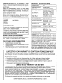
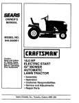
PRODUCT
CONGRATULATIONS
on your purchase of a Sears
Tractor, It has been designed, engineered and manufactured to give you the best possible dependability and
performance.
Should you experience any problem you cannot easily
remedy, please contact your nearest Sears Authorized
Service CentedDepartment
Department. We have competent, well-trained technicians and the proper tools to
service or repair this tractor.
Please read and retain this manual° The instructions will
enable you to assemble and maintain your tractor properly.
Always observe the "SAFETY RULES".
MODEL
NUMBER
917°258910
SERIAL
NUMBER
SPECnFICAT ONS
HORSEPOWER:
22.5
GASOLINE CAPACITY
AND TYPE:
3.5 GALLONS
UNLEADED REGULAR
OIL TYPE (API-SFiSG):
SAE 10W30 (above 32°F)
SAE 5W_30 (below 32°F)
OIL CAPACITY:
W/FILTER:
4.2 PINTS
W/O FILTER: 37 PINTS
SPARK PLUG:
(GAP: .030")
CHAMPION RC12YC
VALVE CLEARANCE:
NOT ADJUSTABLE
GROUND SPEED (MPH):
FORWARD:
REVERSE:
TiRE PRESSURE:
FRONT:
HEAR:
0 - 5.8
0-21
t4 PSI
t0 PSi
DATE OF PURCHASE
CHARGING SYSTEM:
15 AMPS @ 3600 RPM
THE MODELAND SERIAL NUMBERS WILL BE FOUND
ON A PLATE UNDER THE SEAT,
BATTERY:
YOU SHOULD RECORD BOTH SERIAL NUMBER AND
DATE OF PURCHASE AND KEEP !N A SAFE PLACE
FOR FUTURE REFERENCE.
AMP/HR:
MIN CCA:
CASE SIZE:
BLADE BOLT TORQUE:
30-35 FT_ LBS..
MAINTENANCE
CUSTOMER
WARNING:
This tractor is equipped with an internal
combustion engine and should not be used on or near any
unimproved forest-covered, brush-covered or grass-covered land unless the engine's exhaust system is equipped
with a spark arrester meeting applicable local or state laws
(if any),, If a spark arrester is used, it should be maintained
in effective working order by the operator°
AGREEMENT
A Sears Maintenance
Agreement
uct. Contact your nearest Sears
is available on this prodstore for details.
RESPONSIBILITHES
o
Read and observe
o
Followaregularscheduleinmaintaining,
using your tractor°
the safety
•
Follow the instructions
under "Customer Responsibili*
ties" and "Storage" sections of this owner's manual.
rules,
In the state of California the above is required by law
(Section 4442 of the California Public Resources Code),
Other states may have similar laws, Federal taws apply on
federal lands, A spa_rkarrester for the muffler is available
through your nearest Sears Authorized Service Center/
Department (See REPAIR PARTS section of this manual).
caringforand
LiMiTED TWO YEAR WARRANTY
35
280
U1R
ON CRAFTSMAN
RUDING EQUIPMENT
For two (2) years from the date of purchase, if this Craftsman Riding Equipment is maintained, lubricated and tuned up according
to the instructions in the owner's manual, Sears will repair or replace, free of charge, any parts found to be defective in material
or workmanship.
This Warranty does not cover."
•
,
•
•
Expendable items which become worn during norma! Use, such as blades, spark plugs, air cleaners, belts, etc.
Tire rep!acement or repair caused by punctures from outside objects, such as nails, thorns, stumps, or glass.
Repairs necessary because of operator abuse, negligence, improper storage or accident or the failure to maintain the
equipment according to the instructionscontained in the owner's manual
Riding equipment used for commercial or rentai purposes.
LIMITED 90 DAY WARRANTY
ON BATTERY
For ninety (90) days from date of purchase, if any battery included with this riding equipment proves defective in matedal or
workmanship and our testing determines the battery will not hold a charge, Sears wilt replace the battery at no charge
IN-HOME WARRANTY SERVICE ON YOUR CRAFTSMAN RIDING EQUIPMENT IS AVAILABLE AT NO-CHARGE FOR 30
DAYS FROM THE DATE OF PURCHASE.
PLEASE CONTACT YOUR NEAREST SERVICE CENTER. AFTER 30 DAYS
FROM THE DATE OF PURCHASE, WARRANTY SERVICE IS AVAILABLE BY TAKING YOUR CRAFTSMAN RIDING EQUIPMENT TO YOUR NEAREST SEARS SERVICE CENTER. (IN-HOME WARRANTY SERVICE WILL STILL BE AVAILABLE
AFTER 30 DAYS FROM THE DATE OF PURCHASE BUT A STANDARD TRiP CHARGE WILL APPLY) THIS WARRANTY
APPLIES ONLY WHILE THIS PRODUCT IS IN THE UNITED STATES.
This Warranty gives you specific legal rights, and you may also have other rights which may vary from state to state
SEARS,
ROEBUCK
AND CO., D/817 WA, HOFFMAN
3
ESTATES,
IL 60179
,,,
,,,,ll,, u.....
i,,,,
i i ,
i
r,,
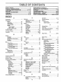
TABLE OF CONTENTS
SAFETY RULES ............................................................
2
PRODUCT SPECIFICATIONS ...................................... 3
CUSTOMER RESPONSIBILITIES ..................... 3, 16-19
WARRANTY ..................................................................
3
TRACTOR ACCESSORIES ..................................... 5,15
ASSEMBLY ..............................................................
7-10
OPERATION ...........................................................
12-16
MAINTENANCE
SCHEDULE
......................................
17
SERVICE AND ADJUSTMENTS
............................
21-27
STORAGE ...................................................................
28
TROUBLESHOOTING ............................................
29-30
REPAIR PARTS - TRACTOR .................................
32-50
REPAIR PARTS - ENGINE ....................................
51-58
PARTS ORDERING/SERVICE
................ BACK COVER
iNDEX
A
E
Operation .....................................................
12-16
Accessories .............................................. 5
Electrical:
lntedocks and Relays .................... 26
Schematic ..............................................
31
Wiring Diagram ............................. 32
Engine:
Air Filter ...............................................20
Air Screen ....................................... 19
Cooling Fins .......................................20
Oil Change ..................................... 19
Oil Level ........................................... t5
Oil Type .........................................15,t9
Preparation ........................................15
Repair Parts ............................. 51-58
Starting ...................................... 15-16
Storage .......................................... 28
Operating Mower ..................................... 14
Options:
Accessories
Spark Arrester ............................... 3,40
F
S
Filter:
Air Filter _.......................................... 20
Fuel .....................................................20
Oil ...................................................... 20
Fuel:
Storage .................................................
28
Type .......................................................
15
Fuse .................................................................
26
Safety Rules ............................................ 2
Seat .....................................................................
8
Adjustments:
Brake ........................................................
23
Carburetor, .............................................
27
Clutch Pulley ..............................................
23
Gauge Wheels ....................................
14
Mower
Front*To-Back .......................... 22
Side-To-Side ............................ 21
Throttle Control Cable .................. 27
Air Filter, Engine ................................... 20
Air Screen, Engine ............................... 19
Assembly ............................................. 7-10
B
Battery:
Charging ..............................................8
Cleaning .......................................
20
Stading with Weak Battery ............ 25
Storage ........................................
28
Terminals ............................................t9
Belt:
Motion Drive
Removal/Replacement
............. 24
Mower Drive
Removal/Replacement
............ 22
Mower Blade Drive
Removal/Replacement
................23
Blade:
Sharpening ........................................ 18
Replacement ................................ ; 18
Brake Adjustment .......................................23
C
Carburetor Adjustment ........................
Clutch Pulley .......................................
Controls, Tractor ..................................
27
23
12
Customer Responsibilities .............. 17-20
Engine:
Air Filter ..................................... 20
Air Screen ......................................19
Cooling Fins ......................................
20
Engine Oil ............................. I5,t9
Fuel Filter', .................................... 20
Spark Plug(s) ................................20
Tractor:
Battery ......................................
18
Blade ........................................
18
Lubrication Chart ....................... 17
Maintenance Schedule ............ 17
Tire Care .............................. 8,18,25
Transaxle ........................................t9
Cutting Height, Mower ..........................
t3
H
Headlights ...................................................
26
Hood Removal/installation
................... 26
L
Leveling Mower Deck ................................
22
Lubrication:
Chart ...................................................17
Engine ..................................................19
Maintenance Schedule ....................... 17
Mower:
Adjustment, Front-to-Back ........... 22
Adjustment, Side4o-Side .................21
Blade Replacement ..........................18
Blade Sharpening ......................... 18
Cutting Height ..........................................
13
Installation .................................... 21
Operation .....................................
14
Removal
21
Mowing Tips ........................................... I6
Muffler ..................................................
20
Spark Arrester ............................. 3,40
.........................................
O
Oil:
Cold Weather Conditions ..........15,t 9
Engine ..................................................
19
Storage ..............................................28
4
................................................
5
P
Parking Brake .......................................... 13
Pads Bag ..................................................... 6
Pads, Reptacemen_Repair ................
32-50
ProductSpecifications
................................3
R
Repair Pads .........................................32-50
Service and Adjustments .......................
21-27
Carburetor ......................................... 27
Clutch Pulley .....................................23
Fuse ................................................... 26
Hood Removalllnstallation
.............26
Motion Drive Belt
Removal/Replacement
...................
22
Mower Drive Belt
Removal/Replacement
...............22
Mower Blade Drive Belt
Removal/Replacement
............. 23
Mower Adjustment
Front-to-Back .....................................
22
Side-to-Side ............................... 21
Mower Removalllnstallation ......... 21
Tire Care .................................. 8,16,25
Slope Guide Sheet
59
Spark Plug(s) ....................................................
20
Specifications ..................................................
3
Starting the Engine ...............................
15-16
Steering Wheel .............................................
7,24
Stopping the Tractor ............................. 13
Storage
28
....................................
............................................................
T
Throttle Control Cable Adjustment ....... 27
Tires .......................................................
8,18,25
Troubleshooting Chad_,°:o .................29-30
Transaxte ....................................................19
W
Warranty ................................................
3
Wiring Diagram ...................................... 32
Wiring Schematic ................................ 31
..........
i,, ..........
,
............
,
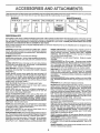
AND ATTAOHMEHT$
AOOI$SOI!IS
These accessories and attachments were available through most Sears retat outlets and service centers when the tractor was purchased.
Most Sears stores can order these items for you when you provide the model number of your tractor.
ENGINE
SPARK PLUG
MAINTENANCE
GAS CAN
ENGINE OIL
I FUEL STABILIZER
AIR FILTER
I
BLADES
BELTS
PERFOF{MANCE
Sears offers a wide variety of attachments that fityour tractor.
you. This Ist was current at the time of publication; however,
may be made in these attachments, or some may no longer
accessories
and attachments that are available for your
Most of these attachments
attaching and detaching.
Many of these are listed beIow with brief explanations of how they can help
it may change in future years - more attachments may be added, changes
be avalable or fit your model Contact your nearest Sears store for the
tractor+
do not require additional hitches or conversion
AERATOR promotes deep root growth for a healthy lawn, Tapered
2.5-inch steel spikes mounted on lO-inch diameter discs puncture
holes in soil at close intervals to let moisture soak in. Steel weight tray
for increased penetration
kits (those that de are indicated) and are designed for easy
SLEEVE CULTIVATOR is 43 inches wide_ Prepares ground for
seeding, helps weed control. Steel frame holds 5 adjustable sweeps,
Adjusts verlcaly, horizontally. (Requires sleeve hitch ) Optional
accessory:
steel furrow opener for wider openings for potatoes,
corn, and other deep-seeded crops.
BUMPER protects front end of tractor from damage
CARTS make hautng easy Variety of sizes available, plus accessories such as side panel kits, tool caddy, cart cover, protectivemat and
dolly°
CORING AERATOR lakes small plugs out of sol to allow moisture
and nutrients to reach grass roots° 36-inch swath. 24 hardened steel
coring tips. 150 lb capacity weight tray
DISC HARROW has 2 gangs of 4 steel blades that angle from !0 to
20 degrees, 40 inches w_de. Can hook2 units in tandem (Requires
sleeve hitch.)
SLEEVE HITCH for use with master lift system
uncouples,
Single pin couples/
SNOWTHROWER has 42-inch swath Drum-type auger handles
powde ryand wet!heavy snow Mounts easilywith simple pin arrangement. Discharge chute adjusts from tractor seat. 6-inch diameter
spout discharges snow 10 to 50 feet. Lift controled at tractor seat
(Use with chains and wheel weights and/or rear drawbar weightr)
SPRAYERS use 12-voff DC electric motor that connects to the tractor
battery or other 12-volt source° Includes booms for automatic
spraying end hand held wand for spot spraying Wand has adjustable
spray pattern. For applying herbicides, insecticides, fungicides and
fquid fertlizers
DOZER BLADE removes snow; grades dirt, sand and gravel. 4B
inches wide, t7 incheshigh, clears 44-inch path when angled. Master
lift control lever for operator ease_ Spring tdp for snow removal on
uneven pavement; built-in float for blade to follow ground contour,
Reversible, replaceable scraper bar. (Use with tire chains and wheel
weights and/or rear drawbar weight.)
EASY OIL DRAIN VALVE makes oil changes easier, faster.
FRONT NOSE ROLLER canters in front of mower deck to reduce
chances of "scalping" on uneven terrain,
GANG HITCH lets you tow 2 or 3 pu!l-behind attachments at
once, such as sweepers, dethatchers, aerators (not for use with
rolera, carts or other heavy attachments)
MULCH RAKFJDETHATCHER loosens soil and flips thatch and
matted leaves to lawn surface for easy pickup. Twenty spring tine
teeth Useful to prepare bare areas for seeding, Available fortront or
rear mounting. HIGH PERFORMANCE REEL-ACTION SPRING
TINE DETHATCH ER covers 36-inch wide path and tosses thatch into
large hopper Mounts behind tractor
PLOW turns soil 6 inches deep, cuts 10-inch furrow. Crank adjustment controls depth, 3-position yoke sets width, Heavy steel landside
Ior straight furrowing, (Requires sleeve hitch)
RAMP TOPS AND FEET let you load and unload tractor from a
pickup truck Use with 2 x B or 2 x 10 lumber.
SPREADEPJSEEDERS make seeding, fertilizing, and weed killing
easy, Broadcast spreaders are also useful for granular de-icers and
sand
SWEEPERS let you colect grass clppings and leaves°
TILLER has Bhp e ngine to prepare seed beds, cultivate, and compost
garden residue, Chain-drive transmission, Six 1t-inch diameter one
piece heat-treated steel tines. Tils 30-inch path. (Requires sleeve
hitch°) Or use 5 hp tow-behindTILLER with 36-inch swath to prepare
seed beds, cultivate and compost garden residue. Tiller has its own
buttqn lilt and depth control system and does NOT require a sleeve
hitch, Fits any lawn, yard or garden tractor, Simply hook up to the
tractor drawbar and go_ Optional accessories for 5 hp tillerconvert
unit for dethetching, aerating, hilling...without tools,
TIRE CHAINS are heavy duty; closely spaced extra-large cross links
give smooth ride, outstanding traction.
TRACTOR CAB has heavy duty vinyl fabric Over tubularsteel frame,
ABS plastic top; clear plastic windshield offers 360 degree visibility
Hinged metal doors with catch Keeps operator warm and dry.
Remove vinyl sides and windshields for use as sun protector in
summer. Optional accessories include:
tinted/tempered sold
safety glass windshield with hand operated wiper; 12wolt amber
caution light for mounting on cab top,
REAR GRADER BLADE is 42 incheswide and operated from ddver's
seat. Reversible steel blade can be angled at 30 degrees for grading.
Reverses for pushing snow backwards. (Requires sleeve hitch )
ROLLER for smoother lawn surface. 36-inch wide, 18-inch diameter
water-tight drum holds up to 390 lbs, of weight. Rounded edges
prevent harm to turf. Adjustable scraper automaticallycleans drum.
VACS for powerful collection of heavy grass clippings and leaves.
Optional wand attachmentto pick up debris in hard-to-reach places.
VAC/CHIPPER includes a chipper-shredder.
WEIGHT BRACKET for drawbarfor snow removal applications. Can
be mounted on front of traelor for ptowing applications Uses (1) 55
Ib, weight
WHEEL WEIGHTS for rear wheels provide needed traction for snow
removal or dozing heavy materials
5
i, ,111
...........
Parts Bag contents
shown
m
(4) Washers 3/8 x 3/4 x 14 Ga_
(4) Retainer Springs
(4) Bracket_
_ [z
(doubletoop_
_
. , Bolts .
f'_
(4) Clevis Pins
_
_ (4) Adjusting Bar
gi
(4) Shoulder Bolt
(12) CrownLock Nuts 3/16 x 8
(4) Loeknut
IIIt I ('?1
_\
(4) Wheels
3/8-18
.....................
i
(1) shoulder' Bolt
5/16-18
----1
Steering
Wheel
(1) Knob
Manual
i
Steering
Sleeve
Cassette
Video
Parts bag contents
(1) Washer 17/32 x 1-3/16 x 12 Gauge
I_L
,
Seat
Parts Bag
not shown full size
_rq_._.
•
u,
(2) Front Link Assemblies
iner Springs (single loop)
_
(2) Keys
_
(__
bJ
Insert
Steedng
Wheel
"_ .......................
ii,
in,
n,nl_
_,I
i, i
(2) Hex Bolts 1/4-20 x 314
(2) Hex Nutsj¢:_,
1t4-20
(2) Washers
_
9/32 x 5/8 x 16 Ga, "_"
...............
ii,u,i i,nl,,
(2) Lock
Washers
Slope Sheet
1/4
,nnl ii,i ..............
6
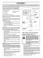
ASSEMBLY
Your new tractor has been assembled at the factory with the exception of those parts left unassembled for shipping purpose&
To ensure safe and proper operation of your tractor all parts and hardware you assemble must be tightened securely° Use
the correct tools as necessary to insure proper tightness,,
TOOLS
REQUIRED
FOR ASSEMBLY
STEERING
WHEEL INSERT
A socket wrench set will make assembly easier, Standard
wrench sizes are listed,.
(2) 7/16" wrenches
Tire pressure gauge
(1) I/2" wrench
Utility knife
__.
HEX BOLT
- LOCI( WASHER
(1) 9/16" wrench
(1) 3/4" socket with drive ratchet
When right or left hand is mentioned in this manual, it
means when you are in the operating position (seated
behind the steering wheel).
TO REMOVE TRACTOR
FROM CARTON
_
UNPACK
Remove all accessible loose parts and parts cartons
from carton (See page 6).
STEERING
WHEEL
•
Cut, from top to bottom, along lines on all four corners
of carton, and lay panels flaL
ADAPTER
.
Check for any additional
remove.
.
WHEEL
CARTON
STEERING
SHAFT
/
.S"
loose parts or cartons and
/
"2
<
.'
/
!/
BEFORE ROLUNG TRACTOR OFF SKID
ATTACH
STEERING
WHEEL
k
I
STEERING/
SLEEVE /
I
L
_l
/
t
i
// /
/
/
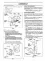
(See Fig. 1)
°
Remove hex bolt, lock washer and large fiat washer
from steering shaft.
•
Position front wheels of the tractor so they are pointing
straight forward°
HOW TO SET UP YOUR TRACTOR
-
Slide steering sleeve over steering shaft.
CONNECT
.
Position steering wheel so cross bars are horizontal
(left to right) and slide onto steering wheel adapter.
-
Secure steering wheel to steering shaft with hex bolt,
lock washer and large flat washer previously removed.
Tighten securely,
o
Snap steering wheel insert into center of steering
wheel.
Remove protective materials from tractor hood and
grill
IMPORTANT: CHECK FOR AND REMOVE ANY STAPLES
IN SKID THAT MAY PUNCTURE TIRES WHERE TRACTOR
IS TO ROLL OFF SKIDo
FIG. 1
,
BATTERY
, ,, ,.,,,,,,,
(See Fig, 2)
_
r
nals by allowing a wrench or any other
object
to contact
terminals
at the
CAUTION;
Do not both
short
battery termisame time, Before connecting battery,
remove metal bracelets, wristwatch
bands, rings, etc,
Positive terminal must be connected
first to prevent sparking from accidental grounding.
-
•
Lift hood to raised position.
°
Open terminal access doors, remove terminal protective caps and discard.
°
If this battery is put into service after month and year
indicated on label (label located between terminals)
charge battery for minimum of one hour at 6-10 amps.
°
o
°
Place freewheel control in freewheeling position to
disengage transmission (See 'q'O TRANSPORT" in
the Operation section of this manual).
Roll tractor forward off skid.
First connect RED battery cable to positive (+) battery
terminal with hex bolt, flat washer, lock washer and hex
nut as shown_ Tighten securely°
°
o
Remove mower and packing materials.
Remove ties from V-belts,
•
Connect BLACK grounding cable to negative (-) battery terminal with remaining hex bolt, flat washer, lock
washer and hex nut. Tighten securely.
Close terminal access doors..
TO ROLLTRACTOR
section for location
OFF SKID (See Operation
and function of controls)
°
Press lift lever plunger and raise attachment lift lever to
its highest position.
•
Release parking brake by depressing
pedal,
•
clutch/brake
ASSEMBLY
ii
i
n,,u
i.,!_l
m
........
Use terminal access door's for':
Inspection
CHECK TERE PRESSURE
for secure connections
(to tighten hard-
o
Inspection for corrosion.
The tires on your tractor' were overinflated at the factory for
shipping purposes. Correct tire pressure is important for
best cutting performance.
.
Testing battery.
o
o
Jumping (if required).
o
Periodic charging.
ware),
DISCARD
CHECK
HEX NUT
PROTECTIVE
CAPS
TERMINAL
Reduce tire pressure to PSI shown in "PRODUCT
SPECIFICATIONS" on page 3 of this manual.
FLAT
WASHER
LOCK
x
SYSTEM
After you learn how to operate your tractor', check to see
that the brake is properly adjusted. See 'q'o ADJUST
BRAKE" in the Service and Adjustments section of this
manual,
HEX
BOLT
WASHER
BRAKE
ASSEMBLE GAUGE WHEELS AND BRACKETS TO MOWER DECK (See Fig. 4)
TERMINAL
,°""
ACCESS
;
DOOR
,,-'
The gauge wheels are designed to keep the mower deck in
proper position when operating mower. Be sure they are
properly adjusted to ensure optimum mower performance.
•
Attach front gauge wheel brackets marked front left
(FL), front right (FR) to mower' deck using (3) carriage
botts and (3) locknut& For ease of installation do not
tighten Iocknuts until all carriage bolts have been
installed.
°
Attach rear gauge wheel brackets marked rear left (R
L), rear right (RR) to mower deck using (3) carriage
bolts and (3) Iocknuts. For ease of installation do not
tighten locknuts until all carriage bolts have been
installed,.
o
Slide gauge wheel bar down into bracket channel, Be
sure that gauge wheel bar aligning holes are on top.
Assemble gauge wheels as shown using shoulder
bolts, 3/8 washers and 3/8-16 center' tocknuts and
tighten securely.
•
Adjust gauge wheels to highest position for ease of
mower deck assembly,,
o Adjust gauge wheels before operating mower as shown
in the operation section of this manual
POSITIVE
(RED)
CABLE
NEGATIVE
(BLACK)
CABLE
FIG. 2
INSTALL
SEAT (See Fig. 3)
Adjust seat before tightening adjustment knob_
o
Remove cardboard
o
Place seat on seat pan and assemble shoulder bolt
packing on seat pan.
•
Assemble adjustment
Do not tighten,
,
Tighten shoulder bolt securely,
o
°
Lower seat into operating position and sit on seat.
Slide seat until a comfortable position is reached which
allows you to press clutch/brake pedal all the way
down.,
knob and flat washer loosely,
•
Get off seat without moving its adjusted position,
o
Raise seat and tighten adjustment knob securely.
RETAINDER
PiN
"\
CROWNLOCK
NUT
""_'-_SPRING\
SEAT
BRACKET
SEAT PAN
SHOULDER
BOLT
SHOULDER
BOLT
\
ADJUSTING
BAR
WHEEL
,_3/8 WASHER
FLAT WASHER
ADJUSTMENT
KNOB
"*'_-._
CAR RIAG E
_
BOLTS
318-I6 CENTER
LOCKNUT
FIG. 4
FIG. 3
8
,,
u,
, u,,,i.u ............
i,,r...............
i¸
ASSEMBLY
.........................
i,,,
,.............
,_
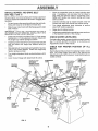
INSTALL MOWER
AND DRIVE BELT
(See Figs. 5 and 7)
o
Place the suspension
arms on inward pointing deck
pins, If necessary, rock and raise front of mower to
atign deck pins with the holes in suspension arms,
Retain with double loop retainer springs with loops
down as shown,,
Be sure tractor is on level surface and mower suspension
arms are raised with attachment lift control. Engage parking brake,
•
Cut and remove ties securing anti-sway bar and belts,
o
Connect anti-sway bar to chassis bracket under left
footrest and retain with doubte loop retainer spring,
Swing antFsway bar to left side of mower deck,,
Stide mower under tractorwith discharge guard to right
side of tractor,
o
Turn height adjustment knob clockwise
stack from mower suspension_
Raise deck to highest position,
IMPORTANT:
CHECK GROOVES,
BELT FOR PROPER
iN
ALL MOWER PULLEY
INSTALLROUTING
BELT INTO
ELECTRIC CLUTCH PULLEY GROOVE
=
,,
Install one front link in top hole of the LH. front mower
bracket and L,Hofront suspension bracket. Retain with
two single loop retainer springs as shown.
CHECK MOWER LEVELNESS
o
Install second front link in R.Hofront suspension bracket
only and retain with single loop retainer spring as
shown.
•
Slide right side of mower back and instaltlink in top hole
of R.H. front mower bracket. Retain with single loop
retainer spring as shown,
•
°
Turn height adjustment knob counterclockwise
stops,
until it
.
Lower mower linkage with attachment lift control.
o
to remove
Adjustgaugewheelsbeforeoperatingmowerasshown
in the Operation section of this manual.
For best cutting results, mower should be properly leveled.
See "TO LEVEL MOWER HOUSING" in the Service and
Adjustments section of this manual
CHECK
BELTS
FOR
PROPER
POSiTiON
OF
ALL
See the figures that are shown for replacing motion, mower
drive, and mower blade drive belts in the Service and
Adjustments section of this manual. Verify that the belts are
routed correctly.
FRONT
DOUBLE LOOP
RETAINER
SPRING (Outward
pointing deck pins)
CHASSIS
SUSPENSION
ARMS
BRACKETS
FRONT
MOWER
BRACKET
FRONT
ELECTRIC
CLUTCH
PULLEY
SINGLE LOOP
RETAINER
SPRINGS
GAUGE
WHEEL
/
ANTI-SWAY
BAR
DISCHARGE
GUARD
DOUBLE
LOOP
RETAINER
SPRING
IDLER
PULLEY
FIG, 5
i ¸
i
,
,
1,1,,i
iI,,i
....
i,,,i,,,,,,,,,11,,,i,,,11,,,,11.,11
.......
ASSEMBLY
, ,,,
I .........
,, i,, ,,,111,1,,,,i,, ,i,i]111......................
,/CHECKLIST
BEFORE YOU OPERATE AND ENJOY YOUR NEW
TRACTOR, WE WISH TO ASSURE THAT YOU RECEIVE
THE BEST PERFORMANCE AND SA TISFA CTION FROM
THIS QUALITY PRODUCT_
PLEASE REVIEW THE FOLLOWING
CHECKLIST:
v"
All assembly instructions have been completed.
¢"
No remaining loose parts in carton,
¢"
Batteryis properly prepared and charged,
1 hour at 6 arnps)o
v"
Seat is adjusted comfortably and tightened securely.
v'
All tires are properly inflated. (For shipping purposes,
the tires were ovennfiated at the factory),.
,/
Be sure mower deck is properly leveled side-to-side/
front-to-rear for' best cutting results, (Tires must be
properly inflated for' leveling),
,/
Check mower and ddve belts. Be sure they are routed
properly around pulleys and inside all belt keepers_
,/
Check wiring. See that all connections are still secure
and wires are properly clamped,
(Minimum
v"
Before driving tractor, be sure freewheel control is in
drive position.
WHILE LEARNING HOWTO USE YOUR TRACTOR, PAY
EXTRA A TTENTION TO THE FOLLOWING IMPORTANT
ITEMS:
v'
,/
,,"
Engine oil is at proper level.
Fuel tank is filled with fresh, clean, regular unleaded
gasoline,
Become familiar with all controls _ their"location and
function° Operate them before you start the engine,
v"
Be sure brake system is in safe operating condition,
,/
It is important to purge the transmission before operating your tractor' for the first time. Follow proper starting
and transmission purging instructions (See "TO START
ENGINE" and "PURGE TRANSMISSION" in the Operation section of this manual),
1.0
i .....
L,_I_I
OPERATmON
These
symbols may appear
on your tractor or in literature supplied with the product.
Learn and understand
their meaning.
÷
BATTERY
CAUTION OR
WARNING
REVERSE
FORWARD
FAST
SLOW
ENGINE ON
ENGINE OFF
OIL PRESSURE
CLUTCH
LIGHTS ON
LIGHTS OFF
FUEL
CHOKE
MOWER HEIGHT
DIFFERENTIAL
LOCK
PARKING BRAKE
LOCKED
UNLOCKED
L
REVERSE
NEUTRAL
HIGH
LOW
PARKING BRAKE
÷
MOWER LIFT
ATTACHMENT
CLUTCH ENGAGED
IGNITION
ATTACHMENT
CLUTCH DISENGAGED
HYDROSTATIC
DANGER, KEEP HANDS AND FEET AWAY
FREE WHEEL
(Hydro Models only)
11
OPERATION
KNOW YOUR TRACTOR
READ
THiS
OWNER'S
MANUAL
AND
SAFETY
RULES
BEFORE
OPERATING
YOUR
TRACTOR.
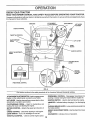
Compare the iitustrations with your tractor to familiarize yourself with the location of various controls and adjustments° Save
this manual for future reference°
AMMETER
ATTACHM ENT
CLUTCH SWITCH
LIGHT SWITCH
LIFT LEVER
_ _
PLUNGER
CHOKECONTROL
THROTTLE
CONTROL
CLUTCWBRAKE
PEDAL
LIFT LEVER
HOUR
METER
IGNITION SWITCH
HEIGHTADJUSTMENT
KNOB
PARKING BRAKE
LEVER
MOTION
CONTROL
LEVER
APPROX.
SPEEDS:
3
FREE WHEEL CONTROL
FIG. 6
Our tractors conform to the safety standards of the American National Standards Institute.
ATTACHMENT CLUTCH SWITCH- Used to engage mower
blades or other attachments mounted to your tractor,
FREEWHEEL CONTROL - Disengages transmission for
pushing or slowly towing the tractor with the engine off.
LIFT LEVER- Used to raise and lower mower deck or other
attachments mounted to your tracton
CLUTCH/BRAKE
PEDAL - Used for declutching and
braking the tractor and starting the engine.
IGNITION SWITCH - Used to start and stop the engine,
AMMETER - indicates battery charging (+) or discharging
PARKING BRAKE LEVER - Locks clutch/brake pedal into
the brake position_
MOTION CONTROL - Selects the speed and direction of
tractor.
CHOKE CONTROL - Used when starting a cold engine.
LIGHT SWITCH - Turns the headlights on and off.
THRO"n'LE CONTROL - Used to control engine speed,
HEIGHT ADJUSTMENT KNOB- Used to adjust the mower
height,
HOURMETER
12
_ Indicates hours of operation.
OPERATION
I
_
T"e operation of any tractor can result in foreign objects throt_n into the eyes, which canresult
_
in severe eye damage. Always wear safety glasses or eye shields while operating your tractor
or performing any adjustments or repairs. We recommend a wide vision safety mask over the
1
spectacles or standard safety glasses.
HOW TO USE YOUR TRACTOR
NOTE: Under certain conditions when unit is standing idle
with the engine running, hot engine exhaust gases may
cause "browning" of grass. To eliminate this possibility,
atways stop engine when stopping tractor on grass areas,
TO SET PARKING BRAKE (See Fig. 7)
Your tractor is equipped with an operator presence sensing
switch. When engine is running, any attempt by the
operator to leave the seat without first setting the parking
brake will shut off the engine_
°
Depress clutch/brake pedal into fult "BRAKE" position
and hold.
o
Place parking brake lever in "ENGAGED" position and
release pressu re from clutch/brake pedal° Pedal should
remain in "BRAKE" position. Make sure parking brake
will hold tractor secure.
PUSH IN TO
THROTTLE
"DISENGAGE"
CONTROL LEVER
ATTACHMENT
!
_
_.,_
| _
_
CAUTION:
Always stop tractor con_pletely, as described above, before teaw
ing the operator's
position;
grass catcher, etc.
TO USE CHOKE
CONTROL
to emp';:y
(See Fig, 7}
Use choke control whenever you are starting a cold engine.
Do not use to start a warm engine.
o To engage choke control, pull knob out Slowly push
knob in to disengage.
CLUTCH
SWITCH PULL OUT TO
TO USE THROTTLE
CHOKE
CONTROL
CONTROL
(See Fig. 7)
Always operate engine at full throttle.
o
Operating engine at less than full throttle reduces the
battery charging rate.
Full throttle offers the best mower performance,
CLUTCH/BRAKE
PEDAL"BRAKE"
POSITION
TO MOVE FORWARD
IGNITION
AND BACKWARD
(See Fig. 7)
The direction and speed of movement is controlled by the
motion control fever_
MOTION
CONTROL
LEVER
"DRIVE"
POSITION
HEIGHT
ADJUSTMENT
KNOB
\
"DISENGAGED
POSITION
....
PARKING
BRAKE
ENGAGED"
POSITION
NOTE:
Failure to move throttle control to slow (,_)
position and allowing engine to idle before stopping may
cause engine to "backfire"_
Never use choke to stop engine.
,
Slowly move motion control lever to desired position.
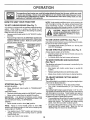
Turn knob clockwise ((-_) to raise cutting heighL
Turn knob counterclockwise (IF_)to
lower cutting
height.
The cutting height range is approximately 1-1/4" to 4-1/2'L
The heights are measured from the ground to the blade tip
with the engine not running. These heights are approximate and may vary depending upon soil conditions, height
of grass and types of grass being mowed.
o The average lawn should be cut to approximately 2-1/2
inches during the cool season and to over 3 inches
during hot months. For healthier and better looking
lawns, mow often and after moderate growth,
°
For best cutting performance, grass over 6 inches in
height should be mowed twice. Make the first cut
relatively high; the second to desired height.
Move throttle control to slow (,_,) position_
°
Release parking brake and clutch/brake pedal
•
o
MOWER BLADES
•
Move attachment clutch switch to "DISENGAGED"
position,
GROUND DRIVE
°
Depress clutch/brake pedal into full "BRAKE" position_
o Move motion control lever to neutral (N) position.
IMPORTANT;
THE MOTION CONTROL LEVER DOES
NOT RETURN TO NEUTRAL (N) POSITION WHEN THE
CLUTCH/BRAKE PEDAL IS DEPRESSED.
ENGINE -
Turn ignition key to "OFF" position and remove key.
Always remove key when leaving tractor to prevent
unauthorized use°
o
The cutting height is controlled by turning the height adjustment knob indesired direction_
STOPPING (See Fig. 7)
•
Start tractor with motion control lever in neutral (N)
position.
TO ADJUST MOWER CUTTING HEIGHT
(See Fig. 7)
FIG. 7
•
•
13
TO OPERATE
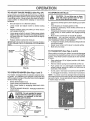
TO ADJUST GAUGE WHEELS (See Fig. 8A)
Gauge wheels are properly adjusted when they are slightly
offthe ground when mower is at the desired cutting height
in operating position. Gauge wheels then keep the deck in
proper position to help prevent scalping in most terrain
conditions.
"_C-AuTIO---'N:Do not drive
Be sure tractor' is on a flat levet surface.
•
Lower mower' and adjust mower to desired cutting
height.
o
Remove retainer spr!ng and clevis pin which secure
each gauge wheat bar,
•
Lower gauge wheels to ground= Raise gauge wheels
slightly to align holes in bracket and gauge wheel bar
and insert clevis pin° Gauge wheels should be slightly
off the ground.
up or down'_
hills with slopes greater than 15 ° and
do not drive across any slope
•
•
ON HILLS
I
I
Choose the slowest speed before starting up or down
hills.
°
o
Avoid stopping or changing speed on hills.
If slowing is necessary, move throttfe control lever' to
_lower position.
=
If stopping is absolutely necessary, push clutch/brake
pedal quickly to brake position and engage parking
brake_
o
Move motion control lever to neutral (N) position.
IMPORTANT:
THE MOTLON CONTROL LEVER DOES
NOT RETURN TO NEUTRAL (N) POSITION WHEN THE
CLUTCH/BRAKE PEDAL IS DEPRESSED.
To restart movement, slowly release parking brake and
clutch/brake pedal
o Slowly move motion control lever to slowest setting.
=
Make all turns slowly_
•
Rap{ace retainer spring into clevis pin.
IMPORTANT: BE SURE TO READJUST GAUGE WHEELS
IF YOU CHANGE THE CUTTING HEIGHT OFTHE MOWER
DECK.
RETAINER
SPRING
TO TRANSPORT
(See Figs. 6 and 9)
When pushing ortowing your tractor, be sure to disengage
transmission by placing freewheel control in freewheeling
position_ Free wheel control is located atthe rear drawbar
of tractor.
CLEVIS PIN
=
Raise attachment
ment lift control
°
•
Remove retainer spring from freewheel control rod
Push control rod in to disengage transmission and
reinsert retainer spring into control rod hole now on
back side of the brackeL
•
°
Do not push or' tow tractor at more than two (2) MPH.
To reengage transmission, reverse above procedure°
FIG. 8A
TO OPERATE
MOWER
(See Figs. 6 and 7)
Your tractor is equipped with an operator presence sensing switch, Any attempt by the operator to leave the seat
With the engine running and the attachment clutch engaged
witl shut off the engine.
,
•
•
lift to highest position with attach-
NOTE: To protect hood from damage when transporting
your tractor on a truck or a trailer, be sure hood is closed and
secured to tractor. Use an appropriate means of tying hood
to tractor (rope, cord, etc)_
Select desired height of cut.
Lower mower with attachment lift control
Start mower blades by engaging attachment clutch
control.
TO STOP MOWER BLADES - disengage attachment
clutch control=
CAUTION: Do not operate the mower
without either the entire grass catcher,
on mowers so equipped, or the discharge guard in place,
....
i
I
i
!
R_H.
RUNNER
FIG. 9
DISCHARGE
GUARD
FIG. 8B
14
OPERATRON
BEFORE
CHECK
STARTWNG THE ENGBNE
ENGINE
TO START
The engine in your tractor has been shipped, from the
factory, already filled with summer weight oil.
•
Check engine oil with tractor on level ground°
•
Unthread and remove oii fill cap/dipstick; wipe oil off°
Reinsert the dipstick into the tube and rest oil fill cap on
the tube. Do not thread the cap onto the tube. Remove
and read oil level If necessary, add oil until "FULL"
mark on dipstick is reached Do not overfill,
•
For cold weather operation you should change oil for
easier starting (See "OIL VISCOSITY CHART" in the
Customer Responsibilities section of this manual)_
-
To change engine oil, seethe Customer Responsibilities section in this manual.
o
o
o
.
o
Sit on seat in operating position, depress clutch/brake
pedal and set parking brake,
Place motion control lever in neutral (N) position.
Move attachment clutch to "DISENGAGED" position°
Move throttle control to fast (=_) position
Pull choke control out for a cold engine start attempt,
For a warm engine start attempt the choke control may
not be needed.
Note: Before starting, read the warm and cold starting
procedures below.
•
Insert key into ignition and turn key clockwise to"START"
position and release key as soon as engine starts Do
not run starter continuously for more than fifteen seconds per minute. If the engine does not start after
several attempts, push choke control in, wait a few
minutes and try again. If engine still does not start, pull
the choke control out and retry°
WARM WEATHER STARTING (50 ° F and above)
•
When engine starts, slowly push choke control in until
the engine begins to run smoothly, if the engine starts
to run roughly, pull the choke control out slightly for a
few seconds and then continue to push the control in
slowly°
•
The attachments and ground drive can now be used.. If
the engine does not accept the load, restart the engine
and allow it to warm up for one minute using the choke
as described above.
FIG. 10
ADD GASOLINE
o
Fill fuel tank.
Use fresh, clean, regular unleaded
gasoline with a minimum of 87 octane. (Use of leaded
gasoline will increase carbon and lead oxide deposits
and reduce valve life). Do not mix oil with gasoline.
Purchase fuel in quantities that can be used within 30
clays to assure fuel freshness.
IMPORTANT: WHEN OPERATING IN TEMPERATURES
BELOW 32°F(0°C), USE FRESH, CLEAN WINTER GRADE
GASOLINE TO HELP INSURE GOOD COLD WEATHER
STARTING,
COLD WEATHER STARTING (50 ° F and below)
•
When engine starts, slowly push choke control in until
the engine begins to run smoothly° Continue to push
the choke control in small steps allowing the engine to
accept small changes in speed and load, until the
choke control is fully in. If the engine starts to run
roughly, pull the choke control out slightly for a few
seconds and then continue to push the control in
slowly. This may require an engine warm-up period
from several seconds to several minutes, depending
on the temperature..
HYDROSTATIC TRANSMISSION WARM UP
WARNING:
Experience indicates that alcohol blended
fuels (called gasohol or using ethanol or methanol) can
attract moisture which leads to separation and formation of
acids during storage° Acidic gas can damage the fuel
system of an engine while in storage, To avoid engine
problems, the fuel system should be emptied before storage of 30 days or longer. Drain the gas tank, start the
engine and let it run until the fuel lines and carburetor are
empty. Use fresh fuel next season. See Storage Instructions for additional information,
Never use engine or
carburetor cleaner products in the fuel tank or permanent
damage may occur.
I&
(See Fig, 6)
When starting the engine for the first time or if the engine
has run out of fuel, it will take extra cranking time to move
fuel from the tank to the engine,
•
Be sure freewheel control is in the transmission engaged position.
OIL LEVEL (See Fig. 10)
•
ENGINE
°
Before driving the unit in cold weather, the transmission should be warmed up as follows:
.
Be sure the tractor is on level ground.
•
Place the motion control lever in neutral
Release the parking brake and let the clutch/brake
slowly return to operating position.
• Allow one minute for transmission to warm up.
This can be done during the engine warm up
period.
.
The attachments can be used during the engine warmup period after the transmission has been warmed up
and may require the choke control be pulled out slightly.
NOTE: If at a high altitude (above 3000 feet) or in cold
temperatures (below 32 F) the carburetor fuel mixture may
need to be adjusted for best engine performance. See "TO
ADJUST CARBURETOR" in the Service and Adjustments
section of this manual
filler neck. Do not overfill Wipeoff any
spilled oil or fuel. Do not store, spill or
AUTION:
to an
bottom
gas tank
use
gasoline Fill
near
open of
flame.
15
OPERATION
PURGE
1-'_'_
MOWBNG TgPS
TRANSMgSSION
freewheel lever while the engine is run,
CAUTi'ON:
Never engage or disengage
rang
I
,
=
Tire chains cannot be used when the mower housing is
attached to tractor.
,
Mower' should be properly leveled for best rnow!ng
performance. See '%0 LEVEL MOWER HOUSING in
the Service and Adjustments section of this manual
Use the runner on the right hand side of mower as a
guide. The blade cuts approximately an inch outside
the runner (See Fig. 8),
The left hand side of mower should be used for trimming.
Drive so that clippings are discharged onto the area
that has been cut. Have the cut area to the right of the
tractor. This wit! result in a more even distribution of
clippings and more uniform cutting.
When mowing large areas, start by turning to the dght
so that clippings will discharge away from shrubs,
fences, driveways, etc. After one or' two rounds, mow
in the opposite direction making left hand turns until
finished (See Fig. 11).
if grass is extremety tall, it should be mowed twice to
reduce load and possible fire hazard from dried clippings. Make first cut relatively high; the second to the
desired height.
Do not mow grass when it is wet= Wet grass will plug
mower and leave undesirable clumps. Allow grass to
dry before mowing=
Always operate engine at full throttle when mowing to
assure better mowing performance and proper discharge of material. Regulate ground speed by selecting a low enough gear to give the mower cutting
performance as well as the quality of cut desired=
When operating attachments, setect a ground speed
that will suit the terrain and give best performance of
the attachment being used.
To ensure proper operation and performance, it is recommended that the transmission be purged before operating
tractor for' the first time. This procedure will remove any
trapped air inside the transmission which may have developed during shipping of your tractor.
IMPORTANT: SHOULD YOUR TRANSMISSION REQUIRE
REMOVAL FOR SERVICE OR REPLACEMENT,
IT
SHOULD BE PURGED AFTER REINSTALLATION
BEFORE OPERATING THE TRACTOR.
.
.
Place tractor safely on level surface with engine off and
parking brake set.
=
•
Disengage transmission by placing freewheel control
in freewheeling position (See 'q-O TRANSPORT" in
this section of manual).
o
Sitting in the tractor seat, start engine° Afterthe engine
is running, move throttle control to slow (,_) position.
With motion control lever in neutral (N) position, slowly
disengage clutch/brake pedal.
o
Move motion control lever to full forward position and
hold for' five (5) seconds. Move lever to full reverse
position and hold for five (5) seconds. Repeat this
procedure three (3) times
o
o
=
°
•
NOTE: During this procedure there will be no movement of
drive wheeis. The air is being removed from hydraulic drive
systerno
•
Move motioncontrotleverto
neutral (N) position. Shutoff engine and set parking brake.
=
Engage transmission by placing freewheel control in
driving position (See "TO TRANSPORT" in this section
of manual)_
°
Sittinginthetractor seat, start engine. Aftertheengine
is running, move throttle control to half (1/2) speed.
With motion control lever in neutral (N) position, slowly
disengage clutch/brake pedal.
o
Slowly move motion control lever forward, after the
tractor' moves approximately five (5) feet, slowly move
motion control lever to reverse position. After the
tractor moves approximately five (5) feet return the
motion control lever to the neutral (N) position. Repeat
this procedure with the motion control lever three (3)
times.
o
o
r
FiG. 11
Your' tractor is now purged and now ready for normal
operation.
16
CUSTOMER
RESPONS!!BQL TIES
F,
LL,NOATES
ASYOU
COMPLETE
..........
;On
r
Check Brake Operation
_
Check Tire Pressure
_
Check for Loose Fasteners
!R
Sharpe'rdRePia'ce
iC
iT
Lubrication Chart
Check Battery LeveVRecharge
i0
Clean Battery and Termlnais
IR
Cheek Transax'le Cooling
LA
Mowe;
v',
_'
Bi'ades .............
e"
6/'4
e,'
_.....
[
1
_4#
J
,,
,
......
Adjust Blade Belt(s) Tension
Adjust Motion Drive Belt(s) Tension
.......
,,,,
Check
Engine Oit Level
Change Engine
E
6/
v'
Oil
!_/2i .....
Clean Air Fiiter
N
CleanA
G
Inspect Muffter/SparkArrester
Screen
Cooling
Fins
= Clean
eplaceEngine
Oft F!lter
(If equipped)
Replace
Spark Plug
Replace
Air Fitter Paper"Cartridge
Replace
Fuel Filter
I
1 - Change more often when operating under a heavy load or in hlgh ambient temperatures
2 - Service more or|an when opers_ing in dirty or dus|y conditions
3 - If equipped with oil Jilter, change oil every 50 hours
4 - Replace blades more often when mowfeg in sandy eo_I
GENERAL
5 * I! equippedw}thadjuslable system
6 _No! requiredif equipped with maintenance4_'eebattery
7 -Tighlea _ron|axle pivol bo|l !.o3,5ft -Ibs maximum
Do no!overtighten
RECOMMENDATIONS
The warranty on this tractor does not cover items that have
been subjected to operator abuse or negligence,, To
receive full value from the warranty, operator must maintain
tractor as instructed in this manual.
Some adjustments will need to be made periodically to
properly maintain your tractor.
LUBRICATION
(_)TIE
CHART
ROD BALL JOINTS
®
®
®
FRONT
BEARING
BEARING
ZERK
ZERK
All adjustments in the Service and Adjustments section of
this manual should be checked at least once each season,
,
Once a year you should replace the spark plug, clean
or replace air filter, and check blades and belts for
wear. A new spark plug and clean air filter assure
proper air-fuel mixture and help your engine run better
and last longer,,
BEFORE
EACH
®STEERING
SECTOR GEAR
TEETH
ENGINE ®
USE
•
Check engine oil level.
•
Check brake operation.
•
°
Check tire pressure.
Check for loose fasteners,
L
(_) SPRAY SILICONE
IMPORTANT;
DO NOT OIL OR GREASE THE PIVOT POINTS
WHICH HAVE SPECIAL NYLON BEARINGS
VISCOUS LUBRICANTS WILL ATTRACT
DUST AND DIRT THAT WILL SHORTEN
THE LIFE OF THE SELF-LUBRICATING
BEARINGS,
tF YOU
FEEL THEY MUST BE LUBRICATED,
USE ONLY A DRY, POWDERED GRAPHITE
TYPE LUBRICANT
SPARINGLY
®
GENERAL
LUBRICANT
PURPOSE GREASE
_) REFER TO CUSTOMER
'17
(MOVE BOOTS TO LUBRICATE)
RESPONSIBILITIES
"ENGINE"
SECTION
CUSTOM
ESPONS B!L
E$
TRACTOR
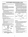
TO SHARPEN
Always observe safety rules when performing any maintenanceo
Care should be taken to keep the blade balanced. An
unbalanced blade will cause excessive vibration and eventual damage to mower and engine.
BRAKE
OPERATION
If tractor requires more than six (6) feet stopping distance
at high speed in highest gear, then brake must be adjusted°
(See "TO ADJUST BRAKE" in the Service and Adjustments section of this manual)°
BLADE
(See Fig. 13)
o
The blade can be sharpened with a file or on a grinding
wheel. Do not attempt to sharpen while on the mower.
o
To check blade balance, you will need a 5/8" diameter
steel bolt, pin, oracone baIancer. (When using acone
. balancer, follow the instructions supplied with balanGer)°
TIRES
o
Maintain proper air pressure in all tires (See "PRODUCT SPECIFICATIONS" on page 3 of this manual),
•
=
Keep tires free of gasoline, oil, or insect control chemicals which can harm rubber.
Slide blade on to an unthreaded portion of the steel bolt
or pin and hold the bolt or pin parallel with the ground.
If blade is balanced, it should remain in a horizontal
position. If either end of the blade moves downward,
sharpen the heavy end until the blade is balanced.
°
Avoid stumps, stones, deep ruts, sharp objects and
other hazards that may cause tire damage.
NOTE: Do not use a nail for balancing blade_ The [obes of
the center hole may appear' to be centered, but are not.
NOTE: To seal tire punctures and prevent flat tires due to
slow leaks, tire sealant may be purchased from your local
parts dealer. Tire sealant also prevents tire dry rot and
corrosion.
BLADE
CENTER HOLE
/)/
5/8" BOLT_\_
CARE
_-ADE
For best results mower blades must be kept sharp. Replace bent or damaged blades.
BLADE
REMOVAL
(See Fig, 12)
=
Raise mower to highest position to allow access to
blade&
o
Remove hex bolt, Iockwasher and flat washer securing
blade.
-
Install new or resharpened blade with trailing edge up
towards deck as shown.
•
Reassemble hex bolt, lock washer and flat washer in
exact order as shown_
FIG. 13
BATTERY
Your tractor has a battery charging system which is suffi_
cient for normal use. However, periodic charging of the
battery with an automotive charger wil! extend its rife.
o Tighten bolt securely (30-35 Ft° Lbs. torque).
IMPORTANT: BLADE BOLT IS GRADE 8 HEATTREATED
NOTE: We do not recommend sharpening blade - but ifyou
do, be sure the blade is balanced,
.
Keep battery and terminals clean,
o
Keep battery bolts tight.
°
Keep small vent holes open.
•
Recharge at 6-10 amperes for 1 hour.
TO CLEAN BATTERY AND TERMINALS
MANDREL
Corrosion and dirt on the battery and terminals can cause
the battery to "leak" power.
BLADE
__
ASSEMBLY
TRAILING
EDGE UP
LOCK WASHER -._
FLAT WASHER',,
__
HEX BOLT (GRADE 8)*
_'A GRADE 8 HEAT TREATED BOLT CAN BE
IDENTIFIED BY SIX LINES ON THE BOLT HEAD.
FIG, 12
!8
°
Remove terminal guar&
=
Disconnect BLACK battery cable first then RED battory cable and remove battery from tractor,
o
Rinse the battery with plain water and dry,
•
Clean terminals and battery cable ends with wire brush
until bright.
•
Coat terminals with grease or petroleum jeIly
o
Reinstall battery (See "CONNECT BATTERY"
Assembly section of this manua0.
in the
, ,i,,i,,
i
.........
CUSTOMER
TRANSAXLE
RESPONSIBILITIES
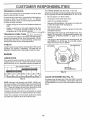
TO CHANGE ENGINE OIL (See Figs, 14 and t5)
COOUNG
The fan and cooling fins of transmission
clean to assure proper cooling_
Determine temperature range expected before oil change,
NI oil must meet API service classification SF, SG or SH
should be kept
Do not attempt to clean fan or transmission while engine is
running or while the transmission is hot To prevent
possible damage to seals, no not use high pressure water
or steam to clean transaxle.
•
Inspect cooling fan to be sure fan blades are intact and
clean
•
inspect cooling fins for dirt, grass clippings and other
materials. To prevent damage to seals, do not use
compressed air or high pressure sprayer.
TRANSAXLE
.
Be sure tractor is on level surface..
o
,
Oil wilt drain more freely when warm
Catch oil in a suitable container.
ti
Remove oil fill cap/dipsticL Be careful notto allow dirt
to enter the engine when changing oilo
Remove drain plug..
°
_
PUMP FLUIDI,,_,/.!T_4
After oil has drained completely, replace oil drain plug
and tighten securely..
Refill engine with oil through oil fill dipstick tube. Pour
slowly. Do not overfill For approximate capacity see
"PRODUCT SPECIFICATIONS"
on page 3 of this
manual,
".'.-- "'. :
"__1_¢/_'
The transaxle was sealed at the factory an_ fluia maintenance is not required for the life of the transaxle. Should
the transaxte ever leak or require servicing, contact your
nearest authorized service center/department.
"
Use gauge on oil fill cap/dipstick for checking level, Be
sure dipstick is in all the way for accurate reading.
Keep oil at "FULL" line on dipstick.
V-BELTS
OIL DRAIN PLUG
AIR SCREEN
Check V-belts for deterioration and wear after 100 hours of
operation and replace if necessary° The belts are not
adjustable, Replace belts if they begin to slip from wearA
ENGINE
LUBRICATION
Only use high quality detergent oil rated with API service
classification SF, SG or SH< Select the oi!'s SAE viscosity
grade according to your expected operating temperature°
SAE VISCOSITY GRADES
.............
l
I
7[.....................
ENGINE OIL
FILL CAPtDIPSTICK
FIG. 15
'_F
90
;_1]"
+30 _
0_
-20"
TEMPERATURE
30 °
-i0 =
32 _' 40 =
0"
RANGE ANTICIPATED
00 °
10'
BEFORE
DO'
20"
101)°
30"
40 _
NEXT OIL CHANGE
CLEAN
FIG. 14
AIR SCREEN
(See Fig. 15)
Air screen must be kept free of dirt and chaff to prevent
engine damage from overheating, Clean with a wire brush
or compressed air to remove dirt and stubborn dried gum
fibers.
NOTE: Although multi-viscosity oils (5W30, 10W30, etc.)
improves starting in cold weather, these multi-viscosity oils
wil! result in increased oil consumption when used above
32"Co Check your engine oil level more frequently to avoid
possible engine damage from running Iow on oil+
Change the oil after every 50 hours of operation or at least
once a year if the tractor is not used for 50 hours in one year°
Check the crankcase oil level before starting the engine
and after each eight (8) hours of continuous use_
19
CUSTOMER RSSPONSnBJLJTUES
CLEAN AIR INTAKE/COOLING
AREAS
ENGINE
OBL FILTER
To insure proper cooling, make sure the grass screen,
cooling fins, and other external surfaces of the engine are
kept clean at all times.
Every t00 hours of operation (more often under extremely
dusty, dirty conditions), remove the blower housing and
other cooling shroud& Clean the cooling fins and external
surfaces as necessary. Make sure the cooling shrouds are
reinstalled.
Replace the engine oil filter every season or every other oil
change if the tractor is used more than 100 hours in one
year.
NOTE: Operating the engine with a blocked grass screen,
dirty or plugged cooling fins, and/or cooling shrouds removed will cause engine damage due to overheating.
RelSlace spark plugs at the beginning of each mowing
season or after every 100 hours of operation, whichever'
occurs first. Spark plug type and gap setting are shown in
"PRODUCT SPECIFICATIONS" on page 3 of this manual.
AIR FILTER
MUFFLER
Inspect and replace corroded muffler and spark arrester (if
equipped) as it could create a fire hazard and/or damage.
SPARK PLUGS
(See Fig. 16)
Your engine wilt not run properly using a dirty air filter.
Clean the foam pre-cleaner after every 25 hours of operation or every season. Service paper cartridge every 100
hours of operation or every season, whichever' occurs first.
Service air cleaner more often under dusty conditions.
= Loosen knob and remove cover.
TO SERVICE PRE-CLEANER
= Slide foam pre-cfeaneroff cartridge°
= Wash it in liquid detergent and water.
= Squeeze it dry in a clean cloth_
o Saturate it in engine oil. Wrap it in clean, absorbent
cloth and squeeze to remove excess oil.
TO SERVICE CARTRIDGE
= Remove nut and cartridge plate.
Gently tap the flat side of the paper cartridge to dislodge dirt. Do not wash the paper cartridge or use
pressurized air, as this will damage the cartridge.
Replace a dirty, bent, or damaged cartridge.
= Reinstall the pre-cteaner (cleaned and oiled) over the
paper cartridge.
= Check rubber seal for' damage and proper position
around stud. Replace if necessary.
o Reassemble air cleaner', cartridge plate, and nut.
:
Reinstall air cleaner cover and secure by tightening
knob.
aN-LINE FUEL FILTER (See Fig. 17)
The fuel filter shoutd be replaced once each season. If fuel
filter becomes clogged, obstructing fuel flow to carburetor,
replacement is required°
o With engine cool, remove filter and plug fue! line
sections.
o
Place new fuel filter in position in fuel line with arrow
pointing towards carburetor.
=
Be sure there are no fuel line leaks and clamps are
properly positioned.
,
lmrnediately wipe up any spilled gasoline,
FIG. 17
CLEANING
o
Ctean engine, battery, seat, finish, etc. of all foreign
matter.
°
Keep finished surfaces and wheels free of al! gasoline,
oil, etc.
°
Protect painted surfaces with automotive type wax,
We do not recommend using a garden hose to clean your
tractor unless the electrical system, muffler, air filter and
carburetor are covered to keep water out. Water in engine
carl result in a shortened engine life.
CARTRIDGE
FOAM
PRE-CLEANER
CARTRIDGE
PLATE
FIG. 16
20
SERVICE A
ADJUSTMENTS
,=....
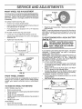
CAUTION:
BEFORE PERFORNING
ANY SERVICE OR ADJUSTIVlENTS:
o
Depress
o
o
o
Place attachment
clutch in "DISENGAGED"
position.
Place ignition
motion key
control
lever
neutral key.
(N) position.
Turn
"OFF"
endinremove
Make sure the blades and all moving parts have completely stopped.
Disconnect spark plug wire from spark plug and place wire where it cannot come in contact with
plug,
o
clutch/brake
pedal fully and set parking brake.
TRACTOR
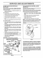
TO REMOVE
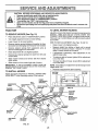
TO LEVEL MOWER
Adjust the mower while tractor is parked on level ground or
driveway°
Make sure tires are properly inflated (See
"PRODUCT SPECIFICATIONS" on page 3 of this manual).
if tires are over or underinfiated, you will not properly adjust
your mower°
I=_OWER (See Fig. 18)
o
Place attachment clutch in "DISENGAGED"
o
Turn height adjustment knob to lowest setting,
o
Lower mower to its lowest position.
=
Remove retainer spring holding anti-swaybar to chassis bracket and disengage anti-swaybar from bracket.
o
Remove retainer springs from suspension
deck and disengage arms from deck.
°
Raise attachment lift to its highest position.
•
Remove two retainer springs from each front link and
remove links.
o
Slide mower forward and remove belt from electric
clutch puliey_
position°
SIDE-TO-SIDE ADJUSTMENT
arms at
= Slide mower out from under right side of tractor.
IMPORTANT': IF AN ATTACHMENT OTHER THAN THE
MOWER DECK 1STO BE MOUNTED ON THE TRACTOR,
REMOVE THE FRONT LINKS.
Raise mower to its highest position°
o
Measure height from bottom of deck curt to ground
level at front corners of mower° Distance *'A" on both
sides of mower should be the same.
°
If adjustment is necessary, make adjustment on one
side of mower only.
•
To raise one side of mower, tighten Iift link adjustment
nut on that side.
o
To lower one side of mower, loosen lift link adjustment
nut on that side.
NOTE: Each half turn of adjustment nut will change mower
height about 3/16".
MOWER
LIFT
LINKS
Recheck measurements
after adjusting.
BOTTOM
OF CURL
Follow procedure described in "iNSTALL MOWER AND
DRIVE BELT" in the Assembly section of this manual,
SUSPENSION
ARMS
(See Figs. 18 and 19)
o
=
TO INSTALL
HOUSING
BO_rTOM
OF CURL
FRONT
SUSPENSION
BRACKET
ADJUSTMENT
NUTS
FIG. 19
BRACKET
CHASSIS
ELECTRIC
CLUTCH
PULLEY
FRONT
SUSPENSION
BRACKET
RETAINER
RETAINER
SPRING
ANTI-SWAY
BAR
FRONT MOWER
BRACKET
RETAINER
SPRINGS
FIG. 18
21
$ERVUOB AND ADJUSTMENTS
.....
i,i
........
'
..........
'
i, i,,,i,,,,i,, i,,i,,, iii
i
....
ii,
__
FRONT-TO-BACK ADJUSTMENT (See Figs. 20 and 21) IMPORTANT: DECK MUST BE LEVEL S1DE-TO-S{DEo IF
THE FOLLOWING FRONT-TO-BACK ADJUSTMENT IS
NECESSARY, BE SURE TO ADJUST BOTH FRONT LINKS
EQUALLY SO MOWER WILL STAY LEVEL SIDE-TO-SIDE.
To obtain the best cutting results, the mower housing
should be adjusted so the front is approximately 1/8" to 1/2"
lower than the rear when the mower is in its highest
position.
Check adjustment on right side of tractor. Measure distance "F" directly in front of and behind the mandrel at
bottom edge of mower hbusing as shown.
•
Before making any necessary adjustments, checkthat
both front links are equal in length.
o If links are not equal in length, adjust one link to same
length as other link.
o To lewerfront of mower'housing, loosen nut"G" on both
front links an equal number of turns.
o When distance "F" is 1/8" to 1/2" lower at front than
rear, tighten nut"H" against trunnion on both front links.
o To raise front of mower housing, loosen nut "H" from
trunnion on both front links. Tighten nut "G" on both
front links an equal number' of turns.
o When distance "F" is 1/8" to 1/2" lower at front than
rear, tighten nut "H" against trunnion on both front
links.
TO REPLACE
NOTE: Each full turn of nut"G" will change dim. "F" by
approximately 3/8".
o
Recheck side-to-side adjustment.
=
,i..............
,
i
iVIOWER DRIVE BELT
MOWER DRIVE BELT REMOVAL (See Fig. 22) o
o
Park tractor'on a level surface. Engage parking brake.
Remove four screws from LH. mandrel cover and
remove cover.
o
Roll belt over the top of LH. mandrel pulley,,
o
Remove belt from electric clutch pulley.
o
, Remove belt from idler pulleys.
o
Remove any dirt or grass clippings which may have
accumulated around mandrels and entire upper deck
surface.
°
Check primary idler arm and two idlers to see that they
rotate freely.
°
Be sure spring is securely hooked to primary idler arm
and bolt in mower housing.
MOWER DRIVE BELT INSTALLATION (See Fig. 22) •
Install belt in both idlers. Make sure belt is in both belt
keepers at the idler's as showrL
o
Install new belt onto electric clutch pulley.
o
Roll belt into upper groove of LH. mandrel pulley.
•
Carefully check belt routing making sure belt is in the
grooves correctly and inside belt keepers.
Reassemble LH. mandrel cover.
L.H.
MANDREL
COVER
MANDREL
SCREWS
SPRING
IDLER
PULLEYS
ELECTRIC
CLUTCH
PULLEY
PRIMARY
IDLER
ARM
FIG. 20
BOLT IN
MOWER
HOUSING
BOTH FRONT LINKS SHOULD BE EQUAL IN LENGTH
MANDREL
MOWER
DRIVE BELT
BELT
KEEPER
FiG. 22
NUT"H"
FRONTLINKS
FIG. 21
22
i
,
i
,,,,,, ,,,.
,.......
, .....
,,,
,,i ......
ii,
i ,,,,i,,,, iii..........
;;;,_
,
SERVmCE AND ADJUSTMENTS
......
i
TO REPLACE
MOWER
i1,,,,,11
.....................
i ,i,,,,,i,,
BLADE
NOTE: After installing a new electric clutch, run tractor at
full throttle and engage and disengage electric clutch 10
cycles to wear in clutch plate°
DRIVE BELT
(See Fig. 23)
Park the tractor on level surface. Engage parking brake.
°
Remove mower drive belt (See'TO REPLACE MOWER
DRIVE BELT" in this section of this manual)_
o Remove mower (See ''TO REMOVE MOWER" in this
section of this manual).
= Remove four screws f[om R.H. mandrel cover and
remove cover_ Unhook spring from bolt on mower
housing.
•
Carefully roll belt off R.H. mandrel pulley.
•
Remove belt from center mandrel pulley, idler pulley,
and LHo mandrel pulley.
o Remove any dirt or grass which may have accumulated around mandrels and entire upper deck surface.
o Check secondary idler arm and idler to see that they
rotate freely.
o Be sure spring is hooked in secondary idler arm and
sway-bar bracket,
o
Install new belt in lower groove of LH.. mandrel pulley,
idler pulley, and center mandrel pulley as shown.
o
Roll belt over R°H. mandrel pulley. Make sure belt is in
all grooves properly.
o Reconnect spring to bolt in mower housing and reinstall Roll. mandrel cover.
•
Reinstall mower to tractor (See "INSTALL MOWER
AND DRIVE BELT" in the Assembly section of this
manual).
,,
Reassemble mower drive belt (See 'q'O REPLACE
MOWER DRIVE BELT' in this section of this manual),
L.H.
MOWER
BLADE
DRIVE BELT
/
/
NYLON LOCKNUT (3)
BRAKE PLATE
FIG, 24
TO ADJUST
BRAKE (See Fig. 25)
Your tractor is equipped with an adjustable brake system
which is mounted on the side of the transaxleo
If tractor requires more than six (6) feet stopping distance
at high speed in highest gear, then brake must be adjusted°
CENTER
MANDREL
MANDREL
COVER
•
Depress clutch/brake pedal and engage parking brake..
o
Measure distance between brake operating arm and
nut "A" on brake rod.
o
If distance is otherthan 1-1/2", loosen jam nut and turn
nut 'W' until distance becomes 1-t/2". Retighten jam
nut against nut "A"o
°
Roadtesttractorfor
proper stopping distance as stated
above, Readjust if necessary. If stopping distance is
still greater than six (6) feet in highest gear, further
maintenance is necessary° Contact your nearest authorized service center/department.
WITH PARKING BRAKE "ENGAGED"
NUT "A"
SECONDARY/
IDLERARM/
SPRING"
SWAY-BAR
BRACKET
SCREW
IDLER
PULLEY
/
_._
OPERATING
FIG, 23
TO ADJUST ATTACHMENT CLUTCH
(See Fig. 24)
The electric clutch should provide years of service_ The
clutch has a built-in brake that stops the pulley within 5
seconds. Eventually, the internal brake will wear which
may cause the mower blades to not engage, or, to not stop
as required. Adjustments should be made by your nearest
authorized service center/department.
o Make sure attachment clutch and ignition switches are
in "OFF" position.
o Adjust the three nylon locknuts until space between
clutch plate and rotor measures .0t2" at all three slot
locations cut in side of brake plate.
FIG. 25
23
TO REPLACE
MOTION
TO ADJUST
DRIVE BELT
(See Fig. 26)
MOTION
CONTROL
LEVER
(See Fig. 27)
Park the tractor on level surface° Engage parking brake°
For ease of service there isa belt installation guide decal on
bottom of left footresL
The motion control lever has been preset at the factory and
adjustment should not be necessary.
if for any reason the motion control lever wilt not hold its
position while at a selected speed, it may be adjusted at the
friction pack located on the right side of chassis°
•
Remove mower (See 'q'O REMOVE MOWER" in this
section of this manual.)
BELT REMOVAL o
.
Engage parking brake (creates slack i n belt).
Remove belt from clutching and fan idler pulleys_
•
Loosen belt keeper above transaxle pulley.
o
Remove belt fronl transaxle pultey_
o
Remove belt from engine pulley and front V=idler pulley.
•
Park tractor on level surface. Stop tractor by turning
•ignition key to "OFF" position and engage parking
brake.
o
Place motion control lever in neutral (N) position.
o
While holding iocknut, loosen jam nut
,,
Tighten Iocknut 1/4turn.
o
While holding Iocknut, tighten jam nut securely°
o
Pull belt out of all belt keepers and remove from tractor.
BELT INSTALLATION o
NOTE" If for any reason the effort to move the motion
control lever becomes too excessive, reverse the above
adjustment procedure by loosening iocknut 1/4 turn.
•
Place V part of belt into grooves on engine pulley and
front V-idler, making sure to route belt inside of all belt
keepers.
Road test tractor after adjustment and repeat procedure if
necessary.
•
Route belt on dght side, coming from V-idler, towards
back of tractor, above midspan belt keeper and to top
of transaxle pulley.
°
Route belt on left side, coming from engine pulley,
towards back of tractor and through loop in midspan
belt keeper°
o
Place V part of belt into grooves on transaxte and fan
idler pulleys, making sure to route belt inside of all belt
keepers.
=
Retighten belt keeper above transaxle pulley.
o
Place belt around clutching idlers as shown, making
sure to route belt inside of all belt keepers.
o
Check to be sure belt is positioned correctly and is on
proper side of aII belt keepers°
Reinstall mower.
°
IMPORTANT;
LOCKNUT
JAM NUT
CHECK BRAKE ADJUSTMENT,,
TRACTOR V-BELT DRIVE SCHEMATIC
VIEWED FROM L.H, SIDE OF TRACTOR
CLUTCHING
ENGINE
PULLEY
CLUTCHING
IDLER _
\
FIG. 27
TRANSAXLE
BELT
TRANSIVllSSiON REMOVAL/REPLACEMENT
Should your transmission require removal for service or
replacement, it should be purged after reinstallation before
operating the tractor. See "PURGE TRANSMISSION" in
Operation section of this manual.
ABOVE
V-IDLER
KEEPER
TO ADJUST STEERING WHEEL ALIGNMENT
'L=NGINE
PULLEY
BELT
1 TWISTS
[
If steering wheel crossbars are not horizontal (left to right)
when wheels are positioned straight forward, remove steering wheel and reassemble per instructions in the Assembly
section of this manual.
BELT
KEEPER
FAN
IDLER
AS VIEWED FROM BOTTOM
FiG. 26
24
SERVICE AN
FRONT
WHEEL
TOE-IN
ADJUSTMENTS
ADJUSTMENT
Front wheel toe-in is required for proper steering operation,
Toe-in was set at the factory and adjustment should not be
necessary. If parts in the front axle or steering mechanism
have been replaced or damaged, check toe-in and adjust
if necessary.
RETAINING
RING
AXLE
COVER
TO CHECK TOEqN (See Fig. 28) °
Position front wheels straight ahead_
o
°
FIG. 30
Measure distance between wheels at front and rear of
tires (dimensions "A" and "B").
Front dimension "A" should be 1/8" to 1/4" less than
rear dimension "B"..
°
Repair tire and reassemble, Replace
bolts securely°
NOTE: To seal tire punctures and prevent
slow leaks, tire sealant may be purchased
parts dealer. Tire sealant also prevents
corrosion..
TO ADJUST TOE-IN (See Figs. 28 and 29) Loosen jam nuts at adjustment sleeves on tie rod°
,,
Adjusttie rod until dimension"A" is I/8" to 1/4" less than
dimension "B"
•
Tighten jam nuts securely.
TO START ENGINE
(See Fig, 31)
ADJUSTMENT
SLEEVES
_"
....
/
TIE ROD
FIG. 29
WHEEL
CAMBER
The front wheel camber is not adjustable on your tractor, if
damage has occurred to affect the front wheel camber,
contact your nearest authorized service center/departmenL
TO REMOVE
WHEEL
WITH A WEAK
FOR REPAIRS
FRONT WHEEL (See Fig. X) °
Block up axle securely._
•
Remove axle cover, retaining ring and washers to allow
wheel removal.
"POSITIVE"
(+)
"NEGATIVE"
o
o
Repair tire and reassemble°
Replace washers and snap retaining ring securely in
axle groove.
= Replace axle cover_
REAR WHEEL
°
°
BATTERY
If your battery is too weak to start the engine, it should be
recharged. If "jumper cables" are used for emergency
starting, follow this procedure:
IMPORTANT: YOUR TRACTOR IS EQUIPPED WITH A 12
VOLT NEGATIVE GROUNDED SYSTEM
THE OTHER
VEHICLE MUST ALSO BE A 12 VOLT NEGATIVE
GROUNDED SYSTEM. DO NOT USE YOUR TRACTOR
BATTERY TO START OTHER VEHfCLES.
TO ATTACH JUMPER CABLES •
Connect each end of the RED cable to the POSITIVE
(+) terminal of each battery, taking care not to short
against chassis,.
,
Connect one end of the BLACK cable to the NEGATIVE (-) terminal of fully charged battery,
•
Connect the other end of the BLACK cable to good
CHASSIS GROUND, away from fuel tank and battery,
TO REMOVE CABLES, REVERSE ORDER o BLACK cable first from chassis and then from the fully
charged battery.
•
RED cable last from both batteries.
FIG. 28
FRONT
flat tires due to
from your local
tire dry rot and
ate explosive gases. Keep sparks,flame
and smoking materials away from batteries.
wear batteries
eye protection
CAUTION:Always
Lead-acid
generwhen around batteries.
'&
JAM NUTS'_
and tighten hub
Block rear axle securely
Remove five (5) hub bolts to allow wheel removal.
FIG. 31
25
(-)
TO REPLACE
HEADLIGHT
TO REMOVE
BULB
HOOD
AND GRILL
ASSEMBLY
°
Raise hood°
(See Fig. 33)
,
Pull bulb holder out of the hole in the backside of the
grill°
o
Raise hood.
o
Unsnap headlight wire connector.
o
Replace bulb in holder and push bulb holder securely
back into the hote in the backside of the grill,
-
Standinfrontoftractor.
Grasphoodatsides,tilttoward
engine and lift off of tractor.
°
Close hood,
o
To replace, reverse above procedures.
INTERLOCKS
AND RELAYS
Loose or damaged wiring may cause your tractor to run
poorly, stop running, or prevent it from starting.
,
HEADLIGHT
WIRE
CONNECTOR
Check wiring, See electrical wiring diagram in the
Repair Parts section of this manual.
HOOD
TO REPLACE
FUSE
Replace with 30 amp automotive-type plug_in fuse.
fuse holder is located behind the dash.
TO ADJUST ATTACHMENT
(See Fig. 32)
The
LiFT SPRING
.
While holding spring bushing with wrench, loosen jam
nut.
.
Turn adjustment bolt clockwise to extend spring and
reduce lift effort for heavier attachments.
•
Turn adjustment
tachmentso
bolt counterclockwise
for' lighter at-
°
Retighten jam nut against spring bushing.
IMPORTANT: DO NOT ADJUST FOR MAXIMUM SPRING
TENSION WHEN USING LIGHT ATTACHMENTS SUCH
AS A MOWER. ADJUST LiFT LEVER SPRING TO AID IN
LIFTING ATTACHMENT. DO NOT OVERPOWER SPRING.
WHEN REMOVING ATTACHMENT, ALWAYS ADJUST
SPRING TENSION TO ITS LOWEST POSITION.
FIG. 33
ENGINE
TO ADJUST THROTTLE
CONTROL
CABLE
(See Fig. 34)
ADJUSTMENT
SPRING BUSHING
JAM NUT
The throttle control has been preset at the factory and
adjustment should not be necessary_ Check adjustment as
described below before loosening cable° If adjustment is
necessary, proceed as follows:
•
With engine not running, move throttle control lever to
fast (,_) position.
°
Check that speed control lever is against stop screw. If
it is not, loosen casing clamp screw and pull throttle
cable until lever is against screw. Tighten clamp screw
securely.
ATTACHMENT
LIFT SPRING
FIG. 32
26
SERV!CE AND ADJUSTMENTS
,, ,, ,,,,,, ,,, ....
....... =,,.........
iDLE FUEL
ADJUSTING
NEEDLE
TO ADJUST CARBURETOR
IDLE SPEED
SCREW
o
CHOKE
CONTROL
CABLE
Be sure you have a clean air filter, and the throttle
control cable is adjusted properly (see 'q'O ADJUST
THROTTLE CONTROL CABLE" in the Service and
Adjustments section of this manual).
o
With engine off turn idle fuel adjusting needle in (clockwise) closing it finger tight and then turn out (counterclockwise) 1 turn
FINAL SETTING -
STOP
CLAMP
SCREW
•
Start engine and allow to warm for five minutes_ Make
final adjustments with engine running and shift/motion
control lever in neutral (N) position.
•
The high idle is set at the factory and cannot be
adjusted.
o
idle speed settinq - With throttle control lever in slow
(=_,) position, engine should idle at 1200 RPMo If
engine idles too slow or fast, turn idle speed adjusting
screw in or out until correct idle is attained.
•
!die fuel needle Settinq - With throttle control lever in
slow (,,_) position, turn idle fuel adjusting needle in
(clockwise) until engine speed decreases and then
turn out (counterclockwise) approximately 3/4 turn to
obtain the best low speed performance
.
Recheck idle speed° Readjust if necessary.
FIG. 34
TO ADJUST CHOKE CONTROL
(See Figs. 34 and 35)
The choke control has been preset at the factory and
adjustment should not be necessary, check adjustment as
described below before loosening cable. If adjustment is
necessary, proceed as follows:
With engine not running, move choke control (located
on dash panel) to full choke (1\1)position.
•
Remove air cleaner cover, filter and cartridge plate to
expose carburetor choke (See "AIR FILTER" in the
Customer Responsibilities section of this manual).
o Choke should be closed. If it is not, loosen casing
clamp screw and move choke cable until choke is
completely closed. Tighten casing clamp screw securely.
o Reassemble air cleaner°
CLOSED
(See Fig. 34)
The carburetor has been present at the factory and adjustmerit should not be necessary. However, minor adjustment
may be required to compensate for differences in fuel,
temperature, altitude or Ioado tf the carburetor does need
adjustment, proceed as follows:
In general, turning the adjusting needles in (clockwise)
decreases the supply of fuel to the enginegiving a !eaner
fuel/air mixture. Turning the adjusting needles out (counterclockwise) increases the supply of fuel to the engine
giving a richer fue!/air mixture.
lrCtPORTANT: DAMAGE TO THE NEEDLES AND THE
SEATS IN CARBURETOR MAY RESULT IF SCREW tS
TURNED 1N TOO TIGHT.
PRELIMINARY SETTING -
THROTTLE
CONTROL
CABLE
SCREW
" i ...................
ACCELERATION
•
FOR
TEST -
Move throttle control lever from slow (,_) to fast
position° If engine hesitates or dies, turn idle
adjusting needle out (counterclockwise) 1/8 turn
peat test and continue to adiust, if necessary,
engine accelerates smoothly.
('_v)
fuel
Reuntil
High speed stop is factory adjusted. Do not adjust-damage
may result.
IMPORTANT:
NEVER TAMPER WITH THE ENGINE
GOVERNOR, WHICH IS FACTORY SET FOR PROPER
ENGINE SPEED. OVERSPEEDING THE ENGINE ABOVE
THE FACTORY
HIGH SPEED SETTING
CAN BE
DANGEROUS IF YOU THINKTHE ENGINE-GOVERNED
HIGH SPEED NEEDS ADJUSTING, CONTACT YOUR
NEAREST
AUTHORIZED
SERVICE
CENTER/
DEPARTMENT, WHICH HAS PROPER EQUIPMENT AND
EXPERIENCE
TO
MAKE
ANY
NECESSARY
ADJUSTMENTS.
FIG. 35
27
STORAGE
ENGINE
Immediately prepare your tractor for storage at the end of
the season or if the tractor will not be used for 30 days or
nore_
&
FUEL SYSTEM
IMPORTANT:
IT IS IMPORTANT TO PREVENT GUM
DEPOSITS FROM FORMING IN ESSENTIAL FUEL
SYSTEM PARTS SUCH AS CARBURETOR, FUEL FILTER,
FUEL HOSE, OR TANK DURING STORAGE.
ALSO,
EXPERIENCE iNDICATES THAT ALCOHOL BLENDED
FUELS (CALLED GASOHOL OR USING ETHANOL OR
METHANOL) CAN ATTRACT MOISTURE WHICH LEADS
TO SEPARATION AND FORMATION OF ACIDS DURING
STORAGE
ACIDIC GAS CAN DAMAGE THE FUEL
SYSTEM OF AN ENGINE WHILE IN STORAGE,
CAUTION: Never store the tractor with
gasoline in the tank inside a building
where fumes may reach an open flame
or spark.
Allow the engine to cool
before storing in any enclosure.
r
ii
TRACTOR
Remove mower from tractor for winter storage_ When
mower is to be stored for a period of time, clean it thor:
oughty, remove all dirt, grease, leaves, etc. Store in a
clean, dry area.
o
Clean entire tractor (See"CLEANING"in the Customer
Responsibilities section of this manual).
°
Inspect and replace belts, if necessary (See belt replacement instructions in the Service and Adjustments
section of this manual).
o
Lubricate as shown in the Customer Responsibilities
section of this manual.
°
Be Sure that all nuts, bolts and screws are securely
fastened. Inspect moving parts fordamage, breakage
and wear. Replace if necessary_
=
Touch up ali rusted or' chipped paint surfaces; sand
lightly before painting.
Fully charge the battery for storage.
=
After a pedod of time in storage, battery may require
recharging.
o
To help prevent corrosion and power leakage during
long periods of storage, battery cables should be
disconnected and batterycleaned thoroughly (see'TO
CLEAN BATTERY AND TERMINALS" in the Customer Responsibilities section of this manual),
=
Drain the fuel tank.
o
Start the engine and let it run until the fuel lines and
carburetor are empty°
•
Never use engine orcarburetor cleaner products in the
fuel tank or permanent damage may occur.
Use fresh fuel next season°
°
NOTE:
Fuel stabilizer is an acceptable alternative in
minimizing the formation of fuel gum deposits during storage, Add stabilizer to gasoline in fuel tank or storage
container. Always follow the mix ratio found on stabilizer
container, Run engine at teast 10 minutes after adding
stabilizer to allow the stabilizer to reach the carburetor. Do
not drain the gas tank and carburetor if using fuel stabilizer,
ENGINE
OIL
Drain oil (with engine warm) and replace with clean engine
oil. (See "ENGINE" in the Customer Responsibilities
section of this manual)_
BATTERY
.
o
CYLINDERS
After cleaning, leave cables disconnected and place
cables where they cannot come in contact with battery
terminals.
o
Remove spark plug(s)_
o
Pour one ounce of oil through spark plug hole(s) into
cyfinder(s)o
,,
Turn ignition key to"START" position for a few seconds
to distribute oil
°
Replace with new spark plug(s).
OTHER
*
Be sure battery drain tube is securely attache&
o
Do not store gasoline from one season to another.
°
If battery is removed from tractor for storage, do not
store battery directly on concrete or damp surfaces.
°
Replace your gasoline can if your can starts to rust.
Rust and/or dirt in your gasoline will cause problems.
o
If possible, store your tractor indoors and cover it to
give protection from dust and dirt.
=
Cover your tractor with a suitable protective cover that
does not retain moisture. Do not use ptastic. Plastic
cannot breathe which allows condensation to form and
will cause your tractor to rust.
IMPORTANT: NEVER COVERTRACTOR WHILE ENGINE
AND EXHAUST AREAS ARE STILL WARM
28
i
,,,, ,i,,,i ,,u==,
:
..........
,, ......................
TIROUBLESHOOT NG
POUNTS
i ,,_11
CORRECTION
PROBLEM
CAUSE
Will not start
1,
Out of fuet,
2
3
4,.
5.
6,
7.
Engine not "CHOKED"
Engine flooded
Bad spark plug
Dirty air filter,
Dirty fuel filter
Water in fuel
8.
9
Looseor damaged widng
Carburetor out of adjustment,
10
Hard to start
IL
=
' ""±
properly
Engine valves out of adjustmenL
1.
Fill fuet tank
2
3,
4,
5
6
7
See "TO START ENGINE" in Operation section
Waft several minutes before attempting to start
Replace spark plug,
Clean!replace air filter.
Reptace fuel filter,
Drain fuel tank and carburetor, refill tank with fresh
gasoline and replace fuel filter
8.
9,
Check all wiring,
See "To Adjust Carburetor"
section.
10,
Contacl an authorized
in Service Adjustments
service center/department
1.,
2
3.
4
5,
6.
7
Dirty air fitter
Bad spark plug,
Weak or dead battery
Dirty fuel tilter,
Stale or dirty fueL
Loose or damaged widng.
Carburetor out of adjustment.
1.
2
3,
4
5.
6
7.
Ctean/replaceair
filter
Replace spark p_ug,
Recharge or replace battery
Replace fuef lifter
Drain fuel tank and refill with fresh gasoline
Check al! wiring,
See =To Adjust Carburetor" in Service Adjustments
sect;,on_
8.
Engine valves out of adjustmenL
8o
Contact an authorized service center/department,
Depress cfutch/brake pedal,
Disengage attachment c_utch
Recharge or replace battery
Replace fuse,
Clean battery terminals
Check all wiring
Check/replace Ignllion switch
Check/replace solenoid or starter.,
Contact an authorized service center/department
.................
i,ii,
'"'"
,,,i....
1.
2
3
4.
Clutch/brake pedal net depressed.
Attachment clutch is engaged,
Weak or dead battery,
Blown fuse.
5,
6
7
8,
9
Corroded battery terminals,,
Loose or damaged widng
Faulty ignition swilch
Faulty solenoid or starter.
Faulty operator presence switeh(es).
1
2,
3
4.
5.
6,
7.
&
9,
Engine clicks but will not
start
1
2,
3
4
Weakordead
battery
Corroded battery terminals
Loose or damaged wiring.
Faufty solenoid or starter
I.
2.
3
4.
Recharge or replace battery,
Clean battery terminals.
Check a_l wiring
Check/replace solenoid or starter
Loss of power
I
2
&
4r
5
6,
7.
8.
9.
Cutting too much grass/too fast
Throttle in"CHOKE" position,
Build-up of grass, leaves and trash under mower,
Dirty air fitter.
Low elf level/dirty oil,
Faulty spark plug
Dirty fuel filter
Stale or dirty fuel
Water in fue!.
1.
2
3,
4.
56.
7
8.
9_
Set tn "Higher Cut" position/reduce speed
Adjust throttle control
Clean underside of mower housing,
Clean!replace air fitter,
Check oil level/change oil.
Clean and regap or change spark plug
Replace fuel fitter
Drain fuel tank and refill with fresh gasoline.
Drain fuel tank and carburetor, refiti tank with fresh
Engine witl not turn over
10.
11,
12.
t3
14
Spark ptug wire loose.
Dirty engine air screen/fins
Dirtytclogged mufller.
Loose or damaged wiring
Carburetor out of adjustmenL
10,
t 1.
12,
13,
t4
gasoline and replace fuef filter.
Connect and tighten spark ptug wire
Ciean engine air screen/rinse
Clean/replace muffler
Check al! widng,
See "To Adjust Carburetor" in Service Adjustments
section
15
Engine valves out of adjustment,
15,
Contact an authorized service center/department
r,i
Excessive vibration
•r,, •
1
2
Worn, bent or loose blade,.
Bent blade mandrel
1
2.
Replace blade Tighten blade bolt.
Replace blade mandrel
3
Loose/damaged
3.
Tighten loose part(s)
part(s),
29
Repface damaged parts
TROUBLESHOOTING
............
.........
POINTS
.................................
PROBLEM
u.u.
CAUSE
=.,u.....
CORRECTION
,.,,,,.,
Engine continues to run
when operator leaves seat
with a_achment clutch
engaged
1.
Poor
cut
- uneven
Mower blades will not
rotate
Faulty operator-safety
presence control system.
1.
Check wiring, switches and connections
tf not
corrected, contact an authorized service center:/
department
1_ Worn, bent or loose blade.
2
Mower decl_ not level
I.
2
Replace blade Tighten blade boil
Levelmewet
deck.
3.
4
Buildup of grass, leaves, and trash under mower
Bent blade mandrel.
5.
Clogged mower deck vent holes from buildup of
grass, leaves, and trash around mandrels
3
4.
5.
Clean underside of mower housing
Replace bfade mandrel.
Clean around mandrels to open vent holes
1.
Obstruction
t
Remove obstruction.
2o
3o
4.
Worn/damaged mower drive belt
Frozen idler pulley.
Frozen b)ade mandrel
2.
3
4.
Replace mower drive belt
Replace idler pulley.
Replace blade mandrel
Poor grass discharge
2
3
4
5
6
7
8
9
10.
11..
In clutch mechanism
Engine speed too slow
Travel speed too fast
Wet grass
Mower deck not level_
Low/uneven tire air pressure
Warn, bent or loose blade
Buildup of grass, leaves and trash under mower
Mower drive belt worn.
Biades improperly installed
improper blades used
Clogged mower deck vent holes from buildup of
grass, leaves, and trash around mandrels
1.
2.
3
4.
5
6.
7
8.
9
10
11
.,..._
Ptace throttle control in "FAST" position
Shift to slower speed.
A_low grass to dry before mewing
Level mower deck
Checktires for proper air pressure.
RepJace/sharpen blade. Tighten blade bolt
Clean underside of mower housing
Replace mower ddve belt
ReinstatJ blades sharp edge down
Replace with blades iisted in this manual
Clean around mandrels to open vent holes
Headlight(s) not working
(if so equipped)
1
2
3
4.
5
Switch is "OFF
Bulb(s) burned out
Faulty light switch.
Loose ordamaged
widng
Blown fuse=
1
Turn switch "ON"
2.
3
4
5.
Replace bulb(s)
Cheeldrep_ace light switch
Check wiring and connections
Replace fuse
Battery will not charge
1.
2
Bad battery cell(s)
Poor cable connections
1.
2.
Replace battery.
Checldclean aH connections
3
4
Fautty regulator (if so equipped)
Faulty altemator
3.
4.
Replace regulator.
Replace alternator.
t.oss of drive
1.
2.
3.
Freewheel controt in "disengaged" position.
Motion ddve belt worn, damaged, or broken
Air trapped in transmission during shipment
or servicing.
t
2
3
Place freewheel control in "engaged" position
Replace motion ddve bait
Purge transmission
Engine "backfires"
when turning engine
"OFF"
1•
Engine throttle control not set at "SLOW"
position for 30 seconds before stopping engine.
1
Move throttle control to "SLOW" position and allow
to idie for 30 seconds before stopping engine.
.,,_.
,
-
30