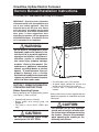
1
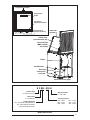
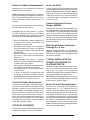
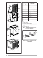
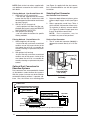
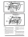
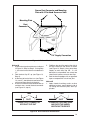
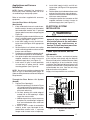
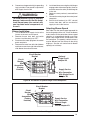
Downflow, Upflow Electric Furnaces
Owners Manual/Installation Instructions
E3 Series (Air Conditioner/Heat Pump Air Handler)
IMPORTANT: Read this owner information
to become familiar with the capabilities and
use of your heating appliance. Keep this
literature where you will have easy access
to it in the future. If a problem occurs, check
the instructions and follow recommendations given. If these suggestions don’t
eliminate your problem, call the appropriate
NORDYNE distributor. A distributor service
list is included with this appliance.
WARNING:
Do not store or use gasoline or other
flammable vapors and liquids in the
vicinity of this or any other appliance.
Improper installation, adjustment,
alteration, service or maintenance
can cause injury, property damage,
or death. Refer to this manual. For
assistance or additional information
consult a qualified dealer or service
agency. To avoid personal injury or
property damage, ask a service
technician to inspect the furnace and to
replace any part of the control system
which has been under water.
SECTION 1. OWNER INFORMATION
OPERATING INSTRUCTIONS
Before Operating System
Before operating your heating/cooling system
(see Figure 1), make sure that:
• Control panel covers are closed.
• Blower and/or relay control plugs are
plugged in.
• Fan switch is set to “AUTO” (E3EH units
only).
CAUTION:
No user serviceable parts inside
control panel. DO NOT OPEN.
• Circuit breakers are in “ON” position.
• All power supply switches for furnace and
outside unit (if installed) are turned on.
• Furnace door is closed and properly
latched.
Refer to the owner’s manual supplied with the
optional heat pump or air conditioner for further
information.
CAUTION:
For optional A/C or H/P systems,
always wait at least five minutes after
the system shuts off before restarting
the system. Observe this procedure
when operating the system per the
following instructions.
2
Temperature Selector
10
20
30
Temperature
Scales
50 60 70 80 90
Fan Switch
(optional sub-base)
SYSTEM
HEAT OFF COOL
VENTILATE
ON AUTO
System Switch
(optional sub-base)
Indoor Coil
(optional)
Coil Air Filters
(used with indoor coil)
Furnace Air Filter
(NOT used with
coil air filters)
Blower
Circuit Breakers
Data Label
Control Panel
Cover (left)
Control Panel Cover (right)
Figure 1. Furnace Parts Identification
E 3 EB - 010 H
Product Type
E - Electric Furnace
Electrical Code
H - 240-1-60
Generation
3 - Third Series
Primary Capacity
010 - 10 kw
012 - 12 kw
015 - 15 kw
017 - 17 kw
020 - 20 kw
023 - 23 kw
Product Identifier
EB - A/C Blower Equipped Relay
EX - Multi-Speed, X13 Motor
Used with Platinum Series
Model Identification
3
To Operate System in Cooling Mode
To Shut Off System
NOTE: The “FAN ON/FAN AUTO” (fan switch)
and “HEAT/OFF/COOL” (system switch) are
located either on your thermostat (if it’s supplied
with a sub-base) or on the relay box added to
your furnace.
1.
1.
2.
3.
4.
Make sure blower selector switch is on
“Auto.”
Set fan switch to “AUTO.”
Set system switch to “COOL.”
Set thermostat temperature selector to
desired comfort level.
To Operate System in Heating Mode
1.
2.
3.
4.
Make sure blower selector switch is on
“Auto.”
Set fan switch to “AUTO.”
Set system switch to “HEAT.”
Set thermostat temperature selector switch
to desired comfort level.
2.
3.
Make sure blower selector switch is on
“Auto”.
Set thermostat temperature selector to
lowest temperature setting, OR...
For thermostats with optional sub-base (see
Figure 1), or for systems with relay box, set
system switch to “OFF.”
WARNING:
To prevent hazard of electrical shock
and injury from moving parts, be
certain the thermostat is off and the
furnace circuit breaker(s) are in the
“OFF” position before servicing. Close
and properly latch the outer door after
doing the following recommended
maintenance.
MAINTENANCE INSTRUCTIONS
NOTE: Allow at least one hour for the room temperature to stabilize before you make a second
adjustment to the thermostat setting. Once the
desired comfort level is established, make only
small adjustments to the thermostat setting to
meet changing temperature conditions.
To Operate Blower Continuously
1.
2.
Set blower selector switch to “ON” for summer
air circulation only (see Figure 1),
OR
If thermostat is equipped with optional
heating/cooling sub-base or relay box (see
Figure 1), set fan switch to “ON.”
To Balance Air Distribution
1.
2.
3.
4.
4
On a typical day, set thermostat selector to
desired comfort level and operate system for
several hours with all air registers open.
With system on, check temperature in all
rooms.
Partially close registers in rooms that are
too warm (in heating mode) or too cool
(in cooling mode) and in rooms that are
infrequently occupied.
Re-check room temperature and adjust
registers as needed.
Regularly
NOTE: If a cooling coil is installed, furnace
filter is not used.
1. Replace furnace air filter (see Figure 1),
OR...
2. Remove coil filters, wash, and allow to dry.
Re-install coil filters to original positions.
3. Vacuum or wipe clean interior of furnace
cabinet.
4. Clean all lint and dust from around furnace.
Every Six Months
1. Vacuum or wipe away any dust or lint on
blower motor.
Before Each Heating Season
NOTE: If a cooling coil is installed, furnace
filter is not used.
1. Replace furnace air filter (see Figure 1),
OR
2. Remove coil filters, wash, and allow to dry.
Re-install coil filters to original positions.
3. Have a qualified serviceman inspect all
furnace components and field wiring and
clean and service heating system as
needed. If this furnace was installed with
aluminum power supply wiring, have serviceman periodically check all connections
to prevent possible equipment failure and/or
fire hazard. Do not attempt any service
function yourself which requires opening
furnace control panel covers.
BEFORE YOU CALL A SERVICEMAN
1.
2.
3.
4.
5.
Make sure thermostat temperature selector
is set above room temperature for heating
or below room temperature for cooling. If
thermostat is equipped with heating/cooling sub-base, make sure system switch
(see Figure 1) is set to “HEAT” for furnace
operation or set to “COOL” for optional airconditioning operation.
Check main household service panel to
see if appropriate circuit disconnect(s) for
appliance power supply is on.
Refer to instructions under Before Operating
System for pre-operation checks.
Refer to instructions under Before Each
Heating Season for maintenance procedures and recommended service checks.
Refer to owner’s manual provided with
optional air conditioner or heat pump (if
installed) for service and maintenance.
NOTE: All servicing of this heating appliance
other than the normal maintenance described in
this section must be done by authorized trained
service personnel. Do not open the control
panels (see Figure 1) at any time.
Please specify the complete model and serial
numbers shown on the furnace data label (see
Figure 1) for all warranty service and when ordering replacement parts or optional equipment.
Refer to the replacement parts list provided with
the furnace for part numbers.
OPTIONAL AIR CONDITIONER
AND HEAT PUMP
Your E3 Series electric furnace is approved for
use with an optional central air conditioner or a
heat pump. To adapt this heating appliance to
a “total comfort system,” contact your nearest
NORDYNE distributor.
Optional air conditioners and heat pumps are
listed by Underwriters’ Laboratories (UL) or
Environmental Testing Laboratories (ETL) and
certified by ARI and the Canadian Standards
Association (CSA), or Warnock Hersey or ETLC.
These cooling systems include energy-saving components to provide maximum cooling
performance at electrical energy usage levels
established by federal standards. Refer to the
operation instruction label on your furnace for
the optional air conditioning equipment approved
for your heating appliance.
SECTION 2.
INSTALLER INFORMATION
GENERAL
These instructions and specifications are primarily intended to assist qualified individuals
experienced in the proper installation of home
heating and air conditioning appliances. Some
local codes require licensed personnel for the
installation and service of this type of equipment. Approved installation, operation, and
maintenance of this central heating system
appliance must be in accordance with the listed
specifications contained in these instructions
and other documents supplied with the furnace
and/or optional air conditioning equipment. Refer
to local authorities having jurisdiction for further
information.
Before beginning installation, read these instructions thoroughly. Follow all warnings and cautions
in the instructions and on the unit.
Improper installation, service adjustment, or
maintenance can cause explosion, fire, electrical shock or other conditions which may result
in personal injury or property damage. Unless
otherwise noted in these instructions, use only
factory-authorized kits and accessories when
modifying this product.
Overview of E3 Furnace
E3E(-) Series electric furnaces are available in
two models. E3EH models are equipped with the
standard two-speed blower. E3EH models can
be easily converted for use with NORDYNE splitsystem air conditioners and heat pumps. E3EB
models are air-conditioning ready; that is, they
are equipped with a multi-speed (four-speed)
blower, blower relay, and cabinet insulation kit.
See Table 3 for cooling and heat pump availability
with factory installed blower.
For typical unducted return air downflow applications, an air-conditioner or heat-pump coil can be
installed by mounting the coil directly on top of
the furnace without adding sheet metal cavities
or cutting and trimming wood panels.
A return air grille for closet or alcove installations
is available. For downflow alcove installations,
the grille (with frame provided) may be attached
to the top of the furnace and all paneling and
trim flushed to it. This installation provides an
access door for future installation of NORDYNE
air conditioning or heat pump coils on top of
the furnace.
5
Power entrance for all models may be through the
right side or through the bottom of the unit (when
viewing the unit in a downflow position).
UNIT CHECKOUT
Before installing this furnace:
1. Inspect unit for possible shipping damage.
If shipping damage is found, file claim with
transportation company.
2. Record furnace model number and serial
number (see furnace data label) for future
reference.
3. Carefully read all instructions supplied with
optional equipment to be installed with
furnace.
CODES, SPECIFICATIONS, AND
REQUIREMENTS
Furnace Codes
Installation and wiring of this furnace, as well as
the design and construction of the home duct
system, must be in accordance with one or more
of the following codes:
• HUD MANUFACTURED HOME CONSTRUCTION AND SAFETY STANDARD (Title 24,
Part 3280)
Listing agency(s)
• American National Standards (ANSI) A119.11,
C1-NFPA 7 (National Electrical Code)
• CANADIAN STANDARDS (C.S.A.) Z240.6.1,
and Z240.9.1.
All local codes having jurisdiction shall also
apply.
Air Duct Codes and Specifications
Air ducts must be installed in accordance with
National Fire Protection Association standards
NFPA 90A and NFPA 90B, these instructions,
and all applicable local codes.
• Materials: Air ducts must be aluminum,
tin plate, galvanized sheet steel, or other
approved materials for outlet or return air
ducts.
• Construction: Snap-Lock or Pittsburgh-Lock
seams are preferred. All other types of seams
must be made tight to prevent leakage.
• Sizing: Supply duct system must be designed
for proper air distribution. Static pressure
measured externally to furnace shall not exceed static pressure rating listed on furnace
nameplate.
• Location of Openings: Duct system must be
designed so that no supply registers are located in duct system directly below furnace.
May vary by model, check the unit data label for
applicable agency listing mark.
Approved for: single/multistory residential or mobile/
Approved Installation Configurations modular/manufactured structures. Upflow, downflow,
(freestanding/closet/alcove)
Accessibility for Servicing
Minimum of 18"(46cm) required in front of unit.
Minimum Clearance to
Combustibles
0" from all surfaces of furnace cabinet, ducts, optional
coil housing and plenum connector. No separate
subbase required for installations on combustible
flooring.
Minimum return air opening
required (total free area)
200 in (1290 cm ) heating only*
235 in (1516 cm ) A/C or H/P up to 4 ton installed
250 in (1613 cm ) A/C or H/P up to 4 ton w/1" clearanced
installed
390 in (2516 cm ) A/C or H/P up to 5 ton installed
*or return air grille and frame assembly p/n 902989 or
wall mount grille p/n 902999
Return air grille (closet or alcove
installation)
Use return air grille and frame assembly P/N 902989 or
equivalent for alcove installation.
Use wall mount return air grilled P/N 902999 or
equivalent for closet installation.
155 in (1000 cm ) must be added for 5 ton A/C or H/P
system.
Table 1. Miscellaneous Listings & Installation Requirements
6
Return Air Codes and Requirements
Return Air Grille
Unducted return air systems may be used for
closet or alcove installations.
A return air grille and frame assembly (see Figure
2) is available for use in unducted return air installations. In downflow alcove installations, the grille
and frame assembly may be mounted directly
to the top of the furnace. In closet installations,
a wall mount grille is available for attachment
to a door or wall.
NOTE: Applicable installation codes may limit the
furnace to installation in a single-story residence
only. Furnace installations other than closet or
alcove installations require ducted return air
systems.
Air return to the furnace must have a minimum
free area opening (see Table 1).
Acceptable floor or ceiling return air systems
for closet installations with return air entering
through an opening in the closet floor or ceiling
must meet all of the following requirements:
• Return air opening into closet, regardless of
its location, must not be smaller than size
specified on unit data label.
• If located in floor of closet, return air opening
must be provided with means of preventing
its inadvertent closure by a flat object placed
over opening.
• Materials located in return air duct system
must have a flame-spread classification of
200 or less.
• Noncombustible pans having 1” upturned
flanges must be located beneath openings
in a floor-return duct system.
• Wiring materials located in return duct system
must conform to NEC Article 300-22(c).
• Gas piping must not run in or through return
air duct system.
• If return air opening is located below top
of furnace, a minimum clearance must be
provided between opening and furnace (see
“Accessibility for servicing” in Table 1).
Optional Automatic Furnace
Damper #901083 Furnace may (not required) be equipped with
the optional automatic damper when a packaged
air conditioner is installed and connected to the
warm air duct system. This damper prevents
cooled air from discharging through the furnace
cabinet, causing excessive cooling of the immediate area. Refer to instructions supplied with the
damper for details.
Multi-Speed Blower Conversion
Package (4 or 5 ton):
Upgrade blower packages are available for
adding air conditioning or heat pump systems.
See furnace “Options and Compatibility” label
for systems available.
TYPICAL INSTALLATION OF
DOWNFLOW SYSTEMS OR
PLATINUM SYSTEM
The following steps describe installation instructions for an under-the-floor supply duct system
with a return air system that can be either
unducted or ducted. Duct connectors (Table 4)
are recommended for this application.
NOTE: Before installing this furnace, consider all
clearances for the installation and future servicing
of the furnace. Refer to Table 1.
Closed-Off Space Requirements
Living space not served by, and closed off from,
the return air ducts to the furnace by doors, sliding
partitions, and other means must be provided
with permanent, uncloseable openings in the
doors or partitions to allow air to return to the
furnace from all parts of the home. Return air
grilles, with a minimum open area of one square
inch for every five square feet of living space
closed off from the furnace, must be provided
in the door or room partition.
OPTIONAL EQUIPMENT
Return Air and Filtering Systems
Furnaces may be installed with unducted or
ducted return air. For unducted return air
systems, either the optional grille and frame
assembly or the optional wall mount grille is recommended. For ducted return air systems with
air conditioners or heat pumps, either providing
an access panel in the duct or using the optional
coil cabinet is recommended. The duct system
must be properly sized so as to account for any
additional external static pressure produced from
the chosen filtering method.
Contact your nearest NORDYNE distributor for a
complete list of electric furnace accessories.
7
Item Number
(See Figure)
8
7
1
4
27"
(686 mm)
2
3
4
1
5
2
29"
(737 mm)
3
23
(603 3/4"
mm)
20"
m)
(508 m
4-Speed Blower
4 Ton - See notes: 1 & 5
5 Ton - See Note: 1
A.C./H.P. Relay Control
See Note: 1
Cabinet insulation Kit
See Notes: 1 & 5
A-Coil Conversion Kit
See Note: 2
Coil Cabinet
See Note: 3
Upflow Stand
See Note: 4
7
A/C and H/P Indoor Coils
8
Return Air Grille and
Frame
Notes:
1) For A/C and H/P use.
2) Includes coil filters.
3) For upflow or downflow installations.
4) For upflow A/C or H/P installations (includes one filter; use
filter from furnace to complete filtering system in this accessory).
20"
(508
mm
)
Cabinet
Insulation
6
Description
5)
Standard in EB models.
Table 2. Optional Air Conditioning and
Heat Pump Equipment
29"
(737 mm)
20-1/8"
(511 mm)
)
mm
(603
"
4
/
23 3
11/16"
(17 mm)
3"
(76 mm)
Upflow Coil Cabinet
24 3/4” (628 mm)
Figure 3. Optional Rear Mounting Plate
(P/N 389080)
20”
(508 mm)
20” (508 mm)
Upflow Stand
NOTE: See Table 2 for descriptions
and notes
Figure 2. Optional Accessories
8
Table 3. Unit Specifications
Electric Furnace Models
Rated Heating Output, Btuh
(see note 1)
Watts (Total kw, Heating
Elements and Blower)
E3EH
010H
012H
015H
017H
020H
023H
35,000
41,000
53,000
57,000
70,000
75,000
10.4
12.0
15.4
16.6
20.4
22.0
4 (20.0)
4 (21.6)
Supply Voltage
Heating Elements,
No.(Total kw)
240 Volts/60Hz/1-Phase
2 (10.0)
2 (11.6)
Blower Wheel Size
Motor Speed,
H.P. Rating, Amps
Test ESP, in. w.c. Max
3 (15.0)
3 (16.2)
10.5" Dia., 8" Wide
2 Speed, 1/5 HP, 2.0
0.3
Optional Cooling Available with
factory installed blower
2.0 - 3.0 Ton (see note 3)
Optional Heat Pump Available
with factory installed blower
2.0 - 3.0 Ton (see note 3)
n/a (see note 3)
Air Filter (Standard)
16" x 20" x 1" (nominal)
Furnace Dimensions
Width-20" (508mm), Height-29" (737mm) (see note 2), Depth-24 1/2" (623mm)
Electric Furnace Models
Rated Heating Output, Btuh
(see note 1)
Watts (Total kw, Heating
Elements and Blower)
Supply Voltage
Heating Elements,
No.(Total kw)
010H
012H
015H
E3EB
017H
020H
023H
023H 5-Ton
35,000
41,000
53,000
57,000
70,000
75,000
75,000
10.4
12.0
15.4
16.6
20.4
22.0
22.0
4 (21.6)
4 (21.6)
240 Volts/60Hz/1-Phase
2 (10.0)
2 (11.6)
3 (15.0)
3 (16.2)
4 (20.0)
11" Dia.,
8" W
4 Spd,
3/4HP 3.8
Amps
Blower Wheel Size
Motor Speed,
H.P. Rating, Amps
4 Speed, 1/3 HP, 2.9
Test ESP, in. w.c. Max
0.3
Optional Cooling Available with
factory installed blower
Optional Heat Pump Available
with factory installed blower
Air Filter (Standard)
Furnace Dimensions
Electric Furnace Models
Rated Heating Output, Btuh
(see note 1)
Watts (Total kw, Heating
Elements and Blower)
2.0 - 4.0 Ton (see note 4)
2.0 - 4.0 Ton
16" x 20" x 1" (nominal)
Width-20" (508mm), Height-29" (737mm) (see note 2), Depth-24 1/2" (623mm)
010H
012H
015H
E3EX
017H
020H
35,000
41,000
53,000
57,000
70,000
11.4
13.0
16.4
17.6
21.4
Supply Voltage
Heating Elements,
No.(Total kw)
Blower Wheel Size
Motor Speed,
H.P. Rating, Amps
Test ESP, in. w.c. Max
240 Volts/60Hz/1-Phase
2 (10.0)
2 (11.6)
3 (15.0)
4 (20.0)
Multi-Speed, 3/4 HP, 6.0
0.3
2.0 - 4.0 Ton
Optional Heat Pump Available
with factory installed blower
2.0 - 4.0 Ton
Furnace Dimensions
3 (16.2)
10.5" Dia., 8" Wide
Optional Cooling Available with
factory installed blower
Air Filter (Standard)
2.0 - 5.0 Ton
16" x 20" x 1" (nominal)
Width-20" (508mm), Height-29" (737mm) (see note 2)
Depth-24 1/2" (623mm)
1. Heating output rated at listed voltage. For outputs at voltages other than 240V, multiply Btuh rating by the following
factors: x 0.92 (230V), x 0.84 (220V), x 0.75 (208V)
2. Height is 56” with return air grille installed, 58” with coil cabinet and 72” with coil cabinet and upflow stand.
3. The factory installed blower for the EH models can be replaced with a multi-speed blower allowing the units to
accept up to 5 tons of air conditioning or 4 tons heat pump.
4. The factory installed blower for the EB models can be replaced with a multi-speed blower allowing the units to
accept up to 5 tons of air conditioning.
9
NOTE: Refer to the instructions supplied with
any additional accessories for further installation details.
(see Figure 3) supplied with the duct connectors is recommended for use with this type of
installation.
Filtering Methods - Non-Ducted Return Air
1. Without A/C or H/P uncased coil:
- use the filter supplied with the furnace;
ensure that the filter is installed mat side
down between the filter retainer and furnace
top (see Figure 4).
2. With A/C or H/P uncased coil:
- use the optional coil filters; the filter supplied with the furnace is not used; REMOVE
AND DISCARD THIS FILTER.
3. With optional coil housing:
- see coil cabinet instructions for specific
filtering methods.
Selecting Duct Connector
Filtering Methods - Ducted Return Air
1. Without optional coil housing:
- install a filter with a minimum unrestricted
medium area of 324 square inches in the
duct above the coil that is accessible for
monthly cleaning or replacement by homeowner.
2. With optional coil housing:
-install a filter with a minimum unrestricted
medium area of 324 square inches in the
duct above the coil that is accessible for
monthly cleaning or replacement by homeowner.
Platinum Duct Connector
1. The 14” round duct connector (903896) is
designed to connect directly to a 14” flexduct.
Optional Duct Connectors for
Downflow Systems
Non Platinum Duct Connector
1. Determine depth of floor cavity from surface
of floor to top of supply air duct (see Figure
5).
2. Select appropriate model from Table 4
which matches X-dimension of floor cavity.
To maximize air delivery, remove reducer
(C in Figure 5) to obtain largest open area
that will fit duct/floor construction.
NOTE:
Duct connectors may be
installed in any one of four positions.
Frame
Fasteners (4)
Top of
Furnace
Grille
Duct connectors are recommended for heated
air distribution in under-the-floor duct systems.
With this system, furnaces may be installed on
combustible flooring without a separate subbase. Also, the furnace rear mounting plate
Furnace Filter
(not used with
A/C or H/P)
Figure 4. Grille Support Frame and Grille
Assembly
FLOOR CAVITY
x
SUPPLY AIR DUCT
Reducer
*Felt Seal
C
TOP VIEW
19”
(483 mm)
A
B
Corner
Spacers
X
*Indicates only applicable for Finger Tab Duct Connector
Figure 5. Duct Connector Selection (Non-Platinum)
10
19"
(483 mm)
*OPENING TO DUCT
A= 13-1/4" (337 mm)
B= 10-3/4" (274 mm)
WITH PLATE (C) REMOVED
OPENING BECOMES
13-1/4” x 13-1/4”
Preparing Floor Opening(s)
1.
2.
3.
4.
If "X"
floor cavity is:
Mark floor opening(s) as shown in Figure
6. Provide minimum clearances at rear
and right side walls of closet or alcove for
installation of furnace and wiring.
Cut floor opening on outside edge of marked
line so that opening is slightly larger than
area marked.
Additional provisions may be necessary
for optional air conditioning or heat pump
if refrigerant lines are installed elsewhere
than at the front of the furnace.
The refrigerant and entrance supply opening
dimensions may be adjusted ± 1/2”.
English
7/8"
2"
4 1/4"
6 1/4"
8 1/4"
10 1/4"
12 1/4"
Use Duct Connector
Model Part Number
Metric
Finger
Screw
(mm)
Tab
Down
22
901987
904008
51
901988
904009
108
901989
904010
159
901990
904011
210
901991
904012
260
901992
904013
311
901993
904014
Table 4. Floor Cavity Sizes
cases, use Method C or D. For screw down duct
connector use method E. For Platinum models
always use method A.
Installing Duct Connector
NOTE: The duct connector is designed for use
on ducts down to 12” wide. On typical ducts,
the finger tab duct connector may be installed
using Method B. On narrow ducts, there may be
insufficient clearance to bend the tabs on two
sides of the finger tab duct connector. In such
Method A - Platinum Series
NOTE: Flex duct used must have a minimum
temperature rating of 200° F and meet all
other applicable codes and standards.
1. Place duct connector through opening in
floor. See Figure 9.
2. Connect 14” supply duct.
REAR WALL OF ENCLOSURE
Center Line
2-3/8" MIN
(60 mm)
Furnace
Outline
14-1/2"
(368 mm)
17"
(432 mm)
14-1/2"
(368 mm)
16-5/8"
(422 mm)
23-3/4"
(603 mm)
Optional Supply Wire
Entrance
3-3/4"
(95 mm)
3/4"
(19 mm)
Furnace Outer
Door
A/C Or HP
(Not required
for Platinum)
4-1/4"
(108 mm)
3" (76 mm)
Optional
Refrigerant
Line
5"
(127 mm)
10 "
(254 mm)
3-3/8"
(86 mm)
20"
(508 mm)
6-1/4"
(159 mm)
Figure 6. Downflow Floor Cutout Locations (nominal dimensions)
11
Rear Wall
Mounting
Plate
Floor
Opening
Optional Supply
Entrance
Cut-out Area
Refrigerant
Line
Opening
Supply Air Duct
Cut Duct Opening
1/16th. Larger Than
Plenum Connector
Figure 7. Rear Mounting Plate
Secure Duct Connector &
Mtg Plate With 2 Flat Head Screws
or Nails At Dimpled Locations
Mounting
Plate
Plenum
Rear Wall
Bend Connector Tabs
Under Duct Opening
Refrigerant
Line
Opening
Supply Air Duct
Figure 8. Duct Connector (Non Platinum)
Method B
1. Place duct connector through floor opening
with bottom tabs resting on top of supply
air duct. Mark cutout area around inside of
tabs.
2. Remove duct connector and cut out duct
opening slightly larger than area marked.
3. If using optional rear mounting plate (supplied with duct connector), install it to back
edge of floor opening (see Figure 7). Reinstall duct connector in floor opening. A
shim may be used, if necessary, to ensure
the furnace is level.
12
4.
5.
Secure duct connector to floor with two
flat-head fasteners at dimpled locations
(see Figure 8).
Secure connector to duct by bending bottom
tabs under and up against duct surfaces
(see Figure 10).
Method C
1. Attach tabs to sides of duct (one on each
side) using sheet metal fasteners or other
method, ensuring that the duct connector is
secure and sealed to the duct (see Figure
11).
2. Seal the duct flap edges with an approved
tape or compound for a leak-free joint.
Secure Duct Connector and Mounting
Plate with 2 Flat-Head Screws or Nails
Mounting Plate
Duct
Connector
14" Supply Connection
Figure 9. Platinum Duct Connector
Method D
1. Score and cut top of metal duct as indicated
in Figure 12, Step 1 or Step 2. If using Step
1, also cut out metal from the shaded area
“A”.
2. Fold the duct flap “B” up (see Figure 12,
Step 3).
3. At the front-to-back of duct run (see Figure
12, area “A”), bend the duct connector tabs
and secure them directly to the duct.
4. At area “B”, bend the duct connector tabs up
and back over, around the duct connector
(see Figure 12, step 3).
5.
6.
Fold/form the duct flap against the side of
the duct connector and attach as shown
(see Figure 12, Step 4). Use at least three
staples on each duct flap OR... if a 2X
block/joist is not provided, use at least two
sheet metal fasteners on each duct flap.
Seal the duct flap edges with an approved
tape or compound for a leak-free joint.
Method E
1. Apply a bead of caulking, mastic, or other
approved sealant around bottom side of
1/2” flange and restrictor plate, when applicable.
TABS
TABS
DUCT
DUCT
1. INSERT DUCT CONNECTOR
INTO DUCT CUT-OUT
2. BEND BOTTOM TABS OVER
AND ONTO THE UNDERNEATH DUCT SURFACE
Figure 10. Duct Connector Installation B
13
2.
3.
4.
5.
Locate the duct connector over duct and
carefully lower screw down duct connector
into place.
Once duct connector is located on duct,
temporarily hold in place while fastening
duct connector to the floor using flat head
screws or nails. Be sure flanges of duct
connector stay in contact with the duct.
Screw duct connector to duct making sure
a seal is made between the duct and the
duct connector. Additional screws may be
added if required.
Cut away duct along edge of duct connector
flange allowing the center to drop into the
duct. Remove section of duct with caution,
as edges will be sharp.
Duct Connector
Narrow Duct
Alcove Installation
1.
2.
3.
4.
Cut alcove rough openings to minimum
dimensions shown in Figure 13.
Attach frame assembly with four fasteners
(provided or equivalent) into pre-punched
holes on top of furnace (see Figure 5).
At manufacturers discretion, if additional
securing is required attach each side of
frame assembly to alcove opening using
holes provided.
Attach return air grille to frame assembly by
hooking grille over flange on top of frame
and into channel on bottom.
Closet Installation
NOTE: For closet installations, the return air
grille mounting frame is not used since the
furnace is located inside the closet (see Figure
14 and 15).
1. Cut return air opening in desired position
in door or wall, preferably above top of furnace. Refer to Table 1 for return air opening
requirements.
2. Insert four fasteners, securing grille to door
or wall.
Furnace Installation
Duct
1.
Figure 11. Alternate Duct
Connector Installation C
STEP 1.
Install 240V supply circuit(s) and 24V wiring to closet or alcove (see Figure 16 for
appropriate locations).
STEP 2.
Fold Back Flap "B"
Cut- Out
Area "A"
Fold Back Flap"B"
"B"
"A"
"A"
"B"
Cut- Out
Area"A"
Cut
Lines
"B"
"B"
Top of Duct
Fold Back Flap"B"
Fold Back Flap "B"
STEP 3.
Bend Duct Connector Tabs Up
and Over- (along length of duct)
Duct
Duct
Flap "B"
STEP 4.
Staple Folded Duct
Flap (typ) to side of
Duct Connector
Duct
Figure 12. Alternate Duct Connector Installation D
14
Duct
Holes (4)
Wall
Panel
Return
Air
Grille
Coil Air
Filters
27"
(686 mm)
56"
(1423 mm)
A/C or H/P
Coil
24 3/4"
(629 mm)
Floor
29"
( 737 mm)
Furnace
Front
20"
(508 mm)
18"
Nearest
Wall or
Partition
Figure 13. Typical Alcove Installation
2.
3.
Wall-Mount
Return Air Grille
Remove refrigerant line knockouts in furnace only when installing indoor coil of an
air conditioner or heat pump system, or for
hook-up of a VentilAire accessory when
the furnace is used in the upflow position.
Refer to instructions supplied with accessory
equipment.
Remove unit front door and slide back until
bottom slots in rear of unit engage with both
tabs of optional rear mounting plate, OR...
If mounting plate is not used, an equivalent
method of securing the rear of the unit may
be used as long as it prevents displacement
during transport if used in a manufactured
home.
Closet
Door
Figure 14. Typical Closet Installation
Provide min. 235
sq. in. (1516 cm )
open free area in
front or side wall
or in top of
closet door
0" Side
Clearance
to Furnace
Cabinet
CLOSET DOOR
Standard Closet Installation
NOTE: The furnace does not need to be hard
up against the rear mounting plate. The tabs will
engage into the slots and allow approximately
1/2” of furnace adjustment front to back and
right to left.
4.
5.
Secure front of unit with one or more fasteners at mounting hole(s) provided or at
tie-down tab (see Figure 16).
See Electrical System Installation to complete furnace installation.
TYPICAL INSTALLATION OF
UPFLOW SYSTEMS
The following steps describe installation instructions for an overhead supply duct system with a
return air system that can be either over the floor
(unducted) or through the floor (ducted).
(1526"
mm)
Provide min. 250
sq. in. (1613 cm2 )
open free area in
front or side wall
or in top of
closet door
0" Side
Clearance
to Furnace
Cabinet
1
(25 "
mm)
CLOSET DOOR
Special 1" Clearance
Figure 15. Closet Installation
15
trances
Low Voltage Wire En
Power
Supply
Wire
Entrances
Refrigerant
Line Knockouts
Blower Selector
Switch (EH Only)
Refrigerant
Line
Knockouts
Power
Supply
Wire
Entrances
Tie-Down Tab
(See Inset)
Blower Selector
Switch (EH Only)
Tie Down Tab
DOWNFLOW INSTALLATION
Low Voltage
Wire Entrances
UPFLOW INSTALLATION
Figure 16. Downflow and Upflow Installations
NOTES:
• Before installing this furnace, consider all
clearances for the installation and future
servicing of the furnace. Refer to Table 1.
• The 2 Wire Relay Control is NOT recommended for upflow applications, instead, the
AC/HP Relay Control (4-7 wire) should be used
when converting some models to accept an
air conditioner. See Relay Control installation
instructions for further details.
Furnace
Filter
(one obtained
from furnace)
Figure 17. Over-the-Floor Return Air System with Upflow Stand
16
Furnaces may be installed with unducted or
ducted return air. For unducted systems with
air conditioners or heat pumps, the following
optional equipment is recommended: upflow
stand, coil cabinet, upflow duct connector, and
wall mount grille. For ducted systems with air
conditioners or heat pumps, the following optional
equipment is recommended: coil cabinet and
upflow duct connector.
NOTE: Refer to the instructions supplied with
any additional accessories for further installation details.
Upflow Duct
Connector
Upflow Stand
Return Air and Filtering Systems
Filtering Methods - Non-Ducted Return Air
1. Without optional upflow stand: (see Figure
18)
-install a filter with a minimum unrestricted
medium area of 324 square inches below
the coil cabinet/furnace assembly that is
accessible for monthly cleaning or replacement by the homeowner
2. With optional upflow stand: (see Figure 17)
Stand must use two filters; one is supplied
with the stand and the other MUST be
removed from the furnace and placed in
the stand - see upflow stand instructions
for additional details.
Filtering Methods - Ducted Return Air
1. Install a filter with a minimum unrestricted
medium area of 324 square inches below
the coil cabinet/furnace assembly that is
accessible for monthly cleaning or replacement by the homeowner
Applications and Furnace
Installation
3.
NOTE: Remove refrigerant line knockouts in
furnace only when installing indoor coil of an
air conditioning or heat pump system.
4.
Refer to instructions supplied with accessory
equipment.
6.
Over-the-Floor Return Air System
(Non-Ducted)
1. If floor underneath furnace is made of combustible material, locate a pan fabricated of
non-combustible material with 1” upturned
flanges under furnace return air opening (see
Figure 18).
2. Use optional upflow stand with filters or construct a suitably braced mounting platform
in closet (see Figure 17 or 18).
3. Install 240V supply circuit(s) and 24V wiring to closet (see Figure 16 for appropriate
locations).
4. Position optional coil cabinet onto upflow
stand or mounting platform and secure with
three or more fasteners.
5. Position furnace in upflow mode onto coil cabinet and secure with two or more fasteners.
6. Use optional upflow duct connector or field
supplied connector to attach furnace to
overhead supply duct. (see Figure 17)
7. Install return air grille in closet preferably
at same level as upflow stand or below
mounting platform (see Figure 18).
NOTE: Be certain to provide an adequate free
return air area as described under Return Air
Codes and Requirements and Closed-Off Space
Requirements.
5.
Install 240V supply circuit(s) and 24V wiring to closet (see Figure 16 for appropriate
locations).
Position optional coil cabinet over floor cutout
and secure with three or more fasteners.
Position furnace onto coil cabinet and secure
with two or more fasteners.
Use optional upflow duct connector or field
supplied connector to attach furnace to
overhead supply duct (see Figure 17).
ELECTRICAL SYSTEM
INSTALLATION
WARNING:
To avoid the risk of electrical shock,
personal injury or death, disconnect
all electrical power to the unit before
performing any maintenance or
service. The unit may have more than
one electrical power supply.
Codes, Specifications, and Requirements
The wiring, installation, and electrical hookup
of this furnace must comply with the National
Electrical Code (or the Canadian Electrical Code)
and all regulations of local authorities having
jurisdiction. See Table 9a & 9b for minimum circuit
ampacity, maximum over-current protection, and
recommended wire size. See the unit wiring
diagram for other wiring details.
Supply-circuit requirements are as follows:
Coil Cabinet
Through-the-Floor Return Air System
(Ducted)
1. Prepare Floor Opening(s):
a. Mark floor opening(s) as shown in Figure
19. Provide minimum clearances at rear
and left side walls of closet for installation
of furnace and wiring.
b. Cut floor opening on outside edge of
marked line so that opening is slightly
larger than area marked.
c. Additional provisions may be necessary
for optional air conditioning if refrigerant
lines are installed other than at the front
of the furnace.
2. If return air duct is made of combustible
material, locate a pan fabricated of noncombustible material with 1” upturned
flanges under furnace return air opening.
Air Filter
Braced
Mounting
Platform
WALL
Front
Grille
FLOOR
Non-combustible
Pan or
Enclosure
Figure 18. Over-the-Floor Return Air
System
17
REAR WALL OF ENCLOSURE
CENTER LINE
1 3/4" MIN
(45 mm)
18 5/8"
(474 mm)
17 1/2"
(445 mm)
23 3/4"
(604 mm)
Furnace
Outline
14"
(356 mm)
3 1/8"
(80 mm)
3/4"
(20 mm)
Furnace
Outer Door
For Optional
A/C Or H/P
5 3/4"
(147 mm)
3"
(73 mm)
20"
(508 mm)
Figure 19. Upflow Floor Cutout Locations (nominal dimensions)
• -010 model is factory-wired for single-branch
supply circuit only.
• -012 models are factory-wired for singlebranch supply circuit (single-circuit kit installed). Dual-branch circuit can be used by
removing factory-installed single-circuit kit
(see Figures 20 and 21).
• -015, -017, -020 and -023 models are
factory-wired for dual-branch supply circuit.
Single-branch circuit can be used by
installing optional single-circuit kit .
IMPORTANT:
Note: Circuit breakers installed within
this unit are for short-circuit
protection of the internal wiring
and to serve as a disconnect. Circuit
breakers installed within this unit DO
NOT provide over-current protection
of the supply wiring and therefore may
be sized larger than the branch circuit
protection.
18
Connecting Supply Service Wires
1.
2.
3.
4.
5.
Remove right-hand control panel (when
viewing in downflow position).
Locate power supply hole plugs in side
of unit and in bottom of unit. Remove
appropriate plug(s) or knockout opening
applicable to recommended wire size(s).
Install listed cable connector(s) in opening(s).
If metal-sheathed conduit is used for incoming power line(s), provide an approved metal
clamp on conduit and secure it in entrance
knockout.
Insert supply service wire(s) through cable
connector(s) and connect wires to circuit
breakers (Figures 20 and 21).
NOTE: To install single-circuit kit, perform
step 5. If single-circuit kit installation is not
necessary, go to step 6.
To install single-circuit kit:
a. Loosen lugs at supply side of circuit
breakers.
b. Remove cover from single-circuit kit (if
supplied).
c. Insert metal buss bars of kit into lugs of
circuit breaker.
d. Tighten lugs securely (45 in.-lbs. recommended).
6.
Connect service ground wire(s) to grounding
lug(s) provided. One ground is required for
each supply circuit used.
5.
6.
WARNING:
7.
To avoid personal injury or property
damage, make certain that the motor
leads cannot come into contact with
non-insulated metal components of
the unit.
8.
Selecting Blower Speed
See Table 5 for the lowest speed approved for
the heating output of the unit. Since the blower
leads connect to the control box, blower speed
selection is accomplished through use of the
proper color-coded blower lead located inside
the control box. The speed(s) set by the factory
may be different from that shown on the wiring
diagrams. See the unit control box for blower
speed(s) set at factory.
Blower Installation:
1.
2.
3.
4.
Turn off all electrical supply circuits to the
furnace at the main service panel.
Remove furnace front door and switch
furnace circuit breaker(s) to “OFF”.
Disconnect the motor plug from the control
panel receptacle.
Remove one screw from left side of blower
and three screws from right side of blower;
slide blower forward and remove.
Circuit Breaker
Bracket
Optional
Single Circuit
Adaptor Kit
ON
60A
OFF
Supply Service
Wire Connection
With Single Circuit
Adaptor Kit
ON
OFF
60A
Circuit
Breaker
Wire
Assemblies
(Factory
Installed)
Install new blower ensuring the side flanges
engage under side mounting tabs (three on
one side, one on the other) and the long tab
in the rear.
Replace screws previously removed from
blower.
Connect the motor plug to the control panel
receptacle.
Switch circuit breaker(s) to “ON”, reinstall
furnace front door, and turn on electrical
supply circuits to the furnace.
Figure 20. Installation of Optional Single Circuit Adaptor Kit
Circuit Breaker
Bracket
ON
60A
OFF
ON
60A
OFF
Circuit
Breaker
Wire
Assemblies
(Factory
Installed)
Supply Service
Wire Connection
Without Single
Circuit Adaptor Kit
Figure 21. Installation of Supply Service Wires
19
terminal 4 on blower relay and is the blue wire
attached to the motor pin terminals 1-3.
IMPORTANT:
If a relay box is installed, blower
speeds for heating and cooling are set
inside the relay box (see instructions
included with relay box). The blower
speed inside the furnace control box
must be set to low or medium-low.
Never change to a heating speed lower
than that shown in Table 5.
Changing Blower Speed
E3EH: The selected heating blower lead is attached to the wire lead attached to terminal 2
of the blower selector switch.
a. Remove blower lead from the wire lead off
of terminal 2.
b. Choose desired speed.
c. Attach new blower lead to wire lead off
terminal 2 of blower selector switch.
E2EB: The selected heating blower lead is attached to terminal 6 on blower relay. The selected
cooling blower lead is attached to terminal 4 on
blower relay.
a. Remove heating blower lead from terminal
6 on blower relay.
b. Choose desired speed and install new
blower lead onto terminal 6 of blower relay
for new heating speed.
c. Remove cooling blower lead from terminal
4 on blower relay.
d. Install new blower lead onto terminal 4 of
blower relay for new cooling speed.
E3EX: The selected heating blower lead is attached to terminal 6 on blower relay and is the
red wire attached to the motor pin terminals 1-3.
The selected cooling blower lead is attached to
a.
b.
Remove heating and cooling leads from
motor terminals 1-5.
Choose desired speeds and seat terminal
back into motor terminals 1-5.
Same Speed, Heating and A/C: Use loose
white jumper wire supplied with unit and jumper
between terminals 5 & 2 on blower relay. On
E3EX, remove one wire from motor terminals
1-5, while leaving one wire on the required
blower speed.
See Table 6 for blower performance data.
Installing Control Circuit Wiring
NOTE: Installation of a five-wire thermostat
circuit is recommended to provide for future
addition of a heat/cool thermostat.
1. Install the 24V control-circuit cable through
plastic bushing at either side of furnace.
a. For models without a relay box, connect
wires to furnace at blower plug pigtails (see
wiring diagrams). Secure all connections
with wire nuts.
b. For units with a relay box installed, make
wiring connections at relay box low-voltage
terminal board. (See relay box installation
instructions.)
2. Route control circuit wiring to wall
thermostat and outdoor section, if installed.
(See relay box installation instructions if
applicable.)
3. Set anticipator per Table 7 or per the marking on the unit.
4. See Figure 31 (non-Platinum) and Figure
32 (Platinum) for E3EB thermostat connections.
Plug/Receptacle Position
Pin1
Pin2
Pin3
Pin4
Pin5
2 Speed Blower
Low
High
-
-
-
4 Speed Blower
Low
Med-LO
Med-Hi
High
-
Control Box Blower Lead
Red
Yellow
Blue
Black
-
Minimum approved speed
for 010 and 012 models
Multi-Speed, E3EX
Minimum approved speed
for 015, 017, 020, 023
models
Low
Med-Lo
Med
Table 5. Furnace Blower Speed Data
20
Med-Hi
High
SYSTEM CHECKOUT
Checking Installation
Furnace
Model
Thermostat
Anticipator Setting
1.
010, 012
0.2
015, 017, 020, 023
0.4
2.
3.
4.
5.
6.
7.
Refer to appropriate wiring diagram and
recheck all wiring connections. Ensure that
all connections are tight.
Check blower motor and relay box connectors for proper connection.
Reinstall control box cover(s).
Switch circuit breaker(s) to “ON” position.
Set furnace blower selector switch (see
Figure 16) to “AUTO” (EH Units only).
Replace outer furnace door.
Check all duct connections and tape for air
leakage.
Standard E3EH Blower
with Filter, @ 0.3" ESP
Pin No.
Speed
CFM
#1
Low
840
#2
High
1160
Table 7. Anticipator Settings
ALL MODELS
CLOSET ALCOVE
Front **
6"
18"
Back
0"
0"
Sides
0" *
0" *
Top
0"
0"
Top and Sides of Duct
0"
0"
Bottom of Duct
0"
0"
** Service Clearance
* For upflow application using upflow stand, 1” minimum per
side.
Table 8. Clearances
4-Ton Blower with Coil and
Coil and Filters, @ 0.3" ESP
Pin No.
Speed
CFM
#1
Low
880
#2
Med.-Low
1170
#3
Med.-High
1310
#4
High
1460
5-Ton Blower, with Coil and
Coil Filters, @ 0.3" ESP
Pin No.
Speed
CFM
#1
Low
990
#2
Med.-Low
1320
#3
Med.-High
1620
#4
High
1790
Multi-Speed, X13, Blower, with
Coil and Filters, @ 0.3" ESP
Pin No.
Speed
CFM
#1
Low
880
#2
Med.-Low
1000
#3
Med
1170
#4
Med.-High
1260
#5
High
1460
Table 6. Blower Performance
21
Model
Number
E3E(*)
-010H
-012H
-015H
-017H
-020H
-023H
Model
Number
E3EX
-010
-012
-015
-017
-020
Supply
Circuit
Total
Amperes
Maximum
Over-current
Rating
Minimum
Circuit
Ampacity
Single
Single
Dual "A"
Dual "B"
Single
Dual "A"
Dual "B"
Single
Dual "A"
Dual "B"
Single
Dual "A"
Dual "B"
Single
Dual "A"
Dual "B"
45.5
52.1
28.0
24.2
66.3
45.5
20.8
71.3
48.8
22.5
87.1
45.5
41.7
93.8
52.1
41.7
60
70
40
30
90
60
30
90
60
30
125
60
60
125
60
60
57
65
35
30
83
56
26
89
60
28
109
57
52
117
60
56
Supply
Circuit
Total
Amperes
Maximum
Over-current
Rating
Minimum
Circuit
Ampacity
Single
Single
Dual "A"
Dual "B"
Single
Dual "A"
Dual "B"
47.7
54.3
30.2
24.2
66.0
46.0
20.0
60
70
40
30
90
60
30
Single
Dual "A"
Dual "B"
Single
Dual "A"
Dual "B"
71.5
51.0
22.5
86.0
46.0
40.0
Copper Wire Size - See
Caution Below
60°C
90°C
(e.g., Romex) (e.g., SEU)
4
6
4
6
8
8
10
10
2
4
4
6
10
10
2
4
4
6
10
10
0
2
4
6
4
6
0
2
4
6
4
6
Copper Wire Size - See
Caution Below
Low
Voltage
Thermostat
Wire Size
Ground
Wire
Size
10
8
10
10
8
10
10
8
10
10
6
10
10
6
10
10
2-Wire system
maximum wire
lengths:
24 Ga.= 55'
22 Ga.= 90'
20 Ga.= 140'
18 Ga.= 225'
4 or more
Wire systems
maximum wire
lengths:
24 Ga.= 25'
22 Ga.= 45'
20 Ga.= 70'
18 Ga= 110'
Low
Voltage
Thermostat
Wire Size
Ground
Wire
Size
57
67
35
30
83
57
25
60°C
(e.g., Romex)
4
4
8
10
2
4
10
90°C
(e.g., SEU)
6
6
8
10
4
6
10
90
60
30
125
60
60
89
60
28
109
57
50
2
4
10
0
4
4
4
6
10
2
6
6
8
10
10
6
10
10
2-Wire system
maximum wire
lengths:
24 Ga.= 55'
22 Ga.= 90'
20 Ga.= 140'
18 Ga.= 225'
4 or more
Wire systems
maximum wire
lengths:
24 Ga.= 25'
22 Ga.= 45'
90
50
40
83
44
39
2
6
8
4
8
8
8
10
10
Replacement
furnace for
E2E(*)-015HB
10
8
10
10
8
10
10
Replacement furnace for E2E(*)-015HB
E2E(*)015HBR
Single
Dual "A"
Dual "B"
67.1
35.5
31.7
* Can be H or B
CAUTION: When sizing the wire, you must follow the guidelines of the
latest revision of the NEC. NM-B wire is equivalent to “Romex” cable. SEU
is equivalent to service entry cable. For NEC type NM-B wire, you must
size the wire using 60C ratings per NEC article 326.
* Minimum overcurrent protection per NEC 424-3b not to be less than 125%
of total amps for fixed resistance heat.
Table 9a. Electrical Specifications
Model Number
E3E(*)
-012H
-015H
-017H
-020H
-023H
Circuit "A"
Wire Gauge
Breaker
and Type
Size
#8 NM-B
40 amp
#6 SEU
60 amp
#6 SEU
60 amp
#6 SEU
60 amp
#6 SEU
60 amp
Replacement furnace for E2E(*)-015HB
E2E(*)-015HBR
#8 SEU
50 amp
Circuit "B"
Wire Gauge
Breaker
and Type
Size
#10 NM-B
30 amp
#10 NM-B
30 amp
#10 NM-B
30 amp
#6 SEU
60 amp
#6 SEU
60 amp
#8 NM-B
40 amp
Table 9b. Recommended Electrical Application Guide
for Dual Circuit Installations**
** Alternate wiring combinations can be used. Refer to the latest revision of the NEC for these
appropriate alternate combinations.
22
GREEN
RED
3 6
1
4
5 2
BLACK
COM
24V
240V
TRANSFORMER
BLOWER
RELAY
BLACK
VIOLET
BLACK
GREY
CONTACTOR
GREY
FUSE
BLACK
WHITE
BLACK
BLUE
BLUE
MH
ML
BLACK
YELLOW
L
2
6
3
C
RED
GREY
RED
RED
3
4
LIMITS
1
2
TOP ELEMENTS, 10.0 KW
WHITE
ORANGE
GREEN
RED
RED
BLACK
BLACK
Switch circuit breakers to
the OFF position before
servicing the furnace.
WARNING:
CIRCUIT
BREAKER
GRD
Red Pig-Tail
Circuit A
Ground
Grey Pig-Tail
Line
Voltage
Supply
Green Pig-Tail
White Pig-Tail
Fuse
24V
240V
Btm - 10.0
Cont 1
IFR
E
IFR
Grey
Black
Blue
Yellow
Red
LS
MH
ML
L
IFM
H
C
6 Org.
CB-A
CB – Circuit Breaker
E – Heater Element
IFR – Fan Relay
Cont – Contactor
LS – Limit Switch
IFM – Fan Motor
– Fan Plug
Legend:
IFR
Cont
1
Transformer
5
4
3
2
1
White Jumper Wire
(See note 7)
Cont 1
CB-A
OFF
ELEMENTS
5
6
5
4
4
3
2
1
1
RED
H
YELLOW
RED
5) If any wire in this unit is to be replaced it must be
replaced with 105°C thermoplastic copper wire of
the same gauge.
6) Not suitable for use on systems exceeding 120V to
ground.
7) This wire is used with some accessories. See
accessory Installation Instructions for further de-
ORANGE
NOTES:
1) See unit data label for recommended supply wire
sizes.
2) Thermostat anticipator setting: 0.20 Amps.
3) To change blower speed on units without a relay
box refer to installation instructions.
4) Refer to furnace and/or relay box installation for
thermostat connections.
60A
ON
Figure 26. E3EB 010H Wiring Diagrams
23
GREY
BLACK
3 6
1
4
5 2
COM
24V
240V
TRANSFORMER
BLACK
BLOWER
RELAY
Figure 27. E3EB 012H Wiring Diagrams
BLUE
ORANGE
WHITE
RED
GREY
ORANGE
1
2
LIMITS
3
BLACK
RED
4
BLACK
RED
BLACK
GRD
GRD
CIRCUIT
BREAKERS
GRD
ON
RED
ELEMENTS
RED
RED
OFF
TOP ELEMENTS, 11.6 KW
GREEN
6
3
6
3
CB – Circuit Breaker LS – Limit Switch
E – Heater Element IFM – Fan Motor
– Fan Plug
IFR – Fan Relay
Cont – Contactor
Legend:
60A
BLACK
BLACK
2
1
5
5
4
4
2
1
C
OFF
CONTACTOR
GREY
FUSE
WHITE
L
RED
MH
ML
H
RED
5) If any wire in this unit is to be replaced it must be
replaced with 105°C thermoplastic copper wire of
the same gauge.
6) Not suitable for use on systems exceeding 120V to
ground.
7) This wire is used with some accessories. See
accessory Installation Instructions for further details.
60A
GREY
BLUE
NOTES:
1) See unit data label for recommended supply wire
sizes.
2) Thermostat anticipator setting: 0.20 Amps.
3) To change blower speed on units without a relay
box refer to installation instructions.
4) Refer to furnace and/or relay box installation for
thermostat connections.
VIOLET
BLACK
BLUE
YELLOW
YELLOW
24
ON
ON
ON
60A
60A
OFF
OFF
OR
Circuit A
Circuit B
E
Dual
Supply
(optional)
Grey
Black
Blue
Yellow
Red
24V
C
IFR
Cont
1
Transformer
LS
H IFM
MH
ML
L
6 Org.
CB-A
CB-B
Switch circuit breakers to
the OFF position before
servicing the furnace.
WARNING:
240V
5
4
3
2
1
White Jumper Wire
(See note 7)
Btm - 11.6
IFR
E
Green Pig-Tail
IFR
Grey Pig-Tail
Single
Supply
Ground
Ground
Line
Voltage
Ground
Line
Voltage
Red Pig-Tail
White Pig-Tail
Fuse
Cont 1
CB-A
CB-B
BLACK
4
5 2
BLACK
VIOLET
GREY
24V
TRANSFORMER
COM 240V
BLOWER
RELAY
BLACK
5
4
3
4
1
2
LIMITS
RED
BLACK
RED
RED
BLACK
BLACK
GRD
GRD
GRD
CIRCUIT
BREAKERS
ON
ON
60A
60A
OFF
OFF
BLACK
ELEMENTS
RED
BOTTOM ELEMENT, 5.0/5.4 KW
RED
RED
TOP ELEMENTS, 10.0/10.8 KW
GREEN
GREY
RED
ORANGE
OR
Circuit A
Circuit B
CB – Circuit Breaker LS – Limit Switch
E – Heater Element IFM – Fan Motor
– Fan Plug
IFR – Fan Relay
Cont – Contactor
Legend:
ON
BLUE
CONTACTOR
6
2
1
WHITE
3
5
4
GREY
BLACK
6
2
3
BLUE
1
L
C
OFF
CONTACTOR
FUSE
WHITE
MH
ML
60A
RED
3 6
1
BLACK
H
RED
YELLOW
BLACK
YELLOW
RED
thermostat connections.
5) If any wire in this unit is to be replaced it must be
replaced with 105°C thermoplastic copper wire of
the same gauge.
6) Not suitable for use on systems exceeding 120V to
ground.
7) This wire is used with some accessories. See
accessory Installation Instructions for further de-
ORANGE
GREY
NOTES:
1) See unit data label for recommended supply wire
sizes.
2) Thermostat anticipator setting: 0.40 Amps.
3) To change blower speed on units without a relay
box refer to installation instructions.
4) Refer to furnace and/or relay box installation for
OFF
GREY
ON
WHITE
60A
Figure 28. E3EB 015H, E3EB 017H Wiring Diagrams
25
Cont 2
Ground
Ground
Line
Voltage
Ground
Line
Voltage
(optional)
Single
Supply
LS
H IFM
MH
ML
L
C
6 Org.
CB-A
WARNING:
IFR
Cont
2
Cont
1
Transformer
5
4
3
2
1
LS
CB-B
Switch circuit breakers to
the OFF position before
servicing the furnace.
Grey Pig-Tail
Dual
Supply
Red Pig-Tail
24V
Green Pig-Tail
White Pig-Tail
Fuse
240V
Top 10.0/10.8
Cont 1
IFR
E
IFR
Grey
Black
Blue
Yellow
Red
White Jumper Wire
(See note 7)
Btm -5.0/5.4
E
Cont 1
CB-A
CB-B
BLACK
GREY
1
3 6
4
BLACK
24V
COM 240V
TRANSFORMER
BLOWER
RELAY
CONTACTOR
WHITE
L
2
6
3
6
3
WHITE
ORANGE
RED
GREEN
GREY
3
4
1
2
BLACK
ELEMENTS
RED
RED
3
4
LIMITS
1
2
BOTTOM ELEMENT, 10.0/7.6 KW
ELEMENTS
RED
RED
TOP ELEMENTS, 10.0/11.6/7.6 KW
5
1
4
2
5
1
4
C
RED
RED
RED
RED
BLACK
BLACK
CIRCUIT
BREAKERS
GRD
GRD
ON
ON
60A
60A
OFF
OFF
OFF
GRD
OR
Circuit A
LS
H IFM
MH
ML
L
LS
Transformer
5
4
3
2
1
(optional)
Single
Supply
Dual
Supply
Ground
Ground
Line
Voltage
Ground
Line
Voltage
Grey Pig-Tail
6 Org.
CB-A
CB-B
CB – Circuit Breaker
E – Heater Element
IFR – Fan Relay
Cont – Contactor
LS – Limit Switch
IFM – Fan Motor
– Fan Plug
IFR
Cont
2
White Pig-Tail
Green Pig-Tail
Cont
1
C
Fuse
Legend:
24V
240V
E
Btm - 10.0/7.6
Cont 2
IFR
Grey
Black
Blue
Yellow
Red
Cont 2
IFR
White Jumper Wire
(See note 7)
E
Top 10.0/11.6/7.6
Cont 2
Cont 2
CB-A
CB-B
Red Pig-Tail
Circuit B
Switch circuit breakers to
the OFF position before
servicing the furnace.
! WARNING:
60A
GREY
BLACK
GREY
CONTACTOR
FUSE
BLACK
WHITE
BLUE
YELLOW
MH
ML
YELLOW
RED
RED
H
ON
RED
BLACK
5 2
VIOLET
BLACK
BLUE
5) If any wire in this unit is to be replaced it must be
replaced with 105°C thermoplastic copper wire of
the same gauge.
6) Not suitable for use on systems exceeding 120V to
ground.
7) This wire is used with some accessories. See
accessory Installation Instructions for further de-
ORANGE
NOTES:
1) See unit data label for recommended supply wire
sizes.
2) Thermostat anticipator setting: 0.40 Amps.
3) To change blower speed on units without a relay
box refer to installation instructions.
4) Refer to furnace and/or relay box installation for
thermostat connections.
GREY
OFF
BLACK
60A
BLACK
26
ON
Figure 29. E3EB 020H, 023H, and 023H - 5 Ton, E2EB-015HBR Wiring Diagrams
Notes :
1)
2)
3)
4)
5)
6)
7)
8)
See unit data label for recommended supply wire sizes.
Thermostat anticipator setting : 0.40 Amps
To change blower speed on units without a relay box installed refer to installation instructions
Refer to furnace and/or relay box installation instructions for thermostat connections.
If any wire in this unit is to be replaced it must be replaced with 105° C thermoplastic copper wire of the same gauge.
Not suitable for use on systems exceeding 120V to ground.
Refer to Installation Instructions for complete wiring diagram.
Heating and cooling may be wired on the same speed using the provided jumper wire.
GREEN
RED
T1
GREEN
G
T2
5
3
6
T3
2
BLOWER
RELAY
4
X13
L
T4
RED
BLUE
1
N
1
4
2
5
3
6
BLUE
BLACK
WHITE
1
4
2
5
3
6
ORANGE
VIOLET
RED
GRAY
WHITE
FUSE
ORANGE
WHITE
WHITE
BLUE
C
T5
BLACK
GRAY
240V COM
BLACK
RED
RED
RED
CONTACTOR
"A" (BOTTOM)
BLACK
RED
RED
BLACK
ELEMENTS
LIMIT
BLACK
BLACK
Figure 30. E3EX 010H
Notes :
1)
2)
3)
4)
5)
6)
7)
8)
See unit data label for recommended supply wire sizes.
Thermostat anticipator setting : 0.40 Amps
To change blower speed on units without a relay box installed refer to installation instructions
Refer to furnace and/or relay box installation instructions for thermostat connections.
If any wire in this unit is to be replaced it must be replaced with 105° C thermoplastic copper wire of the same gauge.
Not suitable for use on systems exceeding 120V to ground.
Refer to Installation Instructions for complete wiring diagram.
Heating and cooling may be wired on the same speed using the provided jumper wire.
GREEN
T1
GREEN
G
T2
RED
1
5
3
BLOWER
RELAY
6
4
2
BLUE
1
2
3
4
5
6
BLUE
BLACK
1
2
3
4
5
6
ORANGE
VIOLET
RED
FUSE
GRAY
WHITE
24V
GRAY
X13
L
T5
C
ORANGE
WHITE
WHITE
BLUE
RED
T3
N
T4
RED
WHITE
GRAY
RED
GRAY
24V
BLACK
RED
"B" (TOP)
240V COM
BLACK
RED
CONTACTOR
RED
BLACK
BLACK
RED
"A" (BOTTOM)
RED
ELEMENTS
LIMIT
BLACK
BLACK
Figure 31. E3EX 012H
27
Notes :
1)
2)
3)
4)
5)
6)
7)
8)
See unit data label for recommended supply wire sizes.
Thermostat anticipator setting : 0.40 Amps
To change blower speed on units without a relay box installed refer to installation instructions
Refer to furnace and/or relay box installation instructions for thermostat connections.
If any wire in this unit is to be replaced it must be replaced with 105° C thermoplastic copper wire of the same gauge.
Not suitable for use on systems exceeding 120V to ground.
Refer to Installation Instructions for complete wiring diagram.
Heating and cooling may be wired on the same speed using the provided jumper wire.
GREEN
1
5
T1
2
(11)
RED
3
6
BLUE
BLOWER
RELAY
4
1
4
2
5
GREEN
G
T2
3
6
RED
N
X13
T3
L
T4
BLACK
BLUE
C
T5
WHITE
ORANGE
VIOLET
WHITE
BLUE
RED
FUSE
GREY
1
2
3
4
5
6
ORANGE
WHITE
BLACK
WHITE
24V
"B" (TOP)
GREY
RED
GREY
RED
240V
COM
BLACK
RED
RED
"A" (BOTTOM)
RED
CONTACTOR
BLACK
RED
BLACK
RED
ELEMENTS
LIMIT
WHITE
WHITE
BLACK
ELEMENTS
RED
LIMIT
BLACK
BLACK
BLACK
Figure 32. E3EX 015/017H
Notes :
1)
2)
3)
4)
5)
6)
7)
8)
See unit data label for recommended supply wire sizes.
Thermostat anticipator setting : 0.40 Amps
To change blower speed on units without a relay box installed refer to installation instructions
Refer to furnace and/or relay box installation instructions for thermostat connections.
If any wire in this unit is to be replaced it must be replaced with 105° C thermoplastic copper wire of the same gauge.
Not suitable for use on systems exceeding 120V to ground.
Refer to Installation Instructions for complete wiring diagram.
Heating and cooling may be wired on the same speed using the provided jumper wire.
GREEN
1
5
T1
2
(11)
RED
3
6
4
BLUE
BLOWER
RELAY
1
4
2
5
GREEN
G
T2
3
6
RED
T3
N
X13
L
T4
BLACK
BLUE
T5
C
WHITE
ORANGE
VIOLET
FUSE
WHITE
BLUE
RED
GRAY
1
2
3
4
5
6
ORANGE
WHITE
BLACK
WHITE
24V
GRAY
RED
"B" (TOP)
GRAY
RED
RED
240V
COM
BLACK
RED
RED
RED
"A" (BOTTOM)
CONTACTOR
BLACK
RED
BLACK
RED
ELEMENTS
LIMIT
WHITE
WHITE
BLACK
RED
BLACK
RED
ELEMENTS
LIMIT
BLACK
BLACK
BLACK
BLACK
Figure 33. E3EX 020H
28
5-Wire Thermostat
W Y RC RH G
Wire
nuts
White
Wire
nuts
To
H/P
Grey
Green
Red
Heat Pump Thermostat
R W2 C E O Y
Red
Green
G
Unstripped
Wires
Grey
Green
E3EB FURNACE Control Wiring
2-Wire Thermostat
W
R
Wire
nuts
Red
White
re
G
E3EB FURNACE Control Wiring
White
To A/C
en
Red
White
Grey
To A/C
Grey
Wire
nuts
4-Wire Thermostat
W Y R G
E3EB FURNACE Control Wiring
E3EB FURNACE Control Wiring
Figure 34. E3EB Thermostat Connection
Wire from furnace to Platinum unit
PLATINUM
Black
Red and white
t-stat wire
connected by
OEM
Green
White
Red
Yellow or Blue
Yellow
Y WGR
THERMOSTAT
Typical AC
FURNACE
Grey
White
Red
Green
Yellow or Blue
White
Green
Red
Wire from thermostat
to furnace
Platinum installer
disconnects
white and red
t-stat wires
PLATINUM
Grey or Green
White
Orange or Red
Yellow
Wire from furnace to
Platinum unit
Green
White
Red
Yellow or Blue
YW G R
THERMOSTAT
Typical HP
FURNACE
Grey
White
Red
Green
Yellow or Blue
White
Green
Red
Wire from thermostat
to furnace
Figure 35. E3 Furnace Low Voltage Wiring if Installed with Platinum Series Models
29
Furnace Inspection Report
Please Write In Appropriate
Response
Electrical Wiring (If single circuit, write “N/A” in circuit B)
Breaker Size?
Furnace Wire Size?
Thermostat Wire Size?
Circuit A Circuit B
Please Circle Appropriate
Response
Electrical
Is the furnace grounded properly?
Is wiring routed safely with approved connectors?
Yes
Yes
No
No
N/A
N/A
Closet Installation
Is front clearance a minimum of 6 inches?
Is return air opening a minimum of 235 sq. inches?
Is front clearance less than 6 inches (minimum of 1 inch)?
Is return air opening a minimum of 250 sq. inches?
Does the furnace have the 5-ton AC coil installed?
Is the return air opening a minimum of 390 sq inches?
Yes
Yes
Yes
Yes
Yes
Yes
No
No
No
No
No
No
N/A
N/A
N/A
N/A
N/A
N/A
Yes
Yes
Yes
No
No
No
N/A
N/A
N/A
Plenum (Base) Connector
Is mounting plate secured properly?
Is furnace locked and secured in front?
Is plenum free of debris?
Has plenum opening been reduced in size to accommodate
offset?
Has plenum spacer been removed if duct size is large enough?
Yes
No
N/A
Yes
No
N/A
Testing
Is someone in the plant trained to perform duct tests?
Yes
No
N/A
VentilAire III __ IV__
Is VentilAire duct connected properly to furnace?
Is depressurization vent (if required) installed properly?
Is roof assembly installed properly?
Is roof assembly a minimum of 3 inches from any other vents?
Yes
Yes
Yes
Yes
No
No
No
No
N/A
N/A
N/A
N/A
Yes
Yes
No
No
N/A
N/A
Yes
No
N/A
Yes
No
N/A
General
Is filter in place?
Is owner’s packet included?
Checked storage area for damage to product and proper
storage?
Is installation in accordance with installation instructions?
Comments:
30
31
INSTALLER: Do Not Discard These Instructions
After completing the installation, return these instructions
to the Homeowner’s Package for owner-user’s future reference.
Complies with H.U.D. Manufactured Home Construction & Safety Standards.
¢708827H¤
7088270
7088270
O’Fallon, MO
Specifications and illustrations subject to change
without notice and without incurring obligations.
Printed in U.S.A. (07/08)