1
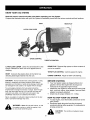
Operators Manual
CRAFI".SHAN+
I
H.P.
SOFT TOP SYSTEM AND CART
Model No. 486.24504
•
•
•
•
•
CAUTION:
Before using this product, read
this manual and follow all
Safety Rules and
Operating
Instructions.
IMPORTANT
- READ
THIS
For Missing Parts or Assembly
Please Call 217-728-8388
Safety
Assembly
Operation
Maintenance
Parts
FIRST!!!
Questions
Mon.-Fri. 7 am - 5 pm CST.
FAX 217-728-2032
or e-mail [email protected]
Missing parts will be sent UPS in 24 hours directly to your home.
Sears, Roebuck and Co.,
www.sears.com/craftsman
PRINTED IN U.S.A.
Hoffman
Estates,
IL 60179
U.S.A.
FORM NO. 48796 (2/03)
WARRANTY ...............................................................
2
SAFETY RULES ........................................................
3
ACCESSORIES AND ATTACHMENTS
................... 5
FULL SIZE HARDWARE CHART ............................. 6
CARTON CONTENTS ............................................... 8
ASSEMBLY ................................................................
9
OPERATION ............................................................
18
MAINTENANCE .......................................................
20
STORAGE ................................................................
21
TROUBLESHOOTING
............................................. 21
REPAIR PARTS ILLUSTRATIONS
............ 22,23,24
REPAIR PARTS LISTS ................................ 22,23,25
SLOPE GUIDE .........................................................
27
PARTS ORDERING/SERVICE
............... Rear Cover
LIMITED WARRANTY ON CRAFTSMAN POWERED TRACTOR ATTACHMENTS
For one (1) year from the date of purchase, if this Craftsman Equipment is maintained, lubricated and tuned up
according to the instructions in the owner's manual, Sears will repair or replace free of charge any parts found to be
defective in material or workmanship. Warranty service is available free of charge by returning your Craftsman
equipment to your nearest Sears Service Center. In-home warranty service is available but a trip charge will apply.
This Warranty applies only while this product is in the United States.
This Warranty does not cover:
Expendable items which become worn during normal use, such as spark plugs, air cleaners, belts, and oil filters.
Tire replacement or repair caused by punctures from outside objects, such as nails, thorns, stumps, or glass.
Repairs necessary because of operator abuse, including but not limited to, damage caused by impacting objects
that bend the frame or crankshaft, or over-speeding the engine.
Repairs necessary because of operator negligence, including but not limited to, electrical and mechanical
damage caused by improper storage, failure to use the proper grade and amount of engine oil, or failure to
maintain the equipment according to the instructions contained in the owner's manual.
Engine (fuel system) cleaning or repairs caused by fuel determined to be contaminated or oxidized (stale). In
general, fuel should be used within 30 days of its purchase date.
Equipment used for commercial or rental purposes.
LIMITED WARRANTY ON BATTERY
For ninety (90) days from date of purchase, if any battery included with the equipment proves defective in material
or workmanship and our testing determines the battery will not hold a charge, Sears will replace the battery at no
charge. Warranty service is available free of charge by returning your Craftsman equipment to your nearest Sears
Service Center. In-home warranty service is available but a trip charge will apply. This Warranty applies only while
this product is in the United States.
TO LOCATE THE NEAREST SEARS SERVICE CENTER OR TO SCHEDULE
SIMPLY CONTACT SEARS AT 1-800-4-MY-HOME.
SERVICE,
This warranty gives you specific legal rights, and you may also have other rights, which vary from state to state.
2
Any powerequipment
cancauseinjuryif operatedimproperlyor if the userdoesnot understandhowto operatethe
equipment.
Exercisecautionatall times,whenusingpowerequipment.
• Readandfollowall instructions
in this manualbefore
attempting
toassemble
oroperate
thisequipment.
Failure
to complywiththeseinstructions
mayresultin personal
injury.Keepthismanual
inasafeplaceforfuturereference
andfororderingreplacement
parts.
• Readthisoperating
andservice
instruction
manual
carefully.
Bethoroughly
familiarwiththecontrols
andproperuseof
thispowervacuum.
• Readthevehicle
owners
manual
andvehiclesafeoperation
rulesbeforeusingthisequipment.
• Neverallowchildren
under16tooperate
thisVacSystem.
Children16yearsandoldershouldonlyoperateunder
closeparental
supervision.
• Donotallowanyoneto operatethisequipment
without
properinstructions.
• Donotallowpassengers
torideonthisequipment
oronthe
towingvehicle.
• Keeptheareaofoperation
clearofallpersons,
particularly
smallchildren.
Alsokeepareaclearofpets.
• Checkfuelbeforestartingengine.Donotfill fuel tank
indoors,
orwhenengineisrunning,
orwhileengineis hot.
Wipeoffanyspilledfuelbeforestartingengine.
• Engineandmufflerget hot.Donottouch!To avoidfire
hazard,
keepcleanofdebrisandotheraccumulations.
• NeverstoreVacSystem
withfuelintank.Allowengineto
coolbeforestoringinanyenclosure.
• Donotchange
enginegovernor
settings.
• Donotoperateengineif aircleaneror coveris removed,
except
foradjustment.
Removal
ofthesepartscouldcreate
afirehazard.
• Keephands,feet,face,longhairandclothingoutofinlet
anddischarge
area.ThereareROTATING
BLADES
inside
theseopenings.
• Beforecleaning,
repairing
or inspecting,
makecertainall
movingpartscometoa complete
stop.Disconnect
spark
plugwireandkeepwireawayfromplugtoprevent
accidental starting.
Keepthrottlecontrolleverinstopposition.
• IftheVacSystem
should
become
blocked
withdebrisatany
point,shutengine
offandwaituntiltheimpeller
comestoa
complete
stopbeforeattempting
toremove
theobstruction.
Disconnect
sparkplugwiretoprevent
accidental
starting.
,_
Look for
this is
symbol
to point out important
Your
safety
involved.
DANGER: This
this manual. As
tor can result in
objects. Failure
safety
• Ifthecuttingmechanism
strikesa foreignobject,orifyour
VacSystemshouldstartto vibrateabnormally,
stopthe
engineimmediately,
disconnect
thesparkplugwireand
movethewireawayfromthesparkplug.Allowthemachine
tostopandtakethefollowing
steps.
a. Inspect
fordamage.
b. Repairorreplaceanydamaged
parts.
c. Checkforloosepartsandtightentoassure
continued
safeoperation.
• Checkall boltsfortightness
atfrequentintervals
to help
insuresafeoperation.
• Checktopcoverfrequently
forwear.Replace
if wornor
damaged.
• NeveroperateVacSystemunlessdeckadapter,hose,
hoseadapter(nozzle),
discharge
chute(elbow),andtop
coverareproperly
attached
intheirplace.
• Donotremove
topcoveror attempt
toemptycontents
of
cartwhileengineisrunning.
• Never
attempt
tochange
hoseadapter
(nozzle)
ortoinstall
remotehoseattachment
whenengineis running.
• Keepallshieldsandguards(e.g.discharge
chute(elbow)
andhoseadapter(nozzle)
inplaceandsecurely
attached.
• Always
wearsafetyglasses
orothersuitable
eyeprotection
whenoperating
or maintaining
thisequipment.
• Donotstandbehindcartinexhaust
discharge
areawhile
engineis running.
• Donotoperatethisequipment
whileintoxicated
or while
takingdrugsor medication
thatimpairsthesensesand
reactions.
• Whenusingthisequipment,
startwiththevehicle
transmissioninfirst(low)gearandthengradually
increase
speed
onlyasconditions
permit.
• Operate
thisequipment
atreduced
speedonroughterrain,
alongcreeksandditchesandonslopestoprevent
tipping
orlossofcontrol.Donotdrivetooclosetoacreekor ditch.
• Vehiclebraking
andstabilityareaffected
bytheaddition
of
thisequipment.
DonotfilltheVacSystem
toitsfullcapacity
withoutchecking
thecapability
of thetowingvehicleto
safelypullandstopwiththeVacSystem
attached.
• Before
operating
onanygrade(hill)refertothesafetyrules
inthevehicle
owner's
manual
concerning
safeoperation
on
slopes.AlsorefertotheSLOPE
GUIDE
onpage27ofthis
owner'smanual.
Donotoperate
onslopesinexcess
of 10
degrees.
STAYOFFSTEEP
SLOPES.
• Follow
themaintenance
instructions
outlined
inthismanual.
precautions.
It means--Attention!!
Become
alert!!
Vac System was built to be operated according to the rules for safe operation in
with any type of power equipment, carelessness or error on the part of the operaserious injury. This unit is capable of amputating fingers and hands and throwing
to observe the following safety instructions could result in serious injury or death.
TO AVOID SERIOUS INJURY
•
•
•
•
•
•
•
•
•
•
•
•
•
Read Owner's Manual and all safety labels on machine before starting and using machine.
Do Not remove top cover or attempt to empty contents of cart while engine is running.
Do Not stand behind cart in exhaust discharge area while engine is running.
Keep hands, feet, face, long hair and clothing out of chipper inlet, vac inlet, and discharge
area. There are ROTATING BLADES inside these openings.
Wear approved safety glasses and gloves. Avoid loose fitting clothes.
Keep the area of operation clear of all persons, particularly small children and pets.
Keep all shields and guards (e.g. upper chipper chute extension, discharge chute, nozzle
assembly) in place and securely attached.
Check discharge boot frequently
for wear. Replace if worn or damaged.
If unit becomes clogged or jammed, shut off engine right away. Do Not attempt to clear
clog or jam with engine running.
Muffler and engine get hot and can cause burns. Do Not Touch. To avoid a fire hazard,
keep leaves, grass and other combustible
debris off hot muffler and engine.
Do Not attempt to remove or attach vac nozzle or optional Hose Kit with engine running.
Do Not operate unit unless nozzle or optional Hose Kit is secured in place.
Do Not fill gas tank while engine is running. Allow engine to cool at least 2 minutes
before refueling.
MUFFLER & ADJACENT
MAY EXCEED 150 o F
AREAS
WARNING
This unit is equipped with an internal combustion engine and should not be used on or near unimproved forest-covered,
or grass-covered land unless the engine's exhaust system is equipped with a spark arrester meeting applicable local or
state laws (if any). If a spark arrester is used, it should be maintained in effective working order by the operator.
In the State of California the above is required by law (Section 4442 of the California Public Resources Code). Other
states may have similar laws. Federal laws apply on federal lands. A spark arrester muffler is available at your nearest
engine authorized service center.
4
These accessories were available when the unit was purchased. They are also available at most Sears retail
outlets and service centers. Most Sears stores can order repair parts for you when you provide the model
numbers of your tractor and Vac System.
I
\
The Hand Wand Attachment, Model 486.24509
provides a 15' x 5" diameter hose to clean
around shrubs, patios, window wells and other
areas not accessible to the tractor.
The model and serial numbers wilt be found on a decal
attached to the engine base.
You should record both the serial number and the date of
purchase and keep in a safe place for future reference.
MODEL NUMBER:
SERIAL NUMBER:
DATE OF PURCHASE:
486.24504
SHOWN
FULL SIZE
A
N
J
\
jT
W
jU
X
J
Y
BB
_J
I
I
I
NOT SHOWN
FULL SIZE
DD
CC
6
J
EE
J
ATTENTION!
Keep contents
of each hardware
CONTENTS
Ref. Qty.
A
B
C
D
E
H
J
K
L
M
N
O
3
2
1
2
4
25
4
12
2
4
3
2
package
OF LARGE VAC HARDWARE
Description
Ref.
Qty.
Bolt, Hex 3/8" x 3"
Shoulder Bolt
Hex Bolt, 1/2" x 1-1/4"
Bolt, Hex 1/4" x 1-3/4"
Hex Bolt, 1/4" x 1-1/4"
Bolt, Hex 1/4" x 5/8"
Hex Bolt, 5/16" x 3/4" Thread Forming
Bolt, Truss Head 5/16" x 3/4"
Bolt, Curved Head 1/4" x 1"
Lock Washer, 5/16"
Lock Washer, 3/8"
Flat Washer, 1/4"
P
Q
R
W
T
U
V
X
Y
Z
AA
BB
4
2
1
4
29
4
12
4
5
1
2
1
CONTENTS
separate
OF SMALL
DECK ADAPTER
Qty.
F
G
I
O
P
Q
U
W
CC
DD
EE
2
3
2
3
5
12
4
4
1
1
1
Description
Hex Bolt, 5/16" x 1"
Hex Bolt, 1/4" x 3/4"
Carriage Bolt, 5/16" x 3/4"
Flat Washer, 1/4"
Nylon Washer
Flat Washer, 5/16"
Hex Lock Nut, 1/4"
Hex Lock Nut, 5/16"
Mounting Strap
Angle Bracket
Mounting Bracket
assembly.
PACKAGE
Description
Nylon Washer
Flat Washer, 5/16"
Flat Washer, 7/16"
Flat Washer, 1"
Hex Nut, 1/4" (SEMS)
Hex Lock Nut, 1/4"
Hex Nut, 5/16" (SEMS)
Nylock Nut, 5/16"
Nut, Hex Lock 3/8"
Hex Lock Nut, 1/2"
Pin, Cotter 1/8" x 1-1/2"
Hair Cotter Pin, 1/8"
HARDWARE
Not all parts in this bag will be used.
Ref.
for easier
PACKAGE
6
J
jl
3
J
10
11
_18
19
j21
22
J
33
_29
CARTON
25
31
CONTENTS
Ref.
Qty.
Description
1
2
3
4
5
6
7
8
9
10
11
12
13
14
1
2
2
2
1
2
1
1
1
1
2
1
2
2
Cover
Top Connecting Tube
Support Tube, R.H.
Support Tube, L.H.
Elbow (Discharge Chute)
Deck Adapter
Hose
Hose Hanger Rod Assembly
Hose Adapter (Nozzle)
Engine
Hose Clamps
Tailgate
Cart Bodies
Wheels
15
16
1
1
Tailgate Reinforcement
Wheel Support
Bracket
8
Ref.
Qty.
17
18
19
20
21
22
23
24
25
26
27
28
29
30
31
32
33
1
1
1
1
1
1
1
1
1
2
1
1
1
1
1
2
2
Description
Latch Stand Bracket
Front Panel
Axle
Front Tongue
Rear Tongue
Hose Hanger Bracket
Hitch Plate
Hitch Pin
Rubber Strap
Tailgate Guide
Front Tube Support Bracket,
Front Tube Support Bracket,
Rear Tube Support Bracket,
Rear Tube Support Bracket,
Deck Adapter Bracket
Hub Caps
Wheel Spacers
R.H.
L.H.
L.H.
R.H.
Thisunitis shippedWITHOUT
GASOLINE
or OIL. After
assembly,
seeseparateenginemanualforproperfuel
andengineoilrecommendations.
TOOLS
REQUIRED
FOR ASSEMBLY
(1)
(1)
(1)
(2)
(2)
(2)
Screwdriver
Pliers
3/8" Wrench
7/16" Wrenches
1/2" Wrenches
9/16" Wrenches
(1)
3/4" Wrench - (2) if hitch plate in fig. 21 is used
REMOVAL
•
•
•
5116"x 3/4" TRUSS
HEAD BOLT
OF PARTS
FROM
/
CARTONS
Remove the hardware packs and all loose parts from
the cartons.
Lay out and identify parts shown in carton contents.
Lay out and identify parts in the hardware packs.
Keep contents of each hardware package separate
for easier assembly.
ASSEMBLING
•
Fit the tailgate reinforcement bracket around the end
of the cart body.
Fasten the tailgate reinforcement bracket to the
bottom of the cart body using four 5/16" x 3/4" truss
head bolts and 5/16" (SEMS) hex nuts as shown in
figure 2. Do not tighten yet.
©
/
_/@
TAILGATE
REINFORCEMENT
BRACKET
_16"(SEMS)
HEXNUT
THE VAC SYSTEM
Place cart body halves upright on a smooth level
surface such as a garage floor or a paved driveway.
See figure 1.
FIGURE 2
CAUTION: Do not leave the cart unattended in
upright position during assembly. A falling cart
can cause personal injury! Pay close attention
to the stability of the cart while it remains in an
upright position. For best stability, assemble on
a smooth level surface.
•
/
•
•
Assemble cart body halves together using three 1/4"
x 5/8" hex bolts and 1/4" (SEMS) hex nuts as shown
in figure 1. Do not tighten yet.
•
Assemble the L.H. Rear Tube Support Bracket to the
top flange of the cart using a 1/4" x 5/8" hex bolt and
1/4" SEMS hex nut. Do not tighten yet. See figure 3.
Fasten a Tailgate Guide to the Tube Support Bracket
and the side of the cart using three 1/4" x 5/8" hex
bolts, a 5/16" washer and three 1/4" SEMS hex nuts.
Place the washer on the bottom hole between the
Tailgate Guide and the side of the cart. Do not
tighten yet. See figure 3.
Repeat for other side of cart.
1/4" x 5/8" HEX BOLT
1/4" (SEMS) HEX NUT
5/16" STD
WASHER
L.H. REAR TUBE
SUPPORT BRACKET
1/4" (SEMS)
HEX NUT
1/4" x 5/8"
HEX BOLT
1/4" (SEMS)
HEX NUT
X
TAILGATE GUIDE
114"x 5/8"
BOLT
FIGURE 1
FIGURE 3
9
Lay the cart down onto it's top flanges.
Align the latch stand bracket so that the tab is at the
rear. Fasten the bracket to the rear set of holes at
the front of the cart, leaving the front holes empty for
now. Use two 1/4" x 5/8" hex bolts, 1/4" flat washers
and 1/4" (SEMS) hex nuts. Use the 1/4" flat washers
as shims between the bracket and the cart bed.
Make only finger tight at this time. See figure 5.
• Pullthecartbodyhalvestogether.
• Tightenthefourtrussheadbolts.
Tightenthesixhexboltsinthesidesofthecart.
Tightenthethreehexboltsinthe bottomofthecart,
keepingthebottomaligned.
Assemblethewheelsupporttothe bottomofthecart
usingeight5/16"x 3/4"trussheadboltsand5/16"
(SEMS)hexnutsasshownin figure4. Headsof bolts
goonthe insideofcart.Tighten.
LATCH STAND
BRACKET
r/
5/16" (SEMS)
HEX NUT
1/4" (SEMS)
HEX NUT
,/
®
1/4" FLAT
5/16" x 3/4"
TRUSS HEAD BOLT
/
\
1/4" x 5/8"
HEX BOLT
FIGURE 5
Place the rear tongue onto the wheel support and the
latch stand bracket. Assemble the axle through the
wheel support and the tongue. Fasten the axle to the
wheel support using two 1/4" x 1-3/4" Hex Bolts and
1/4" (SEMS) Hex Nuts. See Figure 6.
WHEEL
SUPPORT
FIGURE 4
IMPORTANT:
Make sure the tongue is securely locked
to the latch stand bracket by the latch lock lever.
1/4" x 1-314"
HEX BOLT
AXLE
TONGUE
(REAR)
LOCK
LEVER
1/4" (SEMS)
HEX NUT
FIGURE 6
10
Assemblea spacertubeontoeachendof theaxleas
shownin figure7.
Assemblea 1"flatwasher,a wheel(valvestem
facingout),andanother1"flatwasherontotheaxle
as shownin figure7.Securethewheelwitha 1/8"x
1-1/2"cotterpin,spreadingtheendssothata hub
capwiltfit overthepin.Assemblethehubcapby
pressingitontotheflatwasher.Repeatonotherend
of axle.
Release the latch lock lever and tilt the cart bed
back. See figure 9.
Assemble the front panel to the cart, sliding the
bottom lip of the panel between the cart and the latch
stand bracket. Secure with six 1/4" x 5/8" hex bolts
and 1/4" SEMS hex nuts. Leave the upper holes on
the sides empty. Do not tighten yet. See figure 9.
FRONT
1/4" x 5/8"
HEX BOLT
SPACER TUBE
WHEEL
AXLE
\
1" FLAT
WASHER
LEA VE THESE
HOL E_
_'_
\
\
\\
\
1/4"
T
HUB CAP
PANEL
1"FLAT
WASHER
1/8" x 1-112"
COTTER PIN
FIGURE 7
FIGURE 9
•
•
Flip the cart over so that it rests on its wheels.
Assemble the front tongue on top of the rear tongue
using three 3/8" x 3" hex bolts, 3/8" lock washers and
3/8" hex lock nuts. See figure 8.
HINT: For easier assembly, support the rear tongue with
a block of wood.
• Assemble the hitch pin to the hitch bracket and
tongue, securing it with the 1/8" hair cotter pin. See
figure 8.
•
•
•
Place the R.H. Front Tube Support Bracket under the
top flanges of the cart, as shown in figure 10. Fasten
the bracket to the cart using three 1/4" x 5/8" hex
bolts and 1/4" SEMS hex nuts. Do not tighten yet.
Repeat for the L.H. Front Tube Support Bracket.
Tighten all loose bolts and nuts.
1/4" x 5/8"
HITCH PIN
3/8" x 3"
%
TONGUE
(FRONT)
\
\
SUPPORT BRACKET
!
3/8" LOCK
WASHER
:'
318"REX \
LOCK NUT--
BLOCK
1/8" HAIR
COTTER PIN
FIGURE 8
FIGURE 10
11
1/4" (SEMS)
HEX NUT
AssemblethereducedendsoftheR.H.support
tubesintotheendsoftheL.H.supporttubes.Fasten
thetubestogetherusingtwo1/4"x 1"curvedhead
bolts,insertedfromthetop,andtwo1/4"(SEMS)hex
nuts.Seefigure11.
To install the fabric cart cover:
1. Unzip the cover's rear flap and place the cover on
top of the support tubes, making sure that the
zippered flap is at the rear of the cart.
2. Pull the front of the cover down over the front
support tubes and hook the cover's plastic channel
under the cart's front flange.
3. Pull the sides of the cover down and hook the
1/4" x 1" CURVED
HEAD BOLT
"_
cover's plastic channel under the cart's side
flanges.
4. Swing the rear flap up onto the top of the cover.
Starting at the top, secure the cover to the rear
support tubes with the three velcro straps on each
side. Tighten the straps so that the zipper is pulled
around behind the support tubes. The zipper
should close easily.
5. Unzip the rear flap to place the tailgate down into
the tailgate guides. See Figure 13.
I
/
1/4" HEX
NUT (SEMS)
SUPPORT
TUBE R.H.
SUPPORT
TUBE L.H.
FIGURE 11
Place the support tubes down into the front and rear
tube support brackets, with the tube's welded brackets facing the center of the cart.
Assemble the top connecting tubes to the support
tubes using four 1/4" x 1-1/4" hex bolts and 1/4" hex
lock nuts. Tighten only until there is no end play in
bolt. Tubing should fold up when removed from cart.
See Figure 12.
1_" x 1-1_"
HEX BOLT
\
1_" HEX
LOCK NUT
Plasti_
Channel
FIGURE 13
CONNECTING
/TUBE
FIGURE 12
12
•
Remove the hex bolts, lock washers and hex lock
nuts from the two holes in the impeller housing as
shown in figure 16. Assemble the hose hanger
bracket to the two holes using the bolts, lock washers
and lock nuts which you removed.
Assemble a plastic wheel to each engine mount
bracket using a 3/8" shoulder bolt and 3/8" hex lock
nut. See Figure 14.
USE THESE
HOLES
HOSE
HANGER
3/8"SHOULDER
USE PREASSEMBLED
LOCK
fWASHERS AND
G HEX LOCK
NUTS
FIGURE16
FIGURE 14
•
Attach the vac tongue to your tractor's draw bar for
easier mounting of the engine base assembly.
Align the engine base with the tongue's welded
angles. Tilt the engine base back on it's wheels so
that the ends of the mount brackets rest on the
tongue, underneath the welded angles. Lift up on
the engine base and slide the engine mount brackets
underneath the welded angles. Fasten the mount
brackets to the welded angles using four 5/16" x 1"
hex bolts, 5/16" lock washers and 5/16" nylock nuts.
Tighten the bolts securely. See figure 15.
•
Assemble the elbow to the impeller housing using
four 5/16" x 3/4" thread forming bolts and four nylon
washers. Push while turning to help start the bolts
into the unthreaded holes. Tighten. See figure 17.
If the elbow does not align with the cover opening:
Step I Loosen the four bolts shown and adjust the
position of the engine base. Retighten the bolts.
Step2
Loosen (about 1/4 turn) the four bolts
shown. Push against the elbow to center it in the
opening. Retighten the bolts.
Pull the boot onto the end of the elbow and tighten
the draw string.
ELBOW
MOUNT
BRACKET
WELDED
ANGLE
WASHER
5/16" x 3/4"
HEX BOLT
STEP 1
(Thread Forming_._
5/16" x 1=
HEX BOLT _
5/16" LOCK _
WASHER
_
_'-'-'-
5/16" NYLOCK
NUT
FIGURE 15
FIGURE 17
13
STEP 2
•
Place the hose hanger rod assembly down into the
hose hanger bracket on the impeller housing assembly. See figure 18.
•
Loop the 25" tarp strap under the hose. Fasten the
hooks to the hose hanger rod assembly. See figure
20.
HOSE HANGER
ASSEMBLY
HOSE HANGER
ASSEMBLY
25" TARP
STRAP
\
©
©
FIGURE20
FIGURE 18
•
•
Place a hose clamp onto the end of the hose. Push
the hose onto the hose adapter (nozzle). Tighten the
hose clamp onto the hose and hose adapter. Do not
collapse the hose adapter when tightening the
clamp. See figure 19.
The remaining hose clamp will be used later to fasten
the hose to the deck adapter.
•
Assemble the hitch plate to the tractor hitch if:
a. Your tractor has a square (straight) hitch frame,
to help prevent binding.
b. Your tractor has a lightweight hitch frame that
needs reinforcement for towing.
Use a 1/2" x 1-1/4" hex bolt, a 7/16" flat washer and a
1/2" hex lock nut. See figure 21.
1/2" x 1-1/4"
HEX BOLT
HOSE ADAPTER
TRACTOR
!
HITCH FRAME
Q
ATTACH
(SQUARE)
U
MOW-N-VAC
HERE
CLAMP
HOSE
HITCH
PLATE
7/16
I_"HEX
LOCK NUT
TRACTOR
HITCH FRAME _-_._
(TAPERED)
FIGURE 19
FIGURE 21
14
I
i
s_
:_-
J
--s_:
°
l/
Y
ASSEMBLING
THE #62468
TO THE MOWER DECK
Position the adapter over the deck opening, and check
for fit of cutout as shown in figure 23. Trim cutout, if
necessary, to allow tilting of adapter, keeping the fit as
close as possible for best vacuum suction.
DECK ADAPTER
NOTE: Not all of the parts in the deck adapter hardware
package will be used for any one particular fit up.
•
NOTE:
Remove the mower discharge deflector from your
mower deck. Save the deflector and hardware for
Make sure adapter clears gauge
wheels on mower deck
remounting deflector.
DECK ADAPTER
/
CAUTION:
Mower deflector must be
replaced when Vac System deck adapter is
removed. Do Not operate mower unless
adapter or deflector is in place and properly
mounted.
FITTING
TO SEARS
MOWER DECK
/
I
TRACTORS
The yellow fold out sheet contains the templates for
Sears tractors only. (The white fold out sheets include all
templates, including other tractor brands.)
/f you have a Murray brand tractor with a 38", 40" or 46"
deck, go directly to the instructions on pages 16 and 17.
Curl on deck may be located outside of
adapter or inside depending on deck
opening design
FIGURE 23
Identify and cut out the template for your brand and
size mower deck. If there is no template included for
your deck size, you can make your own template by
marking around a piece of cardboard held against the
edge of the deck's discharge opening.
•
Holding the adapter bracket and the deck adapter
together, position the deck adapter on the mower
deck. Keeping the edge of deck adapter as close as
possible to the offset in the adapter bracket, see if
the slot in the adapter bracket can be aligned with
one or two of the deflector holes in your mower
deck's discharge opening. If the bracket can not be
located correctly using existing holes, it will be
necessary to drill one or two 5/16" diameter holes in
the deck. See figure 24.
FOLLOW THE INSTRUCTIONS PRINTED ON THE
TEMPLATE. If there are no instructions, use the
following instructions as a general guide.
Tape the template to the face of the adapter, about
1/2" from front and 1/4" down from top for deeper
decks. For shallow decks, position template low
enough that adapter will not extend below bottom of
deck. Mark outline of template on face of adapter
using white crayon, nail or scriber. Drill a starting
hole inside the outline, then use a saber saw or key
hole saw to cut out the opening. See figure 22.
Use existing holes or drill 5/16"
diameter hole or holes.
ADAPTER BRACKET
1/4" MINIMUM
Cut out as close to top
edge as possible without
causing adapter to extend
below bottom of deck.
DECK ADAPTER
I_"FROM
MOWER DECK
Keep edge of adapter as close
as possible to offset in bracket
FRONT
FIGURE 22
FIGURE 24
15
•
Assemble the adapter bracket to the deck using two
5/16" x 1" hex bolts, 5/16" flat washers and 5/16" hex
lock nuts. See figure 25.
FOR 1990 AND NEWER MURRAY
WITH A 38" OR 40" DECK
NOTE: It may be necessary to use extra 5/16" flat
washers to shim under the bracket next to the deck
surface. Ten extra washers have been furnished as
shims. See figure 25.
I
(2) _16"
(_-LOCK
TRACTORS
Cut out two templates and place on deck adapter as
shown in figure 33. Tape smaller one on top and
larger one on the side and bottom. After they are in
place, carefully mark around the templates, then cut
out adapter to obtain correct opening.
Bolt end of mounting strap to the 5/16" bolt on the
mower deck. The other end of the strap will bolt to a
hole in the deck adapter, which must be drilled.
Position the adapter on the deck, then drill a 5/16"
hole in the bottom of the adapter that will align with
the hole in the strap. Fasten the adapter to the strap
using one 1/4" x 3/4" hex bolt, 1/4" flat washer, nylon
washer and 1/4" hex lock nut. See figure 27.
HEX
NUTS
5/16"FLAT
WASHERS
ADAPTER BRACKET
5/16"x1"HEXBOLT
7_
5/16" flat washers
used as needed for
shims to adjust for
variations in decks.
38"/40" TEM PLATE
TEMPLATE
TO CUT OUT SLOT
FIGURE25
With deck adapter positioned correctly over the
discharge opening, use the adapter bracket as a
template and drill three 9/32" diameter holes in the
top of the deck adapter. See figure 26.
Bolt deck adapter to bracket using three 1/4" x 3/4"
bolts, nylon washers, 1/4" flat washers and 1/4" hex
lock nuts. Nylon washers should be against the
inside of the deck adapter. See figure 26.
MOUNTING
BOLT THIS END OF
STRAP TO 5/16" BOLT
ON MOWER DECK
STRAP
1/4" LOCK NUT
DECK ADAPTER
(3) 1/4" HEX
LOCK NUTS
FIGURE27
ADAPTER
Assemble end of hose and hose clamp over the round
opening of deck adapter and tighten clamp. GO
DIRECTLYTO THE OPERATION INSTRUCTIONS
WHICH ARE LOCATED ON PAGE 18.
\
(3)NYLON
WASHERS
MOWER DECK
(3) 1/4" STEEL WASHERS
(3) 1/4" x 3/4" HEX BOLTS
FIGURE26
9. Assemble end of hose and a hose clamp over the
round opening of deck adapter and tighten clamp.
GO DIRECTLY TO THE OPERATION INSTRUCTIONS ON PAGE 18.
16
FOR 1990 AND NEWER
MURRAY
TRACTORS
WITH A 46" DECK
Tape 46" template onto deck adapter. Mark and then
cut out adapter.
Fasten the angle bracket and the mounting bracket to
the mower deck as shown in figure 34. Use two 5/16"
x 3/4" carriage bolts, 5/16" flat washers and 5/16"
lock nuts. The bolt heads go on inside of mower
deck.
Drill two 5/16" diameter holes in the deck adapter that
will align with the holes in the angle bracket and the
mounting bracket. Assemble the deck adapter to both
brackets using two 1/4" x 3/4" hex bolts, 1/4" flat
washers, nylon washers and 1/4" hex lock nuts. See
figure 28.
ANGLE BRACKET
NYLON WASHER
_1_
t \
HEXLOCKNUT
_
MOUNTING
1/4"FLAT
1/4" x 3/4
HEX BOLT _
LOCATE
AND
DRILLHOLES
\\\\
N_N
WASHER _
1/4" FLAT WASHER
1/4" x 3/4" HEX BOLT -_"-_
FIGURE28
Assemble end of hose and hose clamp over the round
opening of deck adapter and tighten clamp. GO
DIRECTLY TO THE OPERATION INSTRUCTIONS
WHICH ARE LOCATED ON PAGE 18.
17
KNOW
YOUR
VAC
SYSTEM
Read this owner's manual and safety rules before operating your Vac System.
Compare the illustration below with your Vac System to familiarize yourself with the various controls and their locations.
BOOT
\
REAR FLAP
\
\
\
\
\
LATCH LOCK LEVER
CHOKE CONTROL
\\
THROTTLE
LATCH LOCK LEVER Locks the cart bed down to the
tongue. Releases to allow cart to be tipped back for
dumping.
CONTROL
REAR FLAP Zippered
cart to be emptied.
THROTTLE
BOOT Connects the plastic elbow to the fabric top,
directing discharged material into the cart.
CHOKE CONTROL
CAUTION:
Alcohol blended fuels (called gasohol or using
ethanol or methanol) can attract moisture which leads to
separation and formation of acids during storage. Acidic gas
can damage the fuel system of an engine while in storage.
BEFORE
To avoid engine problems, the fuel system should be
emptied before storage for 30 days or longer. Drain the gas
tank, start the engine and let it run until the fuel lines and
carburetor are empty. Use fresh fuel next season. See
STORAGE Instructions for additional information.
•
Never use engine or carburetor cleaner products
tank or permanent damage may occur.
HOW
•
•
in the fuel
•
•
,_
CONTROL
the
engine running,
WARNING:
Never orfillwhile
fuel the
tank engine
indoors,is hot.
or with
Do not smoke while filling tank.
Controls
speed of engine.
Adjust to allow cold starting.
STARTING
Your Vac System engine is shipped without oil or
gasoline. Service the engine with oil and gas as
instructed in the separate engine manual.
Inspect the Vac System to make sure all covers (rear
door, vinyl boot, elbow, hose adapter, hose and deck
adapter are properly attached.
Check tires for proper inflation (12 - 14 lbs).
TO STOP
YOUR
VAC
SYSTEM
To stop engine, move the throttle control lever to the
OFF position.
Disconnect spark plug wire from plug to prevent
accidental starting while equipment is unattended or
is being worked on.
are
hot!
CAUTION:
18
flap opens to allow contents of
The muffler and adjacent areas
HOW TO START
YOUR VAC SYSTEM
,_
_,
•
•
•
•
•
•
•
without all covers being properly attached to the
ARNING:
Never start or run the engine
blower housing and cart.
•
•
Check oil and gas in Vac engine.
Attach spark plug wire to spark plug.
Move choke lever on engine to CHOKE position.
(A warm engine may not require choking.)
Move throttle control lever on engine to FAST position.
Grasp starter handle and pull rope out slowly until
engine reaches start of compression cycle (rope wilt
pull slightly harder at this point). Let the rope rewind
slowly.
Pull rope with a rapid, continuous, full arm stroke.
Keep a firm grip on starter handle. Let rope rewind
slowly. Do not let starter handle snap back against
starter.
Repeat instructions in two preceding paragraphs until
engine fires. When engine starts, move choke control
gradually to RUN position.
•
•
TO
•
•
•
that
no one is To
near
the cart
before
releasing
the
CAUTION:
avoid
possible
injury,
be sure
latch lock lever.
Remove the tailgate.
Release the latch lock lever on the tongue and tip the
cart back.
Using a rake or suitable tool, pull grass clippings and/
or leaves out of the cart.
After the cart is emptied, tip it forward and secure it
to the tongue with the latch lock lever. Install the
tailgate, place the bottom of the rear flap inside the
tailgate and zip the rear flap shut.
USE THE CART WITHOUT THE VAC SYSTEM
Unzip the rear flap and unfasten the velcro fasteners.
Remove and store the soft top cover.
Remove the tube frame in one piece and store.
are
hot!
CAUTION:
HOW TO USE YOUR
VAC SYSTEM
•
CAUTION:
Vehicle braking and stability
may be affected with the addition of an accessory or an attachment. Be aware of changing
conditions on slopes.
•
•
•
•
•
The muffler and adjacent areas
•
Inspect the Vac to make sure the cover, rear door,
boot, elbow, hose adapter (nozzle), hose and deck
adapter are properly attached.
Check tires for proper inflation (12 - 14 Ibs).
Check for oil and gas in Vac engine.
Begin operation at low speed, adjusting forward speed
to match grass height and/or moisture condition to
prevent clogging.
Do not attempt to vacuum up any material other than
vegetation found in a normal yard, such as light
branches, leaves, twigs, etc.
WARNING:
Should your Vac System
become clogged, shut off tractor and Vac
engines. Before attempting to unclog, remove
wire from spark plug to prevent accidental
starting.
TO
•
•
•
EMPTY THE CART
Shut off the tractor engine and set the brake.
Shut off the Vac engine.
Loosen the draw string and pull the boot back from
the elbow.
•
Unzip the rear flap, flip it up and secure it with the
velcro strips on top of the cover.
19
Remove and store the four bolts and nuts which
fasten the engine base to the tongue.
Slide the engine off the tongue and roll to a safe
storage area.
CUSTOMER
•
RESPONSIBILITIES
Read and follow the maintenance schedule and the maintenance procedures listed in this section.
MAINTENANCE
SCHEDULE
_e_&_
Fill in dates as you
complete
regular service.
_'___f
Check
for loose
Check
cover
fasteners
X
Check
tire pressure
X
Service Dates
X
X
per instructions
e
X
Clean
enaine
_,o_
e_-_e_
X
Check enqine oil level
Lubricate
Maintain
,_
below and in enaine
X
manual.
BEFORE
EACH USE
CHECK FOR LOOSE FASTENERS
•
WARNING:
Always stop engine and
disconnect spark plug wire before cleaning,
lubricating or before performing any repairs or
maintenance.
Make a thorough visual check of the Vac System for
any bolts and nuts which may have loosened.
Retighten any loose bolts and nuts.
ENGINE
CHECK COVER
• Check the cover, especially the front boot and the
rear flap for wear. Replace cover if worn or damaged.
Only use high quality detergent oil rated with API
service classification SF or SG. Select the oil's SAE
viscosity grade according to your expected operating
temperature. SAE 30 grade oil is recommended for
warm weather use. For cold weather use refer to the
engine manufacturer's Operating and Maintenance
Manual.
CHECK TIRE PRESSURE
•
Check tire pressure regularly. Recommended tire
pressure is 12-14 Lbs.
CHECK ENGINE OIL LEVEL
• Check oil level before each use. Maintain engine oil
as instructed in the separate engine manual.
•
•
LUBRICATION
•
•
MAINTENANCE
At the beginning of each season, lubricate the latch,
latch pivot bolt, and the axle where the hitch tongue
pivots, with a light machine oil.
At least once a season, grease or oil the wheel
bearings. Use automotive wheel bearing type grease
or 20 weight oil.
•
Check oil level before each use. Maintain engine oil
as instructed in the separate engine manual.
Service air cleaner every 25 hours under normal
conditions. Clean every few hours under extremely
dusty conditions. Poor engine performance and
flooding usually indicates that the air cleaner should
be serviced. To service the air cleaner, refer to the
separate engine manual.
The spark plug should be cleaned and the gap reset
once a season. Spark plug replacement at the start
of each season is recommended. Check the engine
manual for correct plug type and gap specifications.
CLEANING
•
•
2O
Make sure the cart and top are cleaned after each
use. Grass clippings and leaves left in the cart will
mildew and cause damage if not cleaned out.
Clean the engine regularly with a cloth or brush.
Keep the cooling fins on the engine housing clean to
permit proper air circulation which is essential to
engine performance and life. Be sure to remove all
dirt and debris from muffler area.
• Cleantheengineandtheentireunitthoroughly.
• Refertoenginemanualforcorrectenginestorage
instructions.
• If storingin anunventilated
or metalstorageshed,
coatmetalpartswithlightoilor siliconetoprevent
rust.
• Storeunitina clean,dryarea.
It is importanttopreventgumdepositsfromformingin
essentialfuelsystempartssuchasthe carburetor,fuel
filter,fuelhoseor tankduringstorage.Also,alcohol
blendedfuels(calledgasoholor usingethanolor
methanol)canattractmoisturewhichleadsto separation andformationof acidsduringstorage.Acidicgas
candamagethefuel systemof anenginewhilein
storage.
Toavoidengineproblems,thefuel systemshouldbe
emptiedbeforestorageof 30 daysor longer.Follow
the instructionsin theengine'sOperating&
MaintenanceManual.
PROBLEM
POSSIBLE
CAUSE(S)
CORRECTIVE
ACTION
Enginefailstostart
1.
2.
3.
4.
Sparkplugwiredisconnected.
Safetyswitchnotcontacted.
Fueltankempty,or stalefuel.
Fuelshut-offvalveclosed
(ifso equipped).
5. Faultysparkplug.
1.
2.
3.
4.
1. Sparkplugwireloose
2. UnitrunningonCHOKE.
3. Blockedfuellineor stalefuel.
1. Connect and tighten spark plug wire.
2. Move choke lever to OFF position.
3. Clean fuel line; fill tank with clean
fresh gasoline.
4. Disconnect fuel line at carburetor to drain
fuel tank. Refill with fresh fuel.
5. Adjust carburetor.*
6. Service air cleaner.*
Lossof power;
operationerratic.
4. Wateror dirt infuelsystem.
Carburetor out of adjustment.
6. Dirty air cleaner.
5.
Engineoverheats
Toomuchvibration
Unitdoesnot
discharge
1. Carburetor not adjusted
properly.
2. Engine oil level low.
Connect wire to spark plug.
Correctly install hose adapter nozzle.
Fill tank with clean, fresh fuel.
Open fuel shut-off valve.
5. Clean, adjust gap or replace.
1.
Adjust carburetor.*
2. Fill crankcase with proper oil.
Loose parts or damaged
impeller.
Stop engine immediately and disconnect
spark plug wire. Tighten all bolts and nuts.
Make all necessary repairs. If vibration
continues, have unit serviced by an
authorized service dealer.
1. Discharge chute (elbow)
clogged.
1. Stop engine immediately and disconnect
spark plug wire. Clean inside of housing
and discharge chute (elbow).
2. Stop engine immediately and disconnect
spark plug wire. Remove lodged object.
3. Empty cart.
2. Foreign object lodged in
impeller.
3. Vac Cart is full.
*Refer to the engine manual packed with your unit.
NOTE: For repairs beyond the minor adjustments listed above, please contact your nearest authorized service dealer.
21
REPAIR
PARTS
FOR MODEL
486.24504
CART
BODY
11
32
/
16
/
12
17
12
8
8
\
10
\
23
5 9\
i
\
13
\\
19
27
REF.
NO.
)
)
i
PART
NO.
24096
62457
23487
24497
24984
43594
43093
43601
48637
43014
43866
46978
1509-69
HA20186
43814
23490
46980
QTY.
DESCRIPTION
Cart Body
Tailgate Reinforcement Bracket
Wheel Support
Latch Stand Bracket
Axle, Wheel 1" Dia.
Wheel w/Tire, 15 x 6.00
Cotter Pin, 1/8" Dia. x 1-1/2"
Washer, Flat 1"
Spacer Tube
Hub Cap
Hex Bolt, 1/4-20 x 5/8"
Hex Nut, 1/4" (SEMS)
Hex Bolt, 1/4-20 x 1-3/4"
Spring, Extension
Truss Hd. Bolt, 5/16-18 x 3/4"
Cart Front Panel
Hex Nut, 5/16-18 (SEMS)
22
24 --_
REF.
NO.
PART
NO.
QTY.
18
19
20
21
22
23
24
25
26
27
28
29
30
31
32
33
34
35
43088
64551
64531
25010
23548
43884
43343
23504
43003
43082
47407
43574
43064
24960
24959
24982
24983
43081
2
1
1
1
2
1
1
1
3
3
1
3
1
1
1
1
1
2
DESCRIPTION
Washer, Flat 1/4"
Tongue Weldment Ass'y. (Rear)
Tongue Weldment Ass'y. (Front)
Latch Lock Lever
Tailgate Guide
Hitch Pin
Pin, Hair Cotter 1/8"
Tailgate
Lockwasher, 3/8"
Hex Lock Nut, 3/8-16 Thread
Hex Bolt, 5/16-18 x 3-3/4"
Hex Bolt, 3/8-16 x 3"
Hex Lock Nut, 5/16-18
Tube Support Bracket Front R.H.
Tube Support Bracket Front L.H.
Tube Support Bracket Rear R.H.
Tube Support Bracket Rear L.H.
Washer, Flat, 5/16"
REPAIR
REF
NO.
PART
NO.
1 629-0241A
2
24634
3
24633
4
43182
5
710-0772
6
710-1268
7
43063
8
712-0421
9
43064
10
43086
11 719-0330A
12 725-1700
PARTS FOR MODEL 486.24504
VAC SYSTEM
IMPELLER
HOUSING ASSEMBLY
QTY. DESCRIPTION
1
1
1
10
3
2
3
3
10
13
1
1
REF
NO.
PART
NO.
13
14
15
16
17
18
19
20
21
22
23
24
725-3166
726-0272
731-1613
24958
712-3046
47810
736-0247
63924
710-1273
43003
629-0923
48591
Harness, Wire
Housing Ass'y. Inner
Housing Ass'y. Outer
Bolt, Hex 5/16-18 x 3/4"
Bolt, Hex 5/16-24 x 2"
Screw, Self Tap #10-16 x 3/8"
Bolt, Hex 5/16-18 x 1"
Knob
Nut, Hex Lock 5/16-18
Washer, Lock 5/16" Spring Type
Adapter, Mounting
Cover, Switch
23
QTY. DESCRIPTION
1
1
1
1
3
2
1
1
1
1
1
2
Snap Mount Switch
Clamp
Cover, Switch
Hose Hanger Bracket
Nut, Hex Jam 5/16-18 Thd.
Nut, Hex 5/16-18 Nylock
Flat Washer, 13/32" x 1-1/4"
Impeller Assembly
Bolt, Hex 3/8-24 x 2-3/4"
Lockwasher, 3/8"
Harness Adapter
Spacer Rod
REPAIR
pARTS
FOR MODEL
486.24504
VAC SYSTEM
j_
f
J
23
\\
45
27
\
37
39
22 j
9
19
19
18
ADAPTER
#62466
J
J
8_
4O
27
12_
32
13
/
27
13 12 /
S
24
14
16
REPAIR
REF.
NO.
PART
NO.
QTY.
1
2
3
4
5
6
7
8
9
734-0973
24957
24956
43182
43063
43085
738-0373
43064
63375
2
2
1
14
6
4
2
11
1
10
11
12
13
14
15
16
17
18
19
20
21
22
23
24
25
26
27
28
29
3O
31
32
781-0635
728-3001
43012
43013
1
3
3
7
1
1
1
1
1
2
2
2
2
1
1
3
1
9
1
1
1
12
1
12_1 _0158-E1
222261
63227
46420
43792
43793
48634
64647
64648
48640
43790
43088
23540
1543-69
43351
43262
43352
43081
43830
PARTS
FOR MODEL
DESCRIPTION
486.24504
VAC SYSTEM
REF.
NO.
PART
NO.
3TY.
33
34
35
36
37
38
39
23560
4.3080
23825
23826
47630
712-0421
---
1
2
1
1
4
3
1
40
62468
1
41
42
43
44
45
46
47
23827
1509-90
43086
47810
43978
46978
43082
48796
1
4
8
6
2
2
2
1
Engine Wheel
Engine Mount Bracket
Engine Base
Bolt, Hex 5/16-18 x 3/4"
Bolt, Hex 5/16-18 x 1"
Bolt, Hex 5/16-18 x 1-1/2"
Shoulder Bolt
Nut, Hex Lock 5/16-18
Assembly, Hose Adapter (Nozzle)
(Includes items 10 and 11))
Bracket, Switch (Actuator)
Rivet, Pop 5/32"
Bolt, Hex 1/4-20 x 3/4"
Nut, Hex Lock 1/4-20 Thd.
Engine, B & S 5 HP
Deflector, Muffler
Hose Hanger Rod Ass'y.
Elbow
Hose (6" x 84")
Hose Clamp 6"
Top Connecting Tube
Support Tube, L.H.
Support Tube, R.H.
Cart Cover
Strap, Tarp 25"
Washer, 1/4" STD
Hitch Plate
Washer, Nylon 21/64"
Bolt, Hex 1/2-13 x 1-1/4"
Nut, Hex Lock 1/2-13
Washer, Flat 7/16"
Washer, 5/16" STD
Adapter, Deck
25
DESCRIPTION
Bracket, Deck Adapter
Bolt, Carr. 5/16" x 3/4"
Mounting Strap
Angle Bracket
Screw, Self Tap 5/16"-18 x 3/4"
Knob (See also Item #8, Page 23)
Impeller Housing Assembly
(See Page 23)
Deck Adapter Kit (Includes parts in
box shown on page 24)
Mounting Bracket
Bolt 1/4"-20 x 1-1/4"
Lock Washer, 5/16"
Nut, Hex 5/16-18 Nylock
Bolt, Curved Hd. 5/16-18 x 1"
Nut, Hex 1/4-20 SEMS
Nut, Hex Lock 3/8-16
Owner's Manual
26
O
e=
'o
ee=
o
O
• -, e=
;'_==
_
o_
==
|
_.=o
0
._.._o
.E_o_
,0.,., ,m =1
,,,c ,-
e-
_o, __
"r-E5
_
_
0
_o-_
CAUTION:
Do not operate
your tractor
and Vac System
on a
slope in excess of 10 degrees. Be sure of your tractor's towing and
braking capabilities before operating on a slope. Avoid any sudden
turns or maneuvers while on a slope.
Get it fixed, at your home or ours!
For repair of major brand appliances in your own home...
no matter who made it, no matter who sold it!
1-800-4-MY-HOM
EsMAnyt,me,
day or n,ght
(1-800-469-4663)
www.sears.com
To bring in products such as vacuums, lawn equipment and electronics
for repair, call for the location of your nearest Sears Parts & Repair Center.
1-800-488-1222
Anyt,me,
day or n,ght
www.sears.com
For the replacement parts, accessories and owner's manuals
that you need to do-it-yourself, call Sears PartsDirect sM!
1-800-366-PART
(1-800-366-7278)
6a.m.-
11 p.m. CST,
7 days a week
www.sears.com/partsdirect
To purchase or inquire about a Sears Service Agreement:
1-800-827-6655
7 a.m. - 5 p.m. CST, Mon.-
Para pedlr servlclo de reparaclon a domlclho,
y para ordenar plezas con entrega a domlolho:
1-888-SU-HOGAR
sM
Sat
Au Canada
pour service
(1-877-533-6937)
(1-888-784-6427)
® Registered
® Sears
Roebuck
and
Co
® Marca
Trademark
Reglstrada
,'
TH
/
Marca
en fran£ats:
1-877-LE-FOYER_M
Trademark
de Fabrlca
of Sears
de Sears
Roebuck
Roebuck
and Co
and Co