1
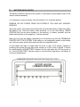
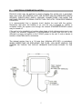
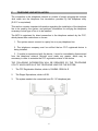
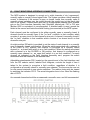
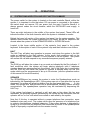
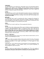
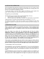
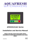
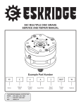
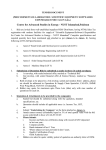
Microtel Series 100 Dialer
Installation and Operation Manual
P/N 310161 Rev B
CAUTION: Do not ship product with battery installed.
Proprietary Notice: This document and the subject matter hereto are the
property of MICROTEL, Inc. and shall not be reproduced or copied or
used for the purpose of manufacturing or sale of apparatus, except by
written permission of MICROTEL, Inc.
MICROTEL
206 West Judge Perez Drive
Chalmette, Louisiana 70043
Phone:
Fax:
504/276-0571
504/276-0574
http://www.Microtel-Inc.Com
e-mail: [email protected]
ii
MSC-100 INSTALLATION AND OPERATION MANUAL
TABLE OF CONTENTS
PAGE
I.
Introduction
A. General Information.................................................................................... 1
B. Unpacking and Incoming Inspection........................................................... 2
C. Physical System Installation.................................................................…... 3
D. Battery Installation....................................................................................... 4
E. Electrical Power Installation....................................................……………. 5
F. Telephone Line Installation......................................................................... 6
G. Fault Monitoring Interface Connections................................………………. 7
H. Powering Up the System............................................................................. 8
II.
Programming the Dialer System
A. Station Identification.......................................................………………….. 9
B. Fault Delay Time Programming…....................................………………….. 9
C. Telephone Numbers.................................................................................. 10
D. Operational Parameters .................................…………………………….. 10
1. Setting The Ring Count.....……….............................................…...... 10
2. Tone or Pulse Dial Selection..........................................................…. 11
3. Message Repetitions.......................................................................... 11
4. Intercall Delay..................................................................................... 11
5. Access Code…………….............................................................….... 11
III.
Operations
A. System Familiarization and Key Function Summary................................. 13
B. Putting the Unit in Run....……................................................................... 15
C. Receiving an Alarm................................................................................... 15
D. Remote Control Functions………………................................................... 16
E. Test and Advanced Keystroke Sequences............................................... 17
Maintenance and Troubleshooting
A. Maintenance……………............................................................................ 18
B. System Specifications............................................................................... 19
C. Product Warranty................................................................................…... 20
D. Vocabulary List…...................................................................................... 21
E. Vocabulary List Oil and Gas Industry........................................................ 22
F. Potentiometer Map……………………….................................................... 23
G. Vocabulary List Oil and Gas Industry........................................................ 24
IV.
iii
iv
I.
A.
INTRODUCTION
GENERAL INFORMATION
The purpose of this manual is to completely explain the function, installation, and
operation of the MCS Model 100. Communication System. This automatic dialing,
synthesized speech, telephone based monitoring system represents a new
generation of computer controlled telemetry devices, packed with features and
capabilities not to be found in any other telephone oriented monitoring system. The
device is designed specifically for industrial based equipment monitoring needs, by
the engineering staff, which invented the concept of synthesized speech dialers.
The MCS (Microtel Communication System) is configured to accept eight channels of
normally open or normally closed fault state switches (contacts), such as float
switches, pressure switches, temperature switches and similar devices that contain
an unpowered contact that changes state whenever a preset condition is violated.
Fault recognition can be set as fast as 1 second or as long as sixty seconds.
Internally, the system monitors its own power supply and will respond to any power
outage which lasts longer than one minute.
When an alarm occurs, recognized by the system as the opening or closing of an
external contact, it begins to place a series of telephone calls, dialing up to eight
different telephone numbers, one at a time, in an attempt to make contact with a
qualified person to whom it can deliver a synthesized verbal message, describing the
alarm condition. This message can be programmed by the user to consist of virtually
any string of individual words in response to any fault condition. The system contains
a "core" vocabulary of sixty five words, and an "application" vocabulary comprised of
a minimum of thirty two words selected for the particular application that the unit is to
be used In.
The system will continue to call from the list of up to 8 numbers, insisting that its
message be heard. Also, if desired, the system can be called at any time to check or
verify the monitored conditions. When on line with the system, telephone numbers
can be changed, delays can be changed, the system can be placed in the halt mode
or put back in run--the system can even be instructed to place a test call back to any
location just to be sure it can get through the telephone network when it needs to.
Recognizing that telephone based remote monitoring systems such as this have
typically have to share a telephone line with a telephone, the system contains a built
in speakerphone and can be placed in an unattended intercom mode for "listening in"
to the monitored location.
These instructions generally describe the installation, operation and maintenance of
the equipment. Microtel reserves the right to make engineering refinements that may
not be described herein. Any questions arising that may not be answered herein
should be directed to Microtel directly or one of our authorized sales agent for a
prompt response.
1
B.
UNPACKING AND INCOMING INSPECTION
Microtel takes all possible precautions in packaging each item to prevent shipping
damage. Carefully inspect each package at the time of receipt for signs of physical
damage. Report damage claims to the shipping agent involved immediately. Do not
install damaged equipment.
All instructions given on any attached labels or tags should be followed. Carefully
inspect all packing material before discarding it to prevent the loss of accessories,
mounting hardware, spare parts, or instructions.
If the unit is not to be installed immediately, repack it in the shipping carton to protect
it in storage.
2
C.
PHYSICAL SYSTEM INSTALLATION
Mount the system on a wall or other vertical surface, away from and protected from
harsh weather extremes. It is also recommended that the unit not be placed in close
proximity to high voltage (480 V and higher) electrical equipment. Four mounting
holes on the left and right side enclosure flanges are to be used for system mounting.
It is recommended that the system be mounted approximately 5 feet above surface
grade for proper microphone reception in both the speakerphone and intercom mode.
There are three access holes on the bottom of the unit. The left side port is for power
connection to 120 vac. The middle port is for the system's telephone line connection,
and the right side port is intended to be used for the entry of fault monitoring channel
conductors. There is an additional hole in the bottom of the unit, into which the
speakerphone microphone is mounted.
The following figure shows the recommended dimensions to be used in the physical
Installation of the system.
3
D.
BATTERY INSTALLATION
The battery installs at the top of the system, in the battery tray provided as part of the
interior chassis assembly.
It is necessary to remove power from the system if it is currently applied.
REMOVE 120 VAC POWER FROM THE SYSTEM IF YOU HAVE NOT ALREADY
DONE SO
Open the system front panel and retrieve the red and black battery leads from within
the battery tray. Push the battery lead terminals on to the new battery, BEING
CERTAIN that the red lead connects to the positive (+) battery terminal, and the
black lead connects to the negative (-) battery terminal.
Slide (do not force) the battery completely into the battery tray with the TERMINALS
POINTED INTO THE SYSTEM. If the battery is not completely seated in the battery
tray, the front panel will be obstructed and will not completely close.
A new battery will take no longer than 24 hours to gain a full charge, capable of
powering the system through any power outage up to four hours in length. It should
be noted that the LOW BATTERY indicator is only valid when the 120 vac power is
on. If the LOW BATTERY indicator stays on for more than eight hours, the battery is
in need of replacement.
4
E.
ELECTRICAL POWER INSTALLATION
Electrical power may be applied by simply plugging the system into a grounded,
three wire outlet. BE CERTAIN THAT THE OUTLET HAS AN ADEQUATE EARTH
GROUND. INSUFFICIENT EARTH GROUND CONNECTIONS CAN HARM THE
UNIT AND PREVENT INTERNAL PROTECTION CIRCUITRY FROM PERFORMING
PROPERLY.
It is recommended that a separate circuit breaker be used with the system.
Remember that when the breaker is on, and the unit is plugged in, 120vac is
contained within the system even though the internal STANDBY/OPERATE switch
may be turned off.
If the unit is to be installed in a location where large or high voltage motors are in use
a power line transient suppressor is recommended to insure that the unit is not
affected by surges and spikes in the 120VAC power to the unit. If such a device is
needed, contact Microtel for assistance.
The internal system fuse is a 1/4 amp fuse (Littlefuse #312.250), or equivalent.
WHEN INSPECTING OR REPLACING THE FUSE, YOU MUST UNPLUG THE
SYSTEM OR THROW THE CIRCUIT BREAKER SUPPLYING POWER TO THE
UNIT.
5
F.
TELEPHONE LINE INSTALLATION
The connection to the telephone network is a matter of simply plugging the modular
Jack cable into the telephone line termination provided by the telephone utility
(RJ11C or equivalent).
This section contains important information regarding the installation of the telephone
line to be used by the system, and pertinent information for notifying the telephone
company of what type of line is to be installed.
The MCS is registered for direct connection to the telephone network by the FCC,
which places three restrictions on its use:
1. The system cannot connect to a party line or a pay telephone line.
2. The telephone company must be notified that an FCC registered device is
being installed.
3. If trouble is experienced with the device, it must be immediately disconnected
from the telephone network. Microtel must make any repairs, which may be
necessary in order to maintain the FCC registration status of the device.
THE FOLLOWING INFORMATION WILL BE REQUIRED BY THE TELEPHONE
UTILITY WHICH INSTALLS THE TELEPHONE LINE FOR THE SYSTEM:
1.
The FCC Registration Number, which is, D4J6M6-13598-AL-E.
2.
The Ringer Equivalence, which is 0.2B.
3.
The system needs to be connected to an RJ-11C telephone jack.
6
G.
FAULT MONITORING INTERFACE CONNECTIONS
The MCS system is designed to accept up to eight channels of dry (unpowered),
normally open or normally closed signal lines. The system provides a small sampling
current to determine if the contact is open or closed. Leads from normally open or
normally closed switches may be routed through the conduit port at the lower right
side of the system. Connect each wire pair to its appropriate channel input terminal
pair on the Fault Interface Assembly card. Shielded, twisted pair, F20 or F22 wire
(Belden 8205 or equivalent) is recommended. If shielded cable is used, ground the
shield at the sensor and leave the shield floating (unconnected) at the MCS system.
Each channel must be configured to be either normally open or normally closed. A
channel should be normally open if the "no fault" condition is that condition which
consists of an open circuit on that channel's wire pair. A channel is normally closed if
the "no fault" condition is that condition which consists of an closed circuit on that
channel's wire pair.
An eight-position DIPswitch is provided to set the state of each channel to a normally
open or normally closed configuration. When the switch associated with a channel is
in the OPEN or OFF position, that channel is configured as a normally closed
channel i.e., a closed fault switch is a no fault condition. When the switch associated
with a channel is in the CLOSED or ON position, that channel is configured as a
normally open channel i.e., an open fault switch is a no fault condition. For each
channel, as indicated on the Fault Interface Assembly card, program the switch
associated with that channel to the desired state.
Adjustable potentiometer R35, located on the opposite end of the fault interface card
from the DIP selector switch, labeled Fault Integrate, controls the length of time it
takes for the system to recognize a fault condition, regardless of whether it is
configured as a normally closed or normally open channel. The time may be user set
for one second minimum to one minute maximum. The relative timing may be viewed
by watching the indicator CR13. The actual integration time is four times the flashing
rate of CR13.
Any unused channels should be programmed a normally open, and left unconnected.
.
7
H.
POWERING UP THE SYSTEM
NOTE: IF THE UNIT ABOUT TO BE POWERED UP FOR THE FIRST TIME
CONTAINS
HARDWARE
FOR
OPTIONAL
FEATURES,
READ
THE
SUPPLEMENTARY INSTRUCTION MANUAL FOR THOSE FEATURES BEFORE
POWERING THE UNIT UP FOR THE FIRST TIME.
After the system has been mounted in a suitable area, the battery installed and
power, telephone and fault sensing lines connected, it may be powered up by
switching the "STANDBY - OPERATE" switch in the OPERATE position. This switch
is on the main printed circuit board inside the chassis and can be found by opening
the front panel of the metal chassis. When the unit is powered up, the front panel
indicators will flash in sequence for a few moments and the system will then say
"system ready". If this does not happen, turn the switch to the STANDBY position
and disconnect power and the telephone line from the unit. Contact qualified service
personnel or Microtel for instructions or repair.
8
II.
PROGRAMMING THE DIALER SYSTEM
For this section, be advised that the keystroke entries are CAPITALIZED and the
system's response whether visual or audible, is enclosed with in [brackets].
The system must be in the Halt mode to accept programming Information. If it is not in
the Halt mode, depress the HALT key to force that condition. ["system ready"]
A.
STATION IDENTIFICATION
There are two ways to enter a station identification message into the system. The
station can be identified as a number up to eight digits in length, in which case the
system will refer to itself as, "this is station XX...X". Alternatively, the system will allow
the entry of up to sixteen words from either the "core" vocabulary, the "application"
vocabulary, or both, to be connected together into one identification message. For
instance, the station identification "This is the east plant" is comprised of five words
from the system's vocabulary. The first case is called the Number Mode, while the
later is referred to as the Message Mode of station identification entry.
*
Number Mode Entry of Station Identification
1.
ENTER, 0 ["station number, ready"]
2.
Enter desired digits, terminate the entire entry with a second
depression of ENTER ["the station number is xx...x"]
To read this data,
READ,0 ["the station number is xx...x"]
*
Message Mode Entry of Station Identification
1.
ENTER, MESSAGE,0 ["station identification, ready"]
2.
Enter desired words by entering the appropriate three digit codes for
each word in sequence from the core or application vocabulary lists found in the
appendix
3.
Terminate the entry sequence with a second depression of ENTER
["the station identification is ...(word1), (word2), (word3)...(word 16)"]
To read this data,
READ, MESSAGE, 0 ["the station identification is ...(word1), (word2),
(word3)...(word 16)"]
B.
FAULT DELAY TIME PROGRAMMING
The system allows the user to program sentences up to eight words in length to be
spoken by the system identifying each fault condition. The unit is shipped with nonspecific phrases already programmed in. The system will articulate the channels as
"fault 1, fault 2.... fault 8". The programming example below illustrates the message
string programming for channel number 1. This programming operation may be used
for all channels, which are to be used by the system, or the pre-programmed phrases
may be used for any or all of the messages. The following example illustrates the
programming procedure for fault channel 1:
9
1.
ENTER, MESSAGE, 1 ["message 1, ready"]
2.
Enter the desired three digit word addresses from core or application
vocabulary lists found in the appendix (each word selected will be spoken by the unit
following its three digit entry).
3.
Terminate entry sequence with a second depression of ENTER
To read this data,
READ, MESSAGE, 1 ["message 1 is... (word1), (word2),(word3)...(word s"]
Status only Channel Programming
Any fault channel may be programmed as a "status only" channel (i.e. it will not cause
call-outs to begin, but will be reported in any status messages). To program a channel
as a "status only" channel, program the word "tone" from the core vocabulary list as
the first word in the fault message for that channel. The unit will make a "beep" sound
after the 3-digit code for "tone" is entered. The remaining seven words identifying that
channel may then be entered as in the examples above.
C.
TELEPHONE NUMBERS
The system can be programmed with up to eight telephone numbers, which will be
called sequentially when an abnormal condition is detected by the system on any
fault channel not programmed as a "status only" channel. The example below
illustrates the telephone number programming procedure for telephone number 1.
This programming operation may be performed for all telephone number positions,
which are to be used by the system.
1.
ENTER,1 ["telephone number 1, ready"]
2.
Enter the desired phone number by depressing the numbers on the keypad.
The unit will repeat each number as you depress it. 3. Terminate the entry with a
second depression of ENTER ["telephone number 1 is nnn...n"]
To read this data,
READ, 1 ["telephone number 1 is ...nnn...n"]
Up to 16 digits may be entered for each phone number position. If any of the
numbers the unit is to call require a pause for a second dial tone, enter the pause by
using the DELAY key in place of a numeral.
To clear a phone number out of the unit, enter a 0 (zero) as the phone number. The
unit ignores any phone number that starts with a 0. If you wish to have the unit call
the Operator, enter the phone number as DELAY, 0.
D.
OPERATIONAL PARAMETERS
This section describes the procedure for setting 5 operational parameters. The first
two parameters require the setting of an option switch (DIP switch) on the inside of
the unit. This switch is on the middle of the right hand edge of the main printed circuit
board, as illustrated on the figure below.
1.
Setting the Ring Count
10
The ring count is the number of rings the unit will wait before answering a call placed
to it. This may be set to either 2 rings or to 8 rings. Perform this selection by setting
position 1 on the option switch to the OPEN (or "off") position for 2 rings and the
CLOSED (or "on") position for 8 ring selection.
2.
Tone or Pulse Dial selection
The system needs to be set for pulse or tone type dialing. Perform this selection by
setting position 2 on the option switch in the OPEN (or "off") position for tone dialing,
and the CLOSED (or "on") position for pulse type dialing. Before utilizing the tone
dialing mode, confirm with the telephone company that services the installation that
the line the unit is connected to will accept tone dialing.
3.
Message Repetitions
The system will repeat its fault status message a number of times in the course of any
telephone call which it places. The system is shipped programmed to repeat the
message 8 times. If it is necessary to change this number, perform the following
programming steps.
1.
ENTER, * ["message count, ready"]
2.
Enter a two digit number corresponding to the desired number of message
repetitions ["the message count is xx"]. (Numbers less than 10 must be entered with a
0, as 01, 05, etc.)
To read this data,
READ, # ["the message count is xx"]
4.
Intercall Delay
When a call placed by the system is acknowledged (see section III.c. for the
acknowledgement procedure) it will delay further calls for a programmable period to
allow time for the condition to be corrected. This time delay period following an
acknowledged call is called the Intercall delay. The unit is shipped with this delay set
to 1 hour. It may be from one to 99 hours and is programmed at the system keyboard
as follows.
1.
ENTER, DELAY ["Intercall delay, ready"]
2.
Enter a two digit number corresponding to the desired number of hours of delay
["the intercall delay is xx hours"]. (Numbers less than 10 must be entered with a 0, as
in 01, 05, etc.)
To read this data,
READ, DELAY ["the intercall delay is xx hours"]
5.
Access Code
When on the telephone with the system, the user can enter into a mode which allows
alteration of telephone numbers, delays, Run/Halt states, and execution other
advanced sequence functions.(See section III.c. for description of these functions).
Before any access is allowed to this portion of the system's operation, the user must
11
enter a successful access code at the proper time. The following example illustrates
how the access code may be programmed.
1.
ENTER,* ["access code, ready"]
2.
Enter four digits ["the access code is xxxx"]
To read this data,
READ,* ["the access code is xxxx"]
12
III.
A.
OPERATIONS
SYSTEM FAMILIARIZATION AND KEY FUNCTION SUMMARY
The power switch for the system is located on the main controller Board, within the
system. It is important to note that when 120 vac power is connected to the system,
this switch does not remove 120 vac power from the main Controller Board--it is
always present unless the circuit breaker, which the INSTALLER must supply, is
turned off!
There are eight indicators in the middle of the system front panel. These LEDs will
indicate the state of the fault channels, which the system is intended to monitor.
Behind the lower left section of the system front panel, lies the system speaker. This
speaker allows words the system synthesizes to be heard, as well as telephone line
sounds when the system is in the SPEAKERPHONE or INTERCOM mode.
Located in the lower middle portion of the system's front panel is the system
keyboard. A description of each of the system's keys and their functions now follows:
HALT
The HALT key will abort any operation in process, and return the system to the Halt
mode as indicated by the Halt indicator. In this mode, fault conditions will not be
acted upon by the system. However, it is still possible to call the system. The system
will answer the call and respond to any command sequence properly entered.
RUN
The RUN key will place the system in a run mode as indicated by the Run indicator. If
fault conditions exist, the system will begin placing telephone calls if telephone
numbers have been programmed into the system. Use of the Delay key in conjunction
with the RUN key will cause the system to execute a delayed entry into the Run
mode--which may be programmed to be up to 99 minutes. (see the operation section
of this manual for more information)
SPEAKER
The SPEAKERphone key causes the system to enter the Speakerphone mode as
indicated by the Speakerphone LED. If the system was not on line when this key was
depressed, the system will allow key dialing from the front panel digit keys.
In this
mode, the system acts and performs like a speakerphone, allowing normal two-way
conversations. The speakerphone operation may be terminated by depressing the
HALT key.
If the system had placed or received a call, and was on line when this key was
depressed, the automatic speech generated by the system will be interrupted, and the
operator will be "on line" with whom ever called or was called by the system.
Note that if this key is operated without a proper telephone line connection, some
feedback noise may occur. The system relies upon the presence of a telephone line
to optimize the telephone interface balancing. If the system balance is degraded by
trying to go off-hook with no telephone line connected, a portion of the speakerphone
signal is improperly coupled back into the receive circuitry.
13
SEQUENCE
The SEQUENCE key is a preface key, which allows some of the advanced operation
features of the system to be activated. Until the purpose and use of this key is
explained later in this manual, it is advisable to leave it alone. If this key is randomly
operated with others, a proper keystroke combination could occur, wiping out
portions of telephone number and other data.
ENTER
The ENTER key is used to enter data which the system must use in performing its
monitoring and alarming functions. Included in this data are telephone numbers, fault
messages, the system identification message, the access code, the message count,
and the intercall delay.
MESSAGE
The MESSAGE key is used in connection with others to program the message for
each fault channel, and the system identification message. Additionally, depression
of the message key alone when the system is in the Halt mode, will cause the current
ID and status messages to be articulated by the system.
READ
The READ key is used to recall any of the programmed information.
DELAY
The DELAY key has a triple purpose. When used in telephone number programming,
it inserts a short pause between digits in a telephone number. When used with the
ENTER key,(ENTER, DELAY) it sets the intercall delay time; that is, the time the
system will wait after its callout message has been acknowledged before it begins
placing regular calls again. (see section II of this manual for additional information)
When the DELAY key is used with the RUN key, (DELAY, RUN) it allows delayed,
automatic entry into the Run mode.
DIGITS 1 THROUGH 0
The digits keys are used for numeric entry of data values and data locations, and for
dialing in the SPEAKERphone mode.
* KEY
The * key is used as an entry location for the access code. The entry of the proper
access code is required before a remote telephone can access any of the advanced
sequence operations of the system. (see Section II of this manual for more
information)
Additionally, the * key is the key used over the telephone for acknowledgement of the
system callout message. It is also useable locally (on the system keyboard) for
acknowledgement right at the system.
# KEY
The key is used as an entry location for the message count. This is the number of
times that the entire fault status message is repeated in the course of each telephone
call placed by the system. (see Section II of this manual for more information)
14
B. PUTTING THE SYSTEM IN RUN
After all operational data has been entered into the system, the unit is ready to enter
the run mode, from which any fault channels will be acted upon--causing calls to be
placed to the programmed telephone numbers.
To place the system is the Run Mode; depress the RUN key on the system front
panel. The Run indicator will verify successful entry into the Run Mode.
Delayed Entry into the Run Mode
The Run Mode may be entered after a programmable delay. To do so,
1.
Depress DELAY, RUN ["system delay, ready"]
2.
Enter the desired two digit delay in minutes ["the system delay is xx minutes"].
Values less than 10 minutes must be entered with a proceeding 0, i.e. 01, 07...
The flashing Run indicator verifies that the system is in the delayed run mode. After
the delay is completed, the system will enter the Run Mode and the Run indicator will
stay on.
C. RECEIVING AN ALARM
When a valid alarm condition is recognized by the system, it will be indicated locally
on the system front panel. If the system is in the Run mode, it will immediately begin
placing telephone calls to the telephone numbers, which have been programmed by
the user.
Upon the receipt of an alarm call, the answering party will hear the station
identification, followed by the current status messages. This entire message will be
repeated the number of times programmed. If the entire message sequence is
completed without an acknowledgement being returned over the telephone link, the
system will terminate the call, wait 70 seconds for a call back acknowledgement, and
place a call to the next telephone number in the list. If an acknowledgement is not
received from the next call, after the 70 second wait, a 3rd call will be placed, and so
on. The unit will continue to call repeatedly from the user's programmed list of
telephone numbers indefinitely, until it receives an acknowledgement.
If the system is acknowledged after it has called, it will not place any further calls for
a time programmed as the Intercall Delay. If a new fault condition occurs during that
period, the delay will abort and calls will begin again. If the entire delay expires and
the fault conditions still persist, the system will again begin to place telephone calls.
To Acknowledge a Call From the System
Acknowledgement may be effected by depressing the * key on the called telephone
at any time during the alarm call. The system will verify that the acknowledgement
has been accepted by saying, ["acknowledgement accepted, the Intercall delay is xx
hours"].
If acknowledgement must be returned from a telephone without tone capability, the
MCS may be acknowledged by placing an immediate call back to the system, within
SO seconds after it has completed its call. Again, the system will verify that the
15
acknowledgement has been accepted by saying, ["acknowledgement accepted, the
Intercall delay is xx hours"].
D. TEST AND ADVANCED KEYSTROKE SEQUENCES
Access to the remote control functions of the unit can be obtained at any time
communications are established with the unit, whether the unit or the user placed the
call.
After the call placed by the unit has been acknowledged by either method described
above, the system will accept the access code required for entry into the remote
control functions. When a call is placed to the system at any other time besides the
acknowledge call-back window of 60 seconds, the system will answer and deliver the
status message three times.
If access to the remote control keystroke features is
desired, you must enter an acknowledgement (*) ["acknowledgement accepted"], and
then enter the access code.
You have two chances to successfully enter the access code.
After successful entry of the access code, the system will respond, ["system, ready"].
At this point, the following sequence commands are possible. Each sequence begins
with a key and, where applicable, ends with a * key.
To remotely enter or alter a telephone number (sequence # 1 x, where x is the
telephone number slot to be programmed):
1.
# 11 ["telephone number 1, ready"]
2.
Enter desired telephone number, terminate the entry with a key. ["telephone
number 1 is nnn...n"].
If a pause is to be included in the telephone number use
the # key in the same manner as the DELAY key would be used locally.
To Read this data, use sequence # 2 x, where x is the telephone number to be read:
1.
# 21 ["telephone number 1 is nnn...n"].
To remotely enable the Intercom Mode (listening in to the monitored location):
1.
# 95
This enables the intercom mode for a period of two minutes. After one minute and
forty five seconds the unit will issue a series of beeps to remind you to re-enter the #
key for an additional two minutes. To terminate this mode and remain on line with
system, depress the * key.
The following table summarizes all the remaining remote control sequences:
#11
#12
#13
#14
#15
#16
enter telephone number 1
enter telephone number 2
enter telephone number 3
enter telephone number 4
enter telephone number 5
enter telephone number 6
#21
#22
#23
#24
#25
#26
16
read telephone number 1
read telephone number 2
read telephone number 3
read telephone number 4
read telephone number 5
read telephone number 6
#17 enter telephone number 7
#18 enter telephone number 8
#19 enter telephone number 9
#27 read telephone number 7
#28 read telephone number 8
#29 read telephone number 9
terminate telephone number entries with a * key
telephone number 9 is the callback/callforward telephone number
#30 Request current fault status
#31 Request current system status--active (Run Mode) or not active (Halt Mode)
#32 Enter the intercall delay #33
#90 Hang up and go into Halt Mode
#91 Hang up and go into Run Mode
#92 Hang up and go into intercall Delay
#93 Hang up and go into the mode the system would have gone into on its own. This
is the same as simply hanging up on the unit.
#94 Enter the Delayed Run mode and hang up
#95 Intercom Mode--two minutes for each # entered
#99 Hang up and immediately call telephone number nine with the status message,
one time.
E. TEST AND ADVANCED KEYSTROKE SEQUENCES
A number of sequence commands are possible on the system front panel keyboard.
These are as follows:
ARCHIVE DATA RECOVERY
SEQUENCE
SEQUENCE
SEQUENCE
SEQUENCE
SEQUENCE
40
41
42
43
44
[the
[the
[the
[the
[the
number
number
number
number
number
of
of
of
of
of
calls placed by the system]
acknowledgements returned]
calls placed to the system]
power faults]
resets or HALT key entries]
VOCABULARY TEST
SEQUENCE 50 [core vocabulary dump]
SEQUENCE 51 [application vocabulary dump]
SEQUENCE 52 flash test all front panel indicators (HALT to terminate this sequence)
PRESET ALL DATA VALUES TO DEFAULT
NOTE: Do not use these sequences unless you are thoroughly aware of the results,
which will occur--that is, the resetting of operational data.
SEQUENCE 60 preset all messages to default (Fault 1, Fault 2, etc.)
SEQUENCE 61 preset telephone numbers only (all become 0)
SEQUENCE 62 reset all archive data to 0 values
17
IV
MAINTENANCE AND TROUBLESHOOTING
In the unlikely event that trouble is suspected with the system, it must be promptly
disconnected from the telephone network, and referred to Microtel or its authorized
service representatives. A service manual detailing troubleshooting procedures is
available to qualified personnel.
Periodically inspect the system internally for any evidence of moisture, blown fuses,
or battery failure as instructed herein.
A.
MAINTENANCE
1.
Battery Care
Battery life is dependant upon a number of factors, and will vary depending on the
number of outages, and the age of the battery. A new battery will take no longer than 24
hours to gain a full charge, capable of powering the system through any power outage
up to four hours in length. It should be noted that the LOW BATTERY indicator is only
valid when the 120 vac power is on. If the LOW BATTERY indicator stays on for more
than eight hours, the battery is in need of replacement.
The battery installs at the top of the system, in the battery tray provided as part of the
interior chassis assembly.
It is necessary to remove power from the system by throwing the supply circuit
breaker or removing the power plug from the wall outlet before replacing the battery.
REMOVE 120 VAC POWER FROM THE SYSTEM IF YOU HAVE NOT ALREADY
DONE SO
Refer to Section I.C - Battery Installation for instructions on installing a new battery.
2.
Telephone Hybrid Transformer Balance Adjustment
If the telephone line interface balance is in need of adjustment, this may be
accomplished in the following manner:
1.
2.
3.
4.
Put the system in the Speakerphone mode
Press and hold any number key on the system front panel
Adjust R16 (BALANCE) on the main control Board for minimum tone volume
through the system speaker
Terminate adjustment sequence with the HALT key
3.
Other System Adjustments
other system adjustments--volumes primarily, should be affected only with the
guidance and assistance of qualified operating personnel. Contact Microtel for
instructions.
18
B.
SYSTEM SPECIFICATION
ENVIRONMENTAL
Temperature
Humidity
Surge
-10F to +12OF
90% RH, Non-condensing
2500 V, Per ANSI
C37-90A-1974, common and
differential mode
per FCC part 15C
EMI/RFI
ELECTRICAL
Power requirements
Fault sensing current
Battery Backup
Power outage detection time
120 VAC, 50/60 Hz, 15 watts
10 mA per channel
4 hours typical
10 seconds
PHYSICAL
Dimensions
Weight
Mounting method
Enclosure
11 5/8 x 9 7/16 x 4 inches
10 lbs.
Flange mount, 4 points
NEMA 12 std., others optional
TELEPHONE SYSTEM
FCC registered for direct interconnect
FCC Registration Number:
D4J6M6-13598-AL-E
Dialing capacity
8 numbers, 16 digits each,
maximum
Loop disconnect, 10 pps
nominal; or tone, user
selectable
Programmable, 2 or 8 rings
One to 99 hours
One Minute
Per FCC part 68
Dialing format
Answer delay
Acknowledged intercall delay
Unacknowledged intercall delay
Surge and environmental protection
OPERATIONAL
Fault detection method
Normally open or closed,
selectable
One to 60 seconds
Name or number, user selectable
user programmable messages
Synthesized voice user selectable
lexicon, user programmable messages
One to 20 user programmable
Nonvolatile EEPROM
Fault integration time constant
Station identification
Message selection
Message repetitions
Data retention
19
Programming
Local keyboard entry
SYSTEM DIAGNOSTICS
Audible indicators
Line monitor
Vocal status of all data, fault conditions
and parameters
Fault channels
Call in Progress
Incoming call
Power on
Battery condition
Intercall delay in progress
Successful acknowledgment
Visual indicators
C.
PRODUCT WARRANTY
We warrant to the original purchaser the Microtel unit manufactured by us to be free
from defects in material and workmanship under normal use and service. Our
obligation under this warranty shall be limited to the repair or exchange of any part or
parts which may thus prove defective under normal use and service within one year
from date of installation by the original purchaser, in no event shall this warranty
apply to equipment after the expiration of eighteen (18) months from date of shipping
to the original purchaser whether or not the equipment is installed and which our
examination shall disclose to our satisfaction to be defective. THIS WARRANTY IS
EXPRESSLY IN LIEU OF ALL OTHER WARRANTIES EXPRESSED OR IMPLIED
INLCUDING THE WARRANTIES OF MECHANTABILITY AND FITNESS FOR USE
AND OF ALL OTHER OBLIGATIONS OR LIABILITIES ON OUR PART, AND WE
NEITHER ASSUME, NOR AUTHORIZE ANY OTHER PERSON TO ASSUME FOR
US, ANY OTHER LIABILITY IN CONNECTION WITH THE SALE OF THIS
MICROTEL UNIT OR ANY PART THEREOF WHICH HAS BEEN SUBJECT TO
ACCIDENT, NEGLIGENCE, ALTERATION, ABUSE, OR MISUSE. WE MAKE NO
WARRANTY WHATSOEVER IN RESPECT TO ACCESSORIES OR PARTS NOT
SUPPLIED BY US. THE TERM "ORIGINAL PURCHASER", AS USED IN THIS
WARRANTY, SHALL BE DEEMED TO MEAN THAT PERSON FOR WHOM THE
MICROTEL UNIT IS ORIGINALLY INSTALLED.
20
D.
VOCABULARY LIST
WORD
ADDRESS
WORD
ADDRESS
ZERO
ONE
TWO
THREE
FOUR
FIVE
SIX
SEVEN
EIGHT
NINE
A
ACCEPTED
ACCESS
ACKNOWLEDGE
ACTIVE
ALARM
AN
AND
AUTOMATIC
BATTERY
CALL
CLEAR
CODE
CONDITION
COUNT
DELEY
EAST
EMERGENCY
FAILURE
FAULT
FIRE
FROM
HIGH
000
001
002
03
004
005
006
007
008
009
010
011
012
013
014
015
016
017
018
019
020
021
022
023
024
025
026
027
028
029
030
031
032
HOURS
ID
INTERCALL
INTRUSION
IS
LEVEL
LOW
MESSAGE
MINUTES
NORMAL
NORTH
NOT
NUMBER
OFF
ON
PHONE
PLANT
PLEASE
POINT
POWER
READY
REPEAT
SOUTH
STATION
STATUS
SYSTEM
THE
THIS
TONE
TONE
WAIT
WEST
033
034
035
036
037
038
039
040
041
042
043
044
045
046
047
048
049
050
051
052
053
054
055
056
057
058
059
060
061
062
063
064
21
E.
VOCABULARY LIST
WORD
ADDRESS
AMMONIA
BELOW
CHLORINE
CLOSED
DIOXIDE
DISCHARGE
DRYWELL
FLOODING
FLOW
GAS
HEADER
HUMIDITY
LEAK
LIFT
MOTOR
OVER
OVERLOAD
PRESSURE
PUMP
RESIDUAL
SHUTDOWN
SUCTION
SULFER
TEMPERATURE
TOWER
UNDER
UNTIL
VACUUM
VALVE
WATER
WELL
WETWELL
200
201
202
203
204
205
206
207
208
209
210
211
212
213
214
215
216
217
218
219
220
221
222
223
224
225
226
227
228
229
230
231
22
F.
POTENTIOMETER MAP
23
G.
VOCABULARY OIL AND GAS INDUSTRY
WORD
ADDRESS
WORD
ADDRESS
AMPS
AUTHORIZED
BARREL
BURNER
BYPASS
CALL
CLOSED
COLUMN
COMPRESSOR
CONTACTOR
CONTROL
COLLNG
Co2
CUBIC
CURRENT
DAY
DIFFERENTIAL
DISCHARGE
DIVERT
DOOR
DOWN
DRYWELL
DUMP
FEET
FILTER
FLARE
FLOOD
FLODDING
FLOW
FRESH
GALLONS
GAS
GATE
HEADER
HOUR
H2S
HUMIDITY
HUNDRED
IGNITION
INCHES
INDICATED
INJECTION
LACT
LEAK
LEASE
LIFT
LIGHT
LINE
MAIN
METER
MILLION
200
201
202
203
204
205
206
207
208
209
210
211
212
213
214
215
216
217
218
219
220
221
222
223
224
225
226
227
228
229
230
231
232
233
234
235
236
237
238
239
240
241
242
243
244
245
246
247
248
249
250
MINUTE
MOTOR
OIL
OPEN
OPERATOR
OVERLOAD
PER
PERSONEL
PRESURRE
PROCESS
PRODUCED
PRODUCTION
PUMP
RANGE
RATE
RELIEF
REPORT
RESIDUAL
RESIDUE
SALT
SCRUBBER
SECONDARY
SENSOR
SEPARATOR
SET
SHUTDOWN
SITE
STACK
STANDARD
START
STOP
SUCTION
SWITCH
TANK
TEMPERATURE
TEST
THOUSAND
TOWER
TRI-PLEX
TURBINE
UNDER
UNIT
UP
VACUUM
VALVE
VIBRATION
VOLTAGE
WATER
WELL
251
252
253
254
255
256
257
258
259
260
261
262
263
264
265
266
267
268
269
270
271
272
273
274
275
276
277
278
279
280
281
282
283
284
285
286
287
288
289
290
291
292
293
294
295
296
297
298
299
24