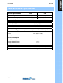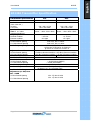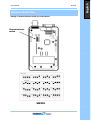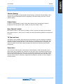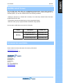
1
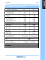
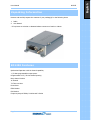
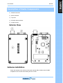
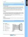
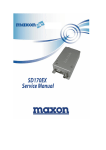
SD125E
Safety Information
WARNING
¾
NEVER connect the transceiver to an AC outlet. This may pose a fire hazard or result in an
electric shock.
¾
NEVER operate the radio transmitter without a suitable artificial load or antenna connected
¾ DO NOT allows children to operate transmitter-equipped radio equipment.
CAUTION
¾ DO NOT operates the transceiver near unshielded electrical blasting caps or in an explosive
atmosphere unless it is a type especially designed and qualified for such use.
¾ NEVER modify a transceiver or accessory except as instructed in the service manual,
engineering bulletins or formal communication as this may invalidate any warranty, guarantee
or type approval.
¾ NEVER use the transceiver in an aircraft.
¾ NEVER use the transceiver near to sensitive medical equipment or in areas where instructed
not to do so, e.g. Petrol filling stations.
¾
NEVER mount the transceiver unit on or near the Airbag or Airbag activation device.
¾
NEVER use an accessory not recommended or supplied by Maxon may cause damage to
equipment or injury to personnel, and will invalidate warranty.
¾
DO NOT use or place the transceiver in areas with temperatures below -30°C or above
+60°C, In areas subject to direct sunlight, such as the dashboard.
¾
AVOID placing the transceiver in excessively dusty environments.
¾
DO NOT fit the transceiver in such a manner that the antenna is next to, or touching,
exposed parts of the body, especially the face or eyes, while transmitting.
¾
ALWAYS Install the SD125E using a suitable heat sinking surface.
¾
NEVER operate the radio transmitter without a suitable artificial load or antenna connected.
¾
ALWAYS Secure locking nuts on DB09 connector and always disconnect power supply before
removing D-type connector.
For service or repair always return your radio to an authorised Maxon Dealer or warranty
conditions will be invalid.
Page 2
English
User Manual
SD125E
Table of Contents
Safety Information ................................................................................................................2
Table of Contents .................................................................................................................3
About your SD125E Series data radio......................................................................................4
About Your SD125E Radio .............................................................................................4
General SD125E Specification.................................................................................................5
SD125E Transmitter Specification ...........................................................................................6
SD125E Receiver Specification ...............................................................................................7
Unpacking Information ..........................................................................................................8
SD125E Features ..................................................................................................................8
Description of Radio Components ...........................................................................................9
SD125E Series Operation ..................................................................................................... 10
Pin-outs DB-09 Connector .................................................................................................... 10
Channel Selection ............................................................................................................... 11
Features............................................................................................................................. 12
Serial Command ................................................................................................................. 13
Audible alert tones .............................................................................................................. 14
Accessories available ........................................................................................................... 14
Page 3
English
User Manual
SD125E
About your SD125E Series data radio
About Your SD125E Radio
The MaxonCIC SD-125E Series of RF Link Modules from MaxonCIC utilizes the latest technology in
its design and manufacturing. Both the UHF and VHF models are PLL (Phase Lock Loop
Synthesizer) /microprocessor controlled, and offer one to five watts of power with 16 channel
capability. Multiple functions including 1200 to 2400 baud rates, AC and/or DC audio coupling,
FFSK and FSK modulation are standard in these fully programmable wide bandwidth RF Link
Module units.
The SD125E RF link module is a new and improved version of the popular SD125. With new
generation components, the module allows RF data communication between two distant points,
where a wire connection is not applicable. Some of the possible applications are remote parking
meters and barriers, data base transversal, remote control, sign and camera control and
telemetry.
The SD125E has a 9 pin D-type interface connector with 16 programmable channels selectable
via dip switch. The RF output power is 1 – 5 Watts giving superior range. The SD125E
programmer is Windows XP compatible and can be use with the older model SD125. With
compact size, cast Aluminum housing and multi voltage DC connection capability the SD125E
gives robustness and flexibility needed in remote and modern sites.
The radios are programmed using ACC 900E programming software, an Intel Pentium2 or higher
Personal Computer, Operating system is Microsoft windows 98, ME, 2000, and XP and Vista based
software, an interface module and a programming cable. This allows the radio to be tailored to
meet the requirements of the individual user and of the System(s) it is operating within.
To assure satisfaction from the radio, we urge you to thoroughly read the operation and function
information in this manual before operating your SD-125E U2/V2.
Applications of some of the functions described in this manual are determined by the system you
use. Your dealer will program your radio so that you have the greatest number of functions
possible relative to your needs.
Should you have questions regarding the operation of the radio, please consult your Dealer.
Antenna / RF connector
BNC type nominal 50Ω impedance
Programmer ACC 900E
Vista, XP, ME, 2000 and Windows based programmer
allowing personalisation of the SD-125E Series
Modems via the RS232 port.
Requires ACC-2125E Programming cable and
Universal programming CD ME430068.
Programming lead ACC–2125E
Squelch Calibration
Page 4
The squelch can be aligned using the ACC-900E
TAC-101D calibration lead will be required.
English
User Manual
SD125E
General SD125E Specification
General specification
Equipment Type
Model Series
Performance Specifications
Frequency Range
RF Output
Channel Spacing
Modulation Type
Intermediate Frequency
Number of Channels
Frequency Source
Operation Rating
External Power Supply
Temperature Range
VHF
UHF
Data radio (Wireless
Data radio (Wireless
Modem)
Modem)
SD-125E V2
SD-125E U2
TIA/EIA-603 /ETS 300-113
146-174MHz
440-470MHz
1-5W
1-5W
12.5KHz, 25KHz Programmable
F3D, F3E
45.1MHz & 455KHz
16
Synthesizer
Intermittent 90 : 5 : 5 (Standby : RX : TX)
(12 VDC Nominal) (Extreme 9.0V - 15.0 VDC )
Storage
From -40°C to +80°C
Operating
From -30°C to +60°C
Current Consumption
Standby(Muted)
< 65mA
Transmit 5Watts RF Power
< 2.0 A
Transmit 2Watts RF Power
Lock Time :
TX to RX attack time
RX to TX attack time
Dimensions
Weight
< 1.0 A
< 10ms
< 20ms (No Power Saving)
< 20ms
122mm (L) x 62mm (W) x 30mm (D)
242 grams
Page 5
English
User Manual
SD125E
SD125E Transmitter Specification
Transmitter specification
Model Series
Carrier Power
(Nom. Max. Min.)
Hi Power
Low Power
Sustained Transmission
Time 5 10 30Sec
(Nominal Conditions)
Frequency Error
Nominal condition
Extreme condition
Frequency Deviation
25 KHz Channel Spacing
12.5 KHz Channel Spacing
Audio Frequency Response
Adjacent Channel Power
25 KHz Channel Spacing
12.5 KHz Channel Spacing
Conducted Spurious Emission
Modulation Sensitivity
Hum & Noise :
25 KHz Channel Spacing
12.5 KHz Channel Spacing
Modulation Symmetry
Load Stability
Peak Deviation Range
Adjustment @ 1 KHz, Nom
Dev + 20dB
25 KHz Channel Spacing
12.5 KHz Channel Spacing
Page 6
VHF
UHF
SD-125E V2
SD-125E U2
5W < 6W > 4.5W
1W<1.5W>0.8W
5W < 6W > 4.5W
1W<1.5W>0.8W
Power : >90% >85% >80%
Power : >90% >85% >80%
< 0.5 KHz
±5.0 ppm
< 0.75 KHz
±3.0 ppm
Peak ±5.0, Min. ±3.8KHz
Peak ±2.5, Min. ±1.9KHz
Within +1/-3dB of 6dB octave
@ 300 Hz to 2.55 kHz for 12.5 kHz C.S.
@ 300 Hz to 3.0 kHz for 25 kHz C.S.
< 70 dBc @ Nominal Condition < 65 dBc @ Extreme Condition
< 60 dBc @ Nominal Condition < 55 dBc @ Extreme Condition
< -36 dBm
< -36 dBm
100mV RMS @ 60% Peak Dev.
> 40 dB (without PSOPH)
> 40 dB (with PSOPH)
< 10% Peak Dev @ 1KHz input for nominal dev. + 20dB
No osc at ≥ 10:1 VSWR all phase angles and suitable antenna
No destroy at ≥ 20:1 all phase angle
Min. 3.5, Max. 6.0KHz
Min. 1.5, Max. 4.0KHz
English
User Manual
SD125E
SD125E Receiver Specification
Receiver Specification
VHF
UHF
Model Series
SD-125E V2
SD-125E U2
< 0.28uV
< 0.30uV
< 0.28uV
< 0.30uV
< -113dBm
< -110dBm
> -3dB , < +3dB
< -113dBm
< -110dBm
> -3dB , < +3dB
Sensitivity (@ 12dB SINAD)
25 KHz Channel Spacing
12.5 KHz Channel Spacing
Sensitivity ( 1/100 Error Rate)
With ACC-513
With ACC-514
Amplitude Characteristic
Adjacent Channel Selectivity
25 KHz Channel Spacing(Nom.)
(Extreme Condition)
12.5 KHz Channel Spacing(Nom.)
(Extreme Condition)
Spurious Rejection(100KHz ~ 4GHz)
Image / Half IF Rejection
Intermodulation Response Rejection
±25 kHz/ 50 kHz
±50 kHz/ 100 kHz
Conducted Spurious Emission
9 KHz - 1 GHz
1 GHz – 4 GHz
RX Spurious Emissions (Radiated)
9 KHz - 1 GHz
1 GHz – 4 GHz
AF Distortion
Nominal condition
Extreme condition
RX Hum & Noise (only audio)
25 KHz Channel Spacing
12.5 KHz Channel Spacing
Receiver Response Time :
Squelch (factory pre-set)
Open
Close
Squelch Attack Time
RF Level at Threshold
RF Level at Threshold + 20dB
Squelch Decay Time
Antenna Socket Input Match
Temperature Stability for
L.O. Frequency
L.O. Frequency Aging Rate
Page 7
>
>
>
>
>
>
70
60
60
50
70
70
dB
dB
dB
dB
dB
dB
>
>
>
>
>
>
70
60
60
50
70
70
dB
dB
dB
dB
dB
dB
> 70 dB
> 70 dB
> 70 dB
> 70 dB
< -57 dBm
< -47 dBm
< -57 dBm
< -47 dBm
< -57 dBm
< -47 dBm
< -57 dBm
< -47 dBm
< 3%
< 10%
< 3%
< 10%
< 40 dB without PSOPH
< 40 dB with PSOPH
< 16 ms
< 40 dB without PSOPH
< 40 dB with PSOPH
< 16 ms
-113dBm
-116dBm
< 20 ms (RSSI), < 40 ms (Analog)
< 10 ms (RSSI), < 30 ms (Analog)
5 ms Min., 20ms Max.
> 10 dB Return Loss
1st < 5 ppm, 2nd < 15 ppm from -30° to + 60° C
±2 ppm/ year
English
User Manual
Unpacking Information
Remove and carefully inspect the contents of your package(s) for the following items:
1. Radio
2. User Manual
* If any items are missing or damaged please contact your Dealer or Maxon
SD125E Features
Synthesized Operation with 16 channel capability
1 / 5 Watt programmable output power
Programmable 12.5 / 25 KHz channel spacing
Busy channel lockout
16 channel
TX Time-out timer
Power Save
FFSK Modem
FSK Modem
Frequency steps 6.25KHz, 5.00KHz and 2.50KHz
Page 8
SD125E
English
User Manual
SD125E
Description of Radio Components
1) Antenna connector
2) DB-09 connector
3) Top cover
4) DIP-S/W channel selector
5) Jumper selector
Exterior View
Antenna installation
Fasten the antenna to the radio by turning the antenna cable clockwise onto the BNC
receptacle on left of radio when looking at front of radio.
Page 9
English
User Manual
SD125E
SD125E Series Operation
16 Channel select
Your radio’s channel can be selected by inner DIP-S/W or serial command inputted from external
control system. To change channel by inner DIP-S/W (4), you should open the upper cover and
then look for the DIP-S/W (4) on the digital board of the bottom cover. Once located change the
DIP-S/W to select wanted channel according to channel dip switch chart (See page 11).
To use a serial command for channel selection, it should be inputted by external equipment or
device (ex. Personal computer). See the message format for serial command for full details.
Transmit
The transmission will be made by various inputs such as PTT signal (Pin 3 of DB-15 connector),
TTL level is used as PTT signal and is active low. To maintain transmission, continuous PTT signal
input is required. When the channel is “clear”, input the PTT signal and transmit data. Remove
the PTT signal or input Rx serial command when you have finished transmission.
CAUTION: Operation of the transmitter without a proper antenna installed may result in
permanent damage to the radio.
Receive
When you have finished transmission, remove the PTT signal. You will be in the RX mode and can
receive data from another radio.
Pin-outs DB-09 Connector
DB9
CON 401
Pin1
Audio In (Data RX) 2
Pin2
Audio Out (Data TX) 5
Pin3
PTT 8
Pin4
GND (Ground) 11
Pin5
B+ (8-18 Volts DC) 14
Pin6
Carrier Detect (Squelch) 1
Pin7
N/C No Connect 4
Pin8
Switch 7
Pin9
N/C No Connect 10
Page 10
English
User Manual
SD125E
Channel Selection
Setting of channel selector switch for each channel
Channel selector
switch
SW401
Page 11
English
User Manual
SD125E
Features
Channel Spacing
The SD-125E is capable of programmable channel spacing, in both UHF and VHF bands. Each
channel can be programmed via the PC programmer, ACC-900E, having 12.5 KHz or 25 KHz
channel spacing.
Output Power
RF Power is programmable in the SD-125E. Each channel can be programmed via the PC
programmer to a high-power output, 5 Watts, or low-power output, 1 Watt.
Busy Channel Lockout
Busy Channel Lockout – ON: Upon PTT enable, if carrier is present, the radio will not transmit.
Busy Channel Lockout – OFF: Upon PTT enable, the radio will transmit regardless of the presence
of carrier.
TX Time-out timer
This feature, when enabled, limits the amount of time that the user can continuously transmit.
This time can be set in increments by 10 seconds from 10 seconds to 120 seconds. If the user
attempts to transmit longer than the TX Time-out period, five seconds prior to expiration, the
radio will release Time-out alert signal through pin 9 of the DB-15 connector and will cease
transmission.
Power Save
The Power Save function (PS) is used when an external battery is used as the power source.
When Power Save is enabled, the receiver PS on time can be set in 50 second increments up to
9950 seconds and PS OFF time can be set in 20 second increments up to 160 seconds. A delay
time can also be programmed in 1 second increments up to 8 seconds, this is the delay of PS
start time after a period of inactivity, programmed and allows the operator to set the length of
time the receiver.
Page 12
English
User Manual
SD125E
Serial Command
Serial RX/TX Data Format
(1)
(2)
(3)
(4)
(5)
Asynchronous Serial Data Transfer
Baud Rate : 4,800 bit/sec
Data Bit : 8bit , Non Parity
Stop Bit : 1bit
MSB first transmission
Each serial command consists of 3 bytes.
1st byte is command and 2nd is data required by command and 3rd is check sum to decide validity
of total contents.
Byte0
ST
1st Byte (Command)
SP
Byte1
ST
2nd Byte (Data)
SP
Byte2
ST
3rd Byte (Check Sum)
SP
Receive Command & data
Mode
Process
Complete
Commands
Transmit
Comman
d
(BYTE0)
0xaa
0x55
Transmit data
( BYTE1 )
Check sum( BYTE2 )
: Transmit Command
+ data
ACK
NACK
Note)
This command is return signal for receiving command.
If Byte2 and sum of Byte0 and Byte1 among received data are same, Radio would send
ACK data and execute command. If not, Radio sends Nack data.
User would go into next step if receives ACK data. If user receives Nack data, user
should send command again.
example) If user changes from 1st Channel to 2nd Channel,
User should send Channel Change Command (0x64,0x02,) ( 0x64 + 0x2 ) ) to Radio.
If Byte2 and sum of Byte0 and Byte1 among received data are same, Radio sends ACK
data to user and changes to 2nd channel. If not, Radio would send Nack data.
Page 13
English
User Manual
SD125E
Audible alert tones
Your SD-125E series data radio has a sophisticated microprocessor control which provides a
range of audible tone. if you connect the Speaker filtered OUT (Pin 9 of DB-15 connector) to an
external speaker, you can hear audible tones at the following conditions:
• Attempt to transmit on a channel that is already in use when busy channel lockout has been
programmed into the radio
• Transmission time has exceeded time-out timer programmed length
• When the other group or people finished transmission using repeater
See the status audible alert tones chart for full details.
Status
Warning
Description
Audible tone
Busy Channel lockout
Single Beep Tone
Before 5S T-O-T
Single Beep Tone
Transmit Hang on time
Single Beep Tone
Accessories available
Please contact the Maxon sales team for accessory information.
[email protected]
Tel: + 44 (0) 1442 267 777
Maxon House,
Cleveland Road,
Hemel Hempstead,
Hertfordshire,
United Kingdom,
HP2 7EY
Tel: + 44 (0) 1442 267 777
Fax: + 44 (0) 1442 215 515
www.maxoncic.co.uk
Page 14
English
User Manual
User Manual
SD125E
SD125E Series
This product is marked with
in accordance with the Class II product requirement specified in the R&TTE Directive 1999/5/EC.
This equipment is intended for use in:Austria, Belgium, Bulgaria, Cyprus, Czech Republic, Denmark, Estonia, Finland, France, Germany,
Greece, Hungary, Iceland, Ireland, Italy, Latvia, Liechtenstein, Lithuania, Luxembourg, Malta,
Netherlands, Norway, Poland, Portugal, Romania, Slovakia, Slovenia, Spain, Sweden, Switzerland
& United Kingdom
and requires authorisation (individual licence) for use.
We hereby declare that the above named product is in conformity to all the essential
requirements of Directive 1999/5/EC.
Con la presente si dichiara che il prodotto sopra menzionato è conforme ai requisiti essenziali
della Direttiva 1999/5/CE.
Declaramos que el producto mencionado más arriba cumple todos los requisitos esenciales de la
Directiva 1999/5/CE.
Wir möchten hiermit bekanntgeben, daß das oben genannte Produkt in Übereinstimmung mit
allen erforderlichen Bedürfnissen der 1999/5/EC Direktive seht
Nous déclarons que le produit référencé ci-dessus satisfait aux exigences
R&TTE 1999/5/EC qui lui sont applicables.
Nous déclarons que le produit référencé ci-dessus satisfait aux exigences
R&TTE 1999/5/EC qui lui sont applicables.
Page 15
User Manual
SD125E
Maxon House,
Cleveland Road,
Hemel Hempstead,
Hertfordshire,
United Kingdom,
HP2 7EY
Tel: + 44 (0) 1442 267 777
Fax: + 44 (0) 1442 215 515
[email protected]
www.maxoncic.co.uk
Page 1