1
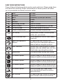
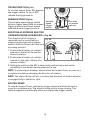
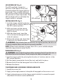
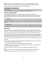
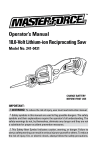
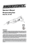
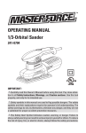
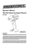
Operator’s Manual
12.0-Volt Lithium-Ion Impact Driver
241-0303
CHARGE BATTERY
BEFORE FIRST USE
IMPORTANT :
WARNING! To reduce the risk of injury, user must read instruction manual.
Safety symbols in this manual are used to flag possible dangers. The safety
symbols and their explanations require the operator’s full understanding. The
safety warnings do not, by themselves, eliminate any danger, and they are not
a substitute for proper accident prevention measures.
This Safety Alert Symbol indicates caution, warning, or danger. Failure to
obey a safety warning can result in serious injury to yourself or others. To reduce
the risk of injury, fire, or electric shock, always follow the safety precautions.
TABLE OF CONTENTS
Safety Symbols................................................................................................ Page 3
Safety Instructions......................................................................................... Page 5
Description....................................................................................................... Page 10
Assembly.......................................................................................................... Page 11
Operation.......................................................................................................... Page 12
Maintenance................................................................................................... Page 17
Troubleshooting............................................................................................... Page 18
Warranty........................................................................................................... Page 19
INTRODUCTION
SAVE THESE INSTRUCTIONS!
This cordless Impact Driver has many features for making its use more
pleasant and enjoyable. Safety, performance, and dependability have been
given top priority in the design of this product, making it easy to maintain and
operate.
2
SAFETY SYMBOLS
The purpose of safety symbols is to attract your attention to possible
dangers. The safety symbols and the explanations with them deserve
your careful attention and understanding. The symbol warnings do not, by
themselves, eliminate any danger. The instructions and warnings they give
are no substitutes for proper accident prevention measures.
WARNING! Be sure to read and understand all safety instructions in this
manual, including all safety alert symbols such as “DANGER,” ”WARNING,”
and “CAUTION” before using this Impact Driver. Failure to following all instructions listed below may result in electric shock, fire, and/or serious personal injury.
SYMBOL
SIGNAL
MEANING
Indicates an imminently hazardous situation,
DANGER! which, if not avoided, will result in death or
serious injury.
Indicates a potentially hazardous situation,
WARNING! which, if not avoided, could result in death or
serious injury.
Indicates a potentially hazardous situation,
CAUTION! which, if not avoided, could result in minor or
moderate injury.
(Without Safety Alert Symbol) Indicates a
NOTE:
situation that may result in property damage.
WARNING! To ensure safety and reliability, all repairs should be performed
by a qualified service technician.
WARNING! The operation of any power tool can
result in foreign objects being thrown into your eyes,
which can result in severe eye damage. Before
beginning power tool operation, always wear safety
goggles or safety glasses with side shields and a
full-face shield when needed. We recommend a
Wide Vision Safety Mask for use over eyeglasses or
standard safety glasses with side shields. Always
use eye protection which is marked to comply with
ANSI Z87.1
3
SAVE THESE INSTRUCTIONS
Some of these following symbols may be used on this tool. Please study them
and learn their meaning. Proper interpretation of these symbols will allow
you to operate the tool better and more safely.
V
A
Hz
W
min
.../min
Volts
Amperes
Hertz
Watt
Minutes
Alternating Current
Voltage
Current
Frequency (cycles per second)
Power
Time
Type of current
Direct Current
No Load Speed
Type or a characteristic of current
Rotational speed, at no load
Class II Construction
Double-insulated construction
Per Minute
Revolutions, strokes, surface speed,
orbits, etc., per minute
Do not expose to rain or use in damp
locations.
Wet Conditions Alert
Read The Operator’s
Manual
Eye Protection
Safety Alert
To reduce the risk of injury, user
must read and understand operator’s
manual before using this product.
Always wear safety goggles or safety
glasses with side shields and a full face
shield when operating this product.
Precautions that involve your safety.
No Hands Symbol
Failure to keep your hands away from the
blade will result in serious personal injury.
No Hands Symbol
Failure to keep your hands away from the
blade will result in serious personal injury.
No Hands Symbol
Failure to keep your hands away from the
blade will result in serious personal injury.
No Hands Symbol
Failure to keep your hands away
from the blade will result in serious
personal injury.
To reduce the risk of injury or damage,
avoid contact with any hot surface.
Hot Surface
4
SAFETY INSTRUCTIONS
GENRAL SAFETY RULES
WARNING: Read all safety warnings and instructions. Failure to follow
the warnings and instructions may result in electric shock, fire and / or serious injury.
Save all warnings and instructions for future reference.
The term power tool in the warnings refers to your mains-operated (corded)
power tool or battery-operated (cordless) power tool.
Work area safety
K
eep work area clean and well lit. Cluttered or dark areas invite
accidents.
D
o not operate power tools in explosive atmospheres, such as in the
presence of flammable liquids, gases or dust. Power tools create sparks
which may ignite the dust or fumes.
K
eep children and bystanders away while operating a power tool.
Distractions can cause you to lose control.
Electrical safety
P
ower tool plugs must match the outlet. Never modify the plug in any
way. Do not use any adapter plugs with earthed (grounded) power tools.
Unmodified plugs and matching outlets will reduce risk of electric shock.
A
void body contact with earthed or grounded surfaces such as pipes,
radiators, ranges and refrigerators. There is an increased risk of electric
shock if your body is earthed or grounded.
D
o not expose power tools to rain or wet conditions. Water entering a
power tool will increase the risk of electric shock.
D
o not abuse the cord. Never use the cord for carrying, pulling or
unplugging the power tool. Keep cord away from heat, oil, sharp edges
or moving parts. Damaged or entangled cords increase the risk of
electric shock.
W
hen operating a power tool outdoors, use an extension cord suitable
for outdoor use. Use of a cord suitable for outdoor use reduces the risk
of electric shock.
I f operating a power tool in a damp location is unavoidable, use a
residual current device (RCD) protected supply. Use of an RCD reduces
the risk of electric shock.
5
Personal safety
S
tay alert, watch what you are doing and use common sense when
operating a power tool. Do not use tool while tired or under the
influence of drugs, alcohol, or medication. A moment of inattention
while operating power tools may result in serious personal injury.
U
se personal protective equipment. Always wear eye protection.
Protective equipment such as dust mask, non-skid safety shoes, hard
hat, or hearing protection used for appropriate conditions will reduce
personal injuries.
P
revent unintentional starting. Ensure that the switch is in the OFF
position before connecting to power source and/or battery pack,
picking up or carrying the tool. Carrying power tools with your finger
on the switch or energising power tools that have the switch on invites
accidents.
R
emove any adjusting key or wrench before turning the power tool on.
A wrench or a key left attached to a rotating part of the power tool may
result in personal injury.
D
o not overreach. Keep proper footing and balance at all times. This
enables better control of the power tool in unexpected situations.
D
ress properly. Do not wear loose clothing or jewelry. Keep your hair,
clothing and gloves away from moving parts. Loose clothes, jewelry or
long hair can be caught in moving parts.
I f devices are provided for the connection of dust extraction and
collection facilities, ensure that these are connected and properly used.
Use of these devices can reduce dust-related hazards.
Power tool use and care
D
o not force the power tool. Use the correct power tool for your
application. The correct power tool will do the job better and more
safely at the rate for which it was designed.
D
o not use the power tool if the switch does not turn it on and off. Any
power tool that cannot be controlled with the switch is dangerous and
must be repaired.
D
isconnect the plug from the power source and/or the battery pack from
the power tool before making any adjustments, changing accessories,
or storing power tools. Such preventive safety measures reduce the risk
of starting the power tool accidentally.
S
tore idle power tools out of the reach of children and do not allow persons
unfamiliar with the power tool or these instructions to operate the power
tool. Power tools are dangerous in the hands of untrained users.
M
aintain power tools. Check for misalignment or binding of moving
parts, breakage of parts and any other condition that may affect the
power tool’s operation. If damaged, have the power tool repaired before
use. Many accidents are caused by poorly maintained power tools.
6
K
eep cutting tools sharp and clean. Properly maintained cutting tools
with sharp cutting edges are less likely to bind and are easier to control.
U
se the power tool, accessories, tool bits, etc. in accordance with
these instructions, taking into account the working conditions and the
work to be performed. Use of the power tool for operations different
from those intended could result in a hazardous situation.
Battery tool use and care
R
echarge only with the charger specified by the manufacturer. A
charger that is suitable for one type of battery pack may create a risk of
fire when used with another battery pack.
U
se power tools only with specifically designated battery packs. Use of
any other battery packs may create a risk of injury and fire.
W
hen battery pack is not in use, keep it away from other metal objects,
like paper clips, coins, keys, nails, screws or other small metal objects
that can make a connection from one terminal to another. Shorting the
battery terminals together may cause burns or a fire.
U
nder abusive conditions, liquid may be ejected from the battery;
avoid contact. If contact accidentally occurs, flush with water. If liquid
contacts eyes, additionally seek medical help. Liquid ejected from the
battery may cause irritation or burns.
Service
H
ave your power tool serviced by a qualified repair person using only
identical replacement parts.
SPECIFIC SAFETY RULES FOR CORDLESS IMPACT DRIVER
U
se only the battery pack and charger listed.
Battery pack
Charger
252-8016
252-8020
old power tools by insulated gripping surfaces when performing an
H
operation where the cutting tool may contact hidden wiring or its own
cord. Contact with a live wire will make exposed metal parts of the tool
live and shock the operator.
se protective gloves when removing the bit from the tool, or first allow
U
the bit to cool down. The bit may be hot after prolonged use.
se protective gloves when operating the tool. Protective gloves can help
U
to keep you from being burnt and hurt.
eep your hands away from the motor-housing vents. Hot gas comes from
K
the vents during operation.
7
o not operate the tool at full-load for more than 30 seconds, as this can
D
cause the motor to become too hot, which may damage the motor.
elease the trigger immediately when the screws are tightened to avoid
R
breaking the screw.
F or best results, your battery should be charged in a location where the
temperature is more that 50°F (10°C)but less that 104°F(40°C). Do not store
outside or in vehicles.
SAFETY RULES FOR CHARGER
WARNING! Read and understand all instructions. Failure to follow all instructions listed below may result in electric shock, fire, and/or serious personal injury.
efore using the battery charger, read all instructions and cautionary
B
markings in this manual and on the battery charger, the battery, and the
product using the battery to prevent misuse of the products and possible
injury or damage.
CAUTION! To reduce the risk of electric shock or damage to the charger
and battery, charge only those lithium-ion rechargeable batteries specifically
designated on your charger’s label. Other types of batteries may burst, causing personal injury or damage.
o not use the charger outdoors or expose it to wet or damp conditions.
D
Water entering the charger will increase the risk of electric shock.
se of an attachment not recommended or sold by the battery-charger
U
manufacturer may result in a risk of fire, electric shock or injury to
persons.
o not abuse the cord or charger. Never use the cord to carry the charger.
D
Do not pull the charger cord to disconnect the plug from receptacle.
Damage to the cord or charger could occur and create an electric shock
hazard. Replace damaged cords immediately.
ake sure that the cord is located so that it will not be stepped on,
M
tripped over, come in contact with sharp edges or moving parts, or
otherwise subjected to damage or stress. This will reduce the risk of
accidental falls, which could cause injury and damage to the cord, which
could then result in electric shock.
Keep the cord and charger from heat to prevent damage to the housing or
internal parts.
o not allow gasoline, oils, petroleum-based products, etc. to come in
D
contact with plastic parts. These materials contain chemicals that can
damage, weaken, or destroy plastic.
8
n extension cord should not be used unless absolutely necessary. Use
A
of an improper extension cord could result in a risk of fire and electric
shock. If an extension cord must be used, make sure that:
T he pins on plug of extension cord are the same number, size and shape
as those of the plug on charger.
T he cord is properly wired and in good electrical condition
T he size is large enough for AC ampere rating of charger as specified
below:
The Cord Length (Feet) 25’ 50’ 100’
Cord Size (AWG)
16 16 16
NOTE: AWG = American Wire Gauge
o not operate the charger with a damaged cord or plug, which could
D
cause shorting and electric shock. If damaged, have the charger repaired
or replaced by an authorized service technician.
o not operate the charger if it has received a sharp blow, been dropped,
D
or has otherwise been damaged in any way. Take it to an authorized
service technician for an electrical check to determine if the charger is in
good working order.
o not disassemble the charger. Take it to an authorized service
D
technician when service or repair is required. Incorrect reassembly may
result in a risk of electric shock or fire.
nplug the charger from the electrical outlet before attempting any
U
maintenance or cleaning to reduce the risk of electric shock.
isconnect charger from the power supply when not in use. This will
D
reduce the risk of electric shock or damage to the charger if metal items
should fall into the opening. It will also help prevent damage to the
charger during a power surge.
isk of electric shock. Do not touch the uninsulated portion of output
R
connector or uninsulated battery terminal.
ave these instructions. Refer to them frequently and use them to instruct
S
others who may use this tool. If you lend this tool to someone else, also
lend these instructions to them to prevent misuse of the product and
possible injury.
9
DESCRIPTION
KNOW YOUR IMPACT DRIVER (Fig.1)
Fig. 1 Chuck
Vents
Sleeve
LED Worklight
Direction-ofRotation Selector
(Forward/Center
Lock/ Reverse)
Variable-Speed
Trigger Switch
Battery pack
PRODUCT SPECIFICATIONS
Motor
12 Volt DC
Switch
VSR (Variable Speed Reversible)
No Load Speed
0-2200 RPM
Impacts per minute
0-2700 BPM
Torque
800 in.lbs
Driver Weight (with battery pack) 2lbs 2oz
Battery Type
Lithium-Ion
Battery Voltage
12 Volt DC
Charger Input
120-Volts, 60 Hz AC only
Optimum Charging Temperature 50°F (10° C) -104°F (40°C)
WARNING! The safe use of this product requires an understanding of the
information on the tool and in this operator’s manual, as well as knowledge of
the project you are attempting. Before use of this product, familiarize yourself
with all operating features and safety rules.
10
VARIABLE SPEED
The variable-speed trigger switch delivers higher speed with increased
pressure and lower speed with decreased trigger pressure.
FORWARD/CENTER LOCK/REVERSE
The direction-of-rotation selector located above the trigger switch changes
the direction of bit rotation. Setting the trigger switch in the OFF (center lock)
position helps to reduce the possibility of accidental starting.
LED WORK LIGHT
Pressing the trigger switch illuminates the LED worklight, located on the front
of the Impact Driver. This feature provides extra light for increased visibility.
ASSEMBLY
WARNING! If any part is broken or missing, do not attempt to plug in the
power cord, attach the battery or operate the Impact Driver until the broken or
missing part is replaced. Failure to do so could result in possible serious injury.
WARNING! Do not attempt to modify this Impact Driver or create accessories not recommended for use with this Impact Driver. Any such alteration
or modification is misuse and could result in a hazardous condition leading to
possible serious injury.
WARNING! To prevent accidental starting that could cause serious personal
injury, always remove the battery pack from the Impact Driver when assembling
parts.
UNPACKING
This product has been shipped completely assembled.
arefully remove the tool and any accessories from the box. Make sure
C
that all items listed in the packing list are included.
I nspect the tool carefully to make sure no breakage or damage occurred
during shipping.
o not discard the packing material until you have carefully inspected and
D
satisfactorily operated the tool.
PACKING LIST
Impact driver, 2pcs battery pack, 1pc charger, 1pc Philip bit, soft case and
Operator’s manual
11
OPERATION
BATTERY PROTECTION
The battery circuitry protects the battery pack from extreme temperature,
over discharge, and over-charge. To protect the battery from damage and
prolong its life, the battery pack circuitry will turn off the battery pack if it
becomes overloaded or if the temperature becomes too high during use. This
may happen in extremely high torque, binding, and stalling situations. The
battery pack will begin normal operation when it cools down.
NOTE: A significantly reduced run time after fully charging the battery pack
indicates that the battery is near the end of its usable life and must be replaced.
COLD WEATHER OPERATION
When the battery pack is very cold, it may “pulse” for the first minute of
use to warm itself. Put the battery pack on a tool and use the tool in a light
application. After about a minute, the battery pack will have warmed itself
and will operate normally.
WHEN TO CHARGE THE BATTERY PACK
It is not necessary to run down the battery pack charge before recharging.
The Lithium-Ion battery can be charged at any time and will not develop a
“memory” when charged after only a partial discharge.
Remove the battery pack from the tool when it is convenient for you and your
job. “Top off” the battery pack charge by charging it for a time before starting
a big job or long period of use.
Due to Lithium-Ion fade-free properties, the only time it is necessary to
charge the Lithium-Ion battery pack is when the pack has reached the end
of its charge. To signal the end of charge, power to the tool will drop quickly.
Charge the battery pack as needed.
HOW TO CHARGE THE BATTERY PACK
NOTE: This Lithium-Ion battery pack is shipped partially charged. Before
using it the first time, fully charge the battery pack.
A fully discharged battery pack will charge in about 30 minutes in a
surrounding temperature between 50° F (10° C) and 104° F (40° C).
1. C
harge the Lithium-Ion battery
pack with the correct charger.
Fig. 2
2. C
onnect the charger to a power
supply.
3. A
lign the raised ribs of the battery
pack with the slot in the charger.
4. I nsert the battery pack into the
charger (Fig. 2).
12
5. The charger will communicate with the battery pack to evaluate the
condition of the battery pack.
6. The green LED lights on the charger will flash while the battery pack
is charging. After charging is complete, the green LED will be on. The
flickering red light indicates a defective battery or a bad connection
between the battery and the charger.
7. The battery pack will fully charge if left on the charger, but it will not
overcharge.
LED FUNCTIONS OF CHARGER (Fig. 3)
LED INDICATOR
BATTERY
PACK
RED
LED
GREEN
LED
ACTION
Hot/Cold
battery
On
Off
Fast charge will begin when
battery returns to 50°F (10°C)
and 104°F (40°C).
Off
Battery pack or charger
is defective.
Defective Flashing
Charging
Off
Flashing
Charging
Fully
charged
Off
On
Charging is complete.
CHARGING A HOT BATTERY PACK
If the battery pack is above normal temperature range, the red LED will
illuminate and the green LED will be off. When the battery pack cools down
to approximately 104°F (40°C), the charger will automatically begin charging.
CHARGING A COLD BATTERY PACK
If the battery pack is below the normal temperature range, the red LED
will illuminate and the green LED will be off. When the battery warms to a
temperature of more than 50°F (10°C), the charger will automatically begin
charging.
DEFECTIVE BATTERY
If the charger detects a problem, the red LED will begin flashing and the
green LED will be off.
1. If registering as defective, remove and reinsert the battery pack in the
charger. If the LED status reads “defective” on second time, try charging a
different battery pack.
2. If a different battery pack charges normally, dispose of the defective
battery pack (see Maintenance section).
13
3. I f a different battery pack also indicates “defective,” the charger may be
defective.
BATTERY CHARGING
If the battery pack is being charged within a normal surrounding temperature
range (50 °F to 104°F), the green LED will begin flashing and the red LED will
be off. The battery pack will reach a full charge in 30 minutes.
BATTERY FULL
When the battery is fully charged, the green LED Light on the charger will
illuminate and the red LED light will be off.
De
tac
h
At
ta
1. L ock the trigger switch on the
Impact Driver by placing the
direction of rotation (forward/
center lock/reverse ) selector in
center (OFF) position.
2. A
lign the raised rib on the battery
pack with the grooves of the Driver,
and then attach the battery pack to
the Impact Driver.
ch
NOTE: The battery pack will fully charge, but will not overcharge, if left on the
charger.
NOTE: Charger may warm with several continuous charge cycles. This is part
of the normal operation of the charge. Charge in a well ventilated area.
Fig. 4
TO ATTACH BATTERY PACK (Fig. 4)
CAUTION! When placing the battery pack in the tool, be sure that the raised
rib on battery pack aligns with the groove inside the Impact Driver and that the
latches snap into place properly. Improper attachment of the battery pack can
cause damage to internal components.
TO DETACH BATTERY PACK (Fig. 4)
1. L ock the trigger switch on the Impact Driver by placing the direction of
rotation (forward/center lock/reverse ) selector in center position.
2. D
epress the battery release buttons located on the both sides of the
battery pack to release the battery pack.
3. P
ull the battery pack out and remove it from the tool.
WARNING! Battery tools are always in operating condition. Therefore, the
direction-of-rotation selector should always be locked when not in use or carrying at your side.
14
TRIGGER SWITCH (Fig. 5a)
Fig. 5a
To turn the impact driver ON, depress
the trigger switch. To turn it OFF,
release the trigger switch.
VARIABLE SPEED (Fig.5a)
The variable-speed trigger switch
delivers higher speed with increased
trigger pressure and lower speed
with decreased trigger pressure.
Variable
speed
trigger
switch
Direction
of rotation
selector
DIRECTION-OF-ROTATION SELECTOR
(FORWARD/CENTER LOCK/REVERSE ) (Fig. 5b)
The direction of bit rotation is
Fig. 5b
reversible and is controlled by a
selector located above the trigger
switch. With the Driver held in normal
operating position:
1. P
osition the direction-of-rotation
selector to the left of the tool for
REVERSE
FORWARD
forward rotation.
2. P
osition the direction-of-rotation
selector to the right of the tool for
reverse rotation.
3. S
etting the switch in the OFF (center lock) position helps reduce the
possibility of accidental starting when not in use.
NOTE: To prevent gear damage, always allow the Impact Driver to come to a
complete stop before changing the direction of rotation.
NOTE: The Impact Driver will not run unless the direction of rotation selector
is engaged fully to the left or right.
ELECTRIC BRAKE
To stop the Impact Driver, release the trigger switch and allow the tool to
come to a complete stop. The electric brake quickly stops rotating. This
feature engages automatically when you release the trigger switch.
15
LED WORKLIGHT (Fig. 6)
Fig. 6
The LED worklight, located on
the front of the Impact Driver, will
illuminate when the trigger switch is
depressed. This provides additional
light on the surface of the workpiece
for operation in lower-light areas. The
LED worklight will turn off when the
trigger switch is released.
LED worklight
INSTALLING BITS (Fig.7)
1. L ock the trigger switch by placing
the direction-of-rotation selector in Fig. 7
the OFF (center) position.
2. W
ith one hand, pull the sleeve
toward the front of the tool, and
hold it in place.
3. W
ith the other hand, insert the
1/4-in. bit into the hexagonal hole
in the bit retainer.
4. R
elease the sleeve and check that
it returns to its original position.
WARNING! If the sleeve does not return to its original position, the bit is not
correctly installed. Retry until the bit is properly installed.
NOTE: When the bit diameter is larger than 1/4 in., use a suitable adapter
(available separately) to install the bit.
REMOVING BITS (Fig.7)
WARNING! Use protective gloves when removing the bit from the tool, or
first allow the bit to cool down. The bit may be hot after prolonged use.
1.Lock the trigger switch by placing the direction-of rotation selector in the
OFF (center) position.
2.Pull the sleeve towards the front of the tool, and hold it in place.
3.Remove the bit from the hexagonal hole in the bit retainer.
4.Release the sleeve.
TIGHTENING AND LOOSENING SCREWS AND NUTS
1. Install the correct bit.
2. Apply just enough pressure to keep the bit engaged on the screw or nut.
3. Apply minimal pressure to the trigger switch initially. Increase the speed
only when full control can be maintained.
16
NOTE: This driver is equipped with an electric brake. When the brake is
functioning properly, sparks may be visible through the vent slots in the
housing. This is normal and is the action of the brake.
MAINTENANCE
WARNING! To avoid serious personal injury, always remove the battery pack
from the tool when cleaning or performing any maintenance.
GENERAL MAINTENANCE
Avoid using solvents when cleaning plastic parts. Most plastics are
susceptible to damage from various types of commercial solvents and may
be damaged by their use. Use clean cloths to remove dirt, dust, oil, grease,
etc.
WARNING! Do not at any time let brake fluids, gasoline, petroleum-based
products, penetrating oils, etc. to come in contact with plastic parts. Chemicals
can damage, weaken or destroy plastic which may result in serious personal
injury.
WARNING! When servicing, use only identical replacement parts. Use of
any other parts may create a hazard or cause product damage. To ensure safety
and reliability, all repairs should be performed by a qualified service technician.
BATTERIES:
The battery pack is equipped with Lithium-Ion rechargeable batteries. The
duration of use from each charge will depend on the type of work performed.
The batteries in this tool have been designed to provide maximum troublefree life. Like all batteries, they will eventually wear out. Do not disassemble
the battery pack or attempt to replace the batteries. Handling of the batteries,
especially when wearing rings and jewelry, could result in a serious burn.
To obtain the longest possible battery life, read and understand the operator’s
manual.
I t is good practice to unplug the Charger/Adapter and remove the LithiumIon battery pack when not in use.
For Lithium-Ion battery pack storage longer than 30 days:
tore the Lithium-Ion battery pack where the temperature is below 80°F
S
(26°C) and free of moisture.
Store Lithium-Ion battery packs in a 30%-50% charged condition.
Every six months of storage, fully charge the Lithium-Ion battery pack.
Exterior may be cleaned with a cloth or soft non-metallic brush.
17
BATTERY PACK REMOVAL AND PREPARATION FOR RECYCLING
To preserve natural resources, please recycle or dispose
of batteries properly. This product contains lithium-ion
batteries. Local, state, or federal laws may prohibit disposal
of lithium-ion batteries in ordinary trash. Consult your
local waste authority for information regarding available
recycling and/or disposal options.
WARNING! Upon removal of the battery pack for disposal or recycling, cover
the battery pack’s terminals with heavy-duty adhesive tape. Do not attempt to
destroy or disassemble battery pack or remove any of its components. LithiumIon batteries must be recycled or disposed of properly. Also, never touch both
terminals with metal objects and/or body parts as short circuit may result. Keep
away from children. Failure to comply with these warnings could result in fire
and/or serious injury.
TROUBLESHOOTING
PROBLEM
CAUSE
SOLUTION
The Driver does not
work
Battery is depleted
Charge the battery
Sleeve is not released
Release the sleeve
Bit cannot be
installed
Motor overheating
Bit does not fit the sleeve Use suitable adapter
Be sure cooling vents
are free from dust and
obstacles
18
Clean, clear vents. Do
not cover with hand
during operation
WARRANTY
3-MONTH MONEY BACK GUARANTEE:
This MASTERFORCE™ brand power tool carries our 3-Month Money Back
Guarantee. If you are not completely satisfied with your MASTERFORCE™
brand power tool for any reason within three (3) months from the date of
purchase, return the tool with your original receipt to any
retail
store, and we will provide you a refund – no questions asked.
3-YEAR LIMITED WARRANTY:
This MASTERFORCE™ brand power tool carries our famous No Hassle
3-Year Limited Warranty to the original purchaser. If the tool fails within
three (3) years from the date of purchase, simply bring this tool and its sale
receipt back to your nearest
retail store for a free equivalent
replacement within those three years. Notwithstanding the foregoing, this
limited warranty does not cover any damage that has resulted from abuse or
misuse of the Merchandise. This warranty: (1) excludes expendable parts
including but not limited to blades, belts, bits, light bulbs, and/or batteries;
(2) shall be void if this tool is used for commercial and/or rental purposes;
and (3) does not cover any losses, injuries to persons/property or costs. This
warranty does give you specific legal rights and you may have other rights,
which vary from state to state. Be careful, tools are dangerous if improperly
used or maintained. Seller’s employees are not qualified to advise you on
the use of this Merchandise. Any oral representation(s) made will not be
binding on seller or its employees. The rights under this limited warranty
are to the original purchaser of the Merchandise and may not be transferred
to any subsequent owner. This limited warranty is in lieu of all warranties,
expressed or implied including warranties or merchantability and fitness for
a particular purpose. Seller shall not be liable for any special, incidental, or
consequential damages. The sole exclusive remedy against the seller will be
for the replacement of any defects as provided herein, as long as the seller
is willing or able to replace this product or is willing to refund the purchase
price as provided above. For insurance purposes, seller is not allowed to
demonstrate any of these power tools for you.
For questions / comments, technical assistance or repair parts –
Please Call Toll Free at: 1-866-917-4374 (M-F 8am – 6pm)
SAVE YOUR RECEIPTS. THIS WARRANTY IS VOID WITHOUT THEM.
19
20