1
SC-27_25.book Page 1 Monday, April 6, 2009 7:15 PM
Operating Instructions
audio/video multi-channel receiver
SC-27_25.book Page 2 Monday, April 6, 2009 7:15 PM
FEDERAL COMMUNICATIONS COMMISSION DECLARATION OF CONFORMITY
This device complies with part 15 of the FCC Rules. Operation is subject to the following two conditions: (1) This
device may not cause harmful interference, and (2) this device must accept any interference received, including
interference that may cause undesired operation.
Product Name:
AUDIO/VIDEO MULTI-CHANNEL RECEIVER
Model Number:
SC-27 / SC-25
Responsible Party Name:
PIONEER ELECTRONICS SERVICE, INC.
Address:
1925 E. DOMINGUEZ ST. LONG BEACH, CA 90801-1760, U.S.A.
Phone:
1-800-421-1404
IMPORTANT NOTICE
THE SERIAL NUMBER FOR THIS EQUIPMENT IS LOCATED IN THE REAR.
PLEASE WRITE THIS SERIAL NUMBER ON YOUR ENCLOSED WARRANTY CARD AND KEEP IN A SECURE AREA.
THIS IS FOR YOUR SECURITY.
D1-4-2-6-1*_A1_En
NOTE:
This equipment has been tested and found to comply with the limits for a Class B digital device, pursuant to Part 15
of the FCC Rules. These limits are designed to provide reasonable protection against harmful interference in a
residential installation. This equipment generates, uses, and can radiate radio frequency energy and, if not installed
and used in accordance with the instructions, may cause harmful interference to radio communications. However,
there is no guarantee that interference will not occur in a particular installation. If this equipment does cause
harmful interference to radio or television reception, which can be determined by turning the equipment off and on,
the user is encouraged to try to correct the interference by one or more of the following measures:
— Reorient or relocate the receiving antenna.
— Increase the separation between the equipment and receiver.
— Connect the equipment into an outlet on a circuit different from that to which the receiver is connected.
— Consult the dealer or an experienced radio/TV technician for help.
D8-10-1-2_A1_En
CAUTION
This product satisfies FCC regulations when shielded
cables and connectors are used to connect the unit
to other equipment. To prevent electromagnetic
interference with electric appliances such as radios
and televisions, use shielded cables and connectors
for connections.
D8-10-3a_A1_En
This Class B digital apparatus complies with
Canadian ICES-003.
D8-10-1-3_A1_En
Information to User
Alterations or modifications carried out without
appropriate authorization may invalidate the user’s
right to operate the equipment.
D8-10-2_A1_En
CAUTION
The STANDBY/ON switch on this unit will not
completely shut off all power from the AC outlet.
Since the power cord serves as the main disconnect
device for the unit, you will need to unplug it from
the AC outlet to shut down all power. Therefore,
make sure the unit has been installed so that the
power cord can be easily unplugged from the AC
outlet in case of an accident. To avoid fire hazard,
the power cord should also be unplugged from the
AC outlet when left unused for a long period of time
D3-4-2-2-2a_A_En
(for example, when on vacation).
Operating Environment
Operating environment temperature and humidity:
+5 °C to +35 °C (+41 °F to +95 °F); less than 85 %RH
(cooling vents not blocked)
Do not install this unit in a poorly ventilated area, or in
locations exposed to high humidity or direct sunlight (or
strong artificial light)
D3-4-2-1-7c*_A1_En
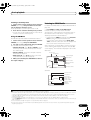
VENTILATION CAUTION
When installing this unit, make sure to leave space
around the unit for ventilation to improve heat
radiation (at least 20 cm at top, 10 cm at rear, and
20 cm at each side).
WARNING
Slots and openings in the cabinet are provided for
ventilation to ensure reliable operation of the
product, and to protect it from overheating. To
prevent fire hazard, the openings should never be
blocked or covered with items (such as newspapers,
table-cloths, curtains) or by operating the
D3-4-2-1-7b_A_En
equipment on thick carpet or a bed.
SC-27_25.book Page 3 Monday, April 6, 2009 7:15 PM
IMPORTANT
CAUTION
RISK OF ELECTRIC SHOCK
DO NOT OPEN
The lightning flash with arrowhead symbol,
within an equilateral triangle, is intended to
alert the user to the presence of uninsulated
“dangerous voltage” within the product’s
enclosure that may be of sufficient
magnitude to constitute a risk of electric
shock to persons.
CAUTION:
TO PREVENT THE RISK OF ELECTRIC
SHOCK, DO NOT REMOVE COVER (OR
BACK). NO USER-SERVICEABLE PARTS
INSIDE. REFER SERVICING TO QUALIFIED
SERVICE PERSONNEL.
The exclamation point within an equilateral
triangle is intended to alert the user to the
presence of important operating and
maintenance (servicing) instructions in the
literature accompanying the appliance.
D3-4-2-1-1_A1_En
1)
2)
3)
4)
5)
6)
7)
Read these instructions.
Keep these instructions.
Heed all warnings.
Follow all instructions.
Do not use this apparatus near water.
Clean only with dry cloth.
Do not block any ventilation openings. Install in
accordance with the manufacturer’s
instructions.
8) Do not install near any heat sources such as
radiators, heat registers, stoves, or other
apparatus (including amplifiers) that produce
heat.
9) Do not defeat the safety purpose of the polarized
or grounding-type plug. A polarized plug has two
blades with one wider than the other. A
grounding type plug has two blades and a third
grounding prong. The wide blade or the third
prong are provided for your safety. If the provided
plug does not fit into your outlet, consult an
electrician for replacement of the obsolete outlet.
10) Protect the power cord from being walked on or
pinched particularly at plugs, convenience
receptacles, and the point where they exit from
the apparatus.
WARNING
This equipment is not waterproof. To prevent a fire
or shock hazard, do not place any container filled
with liquid near this equipment (such as a vase or
flower pot) or expose it to dripping, splashing, rain
D3-4-2-1-3_B_En
or moisture.
WARNING
Before plugging in for the first time, read the following
section carefully.
The voltage of the available power supply differs
according to country or region. Be sure that the
power supply voltage of the area where this unit
will be used meets the required voltage (e.g., 230 V
D3-4-2-1-4_A_En
or 120 V) written on the rear panel.
11) Only use attachments/accessories specified by
the manufacturer.
12) Use only with the cart, stand, tripod, bracket, or
table specified by the manufacturer, or sold with
the apparatus. When a cart is used, use caution
when moving the cart/apparatus combination to
avoid injury from tip-over.
13) Unplug this apparatus during lightning storms
or when unused for long periods of time.
14) Refer all servicing to qualified service personnel.
Servicing is required when the apparatus has
been damaged in any way, such as power-supply
cord or plug is damaged, liquid has been spilled
or objects have fallen into the apparatus, the
apparatus has been exposed to rain or moisture,
does not operate normally, or has been dropped.
P1-4-2-2_En
This product is for general household purposes. Any
failure due to use for other than household purposes
(such as long-term use for business purposes in a
restaurant or use in a car or ship) and which requires
repair will be charged for even during the warranty
K041_En
period.
CAUTION
To prevent fire hazard, the Class 2 Wiring Cable
should be used for connection with speaker, and
should be routed away from hazards to avoid
damage to the insulation of the cable.
WARNING
To prevent a fire hazard, do not place any naked
flame sources (such as a lighted candle) on the
D3-4-2-1-7a_A_En
equipment.
SC-27_25.book Page 4 Monday, April 6, 2009 7:15 PM
WARNING: Handling the cord on this product or
cords associated with accessories sold with the
product will expose you to chemicals listed on
proposition 65 known to the State of California and
other governmental entities to cause cancer and
birth defect or other reproductive harm.
Wash hands after handling
D36-P4_A_En
If the AC plug of this unit does not match the AC
outlet you want to use, the plug must be removed
and appropriate one fitted. Replacement and
mounting of an AC plug on the power supply cord of
this unit should be performed only by qualified
service personnel. If connected to an AC outlet, the
cut-off plug can cause severe electrical shock. Make
sure it is properly disposed of after removal.
The equipment should be disconnected by removing
the mains plug from the wall socket when left
unused for a long period of time (for example, when
on vacation).
D3-4-2-2-1a_A_En
SC-27_25.book Page 5 Monday, April 6, 2009 7:15 PM
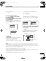
Thank you for buying this Pioneer product. Please read through these operating instructions so you will know how to operate
your model properly. After you have finished reading the instructions, put them away in a safe place for future reference.
Contents
Flow of settings on the receiver 8
01 Before you start
Our philosophy . . . . . . . . . . . . . . . . . . . . . . . . . . . . . . 9
Features. . . . . . . . . . . . . . . . . . . . . . . . . . . . . . . . . . . . 9
Checking what’s in the box . . . . . . . . . . . . . . . . . . . . 10
Installing the receiver . . . . . . . . . . . . . . . . . . . . . . . . 10
Loading the batteries . . . . . . . . . . . . . . . . . . . . . . . . . 11
Operating range of remote control unit . . . . . . . . . . . 11
Operating other Pioneer components with
this unit’s sensor . . . . . . . . . . . . . . . . . . . . . . . . . . . .
Switching components on and off using
the 12 volt trigger. . . . . . . . . . . . . . . . . . . . . . . . . . . .
Connecting a PC for Advanced MCACC output . . . . .
Connecting an HDMI-equipped component to
the front panel input . . . . . . . . . . . . . . . . . . . . . . . . .
Connecting an iPod . . . . . . . . . . . . . . . . . . . . . . . . . .
Connecting a USB device . . . . . . . . . . . . . . . . . . . . .
Plugging in the receiver. . . . . . . . . . . . . . . . . . . . . . .
40
41
41
42
43
43
44
02 Controls and displays
Remote control (In case of SC-27) . . . . . . . . . . . . . . .
Remote control (In case of SC-25) . . . . . . . . . . . . . . .
Front panel . . . . . . . . . . . . . . . . . . . . . . . . . . . . . . . .
Display. . . . . . . . . . . . . . . . . . . . . . . . . . . . . . . . . . . .
12
15
17
18
03 Connecting your equipment
Rear panel . . . . . . . . . . . . . . . . . . . . . . . . . . . . . . . . .
Determining the speakers’ application . . . . . . . . . . .
Other speaker connection . . . . . . . . . . . . . . . . . . . .
Placing the speakers . . . . . . . . . . . . . . . . . . . . . . . . .
THX speaker system setup . . . . . . . . . . . . . . . . . . .
Some tips for improving sound quality . . . . . . . . . .
Connecting the speakers . . . . . . . . . . . . . . . . . . . . . .
Installing your speaker system. . . . . . . . . . . . . . . . . .
Standard 5.1/6.1/7.1-channel surround
connections . . . . . . . . . . . . . . . . . . . . . . . . . . . . . .
Bi-amping your speakers. . . . . . . . . . . . . . . . . . . . .
Bi-wiring your speakers . . . . . . . . . . . . . . . . . . . . . .
Selecting the Surr Back system . . . . . . . . . . . . . . . . .
ZONE 2 setup . . . . . . . . . . . . . . . . . . . . . . . . . . . . .
Speaker B setup . . . . . . . . . . . . . . . . . . . . . . . . . . .
Bi-Amping setup . . . . . . . . . . . . . . . . . . . . . . . . . . .
About the audio connection. . . . . . . . . . . . . . . . . . . .
About the video converter . . . . . . . . . . . . . . . . . . . . .
Connecting your TV and playback components . . . . .
Connecting using HDMI . . . . . . . . . . . . . . . . . . . . .
Connecting your DVD player with
no HDMI output . . . . . . . . . . . . . . . . . . . . . . . . . . .
Connecting your TV with no HDMI input . . . . . . . . .
Connecting an HDD/DVD recorder, VCR and
other video sources . . . . . . . . . . . . . . . . . . . . . . . . . .
Connecting a satellite/cable receiver or
other set-top box . . . . . . . . . . . . . . . . . . . . . . . . . . . .
Connecting the multichannel analog inputs . . . . . . .
Connecting other audio components. . . . . . . . . . . . .
About the WMA9 Pro decoder. . . . . . . . . . . . . . . . .
Connecting additional amplifiers . . . . . . . . . . . . . . . .
Connecting AM/FM antennas . . . . . . . . . . . . . . . . . .
Connecting external antennas. . . . . . . . . . . . . . . . .
Connecting an XM Radio tuner . . . . . . . . . . . . . . . . .
Connecting a SiriusConnect™ tuner . . . . . . . . . . . . .
MULTI-ZONE setup . . . . . . . . . . . . . . . . . . . . . . . . . .
Making MULTI-ZONE connections. . . . . . . . . . . . . .
Connecting an IR receiver . . . . . . . . . . . . . . . . . . . . .
20
22
22
23
23
23
24
25
25
26
26
27
27
27
27
27
28
29
29
30
31
33
34
34
35
35
36
36
37
37
37
38
38
40
04 Basic Setup
Changing the OSD display language
(OSD Language) . . . . . . . . . . . . . . . . . . . . . . . . . . . .
Automatically setting up for surround sound
(Auto MCACC & Full Band Phase Control). . . . . . . . .
Problems when using the Auto MCACC Setup . . . .
The Input Setup menu . . . . . . . . . . . . . . . . . . . . . . . .
Input function default and possible settings . . . . . .
45
46
48
48
49
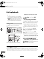
05 Basic playback
Playing a source . . . . . . . . . . . . . . . . . . . . . . . . . . . .
Playing a source with HDMI connection . . . . . . . . .
Selecting the multichannel analog inputs . . . . . . . .
Playing an iPod . . . . . . . . . . . . . . . . . . . . . . . . . . . . .
Playing back audio files stored on an iPod . . . . . . .
Playing a USB device. . . . . . . . . . . . . . . . . . . . . . . . .
Playing back audio files stored on a USB
memory device . . . . . . . . . . . . . . . . . . . . . . . . . . . .
Playing back photo files stored on a USB
memory device . . . . . . . . . . . . . . . . . . . . . . . . . . . .
About playable file formats . . . . . . . . . . . . . . . . . . .
Listening to the radio. . . . . . . . . . . . . . . . . . . . . . . . .
Improving FM sound . . . . . . . . . . . . . . . . . . . . . . . .
Using the noise cut mode . . . . . . . . . . . . . . . . . . . .
Using Neural THX . . . . . . . . . . . . . . . . . . . . . . . . . .
Tuning directly to a station . . . . . . . . . . . . . . . . . . .
Saving station presets . . . . . . . . . . . . . . . . . . . . . . .
Naming station presets . . . . . . . . . . . . . . . . . . . . . .
Listening to station presets . . . . . . . . . . . . . . . . . . .
Listening to Satellite Radio . . . . . . . . . . . . . . . . . . . .
Listening to XM Radio . . . . . . . . . . . . . . . . . . . . . . . .
Using XM HD Surround . . . . . . . . . . . . . . . . . . . . .
Saving channel presets . . . . . . . . . . . . . . . . . . . . . .
Using the XM Menu . . . . . . . . . . . . . . . . . . . . . . . .
Listening to SIRIUS Radio . . . . . . . . . . . . . . . . . . . . .
Saving channel presets . . . . . . . . . . . . . . . . . . . . . .
Using the SIRIUS Menu . . . . . . . . . . . . . . . . . . . . .
50
50
51
51
51
53
53
54
55
56
56
56
56
56
56
57
57
57
57
58
58
59
59
60
60
5
en
SC-27_25.book Page 6 Monday, April 6, 2009 7:15 PM
06 Listening to your system
08 KURO LINK
Auto playback. . . . . . . . . . . . . . . . . . . . . . . . . . . . . . . 61
Listening in surround sound. . . . . . . . . . . . . . . . . . . . 62
Standard surround sound . . . . . . . . . . . . . . . . . . . . 62
Using the Home THX modes . . . . . . . . . . . . . . . . . . 63
Using the Advanced surround effects . . . . . . . . . . . 63
Listening in stereo . . . . . . . . . . . . . . . . . . . . . . . . . . . 64
Using Front Stage Surround Advance . . . . . . . . . . . . 65
Using Stream Direct . . . . . . . . . . . . . . . . . . . . . . . . . . 65
Using surround back channel processing . . . . . . . . . 66
Using the Virtual Surround Back mode . . . . . . . . . . 66
Setting the Up Mix function . . . . . . . . . . . . . . . . . . . . 67
Selecting MCACC presets . . . . . . . . . . . . . . . . . . . . . 67
Choosing the input signal. . . . . . . . . . . . . . . . . . . . . . 68
Better sound using Phase Control and
Full Band Phase Control. . . . . . . . . . . . . . . . . . . . . . . 68
Using Phase Control . . . . . . . . . . . . . . . . . . . . . . . . 68
Using Full Band Phase Control . . . . . . . . . . . . . . . . 69
Making the KURO LINK connections . . . . . . . . . . . . . 84
Cautions on the KURO LINK function . . . . . . . . . . . 84
About connections with a product of a different
brand that supports the KURO LINK function . . . . . 85
KURO LINK Setup . . . . . . . . . . . . . . . . . . . . . . . . . . . 85
Setting the PQLS function . . . . . . . . . . . . . . . . . . . . . 86
Before using synchronization . . . . . . . . . . . . . . . . . . . 87
Synchronized amp mode . . . . . . . . . . . . . . . . . . . . . . 87
Synchronized amp mode operations . . . . . . . . . . . . 87
Canceling synchronized amp mode . . . . . . . . . . . . . 87
07 Playback with HOME MEDIA GALLERY
inputs
Enjoying the Home Media Gallery. . . . . . . . . . . . . . . . 71
Features of Home Media Gallery. . . . . . . . . . . . . . . . . 71
Steps to enjoy the Home Media Gallery . . . . . . . . . . . 71
Playing back audio files on the network and
listening to Internet radio stations . . . . . . . . . . . . . . 71
Connecting to the network through LAN interface . . . 72
Introduction . . . . . . . . . . . . . . . . . . . . . . . . . . . . . . . . 72
About network playback . . . . . . . . . . . . . . . . . . . . . . . 73
Windows Media Player. . . . . . . . . . . . . . . . . . . . . . . 73
Windows Media DRM . . . . . . . . . . . . . . . . . . . . . . . 73
DLNA . . . . . . . . . . . . . . . . . . . . . . . . . . . . . . . . . . . . 73
Content playable over a network. . . . . . . . . . . . . . . . 73
About playback behavior over a network . . . . . . . . . 73
Authorizing this receiver . . . . . . . . . . . . . . . . . . . . . 73
Playback with Home Media Gallery. . . . . . . . . . . . . . . 74
Playing back audio files stored on components on
the network . . . . . . . . . . . . . . . . . . . . . . . . . . . . . . . 75
Listening to Internet radio stations. . . . . . . . . . . . . . 75
Listening to Rhapsody . . . . . . . . . . . . . . . . . . . . . . . 77
Listening to Sirius Internet Radio . . . . . . . . . . . . . . . 77
Listening to Neural Music Direct . . . . . . . . . . . . . . . 77
Playing back your favorite songs . . . . . . . . . . . . . . . 77
About playable file formats. . . . . . . . . . . . . . . . . . . . 78
Advanced operations for Internet radio. . . . . . . . . . . . 79
Saving Internet radio stations. . . . . . . . . . . . . . . . . . 79
Retrieving saved Internet radio stations . . . . . . . . . . 79
Setting up the network . . . . . . . . . . . . . . . . . . . . . . . . 79
Checking the network settings . . . . . . . . . . . . . . . . . 81
Checking about the Accounts . . . . . . . . . . . . . . . . . 81
Software update . . . . . . . . . . . . . . . . . . . . . . . . . . . . 82
Glossary . . . . . . . . . . . . . . . . . . . . . . . . . . . . . . . . . . . 82
6
en
09 Using other functions
Setting the Audio options . . . . . . . . . . . . . . . . . . . . . . 88
About the SRC (Sampling Rate Converter)
(SC-27 only) . . . . . . . . . . . . . . . . . . . . . . . . . . . . . . . 89
Setting the Video options . . . . . . . . . . . . . . . . . . . . . . 90
Switching the speaker system . . . . . . . . . . . . . . . . . . 91
Using the MULTI-ZONE controls. . . . . . . . . . . . . . . . . 91
Making an audio or a video recording . . . . . . . . . . . . 92
Reducing the level of an analog signal . . . . . . . . . . . . 93
Using the sleep timer . . . . . . . . . . . . . . . . . . . . . . . . . 93
Dimming the display . . . . . . . . . . . . . . . . . . . . . . . . . 93
Switching the HDMI output . . . . . . . . . . . . . . . . . . . . 94
Checking your system settings . . . . . . . . . . . . . . . . . . 94
Resetting the system . . . . . . . . . . . . . . . . . . . . . . . . . 95
Default system settings . . . . . . . . . . . . . . . . . . . . . . 95
10 Controlling the rest of your system
(In case of SC-27)
Operating multiple receivers . . . . . . . . . . . . . . . . . . . 96
Setting the remote to control other components . . . . 96
Selecting preset codes directly. . . . . . . . . . . . . . . . . . 96
Programming signals from other remote controls . . . 97
Erasing one of the remote control button settings . . . 98
Resetting the remote control presets . . . . . . . . . . . . . 98
Confirming preset codes . . . . . . . . . . . . . . . . . . . . . . 98
Renaming input function names . . . . . . . . . . . . . . . . 98
Direct function . . . . . . . . . . . . . . . . . . . . . . . . . . . . . . 99
Multi Operation and System Off . . . . . . . . . . . . . . . . . 99
Programming a multi-operation or
a shutdown sequence . . . . . . . . . . . . . . . . . . . . . . . 99
Using multi operations. . . . . . . . . . . . . . . . . . . . . . 100
Using System off . . . . . . . . . . . . . . . . . . . . . . . . . . 100
Controls for TVs . . . . . . . . . . . . . . . . . . . . . . . . . . . . 101
10 Controlling the rest of your system
(In case of SC-25)
Operating multiple receivers . . . . . . . . . . . . . . . . . . 103
Setting the remote to control other components . . . 103
Selecting preset codes directly. . . . . . . . . . . . . . . . . 103
Programming signals from other remote controls . . . 104
Erasing the remote control button settings . . . . . . . 104
Multi Operation and System Off . . . . . . . . . . . . . . . . 105
Programming a multi-operation. . . . . . . . . . . . . . . 105
Using multi operations. . . . . . . . . . . . . . . . . . . . . . 105
Using System off . . . . . . . . . . . . . . . . . . . . . . . . . . 106
Resetting the remote control presets . . . . . . . . . . . . 106
Default preset codes . . . . . . . . . . . . . . . . . . . . . . . 106
Controls the components . . . . . . . . . . . . . . . . . . . . . 106
SC-27_25.book Page 7 Monday, April 6, 2009 7:15 PM
11 The Advanced MCACC menu
Making receiver settings from the Advanced
MCACC menu . . . . . . . . . . . . . . . . . . . . . . . . . . . . .
Automatic MCACC (Expert) . . . . . . . . . . . . . . . . . . .
Manual MCACC setup . . . . . . . . . . . . . . . . . . . . . . .
Fine Channel Level . . . . . . . . . . . . . . . . . . . . . . . .
Fine Speaker Distance. . . . . . . . . . . . . . . . . . . . . .
Standing Wave . . . . . . . . . . . . . . . . . . . . . . . . . . .
Acoustic Calibration EQ Adjust . . . . . . . . . . . . . . .
Acoustic Calibration EQ Professional . . . . . . . . . .
Precision Distance (SC-27 only). . . . . . . . . . . . . . .
Checking MCACC Data . . . . . . . . . . . . . . . . . . . . . .
Speaker Setting . . . . . . . . . . . . . . . . . . . . . . . . . . .
Channel Level . . . . . . . . . . . . . . . . . . . . . . . . . . . .
Speaker Distance . . . . . . . . . . . . . . . . . . . . . . . . .
Standing Wave . . . . . . . . . . . . . . . . . . . . . . . . . . .
Acoustic Cal EQ . . . . . . . . . . . . . . . . . . . . . . . . . .
Group Delay . . . . . . . . . . . . . . . . . . . . . . . . . . . . .
Output PC . . . . . . . . . . . . . . . . . . . . . . . . . . . . . . .
Data Management. . . . . . . . . . . . . . . . . . . . . . . . . .
Renaming MCACC presets . . . . . . . . . . . . . . . . . .
Copying MCACC preset data . . . . . . . . . . . . . . . . .
Clearing MCACC presets. . . . . . . . . . . . . . . . . . . .
13 Additional information
109
110
112
113
114
114
115
115
117
118
119
119
119
119
120
120
120
121
121
121
122
12 The system and the other setup
Making receiver settings from the System
Setup menu . . . . . . . . . . . . . . . . . . . . . . . . . . . . . . .
Manual speaker setup . . . . . . . . . . . . . . . . . . . . . . .
Surround back speaker setting . . . . . . . . . . . . . . .
Speaker Setting . . . . . . . . . . . . . . . . . . . . . . . . . . .
Channel Level . . . . . . . . . . . . . . . . . . . . . . . . . . . .
Speaker Distance . . . . . . . . . . . . . . . . . . . . . . . . .
X-Curve . . . . . . . . . . . . . . . . . . . . . . . . . . . . . . . . .
THX Audio Setting . . . . . . . . . . . . . . . . . . . . . . . . .
The Other Setup menu. . . . . . . . . . . . . . . . . . . . . . .
Multi Channel Input Setup . . . . . . . . . . . . . . . . . .
ZONE Audio Setup . . . . . . . . . . . . . . . . . . . . . . . .
Power ON Level Setup. . . . . . . . . . . . . . . . . . . . . .
Volume Limit Setup . . . . . . . . . . . . . . . . . . . . . . . .
Remote Control Mode Setup . . . . . . . . . . . . . . . . .
Flicker Reduction Setup . . . . . . . . . . . . . . . . . . . .
123
124
124
124
125
126
126
127
128
128
129
129
129
130
130
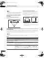
Speaker Setting Guide . . . . . . . . . . . . . . . . . . . . . . .
Positional relationship between speakers and
monitor . . . . . . . . . . . . . . . . . . . . . . . . . . . . . . . . .
Troubleshooting. . . . . . . . . . . . . . . . . . . . . . . . . . . .
Power . . . . . . . . . . . . . . . . . . . . . . . . . . . . . . . . . .
No sound . . . . . . . . . . . . . . . . . . . . . . . . . . . . . . .
Other audio problems . . . . . . . . . . . . . . . . . . . . . .
Video . . . . . . . . . . . . . . . . . . . . . . . . . . . . . . . . . . .
Settings. . . . . . . . . . . . . . . . . . . . . . . . . . . . . . . . .
Professional Calibration EQ graphical output . . . .
Display . . . . . . . . . . . . . . . . . . . . . . . . . . . . . . . . .
Remote control . . . . . . . . . . . . . . . . . . . . . . . . . . .
HDMI . . . . . . . . . . . . . . . . . . . . . . . . . . . . . . . . . .
Important information regarding the HDMI
connection . . . . . . . . . . . . . . . . . . . . . . . . . . . . . .
HOME MEDIA GALLERY . . . . . . . . . . . . . . . . . . . .
About status messages. . . . . . . . . . . . . . . . . . . . .
USB interface . . . . . . . . . . . . . . . . . . . . . . . . . . . .
XM radio messages. . . . . . . . . . . . . . . . . . . . . . . .
SIRIUS radio messages. . . . . . . . . . . . . . . . . . . . .
Surround sound formats . . . . . . . . . . . . . . . . . . . . .
Dolby. . . . . . . . . . . . . . . . . . . . . . . . . . . . . . . . . . .
DTS . . . . . . . . . . . . . . . . . . . . . . . . . . . . . . . . . . . .
Windows Media Audio 9 Professional . . . . . . . . . .
About iPod . . . . . . . . . . . . . . . . . . . . . . . . . . . . . . .
About THX . . . . . . . . . . . . . . . . . . . . . . . . . . . . . . . .
About Neural – THX Surround . . . . . . . . . . . . . . . . .
About SIRIUS and XM . . . . . . . . . . . . . . . . . . . . . . .
About FLAC . . . . . . . . . . . . . . . . . . . . . . . . . . . . . . .
FLAC Decoder . . . . . . . . . . . . . . . . . . . . . . . . . . . .
Auto Surround, ALC and Stream Direct with
different input signal formats . . . . . . . . . . . . . . . . .
Specifications . . . . . . . . . . . . . . . . . . . . . . . . . . . . .
Cleaning the unit . . . . . . . . . . . . . . . . . . . . . . . . . . .
Index . . . . . . . . . . . . . . . . . . . . . . . . . . . . . . . . . . . .
131
132
132
132
133
134
135
136
137
137
138
138
139
139
141
141
142
143
143
143
144
145
145
145
147
148
148
148
149
150
150
151
7
en
SC-27_25.book Page 8 Monday, April 6, 2009 7:15 PM
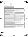
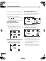
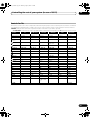
Flow of settings on the receiver
The unit is a full-fledged AV receiver equipped with an abundance of functions and terminals. It can be used easily
after following the procedure below to make the connections and settings.
The colors of the steps indicate the following:
Required setting item
Setting to be made as necessary
1
Before you start
• Checking what’s in the box (page 10)
• Loading the batteries (page 11)
9
The Input Setup menu (page 48)
(When using connections other than the
recommended connections)
2
•
•
•
•
Determining the speakers’ application (page
22)
7.1ch surround connection
5.1ch surround & Front Bi-amping connection
5.1ch surround & ZONE 2 connection
5.1ch surround & Speaker B connection
3
•
•
•
•
Connecting the speakers
Placing the speakers (page 23)
Connecting the speakers (page 24)
Standard 5.1/6.1/7.1-channel surround connections
(page 25)
Bi-amping your speakers (page 26)
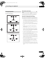
4
Connecting the components
• About the audio connection (page 27)
• About the video converter (page 28)
• Connecting your TV and playback components
(page 29)
• Connecting AM/FM antennas (page 36)
• Plugging in the receiver (page 44)
5
Power On
6
Changing the OSD display language (OSD
Language) (page 45)
7
Surround back speaker setting (page 124)
8
8
en
MCACC speaker settings
• Automatically setting up for surround sound (Auto
MCACC & Full Band Phase Control) (page 46)
10 Basic playback (page 50)
11 Switching the HDMI output (page 94)
12
•
•
•
•
•
•
•
•
•
Adjusting the sound and picture quality as desired
Using the various listening modes
Using surround back channel processing (page 66)
Better sound using Phase Control and Full Band
Phase Control (page 68)
Measure the all EQ type (SYMMETRY/ALL CH ADJ/
FRONT ALIGN) (page 110)
Change the channel level while listening (Tip on
page 126)
Switches on/off the Acoustic Calibration EQ, Sound
retriever or Dialog Enhancement (page 88)
Setting the PQLS function (page 86)
Setting the Audio options (Tone, Loudness or
Sound delay, etc.) (page 88)
Setting the Video options (page 90)
13
•
•
•
Other optional adjustments and settings
KURO LINK Setup (page 85)
The Advanced MCACC menu (page 109)
The system and the other setup (page 123)
14 Making maximum use of the remote control
• SC-27 – Operating multiple receivers (page 96)
• SC-27 – Setting the remote to control other
components (page 96)
• SC-25 – Operating multiple receivers (page 103)
• SC-25 – Setting the remote to control other
components (page 103)
SC-27_25.book Page 9 Monday, April 6, 2009 7:15 PM
Before you start
01
Chapter 1:
Before you start
Our philosophy
Pioneer is dedicated to making your home theater
listening experience as close as possible to the vision of
the moviemakers and mastering engineer when they
created the original soundtrack. We do this by focusing
on three important steps:
1
Achieving the highest possible sound quality
2 Allowing for customized acoustic calibration
according to any listening area
3 Fine-tuning the receiver with the help of worldclass studio engineers1
1 With the cooperation of AIR Studios, this receiver has
been designated AIR Studios Monitor:
Features
• Direct Energy HD Amplifier
Through a collaboration, Pioneer and ICEpower have
jointly development a unique class D amplifier called a
“Direct Energy High Fidelity Class D (HD) amplifier”. This
new generation reference amplifier offers outstanding
performance (high output of 770 W (SC-27)/700 W
(SC-25) simultaneous) with high sound quality and
reproduces the latest in multi-channel digital contents.
• Easy setup using Advanced MCACC
The Auto MCACC Setup provides a quick but accurate
surround sound setup, which includes the advanced
features of Professional Acoustic Calibration EQ. This
innovative technology measures the reverb
characteristics of your listening area, allowing you to
customize your system calibration with the help of a
graphical output that can be displayed on-screen or
using computer. With the additional benefits of
numerous MCACC preset memories, standing wave
control and microphone measurements from a series of
reference points, your home theater experience can be
truly customized for optimal surround sound.
• THX certified design (In case of SC-27)
This receiver bears the THX Ultra2 Plus logo, which
means it has passed a rigorous series of quality and
performance tests covering every aspect of the product.
This includes testing of pre-amplifier and power amplifier
performance and operation, and hundreds of other
parameters in both the digital and analog domain,
making your home theater experience as faithful as
possible to what the director intended.
• THX certified design (In case of SC-25)
This receiver bears the THX Select2 Plus logo, which
means it has passed a rigorous series of quality and
performance tests covering every aspect of the product.
This includes testing of pre-amplifier and power amplifier
performance and operation, and hundreds of other
parameters in both the digital and analog domain,
making your home theater experience as faithful as
possible to what the director intended.
• Dolby Digital and DTS decoding, including Dolby
Digital EX, Dolby Pro Logic IIx, DTS 96/24, DTS-ES, Dolby
Digital Plus, Dolby TrueHD, DTS-EXPRESS and DTS-HD
Master Audio
Dolby Digital and DTS decoding brings theater sound
right into your home with up to six channels of surround
sound, including a special LFE (Low Frequency Effects)
channel for deep, realistic sound effects.
The built-in Dolby Pro Logic IIx and DTS Neo:6 decoders
not only provide full surround sound decoding for Dolby
Surround sources, but will also generate convincing
surround sound for any stereo source.
Also, with the addition of a surround back speaker, you
can take advantage of the built-in Dolby Digital EX and
DTS-ES decoders for six-channel surround sound.
Furthermore, Dolby Digital Plus and Dolby TrueHD,
which are designed for the next-generation highdefinition media such as Blu-ray Disc and HD DVD,
support up to 7.1 channels and 8 channels respectively.
DTS-EXPRESS is a low-bitrate encoding technology
supporting up to 5.1 channels, with fixed data transfer
rates ranging from 24 kbps to 256 kbps (this encoding is
available only when signals are delivered to this receiver
as primary audio).
DTS-HD Master Audio delivers audio signals to listeners
without any loss of data with its high transfer rates.
• Phase Control
The Phase Control technology incorporated into this
receiver’s design provides coherent sound reproduction
through the use of phase matching for an optimal sound
image at your listening position.
• Full Band Phase Control
The Full Band Phase Control feature analyzes the
frequency-phase characteristics of the speakers
connected and corrects the phase distortion to the
flattened frequency-phase characteristics. This
9
en
SC-27_25.book Page 10 Monday, April 6, 2009 7:15 PM
01
Before you start
correction minimizes the group delay of the middle- and
low-frequency ranges against the high-frequency range
and improves the frequency-phase characteristics
across all ranges. Furthermore, the enhanced frequencyphase characteristics between channels ensure better
surround sound integration.
• Sound Retriever
The Sound Retriever feature employs DSP technology to
restore sound pressure and smooth jagged artifacts left
over after compression. This helps bring CD quality
sound back to WMA and MP3 audio files and achieves a
richer sense of presence when playing Dolby Digital, DTS
or WMA 9 Pro audio formats recorded in multiple
channels on DVDs and other discs.
• HOME MEDIA GALLERY
This receiver can play back contents stored on your
computer when your computer is connected to the LAN
terminal of this receiver. Also, you can listen to the
Internet radio stations.
• Front Stage Surround Advance
With the Front Stage Surround Advance feature, you can
enjoy seamless, natural surround sound effects using
only the front speakers, without deteriorating the quality
of the original sound.
• iPod/iPhone and USB Ready
This receiver has the terminals for connecting an iPod/
iPhone unit and a USB mass storage device.
The iPod terminal is ready for handling digital audio and
video, and this receiver’s enhanced compatibility makes
on-screen control of your iPod an added possibility.
The USB terminal allows you to listen to two-channel
audio from a USB mass storage device connected to this
receiver.
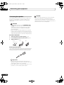
Checking what’s in the box
Please check that you’ve received the following supplied
accessories:
• Setup microphone (cable: 5 m (16.4 ft.))
• Optimum Surround
All movie creators do their best to express movie’s story
and use sounds 50 % to achieve it. They assume that the
finally mixed sounds should be best sound balance at
movie theaters that can perform a big sound. However, in
many cases, such a big sound is actually too much for
customer’s Home Theater environment, smaller volume
is normally used.
• AM loop antenna
• HDMI and digital video conversion
This receiver is compatible with the HDMI digital video
format, providing you with high-definition digital video/
audio via a single cable.
High-quality sound formats such as DTS-HD and Dolby
TrueHD are supported while this receiver is also
compatible with the Deep Color and x.v.Color feature
(x.v.Color is trademarks of Sony Corporation). You can
operate this receiver in synchronization with your Pioneer
component that supports the KURO LINK function by
connecting your component to this receiver via HDMI.
en
• XM and SIRIUS Ready
With the XM and SIRIUS Radio terminals, you’ll be up
and running in no time. This receiver’s enhanced
compatibility makes XM HD Surround playback as well
as on-screen control of your XM and SIRIUS Radio an
added possibility.
• Auto Level Control
When the source is played in Auto level control mode
(ALC), this receiver automatically equalizes the playback
sound level according to the variation in recording levels.
In such case, there is possibility that the sound balance
is changed/depressed compared to movie theaters. The
volume is smaller, the possibility is higher. In short,
smaller volume can NOT tell us stories properly as the
same as creator’s intention.
10
Also, the built-in digital video converter of this receiver
makes both de-interlacing and up-scaling possible, and
analog video signals being input are converted and
output as digital video signals at the HDMI terminal.
• Remote control unit
• Dry cell batteries x2
• FM wire antenna
• iPod cable
• Power cord
• Warranty card
• These operating instructions
Installing the receiver
• When installing this unit, make sure to put it on a
level and stable surface.
Don’t install it on the following places:
– on a color TV (the screen may distort)
– near a cassette deck (or close to a device that gives off
a magnetic field). This may interfere with the sound.
– in direct sunlight
– in damp or wet areas
– in extremely hot or cold areas
– in places where there is vibration or other movement
– in places that are very dusty
– in places that have hot fumes or oils (such as a kitchen)
• Do not touch this receiver’s bottom panel while the
power is turned on. The bottom panel gets hot when
the power is on, and touching it could cause burns.
SC-27_25.book Page 11 Monday, April 6, 2009 7:15 PM
Before you start
01
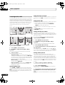
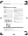
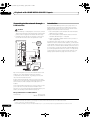
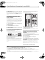
Loading the batteries
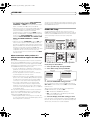
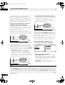
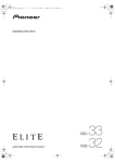
Operating range of remote control unit
In case of SC-27
The remote control may not work properly if:
• There are obstacles between the remote control and
the receiver’s remote sensor.
• Direct sunlight or fluorescent light is shining onto the
remote sensor.
In case of SC-25
CAUTION
Incorrect use of batteries may result in such hazards as
leakage and bursting. Observe the following precautions:
• Never use new and old batteries together.
• The receiver is located near a device that is emitting
infrared rays.
• The receiver is operated simultaneously with another
infrared remote control unit.
30°
30°
7 m (23 ft.)
• Insert the plus and minus sides of the batteries
properly according to the marks in the battery case.
• Batteries with the same shape may have different
voltages. Do not use different batteries together.
• When disposing of used batteries, please comply
with governmental regulations or environmental
public instruction’s rules that apply in your country or
area.
• WARNING
Do not use or store batteries in direct sunlight or
other excessively hot place, such as inside a car or
near a heater. This can cause batteries to leak,
overheat, explode or catch fire. It can also reduce the
life or performance of batteries.
11
en
SC-27_25.book Page 12 Monday, April 6, 2009 7:15 PM
02
Controls and displays
Chapter 2:
Controls and displays
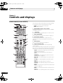
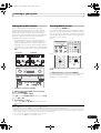
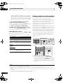
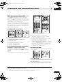
Remote control (In case of SC-27)
The remote has been conveniently color-coded according
to component control using the following system:
1
RECEIVER
2
3
MAIN
4
VIDEO1
12
3
MULTI
OPERATION
BD
DVD
TV
VIDEO2
DVR
CD
CD-R
TUNER
PHONO
MULTI CH
IN
XM
SIRIUS
INPUT SELECT
2 RECEIVER
This switches between standby and on for this receiver.
13
6
TV
SOURCE
CH
14
RECEIVER
VOL
8
9
AUDIO
PARAMETER
LIST
TOP MENU
BAND
5 INPUT SELECT
Use to select the input function (page 50).
MUTE
16
6 Character display (LCD)
This display shows information when transmitting
control signals.
PRESET
ENTER
10
PHASE CTRL
MPX
AUTO/ALC/
DIRECT
STEREO
PGM
MENU
SIGNAL SEL SLEEP
SBch
PQLS
CH LEVEL
PRESET – See Selecting preset codes directly on
page 96.
MEMORY
LEARNING – See Programming signals from other
remote controls on page 97.
STANDARD ADV SURR
DIMMER
AUDIO
MCACC
INFO
DISP
11
SETUP – Indicates the setup mode, from which you
choose the options below.
TUNE
THX
A.ATT
PRESET
RETURN
HOME
MENU
iPod CTRL
STATUS
The following commands are shown when you’re setting
the remote to control other components (see Controlling
the rest of your system (In case of SC-27) on page 96):
T.EDIT
GUIDE
CATEGORY
4 Input function buttons
Press to select control of other components (see
Controlling the rest of your system (In case of SC-27) on
page 96).
15
VIDEO
PARAMETER
TOOLS
TUNE
3 MULTI OPERATION
Use this button to perform multi operations (page 99).
VOL
7
TV CONTROL
INPUT
MUTE
• Blue – Other controls
1 MULTI-ZONE operation selector switch
Switch to perform operations in the main zone, ZONE 2
and ZONE 3 (page 91).
HOME MEDIA
HDMI GALLERY
USB
iPod
5
• White – Receiver control, TV Control
SOURCE
ZONE2
MULTI OP – See Multi Operation and System Off on
page 99.
17
SYS OFF – See Multi Operation and System Off on
page 99.
HDMI OUT
DIRECT F – See Direct function on page 99.
D.ACCESS
CLASS
ENTER
CLR
CH
RENAME – See Renaming input function names on
page 98.
ERASE – See Erasing one of the remote control button
settings on page 98.
RESET – See Resetting the remote control presets on
page 98.
READ ID – See Confirming preset codes on page 98.
12
en
SC-27_25.book Page 13 Monday, April 6, 2009 7:15 PM
Controls and displays
RC MODE – See Operating multiple receivers on
page 96.
7 TV CONTROL buttons
These buttons are dedicated to control the TV assigned to
the TV operation selector switch. Thus if you only have
one TV to hook up to this system assign it to the TV
operation selector switch (see page 96 or page 103 for
more on this).
02
Set the remote control operation selector switch to
RECEIVER first to access:
STATUS – Press to check selected receiver settings
(page 94).
PHASE CTRL – Press to switch on/off Phase Control
or Full Band Phase Control (page 68).
CH LEVEL – Press repeatedly to select a channel,
then use / to adjust the level (page 126).
– Use to turn on/off the power of the TV.
PQLS – Press to select PQLS setting (page 86).
VOL +/– – Use to adjust the volume on your TV.
CH +/– – Use to select channels.
AUTO/ALC/DIRECT – Switches between Auto
Surround (page 61), Auto level control, Optimum
Surround mode and Stream Direct mode (page 65).
MUTE – Use to mute the sound or cancel the mute
mode.
STEREO – Switches between stereo playback and
Front Stage Surround Advance modes (page 65).
INPUT – Use to select the TV input signal.
8 Tuner/component control buttons/HOME MENU
These button controls can be accessed after you have
selected the corresponding input function button (DVD,
DVR, TV, etc.). The BAND and T.EDIT tuner controls are
explained on page 56.
Set the remote control operation selector switch to
RECEIVER to access the following controls:
AUDIO PARAMETER – Use to access the Audio
options (page 88).
VIDEO PARAMETER – Use to access the Video
options (page 90).
HOME MENU – Use to access the Home Menu
(pages 45, 48, 85, 109, 118, 121, 123 and 128).
RETURN – Press to confirm and exit the current
menu screen (also use to return to the previous menu
with DVDs or to select closed captioning with DTV).
9 /// (TUNE/PRESET) /ENTER
Use the arrow buttons when setting up your surround
sound system (see page 109) and the Audio or Video
options (page 88 or 90). Also used to control DVD menus/
options and for deck 1 of a double cassette deck player.
Use TUNE / to find radio frequencies and use
PRESET / to find preset stations (page 56).
10 Component control buttons
The main buttons (, , etc.) are used to control a
component after you have selected it using the input
function buttons.
The controls above these buttons can be accessed after
you have selected the corresponding input function
button (for example DVD, DVR or TV). These buttons also
function as described below.
Press TUNER first to access:
MPX – Switches between stereo and mono reception
of FM broadcasts. If the signal is weak, then
switching to mono will improve the sound quality
(page 56). NOISE CUT MODE 1 to 2 can be selected
when receiving AM broadcasts.
STANDARD – Press for Standard decoding and to
switch between the various 2 Pro Logic IIx and
Neo:6 options (page 62).
ADV SURR – Use to switch between the various
surround modes (page 63).
THX – Press to select a Home THX listening mode
(page 63).
11 Number buttons and other receiver/component
controls
Use the number buttons to directly select a radio
frequency (page 56) or the tracks on a CD, DVD, etc.
ENTER can be used to enter commands for TV or DTV.
After set the remote control operation switch to
RECEIVER:
SIGNAL SEL – Use to select an input signal (page 68).
SLEEP – Use to put the receiver in sleep mode and
select the amount of time before sleep (page 93).
DIMMER – Dims or brightens the display (page 93).
A.ATT – Attenuates (lowers) the level of an analog
input signal to prevent distortion (page 93).
SBch – Use to select the surround/virtual back
channel mode (page 66).
MCACC – Press to switch between MCACC presets
(page 67).
HDMI OUT – Switch the HDMI output terminal
(page 94).
Press TUNER first to access:
D.ACCESS – After pressing, you can access a radio
station directly using the number buttons (page 56).
CLASS – Switches between the seven banks (classes)
of radio station presets (page 56).
12 SOURCE
Press to turn on/off other components connected to the
receiver (see page 96 for more on this).
13
en
SC-27_25.book Page 14 Monday, April 6, 2009 7:15 PM
02
Controls and displays
13 Remote control illumination button
Press to turn on/off the illumination of some of the
buttons and the LCD light.1
14 Remote control operation selector switch
Set to RECEIVER to operate the receiver, TV or SOURCE
to operate the TV or the source device.
When this switch is set to RECEIVER, the receiver can be
controlled (used to select the white commands above the
number buttons (A.ATT, etc.)). Also use this switch to set
up surround sound.
15 VOL +/–
Use to set the listening volume.
16 MUTE
Mutes the sound or restores the sound if it has been
muted (adjusting the volume also restores the sound).
17 AUDIO – Changes the audio or channel on DVD or
BD discs.
DISP – Switches between named station presets and
radio frequencies.
CH +/– – Use to select channels for DVD/DVR units.
Note
1 Press and hold in the remote control illumination button for 5 seconds to change the illumination mode 1 or 2. When set to LIGHT M2 (default),
the illumination only lights when the remote control illumination button is pressed. When switched to LIGHT M1, the illumination lights
whenever buttons are operated. Setting LIGHT M1 will shorten the service life of the batteries.
14
en
SC-27_25.book Page 15 Monday, April 6, 2009 7:15 PM
Controls and displays
02
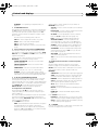
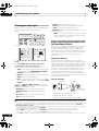
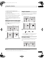
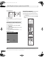
Remote control (In case of SC-25)
12
RECEIVER
SOURCE
1
13
DVD
TV
2
BD
DVR
CD
HOME MEDIA
CD-R GALLERY
iPod USB TUNER
SIRIUS
ENTER can be used to enter commands for TV or DTV.
INPUT
SELECT
HDMI OUT
1
2
3
SIGNAL SEL
MCACC
SLEEP
3
4
5
6
SBch
A.ATT
DIMMER
7
8
9
D.ACCESS
CH LEVEL
CLASS
0
ENTER
INPUT
MASTER
VOLUME
/CLR
14
TV CONTROL
4
3 Number buttons and other receiver/component
controls
Use the number buttons to directly select a radio
frequency (page 56) or the tracks on a CD, DVD, etc.
HDMI
XM
CH
VOL
MUTE
15
AUDIO
PARAMETER
5
6
VIDEO
PARAMETER
TUNE
LIST
TOOLS
TOP MENU
BAND
T.EDIT
GUIDE
ENTER
PRESET
PRESET
CATEGORY
RETURN
HOME
MENU
TUNE
iPod CTRL
AUTO/ALC/
MENU
DIRECT STEREO STANDARD ADV SURR
PGM
HDD
THX
DVD
PHASE CTRL
ANT
MPX
PQLS
AUDIO
INFO
MEMORY
CH
DISP
MULTI OPE TV CTRL RECEIVER
9
10
11
16
17
REMOTE
SETUP
ZONE 2
MAIN
Press RECEIVER first to access:
INPUT SELECT – Use to select the input function
(page 50).
HDMI OUT – Switch the HDMI output terminal
(page 94).
SIGNAL SEL – Use to select an input signal (page 68).
MCACC – Press to switch between MCACC presets
(page 67).
SLEEP – Use to put the receiver in sleep mode and
select the amount of time before sleep (page 93).
SBch – Use to select the surround back/virtual surround
back channel mode (page 66).
A.ATT – Attenuates (lowers) the level of an analog
input signal to prevent distortion (page 93).
DIMMER – Dims or brightens the display (page 93).
CH LEVEL – Press repeatedly to select a channel,
then use / to adjust the level (page 126).
Press TUNER first to access:
D.ACCESS – After pressing, you can access a radio
station directly using the number buttons (page 56).
CLASS – Switches between the seven banks (classes)
of radio station presets (page 56).
STATUS
7
8
2 Input function buttons
Press to select control of other components (see
Controlling the rest of your system (In case of SC-25) on
page 103).
ZONE 3
4 TV CONTROL buttons
These buttons are dedicated to control the TV assigned to
the TV operation selector switch. Thus if you only have
one TV to hook up to this system assign it to the TV
operation selector switch (see page 106 for more on this).
– Use to turn on/off the power of the TV.
RECEIVER
INPUT – Use to select the TV input signal.
CH +/– – Use to select channels.
The remote has been conveniently color-coded according
to component control using the following system:
• White – Receiver control, TV Control
• Blue – Other controls
1 RECEIVER
This switches between standby and on for this receiver.
VOL +/– – Use to adjust the volume on your TV.
5 Tuner/component control buttons/HOME MENU
These button controls can be accessed after you have
selected the corresponding input function button (DVD,
DVR, TV, etc.). The BAND and T.EDIT tuner controls are
explained on page 56 and page 57.
15
en
SC-27_25.book Page 16 Monday, April 6, 2009 7:15 PM
02
Controls and displays
Press RECEIVER first to access:
AUDIO PARAMETER – Use to access the Audio
options (page 88).
VIDEO PARAMETER – Use to access the Video
options (page 90).
HOME MENU – Use to access the Home Menu
(pages 45, 48, 85, 109, 118, 121, 123 and 128).
RETURN – Press to confirm and exit the current
menu screen (also use to return to the previous menu
with DVDs or to select closed captioning with DTV).
6 /// (TUNE/PRESET) /ENTER
Use the arrow buttons when setting up your surround
sound system (see page 109) and the Audio or Video
options (page 88 or 90). Also used to control DVD menus/
options and for deck 1 of a double cassette deck player.
Use TUNE/ to find radio frequencies and use PRESET
/ to find preset stations (page 56).
7 Component/Receiver control buttons
The main buttons (, , etc.) are used to control a
component after you have selected it using the input
function buttons.
The controls above these buttons can be accessed after
you have selected the corresponding input function
button (for example DVD, DVR or TV). These buttons also
function as described below.
Press TUNER first to access:
MPX – Switches between stereo and mono reception
of FM broadcasts. If the signal is weak, then switching
to mono will improve the sound quality (page 56).
NOISE CUT MODE 1 or 2 can be selected when this
unit is receiving AM broadcasts.
Press RECEIVER first to access:
AUTO/ALC/DIRECT – Switches between Auto
Surround (page 61), Auto level control, Optimum
Surround mode and Stream Direct mode (page 65).
STEREO – Switches between stereo playback and
Front Stage Surround Advance modes (page 65).
STANDARD – Press for Standard decoding and to
switch between the various 2 Pro Logic IIx and
Neo:6 options (page 62).
ADV SURR – Use to switch between the various
surround modes (page 63).
THX – Press to select a Home THX listening mode
(page 63).
PHASE CTRL – Press to switch on/off Phase Control
or Full Band Phase Control (page 68).
STATUS – Press to check selected receiver settings
(page 94).
PQLS – Press to select PQLS setting (page 86).
16
en
8
AUDIO – Changes the audio or channel on DVD or
BD discs.
DISP – Switches between named station presets and
radio frequencies.
CH +/– – Use to select channels for DVD/DVR units.
9 REMOTE SETUP
Use to input the preset code when making remote
control settings and to set the remote control mode
(page 103).
10 TV CTRL
Use this button to set preset code of your TV’s
manufacturer when controlling TV (see Selecting preset
codes directly on page 103 for more on this).
11 MULTI-ZONE operation selector switch
Switch to perform operations in the main zone, ZONE 2
and ZONE 3 (page 92).
12 Remote control LED
Lights when a command is sent from the remote control
(page 103).
13 SOURCE
Press to turn on/off other components connected to the
receiver (see page 103 for more on this).
14 MASTER VOLUME +/–
Use to set the listening volume.
15 MUTE
Mutes the sound or restores the sound if it has been
muted (adjusting the volume also restores the sound).
16 RECEIVER
Switches the remote to control the receiver (used to
select the white commands above the number buttons
(A.ATT, etc.)). Also use this button to set up surround
sound.
17
Press to turn on/off the illumination of some of the
buttons.
SC-27_25.book Page 17 Monday, April 6, 2009 7:15 PM
Controls and displays
02
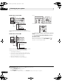
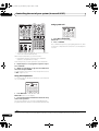
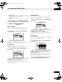
Front panel
1
2
3 4
5
6
INPUT
SELECTOR
MASTER
VOLUME
PHASE
CONTROL
ADVANCED
MCACC
PQLS
HDMI
STANDBY/ON
8
9 10 11
AUDIO
PARAMETER
(TUNE)
12
(PRESET)
ENTER
14
15
VIDEO
CONTROL
TUNER EDIT
7
13
(PRESET)
BAND AUTO SURR/ALC/ HOME
STREAM DIRECT THX
STANDARD ADVANCED
SURROUND SURROUND
STEREO
ON/OFF
MULTI-ZONE
SPEAKERS
iPod
iPhone
(TUNE)
HOME MENU
16
RETURN
17
HDMI 4
VIDEO CAMERA
18
1 STANDBY/ON
Switches the receiver between on and standby. Power
indicator lights when the receiver is on.
When the KURO LINK function is set to ON, the power
indicator lights when the power is in standby.
2 INPUT SELECTOR dial
Use to select an input function (page 50).
3
USB
MCACC
SETUP MIC
19
20
PHONES
21
5 Character display
See Display on page 18.
6
MASTER VOLUME dial
7 Front panel controls
To access the front panel controls, push gently on the
lower third portion of the panel with your finger.
PHASE CONTROL indicator – Lights to indicate
Phase Control or Full Band Phase Control is selected
(page 68).
ADVANCED MCACC indicator – Lights when EQ is
set to ON in the AUDIO PARAMETER menu
(page 88).
PQLS indicator – Lights when the PQLS feature is
active (page 86).
HDMI indicator – Blinks when connecting an HDMIequipped component; lights when the component is
connected (page 29).
4 Remote sensor
Receives the signals from the remote control (see
Operating range of remote control unit on page 11).
8 AUDIO PARAMETER
Use to access the Audio options (page 88).
9 VIDEO PARAMETER
Use to access the Video options (page 90).
17
en
SC-27_25.book Page 18 Monday, April 6, 2009 7:15 PM
Controls and displays
02
10 /// (TUNE/PRESET) /ENTER
Use the arrow buttons when setting up your HOME
MENU. Use TUNE / to find radio frequencies and use
PRESET / to find preset stations (page 56).
11 TUNER EDIT
Use with ////ENTER to memorize and name
stations for recall (page 56).
14 MULTI-ZONE controls
If you’ve made MULTI-ZONE connections (see MULTIZONE setup on page 38) use these controls to control the
sub zone from the main zone (see Using the MULTI-ZONE
controls on page 91).
15 SPEAKERS
Use to change the speaker system (page 91).
12 BAND
Switches between AM and FM radio bands (page 56).
16 HOME MENU
Press to access the Home Menu (pages 45, 48, 85, 109,
118, 121, 123 and 128).
13 Listening mode buttons
AUTO SURR/ALC/STREAM DIRECT – Switches
between Auto Surround (page 61), Auto level control,
Optimum Surround mode and Stream Direct mode
(page 65).
17 RETURN
Press to confirm and exit the current menu screen.
18 HDMI input connector
Use for connection to compatible HDMI device (Video
camera, etc.). See Connecting an HDMI-equipped
component to the front panel input on page 42.
HOME THX – Press to select a Home THX listening
mode (page 63).
STANDARD SURROUND – Press for Standard
decoding and to switch between the various 2 Pro
Logic IIx and Neo:6 options (page 62).
19 iPod/iPhone/USB terminals
Use to connect your Apple iPod as an audio and video
source, or connect a USB device for audio and photo
playback (page 43).
ADVANCED SURROUND – Use to switch between
the various surround modes (page 63).
20 MCACC SETUP MIC jack
Use to connect the supplied microphone (page 46).
STEREO – Switches between stereo playback and
Front Stage Surround Advance modes (page 65).
21 PHONES jack
Use to connect headphones. When the headphones are
connected, there is no sound output from the speakers.
Display
1
AUTO
PCM
HDMI
DIGITAL
ANALOG
2
L
SL
XL
18
19
45
6
CD-R
PHONO
iPod
20 21
2 Program format indicators
Light to indicate the channels being input when PCM
signals are being input. They do not indicate the audio
signals being output from the receiver.
L/R – Left front/Right front channel
C – Center channel
SL/SR – Left surround/Right surround channel
en
8 9 10 11 12 13 14
15
DSD PCM FULL BAND
TUNED
R 2DIGITAL PLUS
2TrueHD WMA9Pro MULTI-ZONE PQLS ALC ATT STEREO
SR DTS HD ES 96/24 S.RTRV SOUND UP MIX OVER MONO
XC XR
VIDEO HMG USB XM
DVD TV
TUNER SIRIUS
LFE MSTR CD
1 SIGNAL indicators
Light to indicate the currently selected input signal.
AUTO lights when the receiver is set to select the input
signal automatically (page 68).
18
7
16 17
C
AUTO SURROUND
STREAM DIRECT
2PROLOGIC x Neo:6
THX ADV.SURROUND
STEREO STANDARD
SP AB
SLEEP
8
3
BD
DVR
HDMI
[2]
[3]
dB
[4]
22
23
LFE – Low frequency effects channel (the (( )) indicators light
when an LFE signal is being input)
XL/XR – Two channels other than the ones above
XC – Either one channel other than the ones above, the mono
surround channel or matrix encode flag
3 Digital format indicators
Light when a signal encoded in the corresponding format
is detected.
4 S.RTRV
Lights when the Sound Retriever function is active
(page 88).
SC-27_25.book Page 19 Monday, April 6, 2009 7:15 PM
Controls and displays
02
5 MULTI-ZONE
Lights when the MULTI-ZONE feature is active (page 91).
16 Input function indicators
Light to indicate the input function you have selected.
6
DSD PCM – Light during DSD (Direct Stream Digital) to
PCM conversion with SACDs.
PCM – Lights during playback of PCM signals.
17 Scroll indicators
Light when there are more selectable items when making
the various settings.
7 FULL BAND
Lights when the Full Band Phase Control is switched on
(page 69).
18 Speaker indicators
Lights to indicate the current speaker system, A and/or B
(page 91).
8
19 SLEEP
Lights when the receiver is in sleep mode (page 93).
Listening mode indicators
AUTO SURROUND – Lights when the Auto Surround
feature is switched on (page 61).
ALC – Lights when the ALC (Auto level control) mode
is selected (page 65).
STREAM DIRECT – Lights when Direct/Pure Direct is
selected (page 65).
ADV.SURROUND – Lights when one of the
Advanced Surround modes has been selected
(page 63).
STEREO – Lights when stereo listening is switched
on (page 64).
STANDARD – Lights when one of the Standard
Surround modes is switched on (page 62).
THX – Lights when one of the Home THX modes is
selected (page 63).
20 Matrix decoding format indicators
2PRO LOGIC IIx – This lights to indicate 2 Pro
Logic II / 2 Pro Logic IIx decoding (page 62).
Neo:6 – When one of the Neo:6 modes of the receiver
is on, this lights to indicate Neo:6 processing (page 62).
21 MSTR
Lights during playback of DTS-HD Master Audio signal.
22 Character display
Displays various system information.
23 Remote control mode indicator
Lights to indicate the receiver’s remote control mode
setting. (Not displayed when set to 1.) (SC-27: page 96,
SC-25: page 103)
9
(PHASE CONTROL)
Lights when the Phase Control or Full Band Phase
Control is switched on (page 68).
10 Analog signal indicators
Light to indicate reducing the level of an analog signal
(page 93).
11 UP MIX
Lights when the Up Mix is switched on (page 67).
12 Tuner indicators
TUNED – Lights when a broadcast is being received.
STEREO – Lights when a stereo FM broadcast is being
received in auto stereo mode.
MONO – Lights when the mono mode is set using
MPX.
13 SOUND
Lights when any of the Midnight, Loudness or tone
controls feature is selected (page 88).
Lights when Dialog Enhancement is switched on.
14
Lights when the sound is muted (page 16).
15 Master volume level
Shows the overall volume level.
“---” indicates the minimum level, and “+12dB” indicates
the maximum level.
19
en
SC-27_25.book Page 20 Monday, April 6, 2009 7:15 PM
Connecting your equipment
03
Chapter 3:
Connecting your equipment
This receiver provides you with many connection possibilities, but it doesn’t have to be difficult. This page explains the
kinds of components you can connect to make up your home theater system.
Important
• Illustration shows the SC-27, however connections for the SC-25 are the same except where noted.
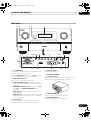
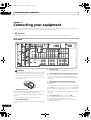
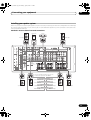
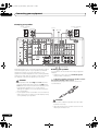
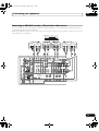
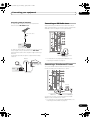
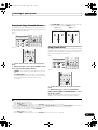
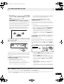
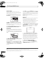
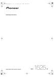
Rear panel
1 HDMI
3XM
IN
OUT
1
COAXIAL
(KURO
LINK )
ASSIGNABLE
IN 1 (DVD)
OUT
2
BD
IN
IN
1
4
IN 2 (CD)
7
IN 3
(VIDEO 2)
8IR
IN
IN 1
IN 2
(DVD)
2
12
13
PR
PB
PR
21
AC IN
ANTENNA
Y
(VIDEO 1)
14
15
PB
Y
ZONE 2 OUT
17
IN 3
(DVR)
ASSIGNABLE 1 - 3
PB
PR
Y
MONITOR OUT
SIGNAL
GND
FM UNBAL 75
COMPONENT VIDEO
16
AM LOOP
18
FRONT CENTER SURROUND SURROUND BACK
(Single)
L
S-VIDEO
PRE OUT
IN
1
IN 1
(TV/SAT)
IN
2
IN 2
(DVR)
R
VIDEO
ZONE 2
OUT
ZONE 3
OUT
PHONO
IN
CD
IN
DVD
IN
CD-R/TAPE
OUT
IN
TV/SAT
IN
VIDEO1
IN
DVR
VIDEO2
IN
OUT
IN
19
MULTI CH IN
FRONT CENTER SURROUND SURROUND BACK
L
L
OUT
9
R
R
IN
CONTROL
IN 4
(CD-R)
ASSIGNABLE
OUT
SUBWOOFER
SPEAKERS
20
R SURROUND BACK/
B
L (Single)
R
SURROUND
L
A
R
FRONT
L
CENTER
SPEAKER IMPEDANCE 6 Ω - 16 Ω .
ATTENTION:
ENCEINTE D'IMPEDANCE DE 6 Ω - 16 Ω .
SELECTABLE
SEE INSTRUCTION
MANUAL
OUT 2
Class 2 Wiring
CAUTION:
10
OUT 1
ASSIGNABLE
1-3
2LAN
11
VIDEO
3
(10/100)
1
SUBWOOFER
5
IN
IN
(OUTPUT
12V
TOTAL
50 mA
MAX)
SIRIUS
IN 3
(VIDEO1)
2
6
12 V
TRIGGER
SELECTABLE
VOIR LE MODE
D'EMPLOI
RS-232C
OPTICAL
CAUTION
• Before making or changing the connections, switch
off the power and disconnect the power cord from the
power outlet. Plugging in should be the final step.
• To avoid hum, do not lay connected cables over the
top of the receiver.
3
XM Radio input
See Connecting an XM Radio tuner on page 37.
4 Coaxial digital audio inputs (x3 (SC-27), x2 (SC-25))
Use for digital audio sources, including DVD players/
recorders, digital satellite receivers, CD players, etc.
See also The Input Setup menu on page 48 to assign
the inputs.
5 Optical digital audio inputs (x4)/outputs (x2)
Use the OUT jack for recording to a CD or MiniDisc
recorder.
See Connecting other audio components on page 35.
1 HDMI connectors (x6)
Multiple inputs and two outputs for high-quality audio/
video connection to compatible HDMI devices.
See Connecting your TV and playback components on
page 29.
See Switching the HDMI output on page 94.
2
LAN (10/100) terminal
See Playback with HOME MEDIA GALLERY inputs on
page 71.
20
en
Use the IN jacks for digital audio sources, including DVD
players/recorders, digital satellite receivers, CD players,
etc.
See also The Input Setup menu on page 48 to assign
the inputs.
6 12 V trigger jacks (total 50 mA max.) (x2)
Use to switch components in your system on and off
according to the input function of the receiver.
See Switching components on and off using the 12
volt trigger on page 41.
SC-27_25.book Page 21 Monday, April 6, 2009 7:15 PM
Connecting your equipment
7 SIRIUS Radio input
See Connecting a SiriusConnect™ tuner on page 37.
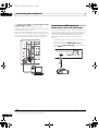
8 Remote inputs/output
Use for connection to an external remote control sensor
for use in a MULTI-ZONE setup, for example.
See Connecting an IR receiver on page 40.
9 Control input/output
Use to connect other Pioneer components so that you
can control all your equipment from a single IR remote
sensor.
See Operating other Pioneer components with this
unit’s sensor on page 40.
10 RS-232C connector
Use for connection to a PC for graphical output when
using Advanced MCACC or Full Band Phase Control.
See Connecting a PC for Advanced MCACC output on
page 41.
11 Component video inputs (x3)
Use the inputs to connect any video source that has
component video output, such as a DVD player.
See Connecting your DVD player with no HDMI output
on page 30.
03
18 Multichannel pre-amplifier outputs
Use to connect separate amplifiers for front, center,
surround, surround back and subwoofer channels.
See Connecting additional amplifiers on page 36 (see
also Installing your speaker system on page 25 for
powered subwoofer connection).
19 Multichannel analog audio inputs
7.1 channel inputs for connection to a DVD player with
multichannel analog outputs.
See Connecting the multichannel analog inputs on
page 34.
20 Speaker terminals
Use for connection to the main front, center, surround
and surround back speakers.
See Connecting the speakers on page 24.
21 AC power inlet
Connect the supplied power cord here.
See Plugging in the receiver on page 44.
12 SC-27 only: ZONE 2 component video output
Use to connect monitors or TVs in a separate room.
See MULTI-ZONE setup on page 38.
13 MULTI-ZONE audio/video outputs
Use to connect a second or third amplifier and monitors
or TVs in a separate room.
See MULTI-ZONE setup on page 38.
14 Composite, S-Video and Component video monitor
outputs
Use to connect monitors and TVs.
See Connecting your TV with no HDMI input on
page 31.
15 Stereo analog audio source inputs (x3)/output (x1)
Use for connection to audio sources such as CD players,
tape decks, turntables, etc.
See Connecting other audio components on page 35.
16 Audio/video source inputs (x5)/output (x1)
Use for connection to audio/visual sources, such as DVD
players/recorders, VCRs, etc. Each set of inputs has jacks
for composite video, S-Video and stereo analog audio.
See Connecting an HDD/DVD recorder, VCR and other
video sources on page 33.
17 AM and FM antenna terminals
Use to connect indoor or outdoor antennas for radio
broadcasts.
See Connecting AM/FM antennas on page 36.
21
en
SC-27_25.book Page 22 Monday, April 6, 2009 7:15 PM
03
Connecting your equipment
Determining the speakers’ application
Surround sound with a strong sense of presence can be
enjoyed by connecting 7 speakers and 1 subwoofer. It is
also possible to achieve high sound quality using bi-amp
connections and to enjoy music in other rooms using the
MULTI-ZONE feature. High sound quality can be
achieved with a minimum of two speakers.
• Be sure to connect speakers to the front left and right
channels ( L and R ).
• The Surr Back System setting must be made if you
use any of the connections shown below other than
[1] (see Selecting the Surr Back system on page 27).
[1] 7.1ch surround connection
(Simple connection & Best surround)
*Default setting
These connections prioritize surround sound with a
speaker layout like that in a movie theater.
• Surr Back System setting: Normal (default)
• If you have six speakers, either only connect one
surround back speaker (6.1 ch surround), or connect
for the 7.1-channel setting as shown on the diagram
below but without the center speaker.
[3] 5.1ch surround & ZONE 2 connection
(Multi Zone)
With these connections you can simultaneously enjoy
5.1-channel surround sound in the main zone with stereo
playback on another component in ZONE 2. (The
selection of input devices is limited.)
• Surr Back System setting: ZONE 2
L
L
R
SW
C
Front
right
Center
SR
Surround
left
Surround
right
SBL
SBR
Surround
back left
• Surr Back System setting: Front Bi-Amp
R
SW
C
Center
Front
right*
Subwoofer
Surround
left
SL
Surround
right
SR
*Bi-amp compatible speaker
22
en
L
R
Left
Right
ZONE 2
Surround
right
SR
SL
[4] 5.1ch surround & Speaker B connection
With these connections you can simultaneously enjoy
5.1-channel surround sound in the main zone with stereo
playback of the same sound on the B speakers.
• Surr Back System setting: Speaker B
R
SW
Front
left
C
Center
Speaker B
Front
right
Subwoofer
Surround
left
SL
Surround
right
SR
• Your favorite speaker connections can be selected
even if you have fewer than 5.1 speakers.
Bi-amping connection of the front speakers for high
sound quality with 5.1-channel surround sound.
L
Front
right
Other speaker connection
Surround
back right
[2] 5.1ch surround & Front Bi-amping connection
(High quality surround)
Front
left*
Center
Surround
left
Subwoofer
SL
C
Subwoofer
L
Front
left
R
SW
Front
left
• When not connecting a subwoofer, connect speakers
with low frequency reproduction capabilities to the
front channel. (The subwoofer’s low frequency
component is played from the front speakers, so the
speakers could be damaged.)
• After connecting, be sure to conduct the Auto
MCACC (speaker environment setting) procedure.
See Automatically setting up for surround sound
(Auto MCACC & Full Band Phase Control) on page 46.
SC-27_25.book Page 23 Monday, April 6, 2009 7:15 PM
Connecting your equipment
03
THX speaker system setup
Placing the speakers
To achieve the best possible surround sound, install your
speakers as shown below.
See also THX Audio Setting on page 127 to make the
settings that will give you the best sound experience
when using the Home THX modes (page 63).
5.1 channel surround system:
Center
Front right
Front left
Some tips for improving sound quality
Subwoofer
Where you put your speakers in the room has a big effect
on the quality of the sound. The following guidelines
should help you to get the best sound from your system.
120°
120°
Surround
right
Surround
left
6.1 channel surround system:
Center
Front left
Front right
Subwoofer
• The subwoofer can be placed on the floor. Ideally, the
other speakers should be at about ear-level when
you’re listening to them. Putting the speakers on the
floor (except the subwoofer), or mounting them very
high on a wall is not recommended.
• For the best stereo effect, place the front speakers 2
m to 3 m (6 ft. to 9 ft.) apart, at equal distance from
the TV.
• If you’re using a center speaker, place the front
speakers at a wider angle. If not, place them at a
narrower angle.
120°
120°
Surround
left
Surround
right
Surround Back
Center
Front right
Front left
Subwoofer
90°
90°
Surround
left
Surround
right
60°
• Place the center speaker above or below the TV so
that the sound of the center channel is localized at
the TV screen. Also, make sure the center speaker
does not cross the line formed by the leading edge of
the front left and right speakers.
• It is best to angle the speakers towards the listening
position. The angle depends on the size of the room.
Use less of an angle for bigger rooms.
7.1 channel surround system:
Surround back
left
If you are using a THX certified subwoofer use the THX
INPUT jack on the subwoofer (if your subwoofer has one)
or switch the filter position to THX on your subwoofer.
Surround back
right
• Surround and surround back speakers should be
positioned 60 cm to 90 cm (2 ft. to 3 ft.) higher than
your ears and tilted slight downward. Make sure the
speakers don’t face each other. For DVD-Audio, the
speakers should be more directly behind the listener
than for home theater playback.
• If the surround speakers cannot be set directly to the
side of the listening position with a 7.1-channel
system, the surround effect can be enhanced by
turning off the Up Mix function (see Setting the Up
Mix function on page 67).
• Try not to place the surround speakers farther away
from the listening position than the front and center
speakers. Doing so can weaken the surround sound
effect.
23
en
SC-27_25.book Page 24 Monday, April 6, 2009 7:15 PM
Connecting your equipment
03
CAUTION
Connecting the speakers
Each speaker connection on the receiver comprises a
positive (+) and negative (–) terminal. Make sure to
match these up with the terminals on the speakers
themselves.
CAUTION
• These speaker terminals carry HAZARDOUS LIVE
voltage. To prevent the risk of electric shock when
connecting or disconnecting the speaker cables,
disconnect the power cord before touching any
uninsulated parts.
• Make sure that all the bare speaker wire is twisted
together and inserted fully into the speaker terminal.
If any of the bare speaker wire touches the back panel
it may cause the power to cut off as a safety measure.
Bare wire connections
1
Twist exposed wire strands together. (fig. A)
2
Loosen terminal and insert exposed wire. (fig. B)
3
Tighten terminal. (fig. C)
fig. A
10 mm
fig. B
(3/8
fig. C
in.)
Banana plug connections
If you want to use speaker cables terminated with banana
plugs, screw the speaker terminal fully shut, then plug
the banana plug into the end of the speaker terminal.
Important
• Please refer to the manual that came with your
speakers for details on how to connect the other end
of the speaker cables to your speakers.
• Use an RCA cable to connect the subwoofer. It is not
possible to connect using speaker cables.
24
en
• Make sure that all speakers are securely installed.
This not only improves sound quality, but also
reduces the risk of damage or injury resulting from
speakers being knocked over or falling in the event of
external shocks such as earthquakes.
SC-27_25.book Page 25 Monday, April 6, 2009 7:15 PM
Connecting your equipment
03
Installing your speaker system
At the very least, front left and right speakers only are necessary. Note that your main surround speakers should always
be connected as a pair, but you can connect just one surround back speaker if you like (it must be connected to the
left surround back terminal).
Standard 5.1/6.1/7.1-channel surround connections
Center
Subwoofer
Front left
Front right
LINE LEVEL
INPUT
HDMI
XM
IN
OUT
1
COAXIAL
(KURO
LINK )
ASSIGNABLE
IN 1 (DVD)
OUT
2
12 V
TRIGGER
(OUTPUT
12V
TOTAL
50 mA
MAX)
IN 1
1
IN 2
(DVD)
PR
AC IN
PB
Y
ANTENNA
(VIDEO 1)
2
PR
ASSIGNABLE 1 - 3
PB
Y
ZONE 2 OUT
PB
PR
SIRIUS
IN 2 (CD)
IN 3
(DVR)
Y
MONITOR OUT
SIGNAL
GND
IN
FM UNBAL 75
COMPONENT VIDEO
AM LOOP
FRONT CENTER SURROUND SURROUND BACK
(Single)
L
S-VIDEO
PRE OUT
BD
IN
IN
1
IN 3
(VIDEO 2)
VIDEO
R
VIDEO
SUBWOOFER
IN 1
(TV/SAT)
IN 2
(DVR)
IN
1
IN
2
ZONE 2
OUT
ZONE 3
OUT
PHONO
IN
CD
IN
DVD
IN
CD-R/TAPE
OUT
IN
TV/SAT
IN
VIDEO1
IN
DVR
VIDEO2
IN
OUT
IN
MULTI CH IN
FRONT CENTER SURROUND SURROUND BACK
L
L
OUT
IN 3
(VIDEO1)
R
IN 4
(CD-R)
R
IN
CONTROL
IN
2
IR
OUT
SUBWOOFER
SPEAKERS
Class 2 Wiring
R SURROUND BACK/
B L (Single)
R
SURROUND
L
A R
FRONT
L
CENTER
CAUTION:
ASSIGNABLE
SPEAKER IMPEDANCE 6 Ω - 16 Ω .
ATTENTION:
IN
ENCEINTE D'IMPEDANCE DE 6 Ω - 16 Ω .
OUT 1
SELECTABLE
SEE INSTRUCTION
MANUAL
3
ASSIGNABLE
1-3
OUT 2
LAN
(10/100)
SELECTABLE
VOIR LE MODE
D'EMPLOI
RS-232C
OPTICAL
The surround back terminals can also be
used for the Speaker B and ZONE 2.
7.1 ch surround setting
Surround back left
Surround back right
Surround left
6.1 ch surround setting
Surround back
No connect
Speaker B setting
Speaker B - Right
Speaker B - Left
Surround right
ZONE 2 setting
ZONE 2 - Left
ZONE 2 - Right
25
en
SC-27_25.book Page 26 Monday, April 6, 2009 7:15 PM
03
Connecting your equipment
Bi-amping your speakers
Bi-amp compatible
speaker
Bi-amp compatible
speaker
Center
Subwoofer
High
High
Low
Low
Front right
Front left
HDMI
XM
IN
OUT
1
COAXIAL
(KURO
LINK )
ASSIGNABLE
IN 1 (DVD)
OUT
2
12 V
TRIGGER
(OUTPUT
12V
TOTAL
50 mA
MAX)
IN 1
1
IN 2
(DVD)
PR
AC IN
PB
ANTENNA
Y
(VIDEO 1)
2
PR
ASSIGNABLE 1 - 3
PB
Y
ZONE 2 OUT
PB
PR
SIRIUS
IN 2 (CD)
IN 3
(DVR)
Y
MONITOR OUT
SIGNAL
GND
IN
FM UNBAL 75
COMPONENT VIDEO
AM LOOP
FRONT CENTER SURROUND SURROUND BACK
(Single)
L
S-VIDEO
PRE OUT
BD
IN
IN
1
IN 3
(VIDEO 2)
VIDEO
R
VIDEO
SUBWOOFER
IN 1
(TV/SAT)
IN 2
(DVR)
IN
1
IN
2
ZONE 2
OUT
ZONE 3
OUT
PHONO
IN
CD
IN
DVD
IN
CD-R/TAPE
OUT
IN
TV/SAT
IN
VIDEO1
IN
VIDEO2
IN
DVR
OUT
IN
MULTI CH IN
FRONT CENTER SURROUND SURROUND BACK
L
L
OUT
IN 3
(VIDEO1)
R
IN 4
(CD-R)
R
IN
CONTROL
IN
2
IR
OUT
SUBWOOFER
SPEAKERS
Class 2 Wiring
R SURROUND BACK/
B L (Single)
R
SURROUND
A R
L
FRONT
L
CENTER
CAUTION:
ASSIGNABLE
SPEAKER IMPEDANCE 6 Ω - 16 Ω .
ATTENTION:
IN
ENCEINTE D'IMPEDANCE DE 6 Ω - 16 Ω .
OUT 1
SELECTABLE
SEE INSTRUCTION
MANUAL
3
ASSIGNABLE
1-3
OUT 2
LAN
(10/100)
SELECTABLE
VOIR LE MODE
D'EMPLOI
RS-232C
OPTICAL
Surround right
Bi-amping is when you connect the high frequency driver
and low frequency driver of your speakers to different
amplifiers for better crossover performance. Your
speakers must be bi-ampable to do this (having separate
terminals for high and low) and the sound improvement
will depend on the kind of speakers you’re using.
CAUTION
• Most speakers with both High and Low terminals
have two metal plates that connect the High to the
Low terminals. These must be removed when you are
bi-amping the speakers or you could severely
damage the amplifier. See your speaker manual for
more information.
Surround left
Bi-wiring your speakers
Your speakers can also be bi-wired if they support biamping.
• With these connections, the Surr Back System
setting makes no difference.
• To bi-wire a speaker, connect two speaker cords to
the speaker terminal on the receiver.
Using a banana plug for the second connection is
recommended.
• If your speakers have a removable crossover network,
make sure you do not remove it for bi-amping. Doing
so may damage your speakers.
CAUTION
• Don’t connect different speakers from the same
terminal in this way.
• When bi-wiring as well, heed the cautions for biamping shown at the left.
26
en
SC-27_25.book Page 27 Monday, April 6, 2009 7:15 PM
Connecting your equipment
03
Selecting the Surr Back system
About the audio connection
The surround back terminals can be used for bi-amping,
Speaker B and ZONE 2 connections, in addition to for the
surround back speakers. Make this setting according to
the application.
There are several types of audio input and output
terminals on this receiver. The receiver selects the first
available signal in the following order when you choose
AUTO as the input signal:
ZONE 2 setup
1 Connect a pair of speakers to the surround back
speaker terminals.
See Standard 5.1/6.1/7.1-channel surround connections
on page 25.
2 Select ‘ZONE 2’ from the Surr Back System menu.
See Surround back speaker setting on page 124 to do this.
Types of cables and
terminals
Sound signal priority
With these connections you can simultaneously enjoy
5.1-channel surround sound in the main zone with stereo
playback on another component in ZONE 2.
HDMI
Digital (Coaxial)
Transferable audio
signals
HD audio
Conventional digital audio
Digital (Optical)
Speaker B setup
You can listen to stereo playback in another room.
1 Connect a pair of speakers to the surround back
speaker terminals.
See Standard 5.1/6.1/7.1-channel surround connections
on page 25.
2 Select ‘Speaker B’ from the Surr Back System
menu.
See Surround back speaker setting on page 124 to do this.
RCA (Analog)
(White/Red)
Conventional analog audio
• With an HDMI cable, video and audio signals can be
transferred in high quality over a single cable.
Bi-Amping setup
Bi-amping connection of the front speakers for high
sound quality with 5.1-channel surround sound.
1 Connect Bi-amp compatible speakers to the front
and surround back speaker terminals.
See Bi-amping your speakers on page 26.
2 Select ‘Front Bi-Amp’ from the Surr Back System
menu.
See Surround back speaker setting on page 124 to do this.
CAUTION
• When connecting optical cables, be careful when
inserting the plug not to damage the shutter
protecting the optical socket.
• When storing optical cable, coil loosely. The cable
may be damaged if bent around sharp corners.
27
en
SC-27_25.book Page 28 Monday, April 6, 2009 7:15 PM
03
Connecting your equipment
About the video converter
The video converter ensures that all video sources are output through all of the MONITOR OUT jacks. The only
exception is HDMI: since this resolution cannot be downsampled, you must connect your monitor/TV to the receiver’s
HDMI video outputs when connecting this video source.1
If several video components are assigned to the same input function (see The Input Setup menu on page 48), the
converter gives priority to HDMI, component, S-Video, then composite (in that order).
INPUT
SELECTOR
MASTER
VOLUME
PHASE
CONTROL
ADVANCED
MCACC
PQLS
HDMI
STANDBY/ON
This receiver
Source device
High picture quality
Terminal for
connection with
source device
TV monitor
Terminal for
connection with TV
monitor
HDMI IN
PR
PB
Types of cables
HDMI OUT
Y
PR
PB
Y
COMPONENT
VIDEO IN
COMPONENT VIDEO
MONITOR OUT
S-VIDEO IN
S-VIDEO
MONITOR OUT
VIDEO IN
VIDEO
MONITOR OUT
Video signals can be output
• For optimal video performance, THX recommends
switching Digital Video Conversion (in Setting the
Video options on page 90) OFF.
This product incorporates copyright protection
technology that is protected by method claims of certain
U.S. patents and other intellectual property rights owned
by Macrovision Corporation and other rights owners.
Use of this copyright protection technology must be
authorized by Macrovision Corporation, and is intended
for home and other limited viewing uses only unless
otherwise authorized by Macrovision Corporation.
Reverse engineering or disassembly is prohibited.
Note
1 • If the video signal does not appear on your TV or flat panel TV, try adjusting the resolution settings on your component or display. Note that
some components (such as video game units) have resolutions that may not be converted. In this case, try switching Digital Video Conversion
(in Setting the Video options on page 90) OFF.
• The signal input resolutions that can be converted from the component video input for the HDMI output are 480i/576i, 480p/576p, 720p and
1080i. 1080p signal cannot be converted.
• Only signals with an input resolution of 480i/576i can be converted from the component video input for the composite and S-Video MONITOR
OUT.
28
en
SC-27_25.book Page 29 Monday, April 6, 2009 7:15 PM
Connecting your equipment
03
Connecting your TV and playback components
Connecting using HDMI
If you have an HDMI or DVI (with HDCP) equipped component (Blu-ray disc player, etc.), you can connect it to this
receiver using a commercially available HDMI cable.
If the TV and playback components support the Pioneer KURO LINK feature, the convenient KURO LINK functions can
be used (see KURO LINK on page 84).
Other HDMI/DVIequipped component
HDMI IN
HDMI OUT
HDMI/DVI-compatible monitor
or flat panel TV
HDMI/DVI-compatible
Blu-ray disc player
Select one
AUDIO OUT
DIGITAL OUT
OPTICAL
R ANALOG L
This connection is
required in order to
listen to the sound of
the TV over the receiver.
HDMI OUT
HDMI
XM
IN
OUT
1
COAXIAL
(KURO
LINK )
ASSIGNABLE
IN 1 (DVD)
OUT
2
IN 2 (CD)
BD
IN
IN
1
(OUTPUT
12V
TOTAL
50 mA
MAX)
IN 1
1
IN 2
(DVD)
IN 3
(VIDEO 2)
IN 1
(TV/SAT)
IN 2
(DVR)
PR
PR
Y
ANTEN
ASSIGNABLE 1 - 3
PB
Y
ZONE 2 OUT
PB
PR
Y
MONITOR OUT
SIGNAL
GND
COMPONENT VIDEO
S-VIDEO
VIDEO
IN
1
IN
2
PB
(VIDEO 1)
2
IN
IR
IN 3
(DVR)
SIRIUS
VIDEO
ZONE 2
OUT
ZONE 3
OUT
PHONO
IN
CD
IN
CD-R/TAPE
OUT
IN
DVD
IN
TV/SAT
IN
V
L
OUT
IN 3
(VIDEO1)
R
IN
CONTROL
IN
2
12 V
TRIGGER
IN 4
(CD-R)
OUT
SPEAKERS
Class 2 Wiring
R SURROUND BACK/
B L (Single)
R
CAUTION:
ASSIGNABLE
SPEAKER IMPEDANCE 6 Ω - 16 Ω .
ATTENTION:
IN
ENCEINTE D'IMPEDANCE DE 6 Ω - 16 Ω .
OUT 1
SELECTABLE
SEE INSTRUCTION
MANUAL
3
ASSIGNABLE
1-3
OUT 2
LAN
(10/100)
SELECTABLE
VOIR LE MODE
D'EMPLOI
RS-232C
OPTICAL
• When connecting a Blu-ray disc player, connect the
player to the receiver’s BD IN terminal.
• When connecting to an HDMI/DVI-compatible
monitor or a flat panel TV using the HDMI OUT 2
terminal, switch the HDMI output setting to HDMI
OUT 2 or HDMI OUT ALL. See Switching the HDMI
output on page 94.
• The HDMI indicator lights on the front panel when an
HDMI-equipped component is connected.
• If your Blu-ray disc player offers multi-channel analog
audio outputs, see Connecting the multichannel
analog inputs on page 34.
• The sound of the TV cannot be heard over the receiver
if the TV is connected using an HDMI cable.
If you want to listen to the sound of the TV over the
receiver, connect the receiver and TV with audio
cables.
• For input components, connections other than HDMI
connections are also possible (see Connecting your
DVD player with no HDMI output on page 30).
29
en
SC-27_25.book Page 30 Monday, April 6, 2009 7:15 PM
03
Connecting your equipment
Connecting your DVD player with no HDMI output
This diagram shows connections of a TV (with HDMI input) and DVD player (or other playback component with no
HDMI output) to the receiver.
DVD player, etc.
Select one
Select one
AUDIO OUT
DIGITAL OUT
COAXIAL OPTICAL
VIDEO OUT
S-VIDEO VIDEO
COMPONENT VIDEO OUT
R ANALOG L
PR
PB
Y
HDMI/DVI-compatible
monitor or flat panel TV
HDMI IN
HDMI
XM
IN
OUT
1
COAXIAL
(KURO
LINK )
ASSIGNABLE
IN 1 (DVD)
OUT
2
IN 2 (CD)
BD
IN
IN
1
12 V
TRIGGER
(OUTPUT
12V
TOTAL
50 mA
MAX)
IN 2
(DVD)
IR
2
PR
SIGNAL
GND
ZONE 3
OUT
PHONO
IN
CD-R/TAPE
OUT
IN
DVD
IN
L
SPEAKERS
Class 2 Wiring
CAUTION:
SPEAKER IMPEDANCE 6 Ω - 16 Ω .
ATTENTION:
ENCEINTE D'IMPEDANCE DE 6 Ω - 16 Ω .
OUT 1
SELECTABLE
SEE INSTRUCTION
MANUAL
OUT 2
RS-232C
OPTICAL
• If you want to listen to the sound of the TV over the
receiver, connect the receiver and TV with audio
cables.
• Component video should give superior picture quality
when compared to composite or S-Video. You can
also take advantage of progressive scan video (if your
source and TV are both compatible), which delivers a
very stable, flicker-free picture. See the manuals that
came with your TV and source component to check
whether they are compatible with progressive-scan
video.
• If your DVD player offers multi-channel analog audio
outputs, see Connecting the multichannel analog
inputs on page 34.
en
CD
IN
R
OUT
3
30
S-VIDEO
IN
CONTROL
IN 4
(CD-R)
ASSIGNABLE
1-3
LAN
COMPONENT VIDEO
VIDEO
ZONE 2
OUT
ASSIGNABLE
(10/100)
Y
MONITOR OUT
OUT
IN
IN
PB
PR
VIDEO
IN
2
IN 2
(DVR)
Y
ASSIGNABLE 1 - 3
PB
Y
ZONE 2 OUT
IN
1
IN 1
(TV/SAT)
PB
PR
(VIDEO 1)
IN
IN 3
(VIDEO 2)
IN 3
(DVR)
SIRIUS
IN 3
(VIDEO1)
2
IN 1
1
SELECTABLE
VOIR LE MODE
D'EMPLOI
R SURROUND BACK/
B L (Single)
T
SC-27_25.book Page 31 Monday, April 6, 2009 7:15 PM
Connecting your equipment
03
Connecting your TV with no HDMI input
This diagram shows connections of a TV (with no HDMI input) and DVD player (or other playback component) to the
receiver.
• With these connections, the picture is not output to the TV even if the DVD player is connected with an HDMI cable.
Connect the DVD player’s video signals using a composite, S-VIDEO or component cord.
DVD player, etc.
Select one
Select one
HDMI OUT
AUDIO OUT
DIGITAL OUT
COAXIAL OPTICAL
VIDEO OUT
S-VIDEO VIDEO
COMPONENT VIDEO OUT
R ANALOG L
PR
PB
Y
TV
HDMI
Select one
VIDEO IN
S-VIDEO VIDEO
COMPONENT VIDEO IN
PR
PB
XM
IN
OUT
1
COAXIAL
(KURO
LINK )
ASSIGNABLE
IN 1 (DVD)
OUT
2
IN 2 (CD)
BD
IN
Y
IN
1
(OUTPUT
12V
TOTAL
50 mA
MAX)
IN 1
1
IN 2
(DVD)
IN 3
(VIDEO 2)
IN 1
(TV/SAT)
IN 2
(DVR)
PR
Y
ASSIGNABLE 1 - 3
PB
Y
ZONE 2 OUT
PR
PB
Y
MONITOR OUT
SIGNAL
GND
IN
1
COMPONENT VIDEO
S-VIDEO
VIDEO
IN
2
PB
PR
(VIDEO 1)
2
IN
IR
IN 3
(DVR)
SIRIUS
VIDEO
ZONE 2
OUT
ZONE 3
OUT
PHONO
IN
CD
IN
CD-R/TAPE
OUT
IN
DVD
IN
T
L
OUT
IN 3
(VIDEO1)
R
IN
CONTROL
IN
2
12 V
TRIGGER
IN 4
(CD-R)
OUT
SPEAKERS
Class 2 Wiring
R SURROUND BACK/
B L (Single)
CAUTION:
ASSIGNABLE
SPEAKER IMPEDANCE 6 Ω - 16 Ω .
ATTENTION:
IN
ENCEINTE D'IMPEDANCE DE 6 Ω - 16 Ω .
OUT 1
SELECTABLE
SEE INSTRUCTION
MANUAL
3
ASSIGNABLE
1-3
OUT 2
LAN
(10/100)
RS-232C
OPTICAL
• Connect using an HDMI cable to listen to HD audio
on the receiver. Do not use an HDMI cable to input
video signals.
Depending on the video component, it may not be
possible to output signals connected by HDMI and
other methods simultaneously, and it may be
necessary to make output settings. Please refer to the
operating instructions supplied with your component
for more information.
SELECTABLE
VOIR LE MODE
D'EMPLOI
• Component video should give superior picture quality
when compared to composite or S-Video. You can
also take advantage of progressive scan video (if your
source and TV are both compatible), which delivers a
very stable, flicker-free picture. See the manuals that
came with your TV and source component to check
whether they are compatible with progressive-scan
video.
• If your DVD player has multichannel analog outputs,
you can connect these instead. See also see
Connecting the multichannel analog inputs on
page 34.
31
en
SC-27_25.book Page 32 Monday, April 6, 2009 7:15 PM
03
Connecting your equipment
• The input functions below are assigned by default to
the receiver’s different input terminals. Refer to The
Input Setup menu on page 48 to change the
assignments if other connections are used.
For example, the BD terminal is fixed to BD input; no
other audio and video signals can be input to this
terminal.
Input function
DVD
Input Terminals
Digital
BD
TV/SAT
HDMI
COAX-1
Component
IN 1
(BD)
DVR
OPT-2
IN 2
VIDEO 1
OPT-3
IN 3
VIDEO 2
COAX-3a
(HDMI-1)
HDMI 2
(HDMI-2)
HDMI 3
(HDMI-3)
HDMI 4
(HDMI-4)
CD-R/TAPE
a.SC-27 only
COAX-2
OPT-4
This receiver incorporates High-Definition Multimedia
Interface (HDMI™) technology.
• Digital transfer of uncompressed video (contents
protected by HDCP (1080p/24, 1080p/60, etc.))
• Deep Color signal transfer2
HDMI 1
CD
The HDMI connection transfers uncompressed digital
video, as well as almost every kind of digital audio that the
connected component is compatible with, including
DVD-Video, DVD-Audio, SACD, Dolby Digital Plus, Dolby
TrueHD, DTS-HD Master Audio (see below for
limitations), Video CD/Super VCD and CD. See About the
video converter on page 28 for more on HDMI
compatibility.
This receiver supports the functions described below
through HDMI connections.
OPT-1
(front panel)
About HDMI1
• x.v.Color signal transfer2
• Input of multi-channel linear PCM digital audio
signals (192 kHz or less) for up to 8 channels
• Input of the following digital audio formats:
– Dolby Digital, Dolby Digital Plus, DTS, High bitrate
audio (Dolby TrueHD, DTS-HD Master Audio), DVDAudio, CD, SACD (DSD signal), Video CD, Super VCD
• Synchronized operation with components using the
KURO LINK function (see KURO LINK on page 84)
HDMI, the HDMI logo and High-Definition Multimedia
Interface are trademarks or registered trademarks of HDMI
Licensing, LLC.
“x.v.Color” and x.v.Color logo are trademarks of Sony
Corporation.
Note
1 • An HDMI connection can only be made with DVI-equipped components compatible with both DVI and High Bandwidth Digital Content
Protection (HDCP). If you choose to connect to a DVI connector, you will need a separate adaptor (DVIHDMI) to do so. A DVI connection,
however, does not support audio signals. Consult your local audio dealer for more information.
• If you connect a component that is not compatible with HDCP, an HDCP ERROR message is displayed on the front panel display. Some
components that are compatible with HDCP still cause this message to be displayed, but so long as there is no problem with displaying video
this is not a malfunction.
• Depending on the component you have connected, using a DVI connection may result in unreliable signal transfers.
• This receiver supports SACD, Dolby Digital Plus, Dolby TrueHD and DTS-HD Master Audio. To take advantage of these formats, however, make
sure that the component connected to this receiver also supports the corresponding format.
2 Signal transfer is only possible when connected to a compatible component.
32
en
SC-27_25.book Page 33 Monday, April 6, 2009 7:15 PM
Connecting your equipment
03
Connecting an HDD/DVD recorder, VCR and other video sources
This receiver has two sets of audio/video inputs and outputs suitable for connecting analog or digital video devices,
including HDD/DVD recorders and VCRs.
When you set up the receiver you’ll need to tell the receiver which input you connected the recorder to (see also The
Input Setup menu on page 48).
HDD/DVD recorder, VCR, etc.
Select one
Select one
HDMI
XM
IN
OUT
1
COAXIAL
(KURO
LINK )
ASSIGNABLE
IN 1 (DVD)
OUT
2
IN 2 (CD)
BD
IN
IN
1
(OUTPUT
12V
TOTAL
50 mA
MAX)
IN 1
1
IN 2
(DVD)
IN 3
(VIDEO 2)
IN 1
(TV/SAT)
IN 2
(DVR)
PR
PB
PR
Y
R ANALOG L
DIGITAL OUT
OPTICAL COAXIAL
ANTENNA
ASSIGNABLE 1 - 3
PB
Y
ZONE 2 OUT
PB
PR
Y
MONITOR OUT
SIGNAL
GND
FM UNBAL 75
COMPONENT VIDEO
AM LOOP
FRON
S-VIDEO
VIDEO
IN
1
IN
2
AUDIO OUT
(VIDEO 1)
2
IN
IR
Select one
VIDEO OUT
S-VIDEO VIDEO
IN 3
(DVR)
SIRIUS
VIDEO
ZONE 2
OUT
ZONE 3
OUT
PHONO
IN
CD
IN
CD-R/TAPE
OUT
IN
DVD
IN
TV/SAT
IN
VIDEO1
IN
VIDEO2
IN
DVR
OUT
IN
FRON
L
OUT
IN 3
(VIDEO1)
R
IN
CONTROL
IN
2
12 V
TRIGGER
Select one
VIDEO IN
VIDEO
S-VIDEO
AUDIO IN
R ANALOG L
DIGITAL IN
OPTICAL
IN 4
(CD-R)
OUT
SPEAKERS
Class 2 Wiring
R SURROUND BACK/
B L (Single)
R
SURROUND
L
A R
CAUTION:
ASSIGNABLE
SPEAKER IMPEDANCE 6 Ω - 16 Ω .
ATTENTION:
IN
ENCEINTE D'IMPEDANCE DE 6 Ω - 16 Ω .
OUT 1
SELECTABLE
SEE INSTRUCTION
MANUAL
3
ASSIGNABLE
1-3
OUT 2
LAN
(10/100)
SELECTABLE
VOIR LE MODE
D'EMPLOI
RS-232C
OPTICAL
33
en
SC-27_25.book Page 34 Monday, April 6, 2009 7:15 PM
03
Connecting your equipment
Connecting a satellite/cable receiver or
other set-top box
Connecting the multichannel analog
inputs
Satellite and cable receivers, and terrestrial digital TV
tuners are all examples of so-called ‘set-top boxes’.
For DVD Audio and SACD playback, your DVD player may
have 5.1, 6.1 or 7.1 channel analog outputs (depending
on whether your player supports surround back
channels). Make sure that the player is set to output
multichannel analog audio.
When you set up the receiver you’ll need to tell the
receiver which input you connected the set-top box to
(see The Input Setup menu on page 48).
DVD player, etc.
STB
Select one
XM
IN
COAXIAL
ASSIGNABLE
IN 1 (DVD)
12 V
TRIGGER
(OUTPUT
12V
TOTAL
50 mA
MAX)
IN 2
(DVD)
IN 3
(VIDEO 2)
IN 1
(TV/SAT)
IN 2
(DVR)
SUBWOOFER
OUTPUT
PB
PR
Y
ANTENNA
(VIDEO 1)
2
PR
ASSIGNABLE 1 - 3
PB
Y
ZONE 2 OUT
PB
PR
Y
MONITOR OUT
SIGNAL
GND
IN
R
FRONT
OUTPUT
CENTER
OUTPUT
L
SURROUND
OUTPUT
R
SURROUND BACK
OUTPUT
L
R
L
IN 3
(DVR)
SIRIUS
IN 2 (CD)
VIDEO OUT
VIDEO
S-VIDEO
R ANALOG L
IN 1
1
Select one
AUDIO OUT
DIGITAL OUT
COAXIAL OPTICAL
Y
ANTENNA
LE 1 - 3
COMPONENT VIDEO
FM UNBAL 75
VIDEO
AM LOOP
FRONT CENTER SURROUND SURROUND BACK
(Single)
L
S-VIDEO
PRE OUT
IR
VIDEO
IN
1
IN
2
VIDEO
ZONE 2
OUT
ZONE 3
OUT
PHONO
IN
CD
IN
CD-R/TAPE
OUT
IN
R
DVD
IN
TV/SAT
IN
VIDE
IN
SUBWOOFER
DVD
IN
TV/SAT
IN
VIDEO1
IN
VIDEO2
IN
DVR
OUT
IN
MULTI CH IN
FRONT CENTER SURROUND SURROUND BACK
L
L
OUT
IN 3
(VIDEO1)
R
IN
CONTROL
IN 4
(CD-R)
OUT
R
SUBWOOFER
SPEAKERS
Class 2 Wiring
R SURROUND BACK/
B L (Single)
R
gle)
R
SURROUND
L
A R
FRONT
L
CENTER
CAUTION:
ASSIGNABLE
SPEAKER IMPEDANCE 6 Ω - 16 Ω .
ATTENTION:
ENCEINTE D'IMPEDANCE DE 6 Ω - 16 Ω .
OUT 1
SELECTABLE
SEE INSTRUCTION
MANUAL
OUT 2
SELECTABLE
VOIR LE MODE
D'EMPLOI
RS-232C
OPTICAL
• If there is a single surround back output, connect it to
the SURROUND BACK L jack on this receiver.
• To use a 5.1-channel speaker set, use the surround
speakers for the surround channel, not the surround
back channel.
34
en
SC-27_25.book Page 35 Monday, April 6, 2009 7:15 PM
Connecting your equipment
03
Connecting other audio components
This receiver has both digital and analog inputs, allowing you to connect audio components for playback.
This receiver features five stereo audio-only inputs. One of these inputs have corresponding outputs for use with audio
recorders.
One of the audio inputs (PHONO) is a dedicated turntable input which should not be used for any other type of
component. This input also has a grounding terminal that most turntables require.
Most digital components also have analog connections.
When you set up the receiver you’ll need to tell the receiver which input you connected the component to (see also The
Input Setup menu on page 48).
CD-R, MD, DAT, etc.
Select one
AUDIO OUT
R ANALOG L
Select one
DIGITAL OUT
OPTICAL COAXIAL
AUDIO IN
DIGITAL IN
OPTICAL
HDMI
XM
IN
OUT
1
COAXIAL
(KURO
LINK )
ASSIGNABLE
IN 1 (DVD)
OUT
2
IN 2 (CD)
BD
IN
IN
1
(OUTPUT
12V
TOTAL
50 mA
MAX)
IN 1
1
IN 2
(DVD)
IN 3
(VIDEO 2)
IN 1
(TV/SAT)
IN 2
(DVR)
IN 3
(DVR)
PB
PR
Y
ANTENNA
(VIDEO 1)
2
PR
ASSIGNABLE 1 - 3
PB
Y
ZONE 2 OUT
Y
MONITOR OUT
SIGNAL
GND
IN
IR
PB
PR
SIRIUS
S-VIDEO
VIDEO
IN
1
IN
2
COMPONENT VIDEO
VIDEO
ZONE 2
OUT
ZONE 3
OUT
PHONO
IN
CD
IN
CD-R/TAPE
OUT
IN
DVD
IN
TV/SAT
IN
VIDEO1
IN
L
OUT
IN 3
(VIDEO1)
R
IN
CONTROL
IN
2
12 V
TRIGGER
R ANALOG L
IN 4
(CD-R)
OUT
SPEAKERS
Class 2 Wiring
R SURROUND BACK/
B L (Single)
R
SUR
CAUTION:
ASSIGNABLE
SPEAKER IMPEDANCE 6 Ω - 16 Ω .
ATTENTION:
IN
ENCEINTE D'IMPEDANCE DE 6 Ω - 16 Ω .
OUT 1
SELECTABLE
SEE INSTRUCTION
MANUAL
3
ASSIGNABLE
1-3
OUT 2
LAN
(10/100)
SELECTABLE
VOIR LE MODE
D'EMPLOI
RS-232C
OPTICAL
• If you’re connecting a recorder, connect the analog
audio outputs to the analog audio inputs on the
recorder.
Turntables only:
• If your turntable has a grounding wire, secure it to the
ground terminal on this receiver.
• If your turntable has line-level outputs (i.e., it has a
built-in phono pre-amp), connect it to the CD inputs
instead.
About the WMA9 Pro decoder
This unit has an on-board Windows Media™ Audio 9
Professional1 (WMA9 Pro) decoder, so it is possible to
playback WMA9 Pro-encoded audio using HDMI, coaxial
or optical digital connection when connected to a WMA9
Pro-compatible player. However, the connected DVD
player, set-top box, etc. must be able to output WMA9 Pro
format audio signals through a coaxial or optical digital
output.
Note
1 • Windows Media and the Windows logo are trademarks or registered trademarks of Microsoft Corporation in the United States and/or other
countries.
• With WMA9 Pro, sound problems may occur depending on your computer system. Note that WMA9 Pro 96 kHz sources will be
downsampled to 48 kHz.
35
en
SC-27_25.book Page 36 Monday, April 6, 2009 7:15 PM
Connecting your equipment
03
Connecting additional amplifiers
Connecting AM/FM antennas
This receiver has more than enough power for any home
use, but it’s possible to add additional amplifiers to every
channel of your system using the pre-outs. Make the
connections shown below to add amplifiers to power
your speakers.
Connect the AM loop antenna and the FM wire antenna
as shown below. To improve reception and sound quality,
connect external antennas (see Connecting external
antennas below).
1
ANALOG
INPUT
2
L
R
Front channel
amplifier
ANALOG
INPUT
3
Center channel
amplifier (mono)
5
ANALOG
INPUT
ANTENNA
FM UNBAL 75
AM LOOP
L
R
AM LOOP
FRONT CENTER SURROUND SURROUND BACK
(Single)
L
fig. a
ANALOG
INPUT
R
R
SUBWOOFER
DVR
IN
fig. b
fig. c
L
PRE OUT
OUT
4
Surround channel
amplifier
MULTI CH IN
Surround back
channel amplifier
FRONT CENTER SURROUND SURROUND BACK
L
ANALOG
INPUT
R
SUBWOOFER
A R
FRONT
L
CENTER
Powered
subwoofer
• You can use the additional amplifier on the surround
back channel pre-outs for a single speaker as well. In
this case plug the amplifier into the left (L (Single))
terminal only.
• The sound from the surround back terminals will
depend on how you have configured the Surround
back speaker setting on page 124.
• To hear sound only from the pre-outs, switch the
speaker system to OFF, or simply disconnect any
speakers that are connected directly to the receiver.
If you’re not using a subwoofer, change the front speaker
setting (see Speaker Setting on page 124) to LARGE.
36
en
1 Pull off the protective shields of both AM antenna
wires.
2 Push open the tabs, then insert one wire fully into
each terminal, then release the tabs to secure the AM
antenna wires.
3 Fix the AM loop antenna to the attached stand.
To fix the stand to the antenna, bend in the direction
indicated by the arrow (fig. a) then clip the loop onto the
stand (fig. b).
• If you plan to mount the AM antenna to a wall or other
surface, secure the stand with screws (fig. c) before
clipping the loop to the stand. Make sure the
reception is clear.
4 Place the AM antenna on a flat surface and in a
direction giving the best reception.
5 Connect the FM wire antenna in the same way as
the AM loop antenna.
For best results, extend the FM antenna fully and fix to a
wall or door frame. Don’t drape loosely or leave coiled up.
SC-27_25.book Page 37 Monday, April 6, 2009 7:15 PM
Connecting your equipment
03
Connecting external antennas
To improve FM reception connect an external FM
antenna to the FM UNBAL 75 Ω.
Connecting an XM Radio tuner
After purchasing an XM Mini-Tuner and Home Dock
(both sold separately), you will also need to activate the
XM Radio service to begin receiving broadcasts.
HDMI
75 Ω coaxial cable
IN
COAXIAL
(KURO
LINK )
ASSIGNABLE
IN 1 (DVD)
OUT
2
IN 2 (CD)
IN 1
1
12 V
TRIGGER
XM
OUT
1
(OUTPUT
12V
TOTAL
50 mA
MAX)
(DVD)
2
PR
PB
Y
ZONE 2 OUT
SIRIUS
IN
IR
IN 3
(VIDEO 2)
BD
IN
1
ZONE 2
OUT
IN
2
IN 2
(DVR)
IN
VIDEO
IN
1
IN 1
(TV/SAT)
ZONE 3
OUT
L
OUT
R
IN 3
(VIDEO1)
IN
CONTROL
IN
2
ANTENNA
SPEAKERS
OUT
IN 4
(CD-R)
CAUTIO
ASSIGNABLE
SPEAKER I
ATTEN
ENCEINTE
OUT 1
IN
FM UNBAL 75
SELECTABLE
SEE INSTRUCTION
MANUAL
3
AM LOOP
ASSIGNABLE
1-3
OUT 2
LAN
To improve AM reception, connect a 5 m to 6 m (16 ft. to
20 ft.) length of vinyl-coated wire to the AM LOOP
terminals without disconnecting the supplied AM loop
antenna.
SELECTA
VOIR LE M
D'EMPLO
RS-232C
OPTICAL
(10/100)
SATELLiTE
RADiO
SATELLiTE RADiO
For the best possible reception, suspend horizontally
outdoors.
XM Mini-Tuner and Home Dock
with antenna
• For instructions on playing the XM Radio, see
Listening to XM Radio on page 57.
Outdoor
antenna
Indoor antenna
(vinyl-coated wire)
Connecting a SiriusConnect™ tuner
To receive SIRIUS Satellite Radio broadcasts, you will
need to activate your SiriusConnect™ tuner.
ANTENNA
FM UNBAL 75
AM LOOP
5 m to 6 m
(16 ft. to 20 ft.)
IN
OUT
1
COAXIAL
(KURO
LINK )
ASSIGNABLE
IN 1 (DVD)
OUT
2
IN 2 (CD)
BD
IN
IN
1
(OUTPUT
12V
TOTAL
50 mA
MAX)
PR
PB
Y
ZONE 2 OUT
SIRIUS
IN
IR
IN 3
(VIDEO 2)
VIDEO
IN
1
IN 1
(TV/SAT)
ZONE 2
OUT
IN
2
IN 2
(DVR)
ZONE 3
OUT
L
OUT
R
IN 3
(VIDEO1)
IN
CONTROL
IN
2
(DVD)
2
SPEAKERS
OUT
IN 4
(CD-R)
CAUTIO
ASSIGNABLE
SPEAKER I
ATTEN
IN
ENCEINTE
OUT 1
SELECTABLE
SEE INSTRUCTION
MANUAL
3
ASSIGNABLE
1-3
OUT 2
LAN
(10/100)
SELECTA
VOIR LE M
D'EMPLO
Antenna
RS-232C
OPTICAL
SIRIUS
H
SIR
IUS
SiriusConnect™
HOME tuner
H
AC adapter
You will also need to connect the antenna and AC
adapter to the SiriusConnect™ tuner.
• For instructions on playing the SIRIUS Radio, see
Listening to SIRIUS Radio on page 59.
37
en
SC-27_25.book Page 38 Monday, April 6, 2009 7:15 PM
03
Connecting your equipment
MULTI-ZONE setup
This receiver can power up to three independent systems in separate rooms after you have made the proper MULTIZONE connections. An example MULTI-ZONE setup is shown below, but the number of MULTI-ZONE connections (and
the way you choose to connect them) depends on how you want to set up your system.
Sub zone (ZONE 3)
Main zone
Sub zone (ZONE 2)
HDMI
VIDEO IN
VIDEO IN
COAXIAL
ASSIGNABLE
IN 1 (DVD)
OUT
2
IN 2 (CD)
IN
1
R
R
L
IN 3
(VIDEO 2)
IN 1
(TV/SAT)
IN 2
(DVR)
(OUTPUT
12V
TOTAL
50 mA
MAX)
IN 1
1
(DVD)
2
(DVR
PR
PB
Y
ZONE 2 OUT
PR
SI
G
IN
IR
VIDEO
IN
1
IN
2
ZONE 2
OUT
ZONE 3
OUT
PH
L
OUT
R
IN
CONTROL
IN
2
12 V
TRIGGER
SIRIUS
IN 3
(VIDEO1)
AUDIO IN
L
IN
(KURO
LINK )
BD
IN
AUDIO IN
XM
OUT
1
IN 4
(CD-R)
OUT
SPEAKERS
CAUTION:
ASSIGNABLE
SPEAKER IMPEDA
ATTENTIO
IN
ENCEINTE D'IMPE
OUT 1
SELECTABLE
SEE INSTRUCTION
MANUAL
3
ASSIGNABLE
1-3
OUT 2
LAN
(10/100)
Different sources can be playing in three zones at the
same time or, depending on your needs, the same source
can also be used. The main and sub zones have
independent power (the main zone power can be off
while one (or both) of the sub zones is on) and the sub
zones can be controlled by the remote or front panel
controls. However, you may need to specify the volume
settings in ZONE Audio Setup on page 129.
RS-232C
OPTICAL
MULTI-ZONE listening options
The following table shows the signals that can be output
to ZONE 2 and ZONE 3:
Sub Zone
Input functions available
ZONE 2
Analog audio signals (AUDIO ZONE 2 OUT).a
With video signals,b the composite video
(VIDEO ZONE 2 OUT) and component video
(COMPONENT VIDEO ZONE 2 OUT)c signals
can be outputd but the S-Video signal cannot
be output.
Making MULTI-ZONE connections
It is possible to make these connections if you have a
separate TV and speakers for your primary (ZONE 2) sub
zone, and a separate TV and a separate amplifier1 (and
speakers) for your secondary (ZONE 3) sub zone. You will
also need a separate amplifier if you are not using the
MULTI-ZONE setup using speaker terminals (ZONE 2) on
page 39 for your primary sub zone. There are two primary
sub zone setups possible with this system. Choose
whichever works best for you.
SELECTABLE
VOIR LE MODE
D'EMPLOI
ZONE 3
Analog audio signals (AUDIO ZONE 3 OUT).a
With video signals,b the composite video
(VIDEO ZONE 3 OUT) signals can be output.
a.Any analog signal. (This does not apply for the MULTI CH IN and
PHONO inputs.)
b.JPEG files cannot be played with the input set to USB input.
c.The COMPONENT VIDEO ZONE 2 OUT jack is only provided on the
SC-27. The OSD is not displayed if only the COMPONENT VIDEO
ZONE 2 OUT jack is connected.
d.SC-27 only: The video convert function does not work for ZONE 2.
Connect the composite video and component video to the same
types of jacks for the inputs and outputs.
Note
1 You can’t use sound controls (such as the tone controls or Midnight listening) or any surround modes with a separate amplifier in the sub
zone. You can, however, use the features available with your sub zone amplifier.
38
en
SC-27_25.book Page 39 Monday, April 6, 2009 7:15 PM
Connecting your equipment
03
Basic MULTI-ZONE setup (ZONE 2)
MULTI-ZONE setup using speaker terminals (ZONE 2)
You must select ZONE 2 in Surround back speaker setting
on page 124 to use this setup. Note that the sound in the
sub zone will be temporarily interrupted when controlling
the main zone (for example, changing the input function
or starting playback).
• Connect a separate amplifier to the AUDIO ZONE 2
OUT jacks and a TV monitor to the VIDEO ZONE 2 OUT
jack, both on this receiver.
You should have a pair of speakers attached to the sub
zone amplifier as shown below.
HDMI
VIDEO IN
• Connect a TV monitor to the VIDEO ZONE 2 OUT1
jacks on this receiver.
You should have a pair of speakers attached to the
surround back speaker terminals as shown below.
Main zone
Sub zone (ZONE 2)
XM
IN
OUT
1
COAXIAL
(KURO
LINK )
ASSIGNABLE
IN 1 (DVD)
OUT
2
IN 2 (CD)
12 V
TRIGGER
(OUTPUT
12V
TOTAL
50 mA
MAX)
IN 1
1
(DVD)
2
PR
PB
Y
ZONE 2 OUT
Main zone
Sub zone (ZONE 2)
SIRIUS
IN
IN 1
BD
IN
IN
1
L
IN 2
(DVR)
VIDEO
IN
1
IN
2
ZONE 2
OUT
Z
CONTROL
IN 4
(CD-R)
OUT
PB
PR
Y
MONITOR OUT
Y
COMPONENT VIDE
SIGNAL
GND
S-VIDEO
VIDEO
SPEAKERS
SP
A
EN
OUT 1
SELECTABLE
SEE INSTRUCTION
MANUAL
OUT 2
VIDEO
ZONE 2
OUT
C
3
LAN
PB
PR
ASSIGNABLE 1
PB
Y
ZONE 2 OUT
L
IN
ASSIGNABLE
1-3
(10/100)
IN 3
(DVR)
PR
VIDEO IN
R
ASSIGNABLE
IN
IN 2
(DVD)
OUT
IN
2
IR
(VIDEO 1)
IN 1
(TV/SAT)
IN 3
(VIDEO1)
AUDIO IN
R
IN 3
(VIDEO 2)
L
ZONE 3
OUT
PHONO
IN
DVD
IN
CD-R/TAPE
OUT
IN
CD
IN
L
R
S
VO
D'
R
SPEAKERS
Class 2 Wiring
RS-232C
R SURROUND BACK/
B L (Single)
CAUTION:
OPTICAL
SPEAKER IMPEDANCE 6 Ω - 16 Ω .
ATTENTION:
ENCEINTE D'IMPEDANCE DE 6 Ω - 16 Ω .
SELECTABLE
SEE INSTRUCTION
MANUAL
SELECTABLE
VOIR LE MODE
D'EMPLOI
Secondary MULTI-ZONE setup (ZONE 3)
• Connect a separate amplifier to the AUDIO ZONE 3
OUT jacks and a TV monitor to the VIDEO ZONE 3 OUT
jack, both on this receiver.
You should have a pair of speakers attached to the sub
zone amplifier as shown below.
Main zone
Sub zone (ZONE 3)
HDMI
VIDEO IN
IN
COAXIAL
(KURO
LINK )
ASSIGNABLE
IN 1 (DVD)
OUT
2
IN 2 (CD)
BD
IN
IN
1
AUDIO IN
R
XM
OUT
1
IN 3
(VIDEO 2)
IN 1
(TV/SAT)
IN 2
(DVR)
IN 1
1
(DVD)
2
(D
PR
PB
Y
ZONE 2 OUT
P
IN
IR
VIDEO
IN
1
IN
2
ZONE 2
OUT
ZONE 3
OUT
L
OUT
R
IN
CONTROL
IN
2
(OUTPUT
12V
TOTAL
50 mA
MAX)
SIRIUS
IN 3
(VIDEO1)
L
12 V
TRIGGER
IN 4
(CD-R)
OUT
SPEAKERS
CAUTION
ASSIGNABLE
SPEAKER IMPE
ATTENTIO
IN
ENCEINTE D'IM
OUT 1
SELECTABLE
SEE INSTRUCTION
MANUAL
3
ASSIGNABLE
1-3
OUT 2
LAN
(10/100)
SELECTABLE
VOIR LE MOD
D'EMPLOI
RS-232C
OPTICAL
Note
1 SC-27 only: COMPONENT VIDEO ZONE 2 OUT can be used to output clear images.
39
en
SC-27_25.book Page 40 Monday, April 6, 2009 7:15 PM
03
Connecting your equipment
Connecting an IR receiver
If you keep your stereo components in a closed cabinet or
shelving unit, or you wish to use the sub zone remote
control in another zone, you can use an optional IR
receiver (such as a Niles or Xantech unit) to control your
system instead of the remote sensor on the front panel of
this receiver.1
1 Connect the IR receiver sensor to the IR IN jack on
the rear of this receiver.
Closet or shelving unit
HDMI
XM
IN
OUT
1
COAXIAL
(KURO
LINK )
ASSIGNABLE
IN 1 (DVD)
OUT
2
BD
IN
IN
1
(OUTPUT
12V
TOTAL
50 mA
MAX)
Non-Pioneer
component
1
(D
2
IN 2 (CD)
IN 3
(VIDEO 2)
IN 1
(TV/SAT)
IN 2
(DVR)
IR
IN
IN
IR
IN
1
IN
2
OUT
IN
CONTROL
IN
IN 4
(CD-R)
OUT
S
Pioneer
component
ASSIGNABLE
IN
Many Pioneer components have SR CONTROL jacks
which can be used to link components together so that
you can use just the remote sensor of one component.
When you use a remote control, the control signal is
passed along the chain to the appropriate component.2
Important
• Note that if you use this feature, make sure that you
also have at least one set of analog audio, video or
HDMI jacks connected to another component for
grounding purposes.
1 Decide which component you want to use the
remote sensor of.
When you want to control any component in the chain,
this is the remote sensor at which you’ll point the
corresponding remote control.
PR
SIRIUS
IN 3
(VIDEO1)
2
12 V
TRIGGER
Operating other Pioneer components
with this unit’s sensor
2 Connect the CONTROL OUT jack of that component
to the CONTROL IN jack of another Pioneer component.
Use a cable with a mono mini-plug on each end for the
connection.
OUT 1
3
ASSIGNABLE
1-3
CONTROL
OUT 2
LAN
(10/100)
OPTICAL
IN 3
(VIDEO 2)
BD
IN
IN 1
(TV/SAT)
RS-232C
OUT
IR
VIDEO
IN
1
ZONE 2
OUT
ZONE 3
OUT
PHO
IN
IN
IN 2
(DVR)
IN
1
IN
2
L
OUT
IN 3
(VIDEO1)
R
IN
CONTROL
IN
2
IN 4
(CD-R)
OUT
SPEAKERS
CAUTION:
ASSIGNABLE
SPEAKER IMPEDANC
ATTENTION
ENCEINTE D'IMPEDA
OUT 1
IN
SELECTABLE
SEE INSTRUCTION
MANUAL
3
IR receiver
ASSIGNABLE
1-3
OUT 2
2 Connect the IR IN jack of another component to the
IR OUT jack on the rear of this receiver to link it to the
IR receiver.
Please see the manual supplied with your IR receiver for
the type of cable necessary for the connection.
• If you want to link a Pioneer component to the IR
receiver, see Operating other Pioneer components
with this unit’s sensor below to connect to the
CONTROL jacks instead of the IR OUT jack.
LAN
SELECTABLE
VOIR LE MODE
D'EMPLOI
RS-232C
OPTICAL
(10/100)
IN
OUT
CONTROL
IN
OUT
CONTROL
Continue the chain in the same way for as many
components as you have.
Note
1 • Remote operation may not be possible if direct light from a strong fluorescent lamp is shining on the IR receiver remote sensor window.
• Note that other manufacturers may not use the IR terminology. Refer to the manual that came with your component to check for IR
compatibility.
• If using two remote controls (at the same time), the IR receiver’s remote sensor takes priority over the remote sensor on the front panel.
2 • If you want to control all your components using this receiver’s remote control, see Setting the remote to control other components on
page 103.
• If you have connected a remote control to the CONTROL IN jack (using a mini-plug cable), you won’t be able to control this unit using the
remote sensor.
40
en
SC-27_25.book Page 41 Monday, April 6, 2009 7:15 PM
Connecting your equipment
03
Switching components on and off using
the 12 volt trigger
Connecting a PC for Advanced MCACC
output
You can connect components in your system (such as a
screen or projector) to this receiver so that they switch on
or off using 12 volt triggers when you select an input
function. However, you must specify which input
functions switch on the trigger using the The Input Setup
menu on page 48. Note that this will only work with
components that have a standby mode.1
When using the Acoustic Calibration EQ Professional
(see page 115) to calibrate the reverb characteristics of
your listening room, the 3D graphs of the reverb
characteristics and group delay characteristics in your
listening room (before and after calibration) can be
checked on a computer screen by connecting the
receiver to the computer and using a special application
to transfer the data. The various MCACC parameters can
also be checked on the computer.
HDMI
XM
IN
OUT
1
COAXIAL
(KURO
LINK )
ASSIGNABLE
IN 1 (DVD)
OUT
2
IN 2 (CD)
BD
IN
IN
1
(OUTPUT
12V
TOTAL
50 mA
MAX)
1
Use a commercially-available RS-232C cable to connect
the RS-232C jack on your computer to the 9-pin RS-232C
jack on the back panel of this receiver (the cable must be
cross type, female–female).
(D
2
PR
SIRIUS
IN 3
(VIDEO 2)
IN 1
(TV/SAT)
IN 2
(DVR)
IN
IR
12 V
TRIGGER
IN
1
IN
2
OUT
IN 3
(VIDEO1)
IN
CONTROL
IN
2
12 V
TRIGGER
IN 4
(CD-R)
OUT
S
ASSIGNABLE
IN
OUT 1
3
ASSIGNABLE
1-3
OUT 2
LAN
(10/100)
RS-232C
OPTICAL
• Connect the 12 V TRIGGER jack of this receiver to
the 12 V trigger of another component.
Use a cable with a mono mini-plug on each end for the
connection.
• The trigger maximum power is DC OUT 12 V/50 mA.
After you’ve specified the input functions that will switch
on the trigger, you’ll be able to switch the component on
or off just by pressing the input function(s) you’ve set on
page 48.
The software to output the results is available from the
support area of the Pioneer website (http://
www.pioneerelectronics.com/PUSA/
Home+Entertainment+Custom+Install). Instructions
for using the software are also available here. If you have
any questions regarding, please contact the Customer
Support Division of Pioneer.
Please make sure your system meets the following
requirements:
• The computer must be a PC functioning with one of
the following operating systems: Microsoft®
Windows® Vista Home Basic/Home Premium/
Ultimate SP1, Windows® XP Professional/Home
Edition SP3 or Windows® 2000 Professional SP4.
• The monitor must have a display resolution of 800 x
600 dots (SVGA) or greater.
• The computer must be equipped with at least one RS232C port.2
• System must have internet access.
Microsoft®, Windows®Vista, Windows®XP and Windows®2000 are
either registered trademarks or trademarks of Microsoft Corporation in
the United States and/or other countries.
Note
1 Triggered connections with up to two devices compatible with 12 volt triggers can be made with this receiver.
2 Laptops and other computers not equipped with an RS-232C port can be connected via USB port using a commercially available USB to
RS-232C converter cable (USB to serial converter cable). For instructions on COM port connections and settings, contact the manufacturer
of your computer.
41
en
SC-27_25.book Page 42 Monday, April 6, 2009 7:15 PM
03
Connecting your equipment
• Connect your computer to the RS-232C jack on the
rear panel of the receiver.
Make sure that the receiver and all connected
components are switched off and disconnected from the
power outlet when you do this.1
Use a commercially-available cable to connect the RS232C jack on your computer to the 9-pin RS-232C jack on
this receiver. See the documentation provided with the
Advanced MCACC application for more information.
HDMI
XM
IN
OUT
1
COAXIAL
(KURO
LINK )
ASSIGNABLE
IN 1 (DVD)
12 V
TRIGGER
(OUTPUT
12V
TOTAL
50 mA
MAX)
(DVD)
2
(D
PR
PB
Y
ZONE 2 OUT
P
SIRIUS
OUT
2
IN 2 (CD)
IN 3
(VIDEO 2)
BD
IN
IN 1
(TV/SAT)
IN 2
(DVR)
IN
1
IN
IR
IN
2
ZONE 2
OUT
ZONE 3
OUT
2
IN 4
(CD-R)
CONTROL
ON/OFF
L
TUNER EDIT
BAND AUTO SURR/ALC/ HOME
STREAM DIRECT THX
STANDARD ADVANCED
SURROUND SURROUND
STEREO
MULTI-ZONE
SPEAKERS
R
iPod
iPhone
IN
CONTROL
IN
• Select this input using HDMI, INPUT SELECT
(remote) or the INPUT SELECTOR dial (front panel) to
select HDMI 4.
VIDEO
IN
1
OUT
IN 3
(VIDEO1)
There is an HDMI input terminal on the front panel. High
quality pictures can be viewed via the receiver simply by
connecting an HDMI-equipped video camera with a
single HDMI cable. HDMI-equipped components other
than video cameras can also be connected to this
terminal.
• Push down on the lower portion of the front panel
door to access the front panel input.
IN 1
1
Connecting an HDMI-equipped
component to the front panel input
OUT
SPEAKERS
HDMI 4
VIDEO CAMERA
USB
MCACC
SETUP MIC
PHONES
CAUTION
ASSIGNABLE
SPEAKER IMPE
ATTENTI
ENCEINTE D'IM
OUT 1
IN
SELECTABLE
SEE INSTRUCTION
MANUAL
3
ASSIGNABLE
1-3
OUT 2
LAN
(10/100)
This receiver
SELECTABL
VOIR LE MOD
D'EMPLOI
RS-232C
OPTICAL
RS-232C
Personal computer
Video camera, etc.
Note
1 The various parameters, the reverb characteristics data and group delay characteristics data used for display on the computer are not cleared
when the power is turned off (see Output PC on page 120).
42
en
SC-27_25.book Page 43 Monday, April 6, 2009 7:15 PM
Connecting your equipment
03
Connecting an iPod
Connecting a USB device
This receiver has a dedicated iPod terminal that will allow
you to control playback of audio or video content from
your iPod using the controls of this receiver.
It is possible to playback files using the USB interface on
the front of this receiver.
• Switch the receiver into standby then use the
supplied iPod cable to connect your iPod to the iPod/
iPhone/USB terminal on the front panel of this
receiver.
• Push down on the lower portion of the front panel
door to access the iPod/iPhone/USB terminal.
• It is also possible to connect using the cable included
with the iPod, but in this case it is not possible to view
pictures via the receiver.
• For the cable connection, refer to also the operating
instructions for iPod.
• For instructions on playing the iPod, see Playing an
iPod on page 51.
CONTROL
TUNER EDIT
BAND AUTO SURR/ALC/ HOME
STREAM DIRECT THX
STANDARD ADVANCED
SURROUND SURROUND
STEREO
• Switch the receiver into standby then connect your
USB device to the USB terminal on the front panel of
this receiver.
• Push down on the lower portion of the front panel
door to access the USB terminal.
• For instructions on playing the USB device, see
Playing a USB device on page 53.
CONTROL
TUNER EDIT
BAND AUTO SURR/ALC/ HOME
STREAM DIRECT THX
STANDARD ADVANCED
SURROUND SURROUND
STEREO
ON/OFF
MULTI-ZONE
SPEAKERS
iPod
iPhone
HDMI 4
VIDEO CAMERA
USB
MCACC
SETUP MIC
PHONES
This receiver
ON/OFF
MULTI-ZONE
USB mass
storage device
SPEAKERS
iPod
iPhone
HDMI 4
VIDEO CAMERA
USB
MCACC
SETUP MIC
PHONES
This receiver
iPod cable
(supplied)
MENU
iPod
43
en
SC-27_25.book Page 44 Monday, April 6, 2009 7:15 PM
Connecting your equipment
03
Plugging in the receiver
Only plug in after you have connected all your
components to this receiver, including the speakers.
1 Plug the supplied power cord into the AC IN socket
on the back of the receiver.
2
Plug the other end into a power outlet.1
CAUTION
• Handle the power cord by the plug part. Do not pull
out the plug by tugging the cord, and never touch the
power cord when your hands are wet, as this could
cause a short circuit or electric shock. Do not place
the unit, a piece of furniture, or other object on the
power cord or pinch the cord in any other way. Never
make a knot in the cord or tie it with other cables. The
power cords should be routed so that they are not
likely to be stepped on. A damaged power cord can
cause a fire or give you an electric shock. Check the
power cord once in a while. If you find it damaged,
ask your nearest Pioneer authorized independent
service company for a replacement.
• Do not use any power cord other than the one
supplied with this unit.
• Do not use the supplied power cord for any purpose
other than that described below.
• The receiver should be disconnected by removing the
mains plug from the wall socket when not in regular
use, e.g., when on vacation.
• Make sure the blue STANDBY/ON light has gone
out before unplugging.
Note
1 After this receiver is connected to an AC outlet, a 2 second to 10 second HDMI initialization process begins. You cannot carry out any
operations during this process. The HDMI indicator in the front panel display blinks during this process, and you can turn on this receiver
once it has stopped blinking. When you set the KURO LINK mode to OFF, you can skip this process. For details about the KURO LINK feature,
see KURO LINK on page 84.
44
en
SC-27_25.book Page 45 Monday, April 6, 2009 7:15 PM
Basic Setup
04
Chapter 4:
Basic Setup
4 Select ‘OSD Language’ from the System Setup
menu.
Important
• The procedure for setting the receiver operation
mode differs for the remote controls included with
the SC-27 and SC-25. For the SC-27’s remote control,
set the remote control operation selector switch to
RECEIVER. For the SC-25’s remote control, press the
4.SystemSetup
4c.OSD Language
A/V RECEIVER
A/V RECEIVER
a.Manual SP Setup
b. Input Setup
c. OSD Language
d. Other Setup
Language :
English
OK
RECEIVER button. When “set the remote control to
the receiver operation mode” is indicated in these
instructions, use the respective procedure described
above.
Exit
5
• Spanish
• Dutch
DVD
BD
VIDEO1
VIDEO2
USB
iPod
CD
PHONO
• Russian
6
SC-27:
ZONE2
MULTI CH
IN
SOURCE
3
MULTI
OPERATION
TV
CD-R
XM
TUNE
Select ‘OK’ to change the language.
MUTE
4c.OSD Language
VIDEO
PARAMETER
TOOLS
A/V RECEIVER
Language :
TV
DVR
HOME MEDIA
HDMI GALLERY
AUDIO
PARAMETER
LIST
Select the desired language.
• English
• Italian
• The explanations in these operating instructions are
for when English is selected for the GUI screen.
RECEIVER MAIN
SOURCE
CH
TOP MENU
BAND
RECEIVER
VOL
RETURN
OK
STATUS
TV CONTROL
SIRIUS
PRESET
ENTER
CATEGORY
HOME
MENU
iPod CTRL
TUNER
English
T.EDIT
GUIDE
PRESET
VOL
Return
• German
The language used on the Graphical User Interface
screen can be changed.
MUTE
Exit
• French
Changing the OSD display language
(OSD Language)
INPUT
Return
TUNE
PHASE CTRL
CH LEVEL
Exit
Return
SC-25:
AUDIO
PARAMETER
RECEIVER
LIST
SOURCE
VIDEO
PARAMETER
TUNE
TOP MENU
BAND
DVD
BD
DVR
T.EDIT
GUIDE
HDMI
ENTER
PRESET
TV
CD
CD-R
XM
SIRIUS
MPX
PQLS
AUDIO
INFO
MEMORY
The setting is completed and the System Setup menu
reappears automatically.
CH
DISP
MULTI OPE TV CTRL RECEIVER
PRESET
HOME MEDIA
GALLERY
REMOTE
SETUP
CATEGORY
iPod USB TUNER
ANT
TOOLS
RETURN
HOME
MENU
TUNE
iPod CTRL
ZONE 2
MAIN
ZONE 3
INPUT
1 Switch on the receiver and your TV.
Use RECEIVER to switch on.
2 Set the remote control to the receiver operation
mode, then press HOME MENU.
A Graphical User Interface (GUI) screen appears on your
TV. Use /// and ENTER to navigate through the
screens and select menu items. Press RETURN to exit
the current menu.
3
Select ‘System Setup’ from the HOME MENU.
45
en
SC-27_25.book Page 46 Monday, April 6, 2009 7:15 PM
04
Basic Setup
Automatically setting up for surround
sound (Auto MCACC & Full Band Phase
Control)
The Auto MCACC Setup measures the acoustic
characteristics of your listening area, taking into account
ambient noise, speaker connection and speaker size, and
tests for both channel delay and channel level. After you
have set up the microphone provided with your system,
the receiver uses the information from a series of test
tones to optimize the speaker settings and equalization
for your particular room, and also to calibrate the
frequency-phase characteristics of the speakers
connected.
1 Switch on the receiver and your TV.
Use RECEIVER to switch on.
2 Connect the microphone to the MCACC SETUP MIC
jack on the front panel.
• Push down on the lower portion of the front panel
door to access the MCACC SETUP MIC jack.
Make sure there are no obstacles between the speakers
and the microphone.
AUDIO
PARAMETER
(TUNE)
VIDEO
CONTROL
TUNER EDIT
(PRESET)
ENTER
(PRESET)
BAND AUTO SURR/ALC/ HOME
STREAM DIRECT THX
STANDARD ADVANCED
SURROUND SURROUND
STEREO
ON/OFF
MULTI-ZONE
SPEAKERS
iPod
iPhone
HDMI 4
VIDEO CAMERA
(TUNE)
HOME MENU
RETURN
USB
MCACC
SETUP MIC
PHONES
Make sure you do this before moving on to Playing a
source on page 50.
• Make sure the microphone and speakers are not
moved during the Auto MCACC Setup.
If you have a tripod, use it to place the microphone so that
it’s about ear level at your normal listening position. If you
do not have a tripod, use some other object to install the
microphone.1
• Using the Auto MCACC Setup will overwrite any
existing settings for the MCACC preset you select.
The Full Auto MCACC display appears once the
microphone is connected.2
Important
• Before using the Auto MCACC Setup, the
headphones should be disconnected and the iPod/
USB, HOME MEDIA GALLERY, XM or SIRIUS Radio
function should not be selected as an input function.
1a.Full Auto MCACC
A/V RECEIVER
Surr Back System :
Normal
Save SYMMETRY to : M1.MEMORY 1
START
CAUTION
Exit
• The test tones used in the Auto MCACC Setup are
output at high volume.
SC-27:
RECEIVER MAIN
ZONE2
SOURCE
3
MULTI
OPERATION
DVD
BD
TV
DVR
VIDEO1
VIDEO2
HDMI
HOME MEDIA
GALLERY
USB
iPod
CD
CD-R
TUNER
MULTI CH
PHONO
IN
XM
TV
SOURCE
CH
INPUT
MUTE
AUDIO
PARAMETER
LIST
TUNE
VOL
PRESET
ENTER
CATEGORY
RETURN
HOME
MENU
iPod CTRL
STATUS
TV CONTROL
SIRIUS
MUTE
T.EDIT
GUIDE
PRESET
VOL
3 Set the remote control to the receiver operation
mode.
VIDEO
PARAMETER
TOOLS
TOP MENU
BAND
RECEIVER
Return
TUNE
PHASE CTRL
CH LEVEL
SC-25:
AUDIO
PARAMETER
RECEIVER
LIST
SOURCE
VIDEO
PARAMETER
TUNE
TOP MENU
BAND
DVD
BD
DVR
T.EDIT
GUIDE
HDMI
ENTER
PRESET
TV
CD
CD-R
iPod USB TUNER
XM
PRESET
HOME MEDIA
GALLERY
CATEGORY
SIRIUS
RETURN
HOME
MENU
iPod CTRL
TUNE
ANT
MPX
AUDIO
INFO
PQLS
MEMORY
TOOLS
CH
DISP
MULTI OPE TV CTRL RECEIVER
REMOTE
SETUP
ZONE 2
MAIN
ZONE 3
INPUT
Note
1 It may not be possible to measure correctly if the microphone is placed on a table, sofa, etc.
2 • You can’t use the HOME MENU when the iPod/USB, HOME MEDIA GALLERY, XM or SIRIUS Radio input function is selected (in either the
main or sub zone). When you set ZONE 2, ZONE 3 or ZONE 2&3 to ON (page 91), you can’t use the HOME MENU.
• If you leave the GUI screen for over five minutes, the screen saver will appear.
46
en
SC-27_25.book Page 47 Monday, April 6, 2009 7:15 PM
Basic Setup
04
4 Select Surr Back System setting,1 select an MCACC
preset2, then select START.3
Select Normal (Surround back), Speaker B, Front BiAmp or ZONE 2 for the Surr Back System setting
according to connections to the surround back speaker
terminals.
5 Follow the instructions on-screen.
Make sure the microphone is connected, and if you’re
using a subwoofer, make sure it is switched on and set to
a comfortable volume level.
6 Wait for the test tones to finish, then confirm the
speaker configuration in the GUI screen.
A progress report is displayed on-screen while the
receiver outputs test tones to determine the speakers
present in your setup. Try to be as quiet as possible while
it’s doing this.4
If no operations are performed for 10 seconds while the
speaker configuration check screen is being displayed,
the Auto MCACC Setup will resume automatically. In this
case, you don’t need to select ‘OK’ and press ENTER in
step 7.
• With error messages (such as Too much ambient
noise! or Check microphone.) select RETRY after
checking for ambient noise (see Problems when
using the Auto MCACC Setup below) and verifying the
mic connection. If there doesn’t seem to be a
problem, you can simply select GO NEXT and
continue.
1a.Full Auto MCACC
1a.Full Auto MCACC
2/10
L
C
R
SR
SBR
SBL
SL
SW
10
OK
Environment Check
Ambient Noise
: OK
Microphone
:
Speaker YES/NO :
Exit
Cancel
Exit
:
:
:
:
:
:
:
:
• If Reverse Phase is displayed, the speaker’s wiring
(+ and –) may be inverted. Check the speaker
connections.5
– If the connections were wrong, turn off the power,
disconnect the power cord, then reconnect properly.
After this, perform the Full Auto MCACC procedure
again.
– If the connections were right, select GO NEXT and
continue.
7 Make sure ‘OK’ is selected, then press ENTER.
A progress report is displayed on-screen while the
receiver outputs more test tones to determine the
optimum receiver settings for Channel Level, Speaker
Distance, Standing Wave, Acoustic Cal EQ and Full Band
Phase Control.
Again, try to be as quiet as possible while this is
happening. It may take 3 to 10 minutes.
8 The Auto MCACC Setup procedure is completed and
the Home Menu menu reappears automatically.6
Be sure to disconnect the microphone from this receiver
upon completion of the Auto MCACC Setup.
The settings made in the Auto MCACC Setup should give
you excellent surround sound from your system, but it is
also possible to adjust these settings manually using The
Advanced MCACC menu on page 109 or The system and
the other setup on page 123.7
A/V RECEIVER
A/V RECEIVER
Now Analyzing...
• If you see an ERR message (or the speaker
configuration displayed isn’t correct), there may be a
problem with the speaker connection.
If selecting RETRY doesn’t work, turn off the power
and check the speaker connections. If there doesn’t
seem to be a problem, you can simply use / to
select the speaker and / to change the setting
and continue.
YES
YES
YES
YES
YES
YES
YES
YES
RETRY
Cancel
The configuration shown on-screen should reflect the
actual speakers you have.
Note
1 • For details on the speaker layout and the Surr Back System setting, see Determining the speakers’ application on page 22.
• If you are planning on bi-amping your front speakers, or setting up a separate speaker system in another room, read through Surround back
speaker setting on page 124 and make sure to connect your speakers as necessary before continuing to step 5.
• If you have THX-certified speakers, select Return, then select Auto MCACC for the THX Speaker setting. See Automatic MCACC (Expert) on
page 110 for more on this.
2 The six MCACC presets are used for storing surround sound settings for different listening positions. Simply choose an unused preset for now
(you can rename it later in Data Management on page 121).
3 Note that correction curves are saved only when set to SYMMETRY. Select Return, then select Auto MCACC to save other correction curves
(such as ALL CH ADJ and FRONT ALIGN). See Automatic MCACC (Expert) on page 110 for more on this.
4 Do not adjust the volume during the test tones. This may result in incorrect speaker settings.
5 If the speaker is not pointed to the microphone (listening position) or when using speakers that affect the phase (dipole speakers, reflective
speakers, etc.), Reverse Phase may be displayed even if the speakers are properly connected.
6 You can also choose to view the settings from the MCACC Data Check screen. See Checking MCACC Data on page 118 for more on this.
7 • Depending on the characteristics of your room, sometimes identical speakers with cone sizes of around 12 cm (5 inches) will end up with
different size settings. You can correct the setting manually using the Manual speaker setup on page 124.
• The subwoofer distance setting may be farther than the actual distance from the listening position. This setting should be accurate (taking
delay and room characteristics into account) and generally does not need to be changed.
• If Auto MCACC Setup measurement results are incorrect due to the interaction of the speakers and viewing environment, we recommend
adjusting the settings manually.
47
en
SC-27_25.book Page 48 Monday, April 6, 2009 7:15 PM
04
Basic Setup
Problems when using the Auto MCACC Setup
3
Select ‘System Setup’ from the HOME MENU.
If the room environment is not optimal for the Auto
MCACC Setup (too much background noise, echo off the
walls, obstacles blocking the speakers from the
microphone) the final settings may be incorrect. Check
for household appliances (air conditioner, fridge, fan,
etc.), that may be affecting the environment and switch
them off if necessary. If there are any instructions
showing in the front panel display, please follow them.
4
Select ‘Input Setup’ from the System Setup menu.
• Some older TVs may interfere with the operation of
the microphone. If this seems to be happening,
switch off the TV when doing the Auto MCACC Setup.
The Input Setup menu
You only need to make settings in the Input Setup menu
if you didn’t hook up your digital equipment according to
the default settings (see Input function default and
possible settings on page 49). In this case, you need to
tell the receiver what equipment is hooked up to which
terminal so the buttons on the remote control
correspond to the components you’ve connected.
SC-27:
RECEIVER MAIN
ZONE2
DVD
BD
VIDEO1
VIDEO2
USB
iPod
CD
MULTI CH
PHONO
IN
SOURCE
3
MULTI
OPERATION
TV
CD-R
TV
DVR
HOME MEDIA
HDMI GALLERY
SOURCE
CH
MUTE
TUNE
RECEIVER
VOL
T.EDIT
GUIDE
PRESET
VOL
PRESET
ENTER
CATEGORY
RETURN
HOME
MENU
iPod CTRL
TUNER
STATUS
AUDIO
PARAMETER
LIST
SOURCE
VIDEO
PARAMETER
TUNE
TOP MENU
BAND
DVD
BD
DVR
TUNE
PHASE CTRL
CH LEVEL
HDMI
ENTER
CD
CD-R
XM
SIRIUS
MPX
INFO
PQLS
MEMORY
CH
DISP
MULTI OPE TV CTRL RECEIVER
PRESET
HOME MEDIA
GALLERY
REMOTE
SETUP
CATEGORY
iPod USB TUNER
ANT
AUDIO
TOOLS
T.EDIT
GUIDE
PRESET
TV
A/V RECEIVER
Exit
Return
Input
Input Name
Input Skip
:
:
:
DVD
Rename
OFF
Digital In
HDMI Input
Component In
12V Trigger1
12V Trigger2
:
:
:
:
:
COAX-1
--Comp-1
OFF
OFF
Exit
Finish
5 Select the input function that you want to set up.
The default names correspond with the names next to the
terminals on the rear panel (such as DVD or VIDEO1)
which, in turn, correspond with the names on the remote
control.
6 Select the input(s) to which you’ve connected your
component.
For example, if your DVD player only has an optical
output, you will need to change the DVD input function’s
Digital In setting from COAX-1 (default) to the optical
input you’ve connected it to. The numbering (OPT-1 to 4)
corresponds with the numbers beside the inputs on the
back of the receiver.
• If your component is connected via a component
video cable to an input terminal other than the
default, you must tell the receiver which input
terminal your component is connected to, or else you
may see the S-Video or composite video signals
instead of the component video signals.1
SIRIUS
SC-25:
RECEIVER
4b.Input Setup
A/V RECEIVER
MUTE
VIDEO
PARAMETER
TOOLS
TOP MENU
BAND
TV CONTROL
XM
INPUT
AUDIO
PARAMETER
LIST
4.SystemSetup
a.Manual SP Setup
b. Input Setup
c. OSD Language
d. Other Setup
RETURN
HOME
MENU
TUNE
iPod CTRL
ZONE 2
MAIN
ZONE 3
INPUT
1 Switch on the receiver and your TV.
Use RECEIVER to switch on.
2 Set the remote control to the receiver operation
mode, then press HOME MENU.
A Graphical User Interface (GUI) screen appears on your
TV. Use /// and ENTER to navigate through the
screens and select menu items. Press RETURN to
confirm and exit the current menu.
7 When you’re finished, proceed to the settings for
other inputs.
There are three optional settings in addition to the
assignment of the input jacks:
• Input Name – You can choose to rename the input
function for easier identification. Select Rename to
do so, or Default to return to the system default.
• Input Skip – When set to ON, that input is skipped
when selecting the input using INPUT SELECT or the
front panel INPUT SELECTOR dial. (DVD and other
inputs can be still be selected directly with the input
function buttons.)
Note
1 For high-definition video (using component video connections), or when digital video conversion is switched off (in Setting the Video options
on page 90), you must connect your TV to this receiver using the same type of video cable as you used to connect your video component.
48
en
SC-27_25.book Page 49 Monday, April 6, 2009 7:15 PM
Basic Setup
04
• 12V Trigger1/2 – After connecting a component to
one of the 12 volt triggers (see Switching components
on and off using the 12 volt trigger on page 41), select
MAIN, ZONE 2, ZONE 3 or OFF for the corresponding
trigger setting to switch it on automatically along
with the (main or sub) zone specified.
4b.Input Setup
Input function default and possible settings
The terminals on the receiver generally correspond to the
name of one of the input functions. If you have connected
components to this receiver differently from (or in
addition to) the defaults below, see The Input Setup menu
on page 48 to tell the receiver how you’ve connected up.
The dots () indicate possible assignments.
A/V RECEIVER
Input Terminals
Input
Input Name
Input Skip
:
:
:
DVD
Rename
OFF
Input
function
Digital In
HDMI Input
Component In
12V Trigger1
12V Trigger2
:
:
:
:
:
COAX-1
--Comp-1
OFF
OFF
Digital
HDMI
Component
DVD
COAX-1
a
IN 1
(BD)b
BD
Exit
Finish
8 When you’re finished, press RETURN.
You will return to the System Setup menu.
TV/SAT
OPT-1
a
DVR
OPT-2
a
IN 2
VIDEO1
OPT-3
a
IN 3
VIDEO2
COAX-3c
a
HDMI 1
(HDMI-1)
HDMI 2
(HDMI-2)
HDMI 3
(HDMI-3)
HDMI 4
(HDMI-4)b
HOME
MEDIA
GALLERY
iPod/USB
XM
CD
CD-R/TAPE
COAX-2
OPT-4
TUNER
PHONO
a
MULTI CH IN
SIRIUS
a.With KURO LINK set to ON, assignments cannot be made (see
KURO LINK on page 84).
b.This assignment is fixed and cannot be changed.
c.SC-27 only
49
en
SC-27_25.book Page 50 Monday, April 6, 2009 7:15 PM
05
Basic playback
Chapter 5:
Basic playback
2 Set the remote control to the receiver operation
mode.
Important
• The procedure for setting the receiver operation
mode differs for the remote controls included with
the SC-27 and SC-25. For the SC-27’s remote control,
set the remote control operation selector switch to
RECEIVER. For the SC-25’s remote control, press the
RECEIVER button. When “set the remote control to
the receiver operation mode” is indicated in these
instructions, use the respective procedure described
above.
Playing a source
Here are the basic instructions for playing a source (such
as a DVD disc) with your home theater system.
SC-27:
CATEGORY
RECEIVER MAIN
RETURN
HOME
MENU
iPod CTRL
SOURCE
ZONE2
3
MULTI
OPERATION
STATUS
TV
DVD
BD
TV
DVR
VIDEO1
VIDEO2
HDMI
HOME MEDIA
GALLERY
USB
iPod
CD
CD-R
TUNER
PHONO
MULTI CH
IN
XM
SIRIUS
CH
SOURCE
RECEIVER
VOL
VOL
AUDIO
PARAMETER
LIST
TUNE
MUTE
PHASE CTRL
THX
MPX
AUTO/ALC/
DIRECT
STEREO
PGM
MENU
A.ATT
4 Press AUTO/ALC/DIRECT (AUTO SURR/ALC/
STREAM DIRECT) to select ‘AUTO SURROUND’ and
start playback of the source.3
If you’re playing a Dolby Digital or DTS surround sound
DVD disc, you should hear surround sound. If you are
playing a stereo source, you will only hear sound from the
front left/right speakers in the default listening mode.
• See also Listening to your system on page 61 for
information on different ways of listening to sources.
It is possible to check on the front panel display whether
or not multi-channel playback is being performed
properly.
TUNE
PQLS
SBch
VIDEO
PARAMETER
TOOLS
CH LEVEL
MEMORY
STANDARD ADV SURR
SIGNAL SEL SLEEP
TV CONTROL
INPUT
MUTE
INPUT SELECT
3 Select the input function you want to play.
You can use the input function buttons on the remote
control, INPUT SELECT, or the front panel INPUT
SELECTOR dial.2
DIMMER
AUDIO
MCACC
INFO
DISP
HDMI OUT
SC-25:
When using a surround back speaker, 2D+PLIIx
MOVIE is displayed when playing Dolby Digital 5.1
channel signals, and DTS+Neo:6 is displayed when
playing DTS 5.1-channel signals.
When not using a surround back speaker, DOLBY
DIGITAL is displayed when playing Dolby Digital 5.1
channel signals.
If the display does not correspond to the input signal and
listening mode, check the connections and settings.
RECEIVER
SOURCE
AUTO/ALC/
MENU
DIRECT STEREO STANDARD ADV SURR
PGM
HDD
DVD
DVD
BD
DVR
HDMI
THX
TV
CD
CD-R
HOME MEDIA
GALLERY
ANT
MPX
XM
SIRIUS
AUDIO
INFO
iPod USB TUNER
PHASE CTRL
STATUS
PQLS
5 Use the volume control to adjust the volume level.
Turn down the volume of your TV so that all sound is
coming from the speakers connected to this receiver.
MEMORY
CH
Playing a source with HDMI connection
DISP
INPUT
SELECT
HDMI OUT
1
2
3
SIGNAL SEL
MCACC
SLEEP
4
5
6
MULTI OPE TV CTRL RECEIVER
REMOTE
SETUP
1 Switch on your system components and receiver.
Start by switching on the playback component (for
example a DVD player), your TV1 and subwoofer (if you
have one), then the receiver (press RECEIVER).
• Use INPUT SELECT to select the HDMI input you’ve
connected to (for example, HDMI 1).
You can also perform the same operation by using the
INPUT SELECTOR dial on the front panel or by pressing
HDMI on the remote control repeatedly.
• Make sure the setup microphone is disconnected.
Note
1 Make sure that the TV’s video input is set to this receiver (for example, if you connected this receiver to the VIDEO1 jacks on your TV, make
sure that the VIDEO1 input is now selected).
2 If you need to manually switch the input signal type press SIGNAL SEL (page 68).
3 • You may need to check the digital audio output settings on your DVD player or digital satellite receiver. It should be set to output Dolby
Digital, DTS and 88.2 kHz / 96 kHz PCM (2 channel) audio, and if there is an MPEG audio option, set this to convert the MPEG audio to PCM.
• Depending on your DVD player or source discs, you may only get digital 2 channel stereo and analog sound. In this case, the receiver must be
set to a multichannel listening mode (see Listening in surround sound on page 62 if you need to do this) if you want multichannel surround
sound.
50
en
SC-27_25.book Page 51 Monday, April 6, 2009 7:15 PM
Basic playback
• Set the HDMI parameter in Setting the Audio options
on page 88 to THROUGH if you want to hear HDMI
audio output from your TV or flat panel TV (no sound
will be heard from this receiver).
• If the video signal does not appear on your TV or flat
panel TV, try adjusting the resolution settings on your
component or display. Note that some components
(such as video game units) have resolutions that may
not be converted. In this case, use an analog video
connection.
• You can’t hear HDMI audio through this receiver’s
digital out jack.
05
• It is also possible to operate the iPod on the iPod
itself, without using the TV screen. For details, see
Switching the iPod controls on page 52.
2 SC-27 only: Set the remote control operation
selector switch to SOURCE.
3 Press iPod USB on the remote control to switch the
receiver to the iPod/USB.
Loading appears in the GUI screen while the receiver
verifies the connection and retrieves data from the iPod.
When the display shows iPod top menu you’re ready to
play music from the iPod.3
Main Zone:
Selecting the multichannel analog inputs
iPod
If you have connected a decoder or a DVD player as
above, you must select the analog multichannel inputs
for surround sound playback.1
1 Make sure you have set the playback source to the
proper output setting.
For example, you might need to set your DVD player to
output multichannel analog audio.
2 Set the remote control to the receiver operation
mode, then use INPUT SELECT to select MULTI CH IN.
You can also use the INPUT SELECTOR dial on the front
panel.
• Depending on the DVD player you’re using, the
analog output level of the subwoofer channel may be
too low. In this case, the output level of the subwoofer
can be increased by 10 dB in the Multi Ch In Setup
in Other Setup. For details, see Multi Channel Input
Setup on page 128.
Playing an iPod
A/V RECEIVER
Playlists
Artists
Albums
Songs
Podcasts
Genres
Composers
Audiobooks
1/ 9
iPod CTRL
Sub Zone:
iPod
[
[
[
[
[
[
[
[
Playlists
Artists
Albums
Songs
Podcasts
Genres
Composers
Audiobooks
1/9
]
]
]
]
]
]
]
]
Playing back audio files stored on an iPod
To navigate songs on your iPod, you can take advantage
of the GUI screen of your TV connected to this receiver.4
You can also control all operations for music in the front
panel display of this receiver.
This receiver has a dedicated iPod terminal that will allow
you to control playback of audio content from your iPod
using the controls of this receiver.2
1 Switch on the receiver and your TV.
See Connecting an iPod on page 43.
Note
1 • When playback from the multichannel inputs is selected, only the volume and channel levels can be set.
• You can’t listen to your speaker B system during playback from the multichannel inputs.
• With MULTI CH IN inputs, it is possible to play pictures simultaneously. For details, see Multi Channel Input Setup on page 128.
2 • This system is compatible with the audio and video of the iPod nano, iPod fifth generation (audio only), iPod classic, iPod touch and iPhone.
However, some of the functions may be restricted for some models. The system is not compatible with the iPod shuffle.
• Compatibility may vary depending on the software version of your iPod and iPhone. Please be sure to use the latest available software
version.
• iPod and iPhone are licensed for reproduction of non-copyrighted materials or materials the user is legally permitted to reproduce.
• Features such as the equalizer cannot be controlled using this receiver, and we recommend switching the equalizer off before connecting.
• Pioneer cannot under any circumstances accept responsibility for any direct or indirect loss arising from any inconvenience or loss of
recorded material resulting from the iPod failure.
• When listening to a track on the iPod in the main zone, it is possible to control the sub zone, but not to listen to a different track in the sub
zone from the one playing in the main zone.
3 The controls of your iPod will be inoperable when connected to this receiver.
4 • Note that characters that cannot be displayed on this receiver are displayed as #.
• This feature is not available for photos or video clips on your iPod. To display video clips, switch iPod operation to the iPod (see Switching
the iPod controls on page 52).
• If you leave the GUI screen for over five minutes, the screen saver will appear.
51
en
SC-27_25.book Page 52 Monday, April 6, 2009 7:15 PM
05
Basic playback
Finding what you want to play
Basic playback controls
When your iPod is connected to this receiver, you can
browse songs stored on your iPod by playlist, artist name,
album name, song name, genre or composer, similar to
using your iPod directly.
The following table shows the basic playback controls for
your iPod. Press iPod USB to switch the remote control
to the iPod/USB operation mode.
Button
What it does
1 Use / to select a category, then press ENTER to
browse that category.
• To return to the previous level any time, press
RETURN.
Press to start playback.
If you start playback when something other than a
song is selected, all the songs that fall into that
category will play.
2 Use / to browse the selected category (e.g.,
albums).
• Use / to move to previous/next levels.
Pauses/unpauses playback.
/
Press and hold during playback to start scanning.
/
Press to skip to previous/next track.
3 Continue browsing until you arrive at what you
want to play, then press to start playback.1
Main Zone:
Track Title
Top Menu
PLAY
xxxx/xxxx
Track number
Track title
3:02
-2:02
Artist Name
Shuffle Songs
Album Title
Play mode
Artist name
Album title
Press repeatedly to switch between Repeat One,
Repeat All and Repeat Off.
Press repeatedly to switch between Shuffle
Songs, Shuffle Albums and Shuffle Off.
DISP
Press repeatedly to change the song playback
information displayed in the front panel display.
ENTER
When browsing, press to move to next levels.
During playback, press to set the play and pause
modes.
RETURN
When browsing, press to move to previous levels.
/
When browsing, press to move to previous/next
levels.
/
During Audiobook playback, press to switch the
playback speed: Faster Normal Slower
iPod
Now Playing
Playing time
File information
Genre : xxxxxxxxxxx
Chapter Number : xxx/xxx
iPod CTRL
List
Sub Zone:
Track number
Play
xxxx/xxxx
Chap xxx/xxx
Track Title
Shuffle Songs
3:02
-2:02
Artist Name
Album Title
File information
Track title
Play mode
Playing time
Artist name
Album title
Navigation through categories on your iPod looks like this:
Playlists Songs
Artists Albums Songs
Albums Songs
Songs
Podcasts
Genres Artists Albums Songs
Composers Albums Songs
Audiobooks
Shuffle Songs
TOP MENU Press to return to the iPod top menu screen.
Switching the iPod controls2
You can switch over the iPod controls between the iPod
and the receiver.
1 Press iPod CTRL to switch the iPod controls.3
This enables operation and display on your iPod, and this
receiver’s remote control and GUI screen become
inactive.
2 Press iPod CTRL again to switch back to the receiver
controls.
Tip
• You can play all of the songs in a particular category
by selecting the All item at the top of each category
list. For example, you can play all the songs by a
particular artist.
Note
1 If you’re in the song category, you can also press ENTER to start playback.
2 You cannot use this function, when an iPod of fifth generation or iPod nano of first generation is connected.
3 When this function is set, iPod images cannot be played on this receiver. However, when video clips recorded on the iPod are played, the
playback picture is displayed.
52
en
SC-27_25.book Page 53 Monday, April 6, 2009 7:15 PM
Basic playback
05
• Use a dedicated AC adapter (supplied with the
device) for USB power.
Playing a USB device
It is possible to playback files1 using the USB interface on
the front of this receiver.
If this doesn’t remedy the problem, it is likely your USB
device is incompatible.
1 Switch on the receiver and your TV.
See Connecting a USB device on page 43.2
Playing back audio files stored on a USB
memory device
2 SC-27 only: Set the remote control operation
selector switch to SOURCE.
The maximum number of levels that you can select in
Step 2 (below) is 8. Also, you can display and play back
up to 30 000 folders and files within a USB memory
device.4
3 Press iPod USB on the remote control to switch the
receiver to the iPod/USB.
Loading appears in the GUI screen as this receiver starts
recognizing the USB device connected.3 When the
display shows USB Top menu you’re ready to playback
from the USB device.
1
Use / to select ‘Music’ from the USB Top menu.
USB Top
Top Menu
Folder1
Folder2
Folder3
Music1
Music2
Music3
Music4
Music5
1/ 9
Main Zone:
USB Top
Music
A/V RECEIVER
A/V RECEIVER
Music
Photos
Slideshow Setup
1/3
A/V RECEIVER
Music
Photos
Slideshow Setup
Return
2 Use / to select a folder, then press ENTER to
browse that folder.
• To return to the previous level any time, press
RETURN.
1/3
Sub Zone:
USB Top
[ Music
[ Photos
[ Slideshow Setup
]
]
]
3 Continue browsing until you arrive at what you
want to play, then press to start playback.5
Main Zone:
Track number
Track title or File name
1/3
Playing time
Track Title
Top Menu
PLAY
Important
If an Over Current message lights in the display, the
power requirements of the USB device are too high for
this receiver. Try following the points below:
• Switch the receiver off, then on again.
• Reconnect the USB device with the receiver switched
off.
xxxx/xxxx
3:02
Play mode
-2:02
Artist Name
Random On
Album Title
Artist name
Album title
USB
Now Playing
Genre : xxxxxxxxxxx
Format : xxxxxxxxxxx
Bit Rate : xxxxxxxxxxx
File information
Return
Note
1 • Compatible USB devices include external magnetic hard drives, portable flash memory (particularly keydrives) and digital audio players
(MP3 players) of format FAT16/32. It is not possible to connect this unit to a personal computer for USB playback.
• Pioneer cannot guarantee compatibility (operation and/or bus power) with all USB mass storage devices and assumes no responsibility for
any loss of data that may occur when connected to this receiver.
2 Make sure the receiver is in standby when disconnecting the USB device.
3 • When a USB memory device with a large capacity is connected, it may take some time to read all the contents.
• This receiver does not support a USB hub.
4 Note that characters that cannot be displayed on this receiver are displayed as #.
5 • If the file selected cannot be played back, this receiver automatically skips to the next file playable.
• When the file currently being played back has no title assigned to it, the file name is displayed in the GUI screen instead; when neither the
album name nor the artist name is present, the row is displayed as a blank space.
• Playback stops when the last song in a USB memory device is played back to the end.
• Copyrighted audio files cannot be played back on this receiver.
• DRM-protected audio files cannot be played back on this receiver.
• If you leave the GUI screen for over five minutes, the screen saver will appear.
53
en
SC-27_25.book Page 54 Monday, April 6, 2009 7:15 PM
Basic playback
05
2 Use / to select a folder, then press ENTER to
browse that folder.
• To return to the previous level any time, press RETURN.
Sub Zone:
Track title or File name
Play
xxxx/xxxx
Track Title
Track number
Play mode
Random On
3:02
-2:02
Playing time
Artist name
Artist Name
Album Title
Album title
Basic playback controls
The following table shows the basic playback controls for
your USB memory device. Press iPod USB to switch the
remote control to the iPod/USB operation mode.
3 Continue browsing until you arrive at what you
want to play, then press to start playback.2
The selected content is displayed in full screen and starts
a slideshow.
After a slideshow launches, pressing ENTER toggles
between play and pause (only when Theme on the
Slideshow Setup is set to Normal (OFF)).
Basic playback controls
Button(s)
What it does
ENTER,
Starts displaying a photo and playing a slideshow.
Button
What it does
RETURN, Stops the Player and returns to the previous menu.
Press to start playback.
a
Displays the previous photo content.
Pauses/unpauses playback.
a
Displays the next photo content.
/
Press and hold during playback to start scanning.
a
Pauses/unpauses the slideshow.
/
Press to skip to previous/next track.
DISPa
Displays the photo information.
Press repeatedly to switch between Repeat One,
Repeat Folder, Repeat All and Repeat Off.
Press repeatedly to switch between Random On
and Random Off.
a.You can only use this button when Theme on the Slideshow Setup
is set to Normal (OFF).
Slideshow Setup
DISP
Press repeatedly to change the song playback
information displayed in the front panel display.
Make the various settings for playing slideshows of photo
files here.
ENTER
When browsing, press to move to next levels.
During playback, press to set the play and pause
modes.
1 Use / to select ‘Slideshow Setup’ from the USB
Top menu.
RETURN
When browsing, press to move to previous levels.
/
USB Top
Top Menu
Slideshow Setup
A/V RECEIVER
A/V RECEIVER
Music
Photos
Slideshow Setup
When browsing, press to move to previous/next
levels.
Theme
Interval
BGM
Music Select
Folder1
:
:
:
:
Normal(OFF)
5 sec
ON
Select
TOP MENU Press to return to the USB Top menu.
3/3
Playing back photo files stored on a USB
memory device1
1 Use / to select ‘Photos’ from the USB Top
menu.
USB Top
A/V RECEIVER
Music
Photos
Slideshow Setup
2/3
Return
2
Select the setting you want.
• Theme – Add various effects to the slideshow.
• Interval – Set the interval for switching the photos.
This may not be available depending on the Theme
setting.
• BGM – Play music files stored on the USB device
while displaying photos.
• Music Select – Select the folder containing the
music files to be played when BGM is set to ON.
3 When you’re finished, press RETURN.
You will return to the USB Top menu.
Note
1 Photo files cannot be played in the sub zone.
2 If the slideshow is left in the pause mode for five minutes, the list screen reappears.
54
en
SC-27_25.book Page 55 Monday, April 6, 2009 7:15 PM
Basic playback
05
About playable file formats
The USB function of this receiver supports the following file formats. Note that some file formats are not available for playback
although they are listed as playable file formats.
Music files
Category
Extension
Stream
MP3a
.mp3
MPEG-1, 2, 2.5 Audio Layer-3
WAV
WMA
.wav
.wma
LPCM
WMA8/9b
Sampling frequency
8 kHz to 48 kHz
Quantization bitrate
16 bit
Channel
2 ch
Bitrate
8 kbps to 320 kbps
VBR/CBR
Supported/Supported
Sampling frequency
32 kHz, 44.1 kHz, 48 kHz
Quantization bitrate
8 bit, 16 bit
Channel
2 ch, Monaural
Sampling frequency
8 kHz to 48 kHz
Quantization bitrate
16 bit
Channel
2 ch
Bitrate
8 kbps to 320 kbps
VBR/CBR
Supported/Supported
a.“MPEG Layer-3 audio decoding technology licensed from Fraunhofer IIS and Thomson multimedia.”
b.Files encoded using Windows Media Codec 9 may be playable but some parts of the specification are not supported; specifically, Pro, Lossless,
Voice.
Photo files
Category
Extension
JPEG
.jpg
.jpeg
.jpe
.jif
.jfif
Format
Meeting the following conditions:
• Baseline JPEG format (including files recorded in Exif/DCF format)
• Y:Cb:Cr - 4:4:4, 4:2:2 or 4:2:0
Resolution
30 to 8192 pixels vertical, 40 to 8192 pixels horizontal
55
en
SC-27_25.book Page 56 Monday, April 6, 2009 7:15 PM
Basic playback
05
Using the noise cut mode
Listening to the radio
The following steps show you how to tune in to FM and
AM radio broadcasts using the automatic (search) and
manual (step) tuning functions. If you already know the
frequency of the station you want, see Tuning directly to a
station below. Once you are tuned to a station you can
memorize the frequency for recall later—see Saving
station presets below for more on how to do this.
The two noise cut modes can be used when receiving AM
broadcasts. Press MPX to select the noise cut mode (1 to
2).
Using Neural THX
This feature uses Neural Surround™, THX® technologies
to achieve optimal surround sound from FM radio.
• While listening to FM radio, press AUTO/ALC/
DIRECT for Neural THX listening.
SC-27:
MULTI
OPERATION
DVD
BD
TV
DVR
VIDEO1
VIDEO2
HDMI
HOME MEDIA
GALLERY
USB
iPod
CD
CD-R
TUNER
PHONO
MULTI CH
IN
XM
SIRIUS
INPUT SELECT
AUDIO
PARAMETER
LIST
PGM
VIDEO
PARAMETER
TOOLS
TUNE
TOP MENU
BAND
See About Neural – THX Surround on page 147 for more
on this.
MENU
SIGNAL SEL SLEEP
DIMMER
AUDIO
MCACC
INFO
T.EDIT
GUIDE
PRESET
A.ATT
PRESET
ENTER
CATEGORY
SBch
DISP
HDMI OUT
RETURN
HOME
MENU
iPod CTRL
TUNE
STATUS
D.ACCESS
PHASE CTRL
CH
CLASS
CH LEVEL
ENTER
THX
MPX
PQLS
STEREO
MEMORY
STANDARD ADV SURR
SC-25:
DIRECT
iPod USB TUNER
XM
SIRIUS
AUDIO
PARAMETER
LIST
INPUT
SELECT
TOOLS
PGM
HDD
THX
STEREO STANDARD ADV SURR
DVD
PHASE CTRL
STATUS
HDMI OUT
1
2
3
SIGNAL SEL
MCACC
SLEEP
4
5
6
SBch
A.ATT
DIMMER
7
8
D.ACCESS
CH LEVEL
CLASS
0
ENTER
INPUT
MASTER
VOLUME
/CLR
VIDEO
PARAMETER
TUNE
9
TOP MENU
BAND
T.EDIT
GUIDE
ENTER
PRESET
PRESET
ANT
MPX
AUDIO
INFO
PQLS
MEMORY
RETURN
HOME
MENU
TUNE
iPod CTRL
MULTI OPE TV CTRL RECEIVER
REMOTE
SETUP
1 SC-27 only: Set the remote control operation
selector switch to SOURCE.
2
Press TUNER to select the tuner.
3 Use BAND to change the band (FM or AM), if
necessary.
Each press switches the band between FM and AM.
4 Tune to a station.
There are three ways to do this:
Automatic tuning – To search for stations in the
currently selected band, press and hold TUNE /
for about a second. The receiver will start searching
for the next station, stopping when it has found one.
Repeat to search for other stations.
Manual tuning – To change the frequency one step
at a time, press TUNE /.
High speed tuning – Press and hold TUNE / for
high speed tuning. Release the button at the
frequency you want.
Improving FM sound
If the TUNED or STEREO indicator doesn’t light when
tuning to an FM station because the signal is weak, press
MPX to switch the receiver into mono reception mode.
This should improve the sound quality and allow you to
enjoy the broadcast.
56
en
1 SC-27 only: Set the remote control operation
selector switch to SOURCE.
2
Press TUNER to select the tuner.
CH
DISP
CATEGORY
Tuning directly to a station
Sometimes, you’ll already know the frequency of the
station you want to listen to. In this case, you can simply
enter the frequency directly using the number buttons on
the remote control.
CLR
AUTO/ALC/
DIRECT
The Neural THX mode can be selected also with
STANDARD (page 62).
3 Use BAND to change the band (FM or AM), if
necessary.
Each press switches the band between FM and AM.
4
Press D.ACCESS (Direct Access).
5 Use the number buttons to enter the frequency of
the radio station.
For example, to tune to 106.00 (FM), press 1, 0, 6, 0, 0.
If you make a mistake halfway through, press D.ACCESS
twice to cancel the frequency and start over.
Saving station presets
If you often listen to a particular radio station, it’s
convenient to have the receiver store the frequency for
easy recall whenever you want to listen to that station.
This saves the effort of manually tuning in each time. This
receiver can memorize up to 63 stations, stored in seven
banks, or classes (A to G) of 9 stations each. When saving
an FM frequency, the MPX setting (see page 56) is also
stored.
1 Tune to a station you want to memorize.
See Listening to the radio above for more on this.
2 Press T.EDIT (TUNER EDIT).
The display shows PRESET MEMORY, then a blinking
memory class.
3 Press CLASS to select one of the seven classes, then
press PRESET / to select the station preset you
want.
You can also use the number buttons to select a station
preset.
SC-27_25.book Page 57 Monday, April 6, 2009 7:15 PM
Basic playback
4 Press ENTER.
After pressing ENTER, the preset class and number stop
blinking and the receiver stores the station.
Naming station presets
For easier identification, you can name your station
presets.
1 Choose the station preset you want to name.
See Listening to station presets below for how to do this.
2 Press T.EDIT (TUNER EDIT).
The display shows PRESET NAME, then a blinking cursor
at the first character position.
3 Input the name you want.
Choose from the following characters for a name up to
eight characters long.
ABCDEFGHIJKLMNOPQRSTUVWXYZ
abcdefghijklmnopqrstuvwxyz
0123456789
!”#$%&’()∗+,–./:;<=>?@[ \ ]^_{|} ˜ [space]
Use / to select a character, / to set the position,
and ENTER to confirm your selection.
Tip
• To erase a station name, simply repeat steps 1 to 3
and input eight spaces instead of a name.
• Once you have named a station preset, you can press
DISP when listening to a station to switch the display
between name and frequency.
Listening to station presets
You will need to have some presets stored to do this. See
Saving station presets on page 56 if you haven’t done this
already.
1 SC-27 only: Set the remote control operation
selector switch to SOURCE.
2
Press TUNER to select the tuner.
3 Press CLASS to select the class in which the station
is stored.
Press repeatedly to cycle through classes A to G.
4 Press PRESET / to select the station preset you
want.
• You can also use the number buttons on the remote
control to recall the station preset.
05
Listening to Satellite Radio
To listen to Satellite Radio, you’ll need to connect either
a SIRIUS or XM Satellite Radio tuner (sold separately) to
your satellite-ready receiver. Satellite Radio is available to
residents of the US (except Alaska and Hawaii) and
Canada.
Satellite Radio delivers a variety of commercial-free
music from categories ranging from Pop, Rock, Country,
R&B, Dance, Jazz, Classical and many more plus
coverage of all the top professional and college sports
including play by play games from select leagues and
teams. Additional programming includes expert sports
talk, uncensored entertainment, comedy, family
programming, local traffic and weather and news from
your most trusted sources.
Whether you purchase a SIRIUS or XM tuner, you’ll need
to activate and subscribe to begin enjoying the service.
Easy to follow installation and setup instructions are
provided with the satellite tuners. Whichever service you
choose, there are a variety of programming packages
available, including the option of adding “The Best of
SIRIUS” programming to your XM tuner or “The Best of
XM” programming to your SIRIUS tuner, enabling you to
enjoy the most popular programming among both
services. The “Best of” packages are not available to
SIRIUS or XM Canada subscribers at this time.
Family friendly packages are also available to restrict
channels featuring content that may be inappropriate for
children.
To subscribe to XM, U.S. customers should visit
xmradio.com or call 1-800-XMRADIO (1-800-967-2346);
Canadian customers should visit xmradio.ca or call XM
Listener Care at 1-877-GETXMSR (1-877-438-9677).
To subscribe to SIRIUS, U.S. and Canadian customers
can call 1-888-539-SIRI (1-888-539-7474) or visit
sirius.com (US) or siriuscanada.ca (Canada).
Listening to XM Radio
For details on XM Radio, see About SIRIUS and XM on
page 148.
• Press XM to switch to the XM RADIO input.
For best reception, you may need to move the XM MiniTuner antenna near a window (the southernmost window
should produce the best results).
• If after pressing XM the display shows Check XM
Tuner or Check Antenna, try disconnecting the
receiver and tuner connections, and then plugging
them back in.1
Note
1 You can check the strength of reception in Using the XM Menu (page 59).
57
en
SC-27_25.book Page 58 Monday, April 6, 2009 7:15 PM
05
Basic playback
After connecting, you will be able to use this receiver to
select channels and navigate categories using the GUI
screen.1 The information displayed is as follows:
Main Zone:
Life is Like a Wind
Top Menu
Preset
• The currently selected channel is automatically
chosen (without pressing ENTER) after five seconds.
Artist name
The Blend
A1
25
Preset Number
Channel Number
Channel name
Channel number
Using XM HD Surround
XM HD Surround uses Neural Surround™, THX®
technologies to achieve optimal surround sound from
XM radio. XM HD Surround Sound is available on select
XM channels only.
Category
Preset number
Preset class
Category : Hits
Category
Sub Zone:
A
Rie fue
The Blend
• While listening to XM Radio, press AUTO/ALC/
DIRECT for XM HD Surround listening.
See About Neural – THX Surround on page 147 for more
on this.
Song name
Life is Like a Wind
A1
XM25
Hits
Signal strength
Preset class
Preset number
XM HD Surround can be selected also with STANDARD.
Channel number
Artist name
Channel name
Category
Saving channel presets
This receiver can memorize up to 63 channels, stored in
seven banks, or classes (A to G) of nine channels each.3
Selecting channels and browsing by genre
From the XM Channel Guide, you can browse XM Radio
channels in the order that they appear, or you can narrow
your channel search by genre.2
Top Menu
Life is Like a Wind
Channel Guide
Preset
• You can select channels directly by pressing
D.ACCESS, then the three-digit channel number.
• You can press DISP to change XM Radio information
in the front panel display.
Song name
Signal strength
Preset Class : A
Rie fue
Tip
1 Select the channel you want to memorize.
See Selecting channels and browsing by genre above.
2 Set the remote control operation selector switch to
SOURCE (SC-27 only), then press T.EDIT.
The display shows a blinking memory class.
A/V RECEIVER
Preset Class : A
Rie fue
The Blend
A1
25
Preset Number
Channel Number
0
1
2
4
5
6
7
8
RADIO ID
Preview
Highway
America
Hank’s Place
Fifties (50’s)
Sixties (60’s)
Seventies (70’s)
3 Press CLASS to select one of the seven classes, then
press / to select the channel preset you want.
You can also use the number buttons to select a preset.
• The default for all presets is XM1.
Category : Hits
Category
Exit
1 SC-27 only: Set the remote control operation
selector switch to SOURCE.
2 Press / to enter the XM Channel Guide, navigate
through the channels one at time with /, then press
ENTER to listen to the XM radio broadcast.
• To browse by genre, first press CATEGORY, use /
to select a genre, then press ENTER.
• To cancel and exit any time, press RETURN.
4 Press ENTER.
After pressing ENTER, the preset class and number stop
blinking and the receiver stores the XM channel.
Tip
• You can also press MEMORY during reception
display to save the information of up to five songs.
See Using the XM Menu below to recall this
information.
Note
1 It’s easiest if you have your TV switched on to take advantage of the GUI screens. You can, however, use just the front panel display to do
everything if you prefer.
2 Select 0 (RADIO ID) from the GUI to check the Radio ID of the XM Mini-Tuner.
3 You can reset the channel presets and memory in Resetting the system on page 95.
58
en
SC-27_25.book Page 59 Monday, April 6, 2009 7:15 PM
Basic playback
05
Listening to channel presets
1 Set the remote control operation selector switch to
SOURCE (SC-27 only), then press CLASS to select the
class in which the channel is stored.
Press repeatedly to cycle through classes A to G.
2
Press / to select the channel preset you want.
• You can also use the number buttons on the remote
control to recall the channel preset.
Using the XM Menu
The XM Menu provides additional XM Radio features.1
1 Set the remote control operation selector switch to
SOURCE (SC-27 only), then press TOP MENU.
2 Use / to select a menu item, then press ENTER.
Choose from the following menu items:
• Channel Skip/Add – Use / and ENTER to select
channels you would like to remove/restore from/to
the channel guide.
• Antenna Aiming – Check the strength of satellite
and terrestrial reception.
• Memory Recall – Use / to browse your saved
song information (see Tip on page 58).
Listening to SIRIUS Radio
For details on SIRIUS Radio, see About SIRIUS and XM on
page 148.
• Press SIRIUS to switch to the SIRIUS input.
For best reception, you may need to move the
SiriusConnect™ tuner antenna near a window (refer to
the manual for the SiriusConnect™ Home tuner for
antenna placement recommendations).2
• If after pressing SIRIUS the display shows Antenna
Error, try disconnecting the antenna and
reconnecting.3 If the display shows Check Sirius
Tuner, check the connection of the AC adapter and
this receiver to the SiriusConnect™ tuner.
After connecting, you will be able to use this receiver to
select channels and navigate categories using the GUI
screen display.4 The information displayed is as follows:
Main Zone:
Preset class
Song name
Top Menu
Johnny B. Goode
Preset
Artist name
Chuck Berry
3 When you’re finished press TOP MENU to return to
the reception display.
Signal strength
Preset Class : A
Fifties (50’s)
A1
123
Preset Number
Channel Number
Channel name
Channel number
Category
Category : Decades
Composer : Chuck Berry
Composer name
Category
Preset number
Sub Zone:
Channel name
Song name
Johnny B. Goode
A
Chuck Berry
Fifties (50’s)
Decades
Chuck Berry
A1
SR123
Artist name
Signal strength
Preset class
Preset number
Channel number
Category
Composer
Note
1 You can reset the Channel Skip/Add settings in Resetting the system on page 95.
2 • In order to activate your radio subscription, you will need the SIRIUS ID (SID) which uniquely identifies your tuner. The SID may be found on
a sticker located on the packaging, or on the bottom of the tuner itself. The label will have a printed 12-digit SID number. When you have
located the SID, write it down in the space provided near the end of this manual. Contact SIRIUS on the internet at: https://
activate.siriusradio.com
Follow the prompts to activate your subscription, or you can also call SIRIUS toll-free at 1-888-539-SIRIUS (1-888-539-7474).
• Select 0 (SIRIUS ID) from the on-screen display to check the Radio ID of the SiriusConnect™ tuner (see Selecting channels and browsing by
genre on page 60).
3 You can check the strength of reception in Using the SIRIUS Menu on page 60.
4 It’s easiest if you have your TV switched on to take advantage of the GUI screens. You can, however, use just the front panel display to do
everything if you prefer.
59
en
SC-27_25.book Page 60 Monday, April 6, 2009 7:15 PM
05
Basic playback
Selecting channels and browsing by genre
Tip
From the SIRIUS Channel Guide, you can browse SIRIUS
Radio channels in the order that they appear, or you can
narrow your channel search by genre.
Johnny B. Goode
Top Menu
• You can also press MEMORY during reception
display to save the information of up to five songs.
See Using the SIRIUS Menu below to recall this
information.
Channel Guide
Preset
A/V RECEIVER
Chuck Berry
Fifties (50’s)
A1
123
Preset Number
Channel Number
184
185
186
187
188
192
193
198
Weather
TWN
Hardcore Sports
InfoPlus
RCI Plus
Rock Velours
energie2
Playboy
Listening to channel presets
Category : Decades
Composer : Chuck Berry
Exit
Category
1 SC-27 only: Set the remote control operation
selector switch to SOURCE.
2 Press / to enter the SIRIUS Channel Guide,
navigate through the channels one at time with /,
then press ENTER to listen to the SIRIUS radio
broadcast.
• To browse by genre, first press CATEGORY, use /
to select a genre, then press ENTER.
• To cancel and exit any time, press RETURN.
Tip
• You can select channels directly by pressing
D.ACCESS, then the three-digit channel number.
• You can press DISP to change SIRIUS Radio
information in the front panel display.
• The currently selected channel is automatically
chosen (without pressing ENTER) after five seconds.
Saving channel presets
This receiver can memorize up to 63 channels, stored in
seven banks, or classes (A to G) of nine channels each.1
1 Select the channel you want to memorize.
See Selecting channels and browsing by genre on
page 60.
2 Set the remote control operation selector switch to
SOURCE (SC-27 only), then press T.EDIT.
The display shows a blinking memory class.
1 Set the remote control operation selector switch to
SOURCE (SC-27 only), then press CLASS to select the
class in which the channel is stored.
Press repeatedly to cycle through classes A to G.
2
Press / to select the channel preset you want.
• You can also use the number buttons on the remote
control to recall the channel preset.
Using the SIRIUS Menu
The SIRIUS Menu provides additional SIRIUS Radio
features.2
1 Set the remote control operation selector switch to
SOURCE (SC-27 only), then press TOP MENU.
2 Use / to select a menu item, then press ENTER.
Choose from the following menu items:
• Channel Skip/Add – Use / and ENTER to select
channels you would like to remove/restore from/to
the channel guide.
• Parental Lock – Use / and ENTER to select
channels you would like to place under parental lock.
Channels put under parental lock are not displayed in
the Channel Guide, but may be accessed by directly
inputting their channel number and providing the
parental lock password.
• Antenna Aiming – Check the strength of satellite
and terrestrial reception.
• Memory Recall – Use / to browse your saved
song information (see Tip above).
• Password Set – Set the parental lock password.
3 When you’re finished press TOP MENU to return to
the reception display.
3 Press CLASS to select one of the seven classes, then
press / to select the channel preset you want.
You can also use the number buttons to select a preset.
4 Press ENTER.
After pressing ENTER, the preset class and number stop
blinking and the receiver stores the SIRIUS channel.1
Note
1 You can reset the Channel presets and memory in Resetting the system on page 95.
2 You can reset the Channel Skip/Add, Parental Lock and Password settings in Resetting the system on page 95.
60
en
SC-27_25.book Page 61 Monday, April 6, 2009 7:15 PM
Listening to your system
06
Chapter 6:
Listening to your system
1 Set the remote control to the receiver operation
mode.
Important
• The procedure for setting the receiver operation
mode differs for the remote controls included with
the SC-27 and SC-25. For the SC-27’s remote control,
set the remote control operation selector switch to
RECEIVER. For the SC-25’s remote control, press the
RECEIVER button. When “set the remote control to
the receiver operation mode” is indicated in these
instructions, use the respective procedure described
above.
• The listening modes and many features described in
this section may not be available depending on the
current source, settings and status of the receiver.
Auto playback
There are many ways to listen back to sources using this
receiver, but for the simplest, most direct listening option
is the Auto Surround feature. The receiver automatically
detects what kind of source you’re playing and selects
multichannel or stereo playback as necessary.1
SC-27:
TUNE
iPod CTRL
STATUS
TV
SOURCE
CH
RECEIVER
VOL
PHASE CTRL
THX
MPX
AUTO/ALC/
DIRECT
STEREO
PGM
MENU
VOL
SIGNAL SEL SLEEP
A.ATT
SBch
TVCONTROL
PQLS
CH LEVEL
MEMORY
• If the source is Dolby Digital, DTS, or Dolby Surround
encoded, the proper decoding format will
automatically be selected and shows in the display.
• When listening to XM Radio, the XM HD Surround
feature is selected automatically (see Using XM HD
Surround on page 58 for more on this), and also when
listening to the FM Radio, the Neural THX feature is
selected automatically (see Using Neural THX on
page 56 for more on this).
ALC – In the Auto level control (ALC) mode, this receiver
equalizes playback sound levels.
OPTIMUM SURR – In the Optimum Surround mode, this
receiver automatically optimizes sound balance in each
scene based on actually set volume. The sound balancer
controls three major theater sound elements dialogue,
bass and surround with original algorithm.
STANDARD ADV SURR
Tip
DIMMER
AUDIO
MCACC
INFO
D SP
SC-25:
2 While listening to a source, press AUTO/ALC/
DIRECT (AUTO SURR/ALC/STREAM DIRECT)2 for auto
playback of a source.
AUTO SURROUND shows briefly in the display before
showing the decoding or playback format. Check the
digital format indicators in the front panel display to see
how the source is being processed.3
• When an ALC is selected, the effect level can be
adjusted using the EFFECT parameter in Setting the
Audio options on page 88.
AUTO/ALC/
MENU
DIRECT STEREO STANDARD ADV SURR
PGM
HDD
THX
DVD
PHASE CTRL
ANT
MPX
AUDIO
INFO
STATUS
PQLS
MEMORY
CH
DISP
MULTI OPE TV CTRL RECEIVER
REMOTE
SETUP
Note
1 • Stereo surround (matrix) formats are decoded accordingly using Neo:6 CINEMA or 2 Pro Logic IIx MOVIE (see Listening in surround
sound above for more on these decoding formats).
• The Auto Surround feature is canceled if you connect headphones.
2 • For more options using this button, see Using Stream Direct on page 65.
• The AUTO SURROUND mode cannot be selected in the following cases:
– When headphones are plugged in (except ALC).
– When MULTI CH IN input is selected.
– When the HDMI audio output parameter is set to THROUGH in Setting the Audio options on page 88.
3 Neural THX is selected when Neural Radio is accessed with the HOME MEDIA GALLERY input. However, Stereo is selected when a category
other than Neural Radio is accessed.
61
en
SC-27_25.book Page 62 Monday, April 6, 2009 7:15 PM
06
Listening to your system
With two channel sources, you can select from3:
Listening in surround sound
Using this receiver, you can listen to any source in
surround sound. However, the options available will
depend on your speaker setup and the type of source
you’re listening to.
If you connected surround back speakers, see also Using
surround back channel processing on page 66.
Standard surround sound
• 2 Pro Logic IIx MOVIE – Up to 7.1 channel sound,
especially suited to movie sources
• 2 Pro Logic IIx MUSIC – Up to 7.1 channel sound,
especially suited to music sources4
• 2 Pro Logic IIx GAME – Up to 7.1 channel sound,
especially suited to video games
• 2 Pro Logic – 4.1 channel surround sound (sound
from the surround speakers is mono)
The following modes provide basic surround sound for
stereo and multichannel sources.1
• Neo:6 CINEMA – 7.1 channel sound, especially
suited to movie sources
SC-27:
• Neo:6 MUSIC – 7.1 channel sound, especially suited
to music sources5
TUNE
iPod CTRL
STATUS
TV
SOURCE
CH
RECEIVER
VOL
PHASE CTRL
THX
MPX
AUTO/ALC/
DIRECT
STEREO
PGM
MENU
VOL
SIGNAL SEL SLEEP
A.ATT
TV CONTROL
SBch
PQLS
CH LEVEL
MEMORY
STANDARD ADV SURR
DIMMER
AUDIO
MCACC
INFO
DISP
SC-25:
AUTO/ALC/
MENU
DIRECT STEREO STANDARD ADV SURR
PGM
HDD
THX
DVD
PHASE CTRL
ANT
MPX
AUDIO
INFO
STATUS
PQLS
MEMORY
CH
DISP
MULTI OPE TV CTRL RECEIVER
REMOTE
SETUP
1 Set the remote control to the receiver operation
mode.
2 While listening to a source, press STANDARD
(STANDARD SURROUND).2
If necessary, press repeatedly to select a listening mode.
• Neural THX – Up to 7.1 channel sound, especially
suited to music sources6
• XM HD Surround – Up to 7.1 channel sound,
especially suited to music sources7
With multichannel sources, if you have connected
surround back speaker(s) and have selected SBch ON, you
can select (according to format):
• 2 Pro Logic IIx MOVIE – See above (only available
when you’re using two surround back speakers)
• 2 Pro Logic IIx MUSIC – See above
• Dolby Digital EX – Creates surround back channel
sound for 5.1 channel sources and provides pure
decoding for 6.1 channel sources (like Dolby Digital
Surround EX)
• DTS-ES – Allows you to hear 6.1 channel playback
with DTS-ES encoded sources
• DTS Neo:6 – Allows you to hear 6.1 channel playback
with DTS encoded sources
Note
1 In modes that give 6.1 channel sound, the same signal is heard from both surround back speakers.
2 The STANDARD listening mode cannot be selected in the following cases:
– When headphones are plugged in.
– When MULTI CH IN input is selected.
– When the HDMI audio output parameter is set to THROUGH in Setting the Audio options on page 88.
3 If surround back channel processing (page 66) is switched OFF, or the surround back speakers are set to NO (this happens automatically if
the Surround back speaker setting on page 124 is set to anything but Normal), 2 Pro Logic IIx becomes 2 Pro Logic II (5.1 channel sound).
4 When listening to 2-channel sources in Dolby Pro Logic IIx Music mode, there are three further parameters you can adjust: C.WIDTH,
DIMENSION and PANORAMA. See Setting the Audio options on page 88 to adjust them.
5 When listening to 2-channel sources in Neo:6 Cinema or Neo:6 Music mode, you can also adjust the center image effect (see Setting the Audio
options on page 88).
6 Neural THX can be selected for 2-channel signals for which the input signal is PCM (48 kHz or less), Dolby Digital, DTS or analog 2-channel
sources.
7 XM HD Surround can be selected only with the XM input.
62
en
SC-27_25.book Page 63 Monday, April 6, 2009 7:15 PM
Listening to your system
06
Using the Home THX modes
• THX Ultra2/Select2 GAMES2
THX and Home THX are technical standards created by
THX Ltd. for cinema and home theater sound. Home THX
is designed to make home theater audio sound more like
what you hear in a cinema.
Different THX options will be available depending on the
source and the setting for surround back channel
processing (see Using surround back channel processing
on page 66 for more on this).
SC-27:
With multichannel sources, press THX (HOME THX)
repeatedly to select from:3
• THX Surround EX – Allows you to hear 6.1 or 7.1
channel playback with 5.1 channel sources4
• 2 Pro Logic IIx MOVIE+THX CINEMA
• THX Ultra2/Select2 CINEMA2 – Allows you to hear
7.1 channel playback with 5.1 channel sources
• 2 Pro Logic IIx MUSIC+THX MUSIC
CATEGORY
RETURN
HOME
MENU
iPod CTRL
TUNE
STATUS
TV
SOURCE
CH
RECEIVER
VOL
VOL
PHASE CTRL
THX
MPX
AUTO/ALC/
DIRECT
STEREO
PGM
MENU
SIGNAL SEL SLEEP
TVCONTROL
PQLS
CH LEVEL
MEMORY
STANDARD ADV SURR
DIMMER
AUDIO
SC-25:
• THX Ultra2/Select2 MUSIC2 – This mode is suited
not only for sources recorded in Dolby Digital and DTS,
but also to all multi-channel music sources (DVDAudio, etc.).
• THX Ultra2/Select2 GAMES2 – This mode is suited
to playing the sound of games.
Using the Advanced surround effects
PGM
HDD
THX
DVD
PHASE CTRL
ANT
MPX
AUDIO
INFO
STATUS
PQLS
MEMORY
CH
DISP
MULTI OPE TV CTRL RECEIVER
REMOTE
SETUP
The Advanced surround effects can be used for a variety
of additional surround sound effects. Most Advanced
Surround modes are designed to be used with film
soundtracks, but some modes are also suited for music
sources. Try different settings with various soundtracks
to see which you like.
SC-27:
MENU
iPod CTRL
1 Set the remote control to the receiver operation
mode.
2 Press THX (HOME THX) to select a listening mode.1
With two channel sources, press THX repeatedly to select
a matrix-decoding process for the THX CINEMA mode
(see Using surround back channel processing on page 66
for an explanation of each process):
STATUS
TV
SOURCE
CH
VOL
TVCONTROL
RECEIVER
VOL
TUNE
PHASE CTRL
THX
MPX
AUTO/ALC/
DIRECT
STEREO
PGM
MENU
SIGNAL SEL SLEEP
A.ATT
SBch
PQLS
CH LEVEL
MEMORY
STANDARD ADV SURR
DIMMER
AUDIO
MCACC
INFO
• 2 Pro Logic IIx MOVIE+THX CINEMA
• 2 Pro Logic+THX CINEMA
• Neo:6 CINEMA+THX CINEMA
• 2 Pro Logic IIx MUSIC+THX MUSIC
• Neo:6 MUSIC+THX MUSIC
• 2 Pro Logic IIx GAME+THX GAMES
Note
1 • When the function is set to TUNER, iPod/USB, PHONO, HOME MEDIA GALLERY, XM or SIRIUS, it is not possible to select 2 Pro Logic
IIx GAME+THX GAMES or THX Ultra2/Select2 GAME.
• The THX mode cannot be selected in the following cases:
– When headphones are plugged in.
– When MULTI CH IN input is selected.
– When the HDMI audio output parameter is set to THROUGH in Setting the Audio options on page 88.
• When playing an SACD, 2 Pro Logic IIx MUSIC+THX MUSIC, Neo:6 MUSIC+THX MUSIC and THX Ultra2/Select2 MUSIC can be
selected.
• If the settings other than Front and SW (Subwoofer) are set to NO at Speaker Setting, only THX CINEMA, THX MUSIC and THX GAMES
can be selected.
2 • Ultra2 for the SC-27, Select2 for the SC-25.
• Unavailable with only one surround back speaker connected.
3 THX CINEMA, THX MUSIC and THX GAMES can be selected when surround back processing is set to SBch OFF, when there is no surround
back speaker, or when playing 6.1- and 7.1-channel sources.
4 When playing DTS-encoded sources, Neo:6 CINEMA+THX CINEMA can be selected, not THX Surround EX.
63
en
SC-27_25.book Page 64 Monday, April 6, 2009 7:15 PM
06
Listening to your system
SC-25:
AUTO/ALC/
MENU
DIRECT STEREO STANDARD ADV SURR
PGM
HDD
THX
DVD
PHASE CTRL
ANT
MPX
AUDIO
INFO
STATUS
PQLS
MEMORY
CH
DISP
MULTI OPE TV CTRL RECEIVER
Listening in stereo
When you select STEREO, you will hear the source
through just the front left and right speakers (and
possibly your subwoofer depending on your speaker
settings). Dolby Digital, DTS and WMA9 Pro
multichannel sources are downmixed to stereo.
SC-27:
MENU
iPod CTRL
REMOTE
SETUP
TUNE
STATUS
1 Set the remote control to the receiver operation
mode.
TV
2 Press ADV SURR (ADVANCED SURROUND)
repeatedly to select a listening mode.1
• ACTION – Designed for action movies with dynamic
soundtracks
• DRAMA – Designed for movies with lots of dialog
• SCI-FI – Designed for science fiction with lots of
special effects
SOURCE
CH
RECEIVER
VOL
• ENT.SHOW – Suitable for musical sources
• EXPANDED – Creates an extra wide stereo field2
• TV SURROUND – Provides surround sound for both
mono and stereo TV sources
• ADVANCED GAME – Suitable for video games
• SPORTS – Suitable for sports programs
• CLASSICAL – Gives a large concert hall-type sound
• ROCK/POP – Creates a live concert sound for rock
and/or pop music
• UNPLUGGED – Suitable for acoustic music sources
• EXT.STEREO – Gives multichannel sound to a stereo
source, using all of your speakers
• PHONES SURR – When listening through
headphones, you can still get the effect of overall
surround.
THX
MPX
AUTO/ALC/
DIRECT
STEREO
PGM
MENU
VOL
SIGNAL SEL SLEEP
A.ATT
TVCONTROL
SBch
PQLS
CH LEVEL
MEMORY
STANDARD ADV SURR
DIMMER
AUDIO
MCACC
INFO
SC-25:
AUTO/ALC/
MENU
DIRECT STEREO STANDARD ADV SURR
PGM
HDD
THX
• MONO FILM – Creates surround sound from mono
soundtracks
PHASE CTRL
DVD
PHASE CTRL
ANT
MPX
AUDIO
INFO
STATUS
PQLS
MEMORY
CH
DISP
MULTI OPE TV CTRL RECEIVER
REMOTE
SETUP
1 Set the remote control to the receiver operation
mode.
2 While listening to a source, press STEREO for stereo
playback.3
Press repeatedly to switch between:
• STEREO – The audio is heard with your surround
settings and you can still use the Midnight,
Loudness, and Tone functions.
• F.S.SURR FOCUS – See Using Front Stage Surround
Advance below for more on this.
• F.S.SURR WIDE – See Using Front Stage Surround
Advance below for more on this.
Tip
• When an Advanced Surround listening mode is
selected, the effect level can be adjusted using the
EFFECT parameter in Setting the Audio options on
page 88.
Note
1 • Depending on the source and the sound mode you have selected, you may not get sound from the surround back speakers in your setup.
For more on this, refer to Using surround back channel processing on page 66.
• If you press ADV SURR when the headphones are connected, the PHONES SURR mode will automatically be selected.
2 Use with Dolby Pro Logic for a stereo surround effect (stereo field is wider than Standard modes with Dolby Digital sources).
3 The STEREO mode cannot be selected in the following cases:
– When MULTI CH IN input is selected.
– When the HDMI audio output parameter is set to THROUGH in Setting the Audio options on page 88.
64
en
SC-27_25.book Page 65 Monday, April 6, 2009 7:15 PM
Listening to your system
06
Using Front Stage Surround Advance
• F.S.SURR WIDE – Use to provide a surround sound
effect to a wider area than FOCUS mode.2
The Front Stage Surround Advance function allows you to
create natural surround sound effects using just the front
speakers and the subwoofer.
STATUS
CH
RECEIVER
VOL
PHASE CTRL
THX
MPX
AUTO/ALC/
DIRECT
STEREO
PGM
MENU
VOL
SIGNAL SEL SLEEP
A.ATT
TVCONTROL
SBch
PQLS
CH LEVEL
MEMORY
STANDARD ADV SURR
DIMMER
AUDIO
MCACC
INFO
DISP
SC-25:
AUTO/ALC/
MENU
DIRECT STEREO STANDARD ADV SURR
PGM
HDD
THX
DVD
PHASE CTRL
ANT
MPX
AUDIO
INFO
STATUS
PQLS
Front right
speaker
Front left
speaker
TUNE
iPod CTRL
SOURCE
Front right
speaker
Front left
speaker
SC-27:
TV
WIDE position
FOCUS position
(Recommended)
MEMORY
Using Stream Direct
Use the Stream Direct modes when you want to hear the
truest possible reproduction of a source. All unnecessary
signal processing is bypassed, and you’re left with the
pure analog or digital sound source.
SC-27:
CH
MENU
iPod CTRL
DISP
TUNE
STATUS
PHASE CTRL
CH LEVEL
MULTI OPE TV CTRL RECEIVER
REMOTE
SETUP
TV
1 Set the remote control to the receiver operation
mode.
2 While listening to a source, press STEREO to select
Front Stage Surround Advance modes.1
• STEREO – See Listening in stereo above for more on
this.
• F.S.SURR FOCUS – Use to provide a rich surround
sound effect directed to the center of where the front
left and right speakers sound projection area
converges.
SOURCE
CH
RECEIVER
VOL
THX
MPX
AUTO/ALC/
DIRECT
STEREO
PGM
MENU
VOL
SIGNAL SEL SLEEP
A.ATT
TVCONTROL
SBch
PQLS
MEMORY
STANDARD ADV SURR
DIMMER
AUDIO
MCACC
INFO
SC-25:
AUTO/ALC/
MENU
DIRECT STEREO STANDARD ADV SURR
PGM
HDD
THX
DVD
PHASE CTRL
ANT
MPX
AUDIO
INFO
STATUS
PQLS
MEMORY
CH
DISP
MULTI OPE TV CTRL RECEIVER
REMOTE
SETUP
1 Set the remote control to the receiver operation
mode.
2 While listening to a source, press AUTO/ALC/
DIRECT (AUTO SURR/ALC/STREAM DIRECT) to select
the mode you want.3
Check the digital format indicators in the front panel
display to see how the source is being processed.
Note
1 The Front Stage Surround Advance mode cannot be selected in the following cases:
– When headphones are plugged in.
– When MULTI CH IN input is selected.
– When the HDMI audio output parameter is set to THROUGH in Setting the Audio options on page 88.
2 When using F.S.SURR WIDE, a better effect can be obtained if the Full Auto MCACC procedure under Advanced MCACC is performed. For
more on this, refer to Automatically setting up for surround sound (Auto MCACC & Full Band Phase Control) on page 46.
3 The Stream Direct mode cannot be selected in the following cases:
– When headphones are plugged in (except PURE DIRECT).
– When MULTI CH IN input is selected.
– When the HDMI audio output parameter is set to THROUGH in Setting the Audio options on page 88.
65
en
SC-27_25.book Page 66 Monday, April 6, 2009 7:15 PM
06
Listening to your system
• AUTO SURROUND – See Auto playback on page 61.
• ALC – Listening in Auto level control mode (page 61).
• DIRECT – Sources are heard according to the
settings made in the Surround Setup (speaker
setting, channel level, speaker distance, acoustic
calibration EQ, and X-curve), as well as with dual
mono, the input attenuator, and any sound delay and
hi-bit/hi-sampling (SC-25 only) settings. You will hear
sources according to the number of channels in the
signal.
• PURE DIRECT – Analog sources are heard without
any digital processing.1 No sound is output from the
Speaker B in this mode.
• OPTIMUM SURR – Listening in Optimum Surround
mode (page 61).
Using surround back channel
processing
• Default setting: SBch ON
You can have the receiver automatically use 6.1 or 7.1
decoding for 6.1 encoded sources (for example, Dolby
Digital EX or DTS-ES), or you can choose to always use
6.1 or 7.1 decoding (for example, with 5.1 encoded
material). With 5.1 encoded sources, a surround back
channel will be generated, but the material may sound
better in the 5.1 format for which it was originally
encoded (in which case, you can simply switch surround
back channel processing off).
• With a 7.1-channel surround system, audio signals
that have undergone matrix decoding processing
through surround back channel processing to which
the Up Mix function is added are output from the
surround back speakers.
SC-27:
DIRECT
STEREO
PGM
MENU
SIGNAL SEL SLEEP
TV
SOURCE
RECEIVER
A.ATT
SBch
STANDARD ADV SURR
DIMMER
AUDIO
MCACC
INFO
DISP
CH
VOL
HDMI OUT
VOL
D.ACCESS
TVCONTROL
CLASS
ENTER
CH
SC-25:
HDMI OUT
SELECT
1
2
3
SIGNAL SEL
MCACC
SLEEP
4
5
6
SBch
A.ATT
DIMMER
7
8
D.ACCESS
CH LEVEL
CLASS
0
ENTER
INPUT
MASTER
VOLUME
/CLR
9
ANT
MPX
PQLS
AUDIO
INFO
MEMORY
CH
DISP
MULTI OPE TV CTRL RECEIVER
REMOTE
SETUP
ZONE 2
MAIN
ZONE 3
1 Set the remote control to the receiver operation
mode.
2 Press SBch repeatedly to cycle the surround back
channel options.
Each press cycles through the options as follows:
• SBch ON – Matrix decoding processing for
generating the surround back component from the
surround component is turned on.
• SBch AUTO – Matrix decoding processing for
generating the surround back component from the
surround component is switched automatically.
Matrix decoding processing is only performed when
surround back channel signals are detected in the
input signals.
• SBch OFF – Matrix decoding processing for
generating the surround back component from the
surround component is turned off.
Using the Virtual Surround Back mode
• Default setting: OFF
When you’re not using surround back speakers,
selecting this mode allows you to hear a virtual surround
back channel through your surround speakers. You can
choose to listen to sources with no surround back
channel information, or if the material sounds better in
the format (for example, 5.1) for which it was originally
encoded, you can have the receiver only apply this effect
to 6.1 encoded sources like Dolby Digital EX or DTS-ES.2
• Press SBch repeatedly to cycle the virtual surround
back channel options.
Each press cycles through the options as follows:
• VirtualSB ON – Virtual Surround Back is always used
(for example, on 5.1 encoded material)
• VirtualSB AUTO – Virtual Surround Back is
automatically applied to 6.1 encoded sources (for
example, Dolby Digital EX or DTS-ES)
• VirtualSB OFF – Virtual Surround Back mode is
switched off
Note
1 There are cases where a brief noise is heard before playback of sources other than PCM. Please select AUTO SURROUND or DIRECT if this
is a problem.
2 • You can’t use the Virtual Surround Back mode when the headphones are connected to this receiver or when any of the THX, stereo, Front
Stage Surround Advance or Stream Direct mode is selected.
• You can only use the Virtual Surround Back mode if the surround speakers are on and the SB setting is set to NO or if Front Bi-Amp, Speaker B
or ZONE 2 is selected at Surr Back System.
• The Virtual Surround Back mode cannot be applied to sources that do not have surround channel information.
66
en
SC-27_25.book Page 67 Monday, April 6, 2009 7:15 PM
Listening to your system
06
Setting the Up Mix function
Selecting MCACC presets
In a 7.1-channel surround system with surround
speakers placed directly at the sides of the listening
position, the surround sound of 5.1-channel sources is
heard from the side. The Up Mix function mixes the
sound of the surround speakers with the surround back
speakers so that the surround sound is heard from
diagonally to the rear as it should be.1
If you have calibrated your system for different listening
positions2, you can switch between settings to suit the
kind of source you’re listening to and where you’re sitting
(for example, watching movies from a sofa, or playing a
video game close to the TV).
• Using the Up Mix function is effective when the
speakers in the 7.1-channel surround system are set
up as recommended in the example on page 23.
• Default setting: MEMORY 1
SC-27:
PGM
• Depending on the positions of the speakers and the
sound source, in some cases it may not be possible
to achieve good results. In this case, set the setting to
OFF.
TV
SOURCE
MENU
SIGNAL SEL SLEEP
DIMMER
AUDIO
SBch
MCACC
INFO
A.ATT
RECEIVER
DISP
CH
HDMI OUT
VOL
VOL
D.ACCESS
CH
CLASS
ENTER
TV CONTROL
Up Mix OFF
Up Mix ON
FL SW C
FR
CLR
SC-25:
FL SW C
FR
INPUT
SELECT
SL
SR
SL
SR
?
SBL
SBR
SBL
SBR
HDMI OUT
ANT
MPX
AUDIO
INFO
PQLS
MEMORY
CH
1
2
3
DISP
SIGNAL SEL
MCACC
SLEEP
MULTI OPE TV CTRL RECEIVER
4
5
6
SBch
A.ATT
DIMMER
7
8
9
D.ACCESS
CH LEVEL
CLASS
0
ENTER
/CLR
REMOTE
SETUP
ZONE 2
MAIN
ZONE 3
1 Set the remote control to the receiver operation
mode.
INPUT
SELECTOR
MASTER
VOLUME
PHASE
CONTROL
ADVANCED
MCACC
PQLS
HDMI
STANDBY/ON
AUDIO
PARAMETER
(TUNE)
VIDEO
CONTROL
TUNER EDIT
(PRESET)
ENTER
2 While listening to a source, press MCACC.
Press repeatedly to select one of the six MCACC presets3.
See Data Management on page 121 to check and
manage your current settings.
(PRESET)
BAND AUTO SURR/ALC/ HOME
STREAM DIRECT THX
STANDARD ADVANCED
SURROUND SURROUND
STEREO
ON/OFF
MULTI-ZONE
SPEAKERS
iPod
iPhone
(TUNE)
HOME MENU
1
RETURN
HDMI 4
VIDEO CAMERA
USB
MCACC
SETUP MIC
PHONES
Switch the receiver into standby.
2 While holding down ENTER on the front panel,
press STANDBY/ON.
The display shows RESET NO .
Use / to select UP MIX ON , and then use /
to select ON or OFF.
3
Press ENTER to confirm.
• When set to ON, the UP MIX indicator on the front
panel lights.
Note
1 • Set to ON regardless of this setting when playing DTS-HD signals.
• May automatically be set to OFF even when set to ON, depending on the input signal and listening mode.
2 Different presets might also have separate calibration settings for the same listening position, depending on how you’re using your system.
These presets can be set in Automatically setting up for surround sound (Auto MCACC & Full Band Phase Control) on page 46 or Automatic
MCACC (Expert) on page 110, either of which you should have already completed.
3 • These settings have no effect when headphones are connected.
• You can also press / to select the MCACC preset.
67
en
SC-27_25.book Page 68 Monday, April 6, 2009 7:15 PM
06
Listening to your system
– DTS HD lights with DTS-HD decoding.
Choosing the input signal
– MSTR lights with DTS-HD Master Audio decoding.
On this receiver, it is possible to switch the input signals
for the different inputs as described below.1
– 96/24 lights with DTS 96/24 decoding.
SC-27:
TV
SOURCE
CH
RECEIVER
VOL
THX
MPX
AUTO/ALC/
DIRECT
PQLS
STEREO
PGM
MENU
SIGNAL SEL SLEEP
VOL
A.ATT
SBch
MEMORY
STANDARD ADV SURR
DIMMER
AUDIO
MCACC
INFO
DISP
HDMI OUT
TVCONTROL
SC-25:
INPUT
SELECT
HDMI OUT
ANT
MPX
PQLS
AUDIO
INFO
MEMORY
CH
1
2
3
DISP
SIGNAL SEL
MCACC
SLEEP
MULTI OPE TV CTRL RECEIVER
4
5
6
SBch
A.ATT
DIMMER
7
8
9
D.ACCESS
CH LEVEL
CLASS
0
ENTER
/CLR
REMOTE
SETUP
ZONE 2
MAIN
– WMA9 Pro lights to indicate that a WMA9 Pro signal
is being decoded.
• HDMI is not assigned by default. To select an HDMI
signal, conduct the input setup procedure (see The
Input Setup menu on page 48).
Better sound using Phase Control and
Full Band Phase Control
This receiver is equipped with the two types of functions
that correct phase distortion and group delay: Phase
Control and Full Band Phase Control. Activating Full
Band Phase Control is strongly recommended because it
also involves the effects of Phase Control. For details on
each of these two features, refer to the following
explanations.
ZONE 3
1 Set the remote control to the receiver operation
mode.
2 Press SIGNAL SEL to select the input signal
corresponding to the source component.
Each press cycles through the options as follows:
• AUTO – The receiver selects the first available signal
in the following order: HDMI; DIGITAL; ANALOG.
• ANALOG – Selects an analog signal.
• DIGITAL – Selects an optical or coaxial digital signal.
• HDMI – Selects an HDMI signal.2
• PCM – For PCM input signals.3 The receiver selects
the first available signal in the following order: HDMI;
DIGITAL.
Using Phase Control
During multichannel playback, LFE (Low-Frequency
Effects) signals as well as low-frequency signals in each
channel are assigned to the subwoofer or the other most
appropriate speaker. At least in theory, however, this type
of processing involves a group delay that varies with
frequency, resulting in phase distortion where the lowfrequency sound is delayed or muffled by the conflict
with other channels. With the Phase Control mode
switched on, this receiver can reproduce powerful bass
sound without deteriorating the quality of the original
sound (see illustration below).
Phase Control OFF
Front speaker
When set to DIGITAL, HDMI or AUTO (only selected
DIGITAL or HDMI), the indicators light according to the
signal being decoded, as follows:
– 2 DIGITAL lights with Dolby Digital decoding.
– 2 DIGITAL PLUS lights with Dolby Digital Plus
decoding.
– 2 TrueHD lights with Dolby TrueHD decoding.
– DTS lights with DTS decoding.
Sound
source
Listening
position
Subwoofer
Sound muffled due
to a delay in time
• Rhythms blurred and difficult to hear
• Bass sound with loss of depth
• Sound of musical instruments with no reality
Note
1 • This receiver can only play back Dolby Digital, PCM (32 kHz to 192 kHz), DTS (including DTS 96/24) and WMA9 Pro digital signal formats.
The compatible signals via the HDMI terminals are: Dolby Digital, DTS, WMA9 Pro, PCM (32 kHz to 192 kHz), Dolby TrueHD, Dolby Digital Plus,
DTS-EXPRESS, DTS-HD Master Audio, SACD and DVD Audio (including 192 kHz). With other digital signal formats, set to ANALOG (the
MULTI CH IN, TUNER and PHONO).
• You may get digital noise when a LD or CD player compatible with DTS is playing an analog signal. To prevent noise, make the proper digital
connections (page 35) and set the signal input to DIGITAL.
• Some DVD players don’t output DTS signals. For more details, refer to the instruction manual supplied with your DVD player.
2 When the HDMI audio output parameter is set to THROUGH, the sound will be heard through your TV, not from this receiver.
3 • This is useful if you find there is a slight delay before AUTO recognizes the PCM signal on a CD, for instance.
• When PCM is selected, noise may be output during playback of non-PCM sources. Please select another input signal if this is a problem.
68
en
SC-27_25.book Page 69 Monday, April 6, 2009 7:15 PM
Listening to your system
06
Phase Control ON
1 Set the remote control to the receiver operation
mode.
Front speaker
Sound
source
Listening
position
2 Press PHASE CTRL (PHASE CONTROL) to select
PHASE CONTROL.
The
indicator on the front panel lights.
Original sound
preserved with no
loss of clarity
Subwoofer
• Rhythms with crystal-like clarity
• Bass sound with no loss of depth
• Sound of musical instruments with superb reality
Phase Control technology provides coherent sound
reproduction through the use of phase matching1 for an
optimal sound image at your listening position. The
default setting is on and we recommend leaving Phase
Control switched on for all sound sources.
SC-27:
PRESET
PRESET
CATEGORY
TV
SOURCE
CH
RETURN
HOME
MENU
iPod CTRL
VOL
TUNE
STATUS
RECEIVER
PHASE CTRL
THX
MPX
AUTO/ALC/
DIRECT
STEREO
PGM
MENU
PQLS
CH LEVEL
MEMORY
VOL
TV CONTROL
SC-25:
PGM
HDD
THX
DVD
PHASE CTRL
ANT
MPX
AUDIO
INFO
STATUS
PQLS
MEMORY
CH
DISP
MULTI OPE TV CTRL RECEIVER
REMOTE
SETUP
STANDARD ADV SURR
Using Full Band Phase Control
The Full Band Phase Control feature calibrates the
frequency-phase characteristics of the speakers
connected.
Standard speakers designed exclusively for audio use
generally reproduce sound with the divided frequency
bands output from a speaker system consisting of
multiple speakers (in case of typical 3-way speakers, for
instance, the tweeter, the squawker (midrange), and the
woofer output sound in the high-, middle-, and lowfrequency ranges, respectively). Though these speakers
are designed to flatten the frequency-amplitude
characteristics across wide ranges, there are cases
where the group delay characteristics are not effectively
flattened. This phase distortion of the speakers
subsequently causes group delay (the delay of lowfrequency sound against high-frequency sound) during
audio signal playback.
This receiver analyzes the frequency-phase
characteristics of the speakers by calibrating test signals
output from the speakers with the supplied microphone,
therefore flattening the analyzed frequency-phase
characteristics during audio signal playback2 – the same
correction is made for a pair of left and right speakers.
This correction minimizes group delay between the
ranges of a speaker and improves the frequency-phase
characteristics across all ranges.
Furthermore, the enhanced frequency-phase
characteristics between channels ensure better
surround sound integration for multichannel setting.3
Note
1 • Phase matching is a very important factor in achieving proper sound reproduction. If two waveforms are ‘in phase’, they crest and trough
together, resulting in increased amplitude, clarity and presence of the sound signal. If a crest of a wave meets a trough (as shown in the upper
section of the diagram above), then the sound will be ‘out of phase’ and an unreliable sound image will be produced.
• The PHASE CONTROL feature is available even when the headphones are plugged in.
• If your subwoofer has a phase control switch, set it to the plus (+) sign (or 0°). However, the effect you can actually feel when PHASE
CONTROL is set to ON on this receiver depends on the type of your subwoofer. Set your subwoofer to maximize the effect. It is also
recommended you try changing the orientation or the place of your subwoofer.
• Set the built-in lowpass filter switch of your subwoofer to off. If this cannot be done on your subwoofer, set the cutoff frequency to a higher
value.
• If the speaker distance is not properly set, you may not have a maximized PHASE CONTROL effect.
• The PHASE CONTROL mode cannot be set to ON in the following cases:
– When the PURE DIRECT mode is switched on.
– When the MULTI CH IN input is selected.
– When the HDMI audio output parameter is set to THROUGH in Setting the Audio options on page 88.
2 To calibrate and analyze the frequency-phase characteristics of the speakers, either follow the Full Auto MCACC procedure under Advanced
MCACC (see Automatically setting up for surround sound (Auto MCACC & Full Band Phase Control) on page 46), or set Auto MCACC menu
under Auto MCACC under Advanced MCACC to Full Band Phase Ctrl. Select ALL when you perform the Auto MCACC with Auto MCACC
menu. Upon calibration of the frequency-phase characteristics of the speakers, the Full Band Phase Ctrl feature is automatically switched
on. Note that FULLBAND PHASE cannot be selected unless the frequency-phase characteristics of the speakers are calibrated.
3 The original characteristics of group delay of the speakers calibrated and the targeted characteristics after correction can be displayed
graphically in the GUI screen (see Using Full Band Phase Control on page 69). Also, when your PC is connected to this receiver, the original
characteristics of group delay of the speakers calibrated and the corrected characteristics of group delay can be displayed in 3-dimension on
your PC (see Output PC on page 120).
69
en
SC-27_25.book Page 70 Monday, April 6, 2009 7:15 PM
06
Listening to your system
Full Band Phase Control OFF
SC-27:
PRESET
PRESET
CATEGORY
HOME
MENU
iPod CTRL
Tweeter
TV
Midrange
SOURCE
CH
RETURN
VOL
TUNE
STATUS
RECEIVER
PHASE CTRL
THX
MPX
AUTO/ALC/
DIRECT
STEREO
PGM
MENU
PQLS
CH LEVEL
MEMORY
VOL
Woofer
STANDARD ADV SURR
TV CONTROL
Group Delay Characteristics
ms
SC-25:
PGM
HDD
THX
Hz
DVD
PHASE CTRL
ANT
MPX
AUDIO
INFO
STATUS
PQLS
MEMORY
CH
DISP
Sound in the middle- and low-frequency ranges is
delayed against the high-frequency sound due to group
delay.
MULTI OPE TV CTRL RECEIVER
REMOTE
SETUP
1 Set the remote control to the receiver operation
mode.
Full Band Phase Control ON
2 Press PHASE CTRL (PHASE CONTROL) to select
FULLBAND PHASE.1
Both the Phase Control and Full Band Phase Control
functions are switched on. The FULL BAND and
indicator, on the front panel lights.
Tweeter
Midrange
Woofer
Group Delay Characteristics
ms
Hz
With the phase distortion corrected, the frequency-phase
characteristics are improved across all ranges.
• Sound with live dynamics
• Sound of musical instruments with superb reality
• Sound so accurately reproduced that you can even
hear the lip movement of the singer
• Speech heard with no loss of clarity
• Surround sound with excellent integration
Note
1 The Full Band Phase Ctrl mode cannot be set to ON in the following cases:
– When headphones are plugged in.
– When the PURE DIRECT mode is switched on.
– When MULTI CH IN input is selected.
– When the HDMI audio output parameter is set to THROUGH in Setting the Audio options on page 88.
70
en
SC-27_25.book Page 71 Monday, April 6, 2009 7:15 PM
Playback with HOME MEDIA GALLERY inputs
07
Chapter 7:
Playback with HOME MEDIA GALLERY
inputs
Steps to enjoy the Home Media Gallery
Enjoying the Home Media Gallery
This receiver’s Home Media Gallery function allows you
to listen to audio files or listen to Internet radio stations
on a computer or other component connected to the
receiver’s LAN terminal. This chapter describes the
connection, setup, and playback procedures required to
enjoy these features. It is advisory that you also refer to
the operation manual supplied with your network
component.
Playing back audio files on the network and
listening to Internet radio stations
1 Connect to the network through LAN interface.
See Connecting to the network through LAN interface on
page 72 for more on this.
2 Configure the network settings.
The setup is necessary only when the router to be
connected does not have the built-in DHCP server
function.
See Setting up the network on page 79 for more on this.
Features of Home Media Gallery
This receiver is equipped with the LAN terminal and you
can enjoy the following features by connecting your
components to these terminals.
3 Playback with Home Media Gallery.
See Playback with Home Media Gallery on page 74 for
more on this.
• Playback the music files stored in PCs1
You can playback a lot of musics stored in your PCs
using this unit.
See Playback with Home Media Gallery on page 74
and Playing back audio files stored on components on
the network on page 75.
• Listening to Internet radio stations
You can select and listen to your favorite Internet
radio station from the list of Internet radio stations
created, edited, and managed by the vTuner
database service exclusively for use with the Pioneer
products.
See Playback with Home Media Gallery on page 74
and Listening to Internet radio stations on page 75.
• Listening to Rhapsody, Sirius, Neural THX
internet radio or Neural Music Direct
See Listening to Rhapsody on page 77.
See Listening to Sirius Internet Radio on page 77.
See Listening to Neural Music Direct on page 77.
Note
1 Besides a PC, you can also play back audio files stored on your other components with the built-in media server function based on DLNA 1.0
framework and protocols (i.e. network-capable hard disks and audio systems).
71
en
SC-27_25.book Page 72 Monday, April 6, 2009 7:15 PM
07
Playback with HOME MEDIA GALLERY inputs
Connecting to the network through
LAN interface
Caution
• Before making or changing the connections, switch
off the power and disconnect the power cord from the
power outlet. Plugging in should be the final step.
• Illustration shows the SC-27, however connections
for the SC-25 are the same except where noted.
HDMI
XM
IN
OUT
1
COAXIAL
(KURO
LINK )
ASSIGNABLE
IN 1 (DVD)
OUT
2
IN 2 (CD)
BD
IN
IN
1
12 V
TRIG
S
IN 3
(VIDEO 2)
IR
Modem
IN 1
(TV/SAT)
IN 3
(VIDEO1)
• PCs running Microsoft Windows Vista or XP with
Windows Media Player 11 installed
• DLNA-compatible digital media servers (on PCs or
other components)
Router
CON
IN 4
(CD-R)
LAN
ASSIGNABLE
3
IN
• PCs running Microsoft Windows XP with Windows
Media Connect installed
IN 2
(DVR)
IN
2
The Home Media Gallery allows you to play music on
media servers connected on an identical Local Area
Network (LAN) as the receiver. This unit allows for the
playing of files stored on the following:
To play back audio files stored on components on the
network or listen to Internet radio stations, you must turn
on the DHCP server function of your router. In case your
router does not have the built-in DHCP server function, it
is necessary to set up the network manually. Otherwise,
you cannot play back audio files stored on components
on the network or listen to Internet radio stations. See
Setting up the network on page 79 for more on this.
Internet
(OU
12V
TOT
50
MA
Introduction
2
1
WAN
OUT 1
3
ASSIGNABLE
1-3
OUT 2
LAN
(10/100)
RS-
to LAN port
OPTICAL
LAN cable
(sold separately)
to LAN port
PC1
PC2
By connecting this receiver to the network via the LAN
terminal, you can play back audio files stored on
components on the network, including your PC, and
listen to Internet radio stations.1
Connect the LAN terminal on this receiver to the LAN
terminal on your router (with or without the built-in DHCP
server function) with a straight LAN cable (CAT 5 or
higher).
Turn on the DHCP server function of your router. In case
your router does not have the built-in DHCP server
function, it is necessary set up the network manually. For
details, see Setting up the network on page 79.
The specifications of a LAN terminal
LAN terminal. . . . . . . . . . . . . . . . . . . . . . . . . . . . Ethernet jack
10BASE-T/100BASE-TX
Note
1 • To listen to Internet radio stations, you must sign a contract with an ISP (Internet Service Provider) beforehand.
• Photo or video files cannot be played back.
• With Windows Media Connect or Windows Media Player 11, you can even play back copyrighted audio files on this receiver.
72
en
SC-27_25.book Page 73 Monday, April 6, 2009 7:15 PM
Playback with HOME MEDIA GALLERY inputs
07
Content playable over a network
About network playback
The network playback function of this unit uses the
following technologies:
Windows Media Player
See Windows Media Player 11/ Windows Media Connect
on page 83 for more on this.
Windows Media DRM
Microsoft Windows Media Digital Rights Management
(WMDRM) is a platform to protect and securely deliver
content for playback on computers, portable devices and
network devices. Home Media Gallery functions as a
WMDRM 10 for networked devices. WMDRM protected
content can only be played on media servers supporting
WMDRM.
Content owners use WMDRM technology to protect their intellectual
property, including copyrights. This device uses WMDRM software to
access WMDRM protected content. If the WMDRM software fails to
protect the content, content owners may ask Microsoft to revoke the
software’s ability to use WMDRM to play or copy protected content.
Revocation does not affect unprotected content. When you download
licenses for protected content, you agree that Microsoft may include a
revocation list with the licenses. Content owners may require you to
upgrade WMDRM to access their content. If you decline an upgrade,
you will not be able to access content that requires the upgrade.
This product is protected by certain intellectual property rights of
Microsoft. Use or distribution of such technology outside of this
product is prohibited without a license from Microsoft.
DLNA
• Even when encoded in a compatible format, some
files may not play correctly.
• Movie or Photo files cannot be played back.
• There are cases where you cannot listen to an
Internet radio station even if the station can be
selected from a list of radio stations.
• Some functions may not be supported depending on
the server type or version used.
• Supported file formats vary by server. As such, files
not supported by your server are not displayed on this
unit. For more information check with the
manufacturer of your server.
About playback behavior over a network
• Playback may stall when the PC is switched off or any
media files stored on it are deleted while playing
content.
• If there are problems within the network environment
(heavy network traffic, etc.) content may not be
displayed or played properly (playback may be
interrupted or stalled). For best performance, a
100BASE-TX connection between player and PC is
recommended.
• If several clients are playing simultaneously, as the
case may be, playback is interrupted or stalled.
• Depending on the security software installed on a
connected PC and the setting of such software,
network connection may be blocked.
Pioneer is not responsible for any malfunction of the
player and/or the Home Media Gallery features due to
communication error/malfunctions associated with your
network connection and/or your PC, or other connected
equipment. Please contact your PC manufacturer or
Internet service provider.
DLNA CERTIFIED™ Audio Player
The Digital Living Network Alliance (DLNA) is a crossindustry organization of consumer electronics,
computing industry and mobile device companies.
Digital Living provides consumers with easy sharing of
digital media through a wired or wireless network in the
home.
The DLNA certification logo makes it easy to find
products that comply with the DLNA Interoperability
Guidelines. This unit complies with DLNA Interoperability
Guidelines v1.0.
When a PC running DLNA server software or other DLNA
compatible device is connected to this player, some
setting changes of software or other devices may be
required. Please refer to the operating instructions for
the software or device for more information.
DLNA and DLNA CERTIFIED are trademarks and/or service marks of
Digital Living Network Alliance.
“Windows Media™” is a trademark of Microsoft Corporation.
This product includes technology owned by Microsoft Corporation and
cannot be used or distributed without a license from Microsoft
Licensing, Inc.
Microsoft®, Windows®Vista, Windows®XP, Windows®2000,
Windows®Millennium Edition, Windows®98, and WindowsNT® are
either registered trademarks or trademarks of Microsoft Corporation in
the United States and/or other countries.
Authorizing this receiver
In order to be able to play with Home Media Gallery, this
receiver must be authorized. This happens automatically
when the receiver makes a connection over the network
to the PC. If not, please authorize this receiver manually
on the PC. The authorization (or permission) method for
access varies depending on the type of server currently
being connected. For more information on authorizing
this receiver, refer to the instruction manual of your
server.
73
en
SC-27_25.book Page 74 Monday, April 6, 2009 7:15 PM
07
Playback with HOME MEDIA GALLERY inputs
Sub Zone:
Playback with Home Media Gallery
TOP MENU
SC-27:
RECEIVER MAIN
TV CONTROL
INPUT
MUTE
SOURCE
ZONE2
3
MULTI
OPERATION
AUDIO
PARAMETER
LIST
DVD
BD
TV
DVR
VIDEO1
VIDEO2
HDMI
HOME MEDIA
GALLERY
USB
iPod
CD
CD-R
TUNER
PHONO
MULTI CH
IN
XM
SIRIUS
TV
SOURCE
RECEIVER
VOL
VOL
ENTER
CATEGORY
STATUS
TV CONTROL
INPUT
MUTE
TUNE
PHASE CTRL
CH LEVEL
MUTE
SC-25:
AUDIO
PARAMETER
LIST
DVD
TV
BD
DVR
CD
HOME MEDIA
CD-R GALLERY
iPod USB TUNER
XM
INPUT
SELECT
1
HDMI
TOP MENU
BAND
SIRIUS
TOOLS
T.EDIT
GUIDE
ENTER
PRESET
CATEGORY
PRESET
RETURN
HOME
MENU
HDMI OUT
2
VIDEO
PARAMETER
TUNE
******
]
]
]
]
]
]
]
]
PRESET
RETURN
HOME
MENU
iPod CTRL
INPUT SELECT
VIDEO
PARAMETER
TOOLS
T.EDIT
GUIDE
PRESET
CH
TUNE
TOP MENU
BAND
MUTE
[ Internet Radio
[ Rhapsody
[ Sirius
[ Neural Music Direct
[
[ Favorites
[ Recently Played
[ Setup
1/8
TUNE
iPod CTRL
3
The server without the
mark cannot be accessed.
3 Use / to select the category you want to play
back, and then press ENTER.
Select a category from the following list:
• Internet Radio – Internet radio
• Rhapsody – Rhapsody music broadcast service
• Sirius – Internet radio that supports Sirius
• Neural Music Direct – Internet radio that supports
Neural Surround
• Server Name – Server components on the network
• Favorites – Favorite songs currently being registered
Important
• When you play back audio files, ‘Connecting...’ is
displayed before playback starts. The display may
continue for several seconds depending on the type
of file.
• In case a domain is configured in a Windows network
environment, you cannot access a PC on the network
while you are logged onto the domain. Instead of
logging onto the domain, log onto the local machine.
• There are cases where the time elapsed may not be
correctly displayed.
1 SC-27 only: Set the remote control operation
selector switch to SOURCE.
2 Press HOME MEDIA GALLERY to select Home
Media Gallery as the input function.
It may take several seconds for this receiver to access the
network. The following screen appears when the Home
Media Gallery is selected as the input function. The
number next to indicates the number of connected
servers.
• Recently played – Internet Radio listening history
(most recent 20 incidents)
Depending on the selected category, the names of
folders, files, and Internet radio stations are displayed.
4 Use / to select the folder, music files or Internet
radio station to play back, and then press ENTER.
Press / to scroll up and down the list and select the
desired item. When you press ENTER, playback starts
with the playback screen being displayed for the selected
item. To return to the list screen, press RETURN.1
• In case of a server
******
Top Menu
A/V RECEIVER
Folder1
Folder2
Folder3
Music1
Music2
Music3
Music4
Music5
4/ 8
Return
Track Title
Top Menu
Main Zone:
PLAY
3:02
-2:02
Artist Name
Random On
Album Title
Top Menu
1
A/V RECEIVER
Internet Radio
Rhapsody
Sirius
Neural Music Direct
******
Favorites
Recently Played
Setup
Server
Now Playing
Genre : xxxxxxxxxxx
Format : xxxxxxxxxxx
Bit Rate : xxxxxxxxxxx
Buffer : xxxxxxxxxxx
Return
1/8
Note
1 When the list screen is displayed from the playback screen, the playback screen reappears automatically if no operation is performed for 10
seconds while the list screen is displayed.
74
en
SC-27_25.book Page 75 Monday, April 6, 2009 7:15 PM
Playback with HOME MEDIA GALLERY inputs
Sub Zone:
• In case of Internet radio
Internet Radio
Top Menu
07
Play
A/V RECEIVER
Folder1
Folder2
Folder3
Folder4
Music1
Music2
Music3
Music4
5 / 32
Track Title
Random On
3:02
-2:02
Artist Name
Album Title
Track title
Play mode
Playing time
Artist name or File name
Album title
Return
Track Title
Top Menu
PLAY
3:02
-2:02
Artist Name
Random On
Channel Name
Internet Radio
Now Playing
You can perform the following operations with the remote
control of this receiver. Note that some buttons are not
available for operation depending on the category
currently being played back.
Button(s)
Function
Press to start playback.
If you start playback when something other than a
song is selected, all the songs that fall into that
category will play.
Pauses playback.
Stops playback.
/
Press to skip to previous/next song.
Genre : xxxxxxxxxxx
Format : xxxxxxxxxxx
Bit Rate : xxxxxxxxxxx
Buffer : xxxxxxxxxxx
Return
Only audio files with the mark can be played. In case of
the folders with the mark, use / and ENTER to
select the desired folder and audio files.
5 Repeat step 4 to play back the desired song.
For detailed operating instructions, refer to the section
shown below.
Press repeatedly to switch among Repeat One,
Repeat All and Repeat Off (available only during
playback).
• Internet radio stations – See Listening to Internet
radio stations below.
• Rhapsody – See Listening to Rhapsody on page 77.
• Sirius – See Listening to Sirius Internet Radio on
page 77.
• Neural Music Direct – See Listening to Neural Music
Direct on page 77.
• Server – See Playing back audio files stored on
components on the network below.
Playing back audio files stored on
components on the network
Press repeatedly to switch between Random On
and Random Off (available only during playback).
/
When browsing, press to move to previous/next
levels.
DISP
Press repeatedly to change the song playback
information displayed in the front panel display. (If
the list screen is displayed, switch to the playback
screen.)
ENTER
When browsing, press to move to next levels.
During playback, press to set the play and pause
modes.
TOP MENU Press to return to the Top Menu screen.
RETURN
Press to return to the previous level.
About the playback screen
The following screen appears when you play back audio
files. Note that some items may not be displayed
depending on the type of file.
Listening to Internet radio stations
Main Zone:
Internet radio is an audio broadcasting service
transmitted via the Internet. There are a large number of
Internet radio stations broadcasting a variety of services
from every corner of the world. Some are hosted,
managed, and broadcast by private individuals while
others are by the corresponding traditional terrestrial
radio stations or radio networks. Whereas terrestrial, or
OTA (over-the-air), radio stations are geographically
restricted on the range of radio waves broadcast from a
transmitter through the air, Internet radio stations are
accessible from anywhere in the world, as long as there
Track Title
Top Menu
PLAY
3:02
-2:02
Artist Name
Random On
Album Title
Track title
Play mode
Artist name or File name
Album title
Server
Now Playing
Playing time
File information
Genre : xxxxxxxxxxx
Format : xxxxxxxxxxx
Bit Rate : xxxxxxxxxxx
Buffer : xxxxxxxxxxx
Return
About Internet radio
75
en
SC-27_25.book Page 76 Monday, April 6, 2009 7:15 PM
07
Playback with HOME MEDIA GALLERY inputs
is a connection to the Internet, as services are not
transmitted through the air but are delivered over the
World Wide Web. On this receiver you can select Internet
radio stations by genre as well as by region.
About the playback screen
The following screen appears when audio streams from
an Internet radio station are received.
Main Zone:
Track Title
Top Menu
PLAY
3:02
-2:02
Artist Name
Random On
Channel Name
Track title
Play mode
Artist name
Channel name
Registering broadcast stations not on the vTuner
list from the special Pioneer site
With the receiver, broadcast stations not included on the
list of station distributed by vTuner can be registered and
played. Check the access code required for registration
on the receiver, use this access code to access the
special Pioneer Internet radio site and register the
desired broadcast stations in your favorites. The address
of the special Pioneer Internet radio site is:
http://www.radio-pioneer.com
1 Display the Internet Radio list screen.
To display the Internet Radio list screen, perform steps 1
to 3 at Playback with Home Media Gallery on page 74.
2
Internet Radio
Now Playing
Use / to select ‘Help’, then press ENTER.
Playing time
File information
Genre : xxxxxxxxxxx
Format : xxxxxxxxxxx
Bit Rate : xxxxxxxxxxx
Buffer : xxxxxxxxxxx
Top Menu
A/V RECEIVER
Sub Zone:
Play
Track Title
Random On
3:02
-2:02
Artist Name
Channel Name
Internet Radio
Folder25
Folder26
Folder27
Folder28
Folder29
Folder30
Folder31
Help
32 / 32
Return
Track title
Play mode
Playing time
Artist name
Channel name
Return
3 Use / to select ‘Get access code’, then press
ENTER.
The access code required for registration on the special
Pioneer Internet radio site is displayed. Make a memo of
this address.
About list of Internet radio
The list of Internet radio stations on this receiver is
created, edited, and managed by the vTuner database
service exclusively for use with this receiver. For details
about vTuner, see vTuner on page 82.
Top Menu
Help
Top Menu
A/V RECEIVER
access code
ABC1234
2/ 5
Saving and retrieving Internet radio stations
You can easily save and retrieve saved Internet radio
stations. See Advanced operations for Internet radio on
page 79 for more on this.1
Get access code
A/V RECEIVER
Registration help
Get access code
Show Your WebID/PW
Reset Your WebID/PW
FAQ
1/ 2
Return
Return
The following can be checked on the Help screen:
• Get access code – The access code required for
registration on the special Pioneer Internet radio site
is displayed.
• Show Your WebID/PW – After registering on the
special Pioneer Internet radio site, the registered ID
and password are displayed.
• Reset Your WebID/PW – Resets all the information
registered on the special Pioneer Internet radio site.
When reset, all the registered broadcast stations are
also cleared. If you want to listen to the same
stations, re-register after resetting.
Note
1 • To listen to Internet radio stations, you must have high-speed broadband Internet access. With a 56 K or ISDN modem, you may not enjoy
the full benefits of Internet radio.
• The port number varies depending on the Internet radio station. Check the firewall settings.
• A list of Internet radio stations provided by the vTuner database service is subject to change or deletion without notice due to various reasons.
• Broadcasts may be stopped or interrupted depending on the Internet radio station. In this case, you cannot listen to a radio station selected
from the list of Internet radio stations.
76
en
SC-27_25.book Page 77 Monday, April 6, 2009 7:15 PM
Playback with HOME MEDIA GALLERY inputs
4 Access the special Pioneer Internet radio site from
your computer and perform the registration process.
http://www.radio-pioneer.com
Access the above site and use the access code in step 3
to perform user registration, following the instructions on
the screen.
5 Register the desired broadcast stations as your
favorites, following the instructions on the computer’s
screen.
Both broadcast stations not on the vTuner list and
stations on the vTuner list can be registered. In this case
they are registered on the receiver as favorite broadcast
stations and can be played.
Listening to Rhapsody
About Rhapsody
Rhapsody is a paid digital music broadcast service
provided by RealNetworks. Rhapsody offers 30-day free
trial. Access the website in order to set up a trial account:
http://www.rhapsody.com/pioneer/signup
07
Playing back your favorite songs
About the Favorites folder
You can register up to 20 of your favorite songs or Internet
radio stations in the Favorites folder. Note that only the
audio files stored on components on the network can be
registered.
Registering and deleting audio files and Internet
radio stations in and from the Favorites folder
Press PGM while a song is being played back or stopped.
The selected song is then registered in the Favorites
folder.
Up to 20 songs or Internet radio stations can be
registered.
To delete a registered song, select the Favorites folder,
select the song you want to delete from the folder, and
press CLR. The selected song is then deleted from the
Favorites folder.
• You must have a registered account in order to listen
to songs using Rhapsody. For details, see Checking
about the Accounts on page 81.
• As of April 2009, the Rhapsody service is only offered
in the United States.
• Some functions may be changed at Rhapsody’s
discretion.
Listening to Sirius Internet Radio
Check the website below to listen to Sirius Internet Radio:
http://www.sirius.com/siriusinternetradio
• You must have a registered account in order to listen
to songs using Sirius Internet Radio. For details, see
Checking about the Accounts on page 81.
• Some functions may be changed at Sirius’s
discretion.
Listening to Neural Music Direct
About Neural Music Direct
Neural Music Direct is an Internet radio station managed
and operated by Neural THX. Neural radio stations deliver
multichannel surround sound. The Neural-THX Surround
mode is automatically selected and lets you enjoy a rich
multichannel surround sound experience. For details
about Neural THX, see the operation manual supplied
separately.
Neural Surround is a trademark owned by Neural Audio Corporation,
THX is a trademark of THX Ltd., which may be registered in some
jurisdictions. All rights reserved.
77
en
SC-27_25.book Page 78 Monday, April 6, 2009 7:15 PM
07
Playback with HOME MEDIA GALLERY inputs
About playable file formats
The Home Media Gallery feature of this receiver supports the following file formats. Note that some file formats are not
available for playback although they are listed as playable file formats. Also, the compatibility of file formats varies depending
on the type of server. Check with your server to ensure the compatibility of file formats supported by your server.
Music files
Category
Extension
Stream
MP3a
.mp3
MPEG-1 Audio Layer-3
LPCM
WAV
WMA
—b
.wav
.wma
LPCM
LPCM
WMA2/7/8
WMA9
AAC
FLAC
.m4a
.aac
.3gp
.3g2
MPEG-4 AAC LC
MPEG-4 HE AAC
(aacPlus v1/2)
.flac
FLAC
Sampling frequency
8 kHz to 48 kHz
Quantization bitrate
16 bit
Channel
2 ch
Bitrate
8 kbps to 320 kbps
VBR/CBR
Supported/Supported
Sampling frequency
8 kHz to 44.1 kHz
Quantization bitrate
16 bit, 20 bit, 24 bit
Channel
2 ch
Sampling frequency
8 kHz to 44.1 kHz
Quantization bitrate
16 bit, 20 bit, 24 bit
Channel
2 ch
Sampling frequency
8 kHz to 48 kHz
Quantization bitrate
16 bit
Channel
2 ch
Bitrate
5 kbps to 320 kbps
VBR/CBR
Supported/Supported
Sampling frequency
8 kHz to 48 kHz
Quantization bitrate
16 bit
Channel
2 ch
Bitrate
5 kbps to 320 kbps
VBR/CBR
Supported/Supported
Sampling frequency
32 kHz to 48 kHz
Quantization bitrate
16 bit
Channel
2 ch
Bitrate
16 kbps to 320 kbps
VBR/CBR
Supported/Supported
Sampling frequency
8 kHz, 16 kHz, 22 kHz, 32
kHz, 44.1 kHz, 48 kHz
Quantization bitrate
8 bit, 16 bit
Channel
2 ch (8-bit monaural audio
is not supported)
Bitrate
—
VBR/CBR
Not supported/Supported
a.“MPEG Layer-3 audio decoding technology licensed from Fraunhofer IIS and Thomson multimedia.”
b.Only streaming data from servers is concerned, so there is no extension.
78
en
SC-27_25.book Page 79 Monday, April 6, 2009 7:15 PM
Playback with HOME MEDIA GALLERY inputs
Advanced operations for Internet radio
SC-27:
TV
SOURCE
INPUT
MUTE
AUDIO
PARAMETER
LIST
TUNE
MUTE
A.ATT
TOP MENU
BAND
MCACC
DISP
T.EDIT
GUIDE
D.ACCESS
CLASS
CLR
CH
VOL
CATEGORY
VOL
HOME
MENU
iPod CTRL
STATUS
TVCONTROL
RETURN
TUNE
PHASE CTRL
CH LEVEL
SC-25:
SIGNAL SEL
MCACC
SLEEP
4
5
6
SBch
A.ATT
DIMMER
7
8
9
D.ACCESS
CH LEVEL
CLASS
/CLR
0
ENTER
INPUT
MASTER
VOLUME
AUDIO
PARAMETER
VIDEO
PARAMETER
TUNE
LIST
TOP MENU
BAND
ENTER
CATEGORY
PRESET
RETURN
HOME
MENU
TV CONTROL
TUNE
iPod CTRL
CH
VOL
MUTE
Saving Internet radio stations
This receiver can remember the Internet radio stations
that you often listen to in seven classes (A to G) with up
to nine stations in each class to make the total of 63
stations at its maximum capacity.
Before proceeding with the following steps, check
whether you have followed Steps 2 to 4 on page 74.
1 SC-27 only: Set the remote control operation
selector switch to SOURCE.
2 Tune into the Internet radio station that you want
to save.
Tune into the desired Internet radio station by following
Steps 2 to 4 on page 74.
3
2 Select the class that you want to retrieve an
Internet radio station from.
Each time you press CLASS, the class switches to A to G
in turn.
3 Use / to select the station number that you
want to retrieve.
You can also select the station number by using the
number buttons.
‘Preset Not Stored’ appears when you select an Internet
radio station currently not being saved.
TOOLS
T.EDIT
GUIDE
PRESET
1 SC-27 only: Set the remote control operation
selector switch to SOURCE.
CH
ENTER
PRESET
ENTER
INFO
HDMI OUT
RECEIVER
PRESET
SBch
VIDEO
PARAMETER
TOOLS
07
Press T.EDIT to switch to the station-saving mode.
4 Press CLASS to select the class that you want to
save the station in.
Select the desired class from A to G.
5 Use / to select the number that you want to
save the station as, and then press ENTER.
You can also select the station number by using the
number buttons. Select the desired number from 1 to 9.
Retrieving saved Internet radio stations
You need to save Internet radio stations first before
retrieving them. If there are no Internet radio stations
currently being saved, see Saving Internet radio stations
above and save at least one Internet radio station before
proceeding with the following steps.
Setting up the network
In case the router connected to the LAN terminal on this
receiver is a broadband router (with the built-in DHCP
server function), simply turn on the DHCP server
function, and you will not need to set up the network
manually. You must set up the network as described
below only when you have connected this receiver to a
server without the DHCP server function. Before you set
up the network, consult with your ISP or the network
manager for the required settings. It is advisory that you
also refer to the operation manual supplied with your
network component.1
IP Address
The IP address to be entered must be defined within the
following ranges. If the IP address defined is beyond the
following ranges, you cannot play back audio files stored
on components on the network or listen to Internet radio
stations.
Class A: 10.0.0.1 to 10.255.255.254
Class B: 172.16.0.1 to 172.31.255.254
Class C: 192.168.0.1 to 192.168.255.254
Subnet Mask
In case an xDSL modem or a terminal adapter is directly
connected to this receiver, enter the subnet mask
provided by your ISP on paper. In most of the cases, enter
255.255.255.0.
Gateway IP
In case a gateway (router) is connected to this receiver,
enter the corresponding IP address.
DNS Server Preferred/DNS Server Alternate
In case there is only one DNS server address provided by
your ISP on paper, enter ‘DNS Server Preferred’. In case
there are more than two DNS server addresses, enter
‘DNS Server Alternate’ in the other DNS server address
field.
Note
1 In case you make changes to the network configuration without the DHCP server function, make the corresponding changes to the network
settings of this receiver.
79
en
SC-27_25.book Page 80 Monday, April 6, 2009 7:15 PM
07
Playback with HOME MEDIA GALLERY inputs
Proxy Hostname/Proxy Port
This setting is required when you connect this receiver to
the Internet via a proxy server. Enter the IP address of
your proxy server in the ‘Proxy Hostname’ field. Also,
enter the port number of your proxy server in the ‘Proxy
Port’ field.
3 Select ‘SETUP’ and press ENTER to confirm your
selection.
The SETUP screen appears.
Top Menu
Setup
Top Menu
A/V RECEIVER
1
A/V RECEIVER
Information
Network Setup
Accounts
Internet Radio
Rhapsody
Sirius
Neural Music Direct
******
Favorites
Tip
Recently Played
Setup
• Press / or the numeric buttons to enter
alphanumeric characters. To delete alphanumeric
characters entered one at a time, press or
CLEAR. ‘Cancel Key Editing Lose Changes?’
appears when you press RETURN or while the
cursor is placed in the leftmost position on the
alphanumeric character entry screen. In this case,
press ENTER to cancel the editing screen, RETURN
to return to the editing screen.
SC-27:
VIDEO1
VIDEO2
HDMI
HOME MEDIA
GALLERY
USB
iPod
CD
CD-R
TUNER
PHONO
MULTI CH
IN
XM
SIRIUS
TV CONTROL
INPUT
MUTE
AUDIO
PARAMETER
LIST
MPX
STEREO
PGM
MENU
MUTE
VIDEO
PARAMETER
TOOLS
TUNE
TOP MENU
BAND
INPUT SELECT
THX
AUTO/ALC/
DIRECT
A.ATT
DIMMER
AUDIO
MCACC
INFO
SBch
DISP
PRESET
ENTER
HDMI OUT
CATEGORY
RETURN
D.ACCESS
HOME
MENU
iPod CTRL
TV
SOURCE
CH
ENTER
PHASE CTRL
CH LEVEL
CLR
RECEIVER
THX
CH
CLASS
TUNE
STATUS
MPX
PQLS
MEMORY
VOL
SC-25:
CH
TV
CD
CD-R
VOL
HOME MEDIA
GALLERY
XM
INPUT
SELECT
SIRIUS
2
3
SIGNAL SEL
MCACC
SLEEP
4
5
6
SBch
A.ATT
DIMMER
7
8
D.ACCESS
CH LEVEL
CLASS
0
ENTER
/CLR
LIST
TUNE
ENTER
Top Menu
Network IP Settings
Automatic (DHCP)
Static IP Address
TOOLS
2/ 2
PRESET
RETURN
HOME
MENU
TUNE
iPod CTRL
AUTO/ALC/
MENU
DIRECT STEREO STANDARD ADV SURR
2 Press HOME MEDIA GALLERY to select ‘Home
Media Gallery’ as the input function.
It may take several seconds for this receiver to access the
network. The following screen appears when the Home
Media Gallery is selected as the input function.
Top Menu
A/V RECEIVER
Internet Radio
Rhapsody
Sirius
Neural Music Direct
******
Favorites
Recently Played
Setup
en
6 Select ‘Static IP Address’ and press ENTER to
confirm your selection.
The IP address screen appears. When you select
‘Automatic (DHCP)’, the network is automatically set up,
and you do not need to follow Steps 7 to 8. Proceed with
Step 9.
MUTE
1 SC-27 only: Set the remote control operation
selector switch to SOURCE.
80
The Network IP Settings screen appears.
Return
CATEGORY
MASTER
1/8
• No Network Found – Not connected to a
component on the network.
T.EDIT
GUIDE
PRESET
9
1
5 Either ‘Network Found’ or ‘No Network Found’
appears. Check the network connection status and
press ENTER.
• Network Found – Connected to a component on the
network.
VIDEO
PARAMETER
TOP MENU
BAND
HDMI OUT
1
4 Select ‘Network Setup’ and press ENTER to confirm
your selection.
The Network Setup screen appears.
A/V RECEIVER
AUDIO
PARAMETER
iPod USB TUNER
Return
MEMORY
STANDARD ADV SURR
SIGNAL SEL SLEEP
T.EDIT
GUIDE
PRESET
PQLS
1/ 3
8/8
7 Select ‘Change’ and press ENTER to confirm your
selection.
The Edit IP address screen appears.
Top Menu
IP address
Top Menu
A/V RECEIVER
Edit IP address
A/V RECEIVER
192.168.000.002
Change
192.168.000.002
2/ 2
Return
Return
8 Enter the IP address.
Press / to select a number and / to move the
cursor. After you select the last number, press or
ENTER. You can also use the numeric buttons to enter a
number. The Enable Proxy Server screen appears.
SC-27_25.book Page 81 Monday, April 6, 2009 7:15 PM
Playback with HOME MEDIA GALLERY inputs
9 Select ‘No’ or ‘Yes’ for the proxy server setting to
deactivate or activate the proxy server.
In case you select ‘No’, proceed with Step 14. In case you
select ‘Yes’, on the other hand, proceed with Step 10. The
Proxy Hostname screen appears.
Top Menu
Enable Proxy Server
A/V RECEIVER
Checking the network settings
You can check the following network settings of this
receiver: the MAC address, the IP address, the gateway
IP address, the proxy server, the Subnet mask, and the
firmware version (for the Home Media Gallery of this
receiver).
Before proceeding with the following steps, check
whether you have followed Steps from 1 to 3 on page 80.
No
Yes
1 Select ‘Information’ and press ENTER to confirm
your selection.
The Firmware Version (for the Home Media Gallery of
this receiver) screen appears.
1/ 2
Return
10 Select ‘Change’ and press ENTER to confirm your
selection.
The Edit Proxy Hostname screen appears.
Top Menu
Proxy Hostname
07
Top Menu
Top Menu
A/V RECEIVER
Edit Proxy Hostname
A/V RECEIVER
A/V RECEIVER
abcdefghijklmnopqrstuv
Change
1/ 6
abcdefghijklmnopqrstuv
Return
(The version of the illustration is not the latest.)
2/ 2
Return
Return
11 Enter the address of your proxy server or the
domain name.
After entry, press or ENTER. The Proxy Port screen
appears.
12 Select ‘Change’ and press ENTER to confirm your
selection.
The Edit Proxy Port screen appears.
Top Menu
Firmware Version
X.X.XX.XXX
Proxy Port
Top Menu
3 Press RETURN.
The Setup screen appears. To return to the Top Menu
screen, press RETURN again.
Checking about the Accounts
11111
Change
Screen concerning Rhapsody or Sirius Internet Radio
account registration.
11111
2/ 2
Return
Return
13 Enter the port number of your proxy server.
Use the numeric buttons to enter the port number. After
entry, press or ENTER. The Settings OK? screen
appears.
14 Press ENTER to complete the network setup
procedure.
The Top Menu screen appears.
15 Switch off the receiver.
Use RECEIVER to switch off.
Firmware Version MAC Address
IP address Gateway IP Proxy Server
Subnet Mask
Edit Proxy Port
A/V RECEIVER
A/V RECEIVER
2 Check the network settings.
Press / to switch the display. Each time you press /
, the display switches as follows.
Before proceeding with the following steps, check
whether you have followed Steps from 1 to 3 on page 80.
1 Select Accounts and press ENTER to confirm your
selection.
2 Select Rhapsody or Sirius and press ENTER.1
The contents below can be checked when Rhapsody is
selected.
• Sign in to Rhapsody (Set Account)
• Account Info
The contents below can be checked when Sirius is
selected.
• Set Account
When disposing of the product, we recommend you reset
it to delete the data. See Resetting the system on page 95.
Note
1 Some operating procedures, etc., may be changed at the discretion of Rhapsody and Sirius.
81
en
SC-27_25.book Page 82 Monday, April 6, 2009 7:15 PM
07
Playback with HOME MEDIA GALLERY inputs
Software update
Information on software updates may be posted on the
Pioneer website.
http://www.pioneerelectronics.com
Glossary
aacPlus
DNS
AAC decoder uses aacPlus developed by Coding
Technologies. (www.codingtechnologies.com)
DNS is an abbreviation for the Domain Name System,
which stores and associates many types of information
with domain names. Most importantly, DNS translates
domain names (computer hostnames or sitenames,
such as www.pioneerelectronics.com) to IP addresses
(such as 202.221.192.106).
Ethernet
Default Gateway
Default Gateway is a node on a computer network that
serves as an access point to another network. A default
gateway (such as a computer and router) is used to
forward all traffic that is not addressed to a station within
the local subnet.
DHCP (Dynamic Host Configuration Protocol)
Server
A DHCP server is a server that allocates IP addresses to
hosts (network devices). In most cases, a broadband
router serves as a DHCP server in a home network.
DLNA
The DLNA authorized logo makes it easy for consumers
to recognize products that meet the new standard for
home network PCs and other digital devices, as set down
in the DLNA Guidelines for interoperability. This allows
music, video, etc. to be enjoyed from various devices over
a home network. This unit is compatible with music,
photo and video content, and is based on the DLNA
Home Networked Device Interoperability Guidelines v1.0.
This unit can be used to playback music, photos and
video stored on a DLNA-compatible server connected
through a LAN cable.
Digital Living Network Alliance (DLNA) is dedicated to
the simplified sharing of digital content, such as digital
music, photos and video among networked consumer
electronics (CE) and PCs. By establishing a platform of
interoperability based on open industry standards, DLNA
delivers technical design guidelines that companies can
use to develop digital home products that share content
through wired or wireless networks in the home.
82
en
A frame-based computer networking technology for local
area networks (LANs). This player supports 100BASE-TX
and 10BASE-T.
FLAC
FLAC (Free Lossless Audio Codec) is an audio format
allows lossless codec. Audio is compressed in FLAC
without any loss in quality. For more details about FLAC,
visit the following website: http://flac.sourceforge.net/
IP (Internet Protocol) address
A unique number that devices use in order to identify and
communicate with each other on a network utilizing the
Internet Protocol standard, such as ‘192.168.0.1’. No
duplicate numbers are allowed in the network.
LAN
LAN is an abbreviation for the Local Area Network, which
is a computer network covering a small geographical
area, like a home, office, or group of buildings. Current
LANs are most likely to be based on switched IEEE 802.3
Ethernet technology, running at 10, 100, or 1000 Mbit/s,
or on IEEE 802.11 Wi-Fi technology.
MAC (Media Access Control) address
An address attached to the port of any network device
with an IP address. The MAC address is expressed as
“00:e0:36:xx:xx:xx” and cannot be changed.
Neural Surround
Neural Surround represents the latest advancement in
surround technology and has been adopted by XM
Satellite Radio, FM Radio and Neural Music Direct for
broadcasts of surround recordings and live events.
SC-27_25.book Page 83 Monday, April 6, 2009 7:15 PM
Playback with HOME MEDIA GALLERY inputs
Neural Surround employs psychoacoustic frequency
domain processing which allows delivery of a more
detailed sound stage with superior localization of
surround elements. System playback is scalable from
stereo up to state-of-the-art multichannel surround.
At this time you cannot download the Windows Media
Connect software from Microsoft’s website. If your server
currently does not have Windows Media Connect
installed, install Windows Media Player 11 (for Windows
XP) instead. This software can be downloaded from
Microsoft’s website.
Subnet mask
For more information check the official Microsoft
website.
The IP address is divided into the network address part
and the host address part. The subnet mask is expressed
as ‘255.255.255.0’. In most cases, the subnet mask is
automatically assigned by the DHCP server.
07
vTuner
vTuner is a paid online database service that allows you
to listen to radio and TV broadcasts on the Internet.
vTuner lists thousands of stations from over 100 different
countries around the globe. For more detail about
vTuner, visit the following website:
http://www.radio-pioneer.com
“This product is protected by certain intellectual property
rights of NEMS and BridgeCo. Use or distribution of such
technology outside of this product is prohibited without a
license from NEMS and BridgeCo or an authorized
subsidiary.”
Windows Media
Windows Media is a multimedia framework for media
creation and distribution for Microsoft Windows.
Windows Media is either a registered trademark or
trademark of Microsoft Corporation in the U.S. and/or
other countries. Use an application licensed by Microsoft
Corporation to author, distribute, or play Windows Media
formatted content. Using an application unauthorized by
Microsoft Corporation is subject to malfunction.
Windows Media DRM
Windows Media DRM is a DRM (Digital Rights
Management) service for the Windows Media platform. It
is designed to provide secure delivery of audio and/or
video content over an IP network to a PC or other
playback device in such a way that the distributor can
control how that content is used. The WMDRM-protected
content can only be played back on a component
supporting the WMDRM service.
Windows Media Player 11/
Windows Media Connect
Windows Media Connect is software to deliver music,
photos and movies from a Microsoft Windows XP
computer to home stereo systems and TVs.
With this software, you can play back files stored on the
PC through various devices wherever you like in your
home.
83
en
SC-27_25.book Page 84 Monday, April 6, 2009 7:15 PM
08
KURO LINK
Chapter 8:
KURO LINK
Important
• The procedure for setting the receiver operation
mode differs for the remote controls included with
the SC-27 and SC-25. For the SC-27’s remote control,
set the remote control operation selector switch to
RECEIVER. For the SC-25’s remote control, press the
RECEIVER button. When “set the remote control to
the receiver operation mode” is indicated in these
instructions, use the respective procedure described
above.
Making the KURO LINK connections
You can use synchronized operation for a connected flat
panel TV and up to four other components.
Be sure to connect the flat panel TV’s audio cable to the
audio input of this unit.
For details, see Connecting your TV and playback
components on page 29.
Important
Synchronized operation with a KURO LINK-compatible
Pioneer flat panel TV or Blu-ray disc player or with a
component of another make that supports the KURO
LINK function is possible when the component is
connected to the receiver using an HDMI cable.
• When connecting this system or changing
connections, be sure to switch the power off and
disconnect the power cord from the wall socket.
After completing all connections, connect the power
cords to the wall socket.
For details about concrete operations, settings, etc., refer
to the operating instructions for each component.
• After this receiver is connected to an AC outlet, a 2
second to 10 second HDMI initialization process
begins. You cannot carry out any operations during
initialization. The HDMI indicator on the display unit
blinks during initialization, and you can turn this
receiver on once it has stopped blinking.
• You cannot use this function with components that
do not support KURO LINK.
• We do not guarantee this receiver will work with
Pioneer KURO LINK-compatible components or
components of other makes that support the KURO
LINK function. We do not guarantee that all
synchronized operations will work with components
of other makes that support the KURO LINK function.
• Use a High Speed HDMI™ cable when you want to
use the KURO LINK function. The KURO LINK
function may not work properly if a different type of
HDMI cable is used.
• To get the most out of this function, we recommend
that you connect your HDMI component not to a flat
panel TV but rather directly to the HDMI terminal on
this receiver.
• To use the KURO LINK function, connect this
receiver and flat panel TV using the HDMI OUT 1
terminal. Connecting the KURO LINK compatible
component using the HDMI OUT 2 terminal may
result in malfunction. If this happens, turn off the
KURO LINK compatible component’s KURO LINK
setting.
• While the receiver is equipped with four HDMI inputs,
the KURO LINK function can only be used with up to
three DVD or Blu-ray disc players or up to three DVD
or Blu-ray disc recorders.
Cautions on the KURO LINK function
• Connect the TV directly to this receiver. Interrupting a
direct connection with other amps or an AV converter
(such as an HDMI switch) can cause operational
errors.
• Only connect components (Blu-ray disc player, etc.)
you intend to use as a source to the HDMI input of
this receiver. Interrupting a direct connection with
other amps or an AV converter (such as an HDMI
switch) can cause operational errors.
• When KURO LINK is set to ON, HDMI Input is
automatically set to OFF.
84
en
SC-27_25.book Page 85 Monday, April 6, 2009 7:15 PM
KURO LINK
• If a listening mode other than AUTO SURROUND,
ALC, DIRECT, PURE DIRECT, OPTIMUM
SURROUND or STEREO is selected while the PQLS
effect is enabled, the PQLS effect is disabled.
• When this receiver is connected by HDMI cable to a
Pioneer player that is compatible with the PQLS
function via HDMI connection and HDMI
reauthentication is performed (the HDMI indicator
blinks), the PQLS effect is enabled and the listening
mode is set to AUTO SURROUND if a listening mode
other than AUTO SURROUND, ALC, DIRECT, PURE
DIRECT, OPTIMUM SURROUND or STEREO is
selected.
• When the receiver’s KURO LINK is turned ON, even
if the receiver’s power is in the standby mode, it is
possible to output the audio and video signals from a
player via HDMI to the TV without producing sound
from the receiver, but only when a KURO LINKcompatible component (Blu-ray disc player, etc.) and
compatible TV are connected. In this case, the
receiver’s power turns on and the power and HDMI
indicators light.
08
See the Pioneer website for the latest information on the
models of non-Pioneer brands and products that support
the KURO LINK function.
KURO LINK Setup
You must adjust the settings of this receiver as well as
KURO LINK-compatible connected components in order to
make use of the KURO LINK function. For more information
see the operating instructions for each component.
SC-27:
• You can set whether to output the sound over the
speakers connected to the receiver or over the TV’s
speakers using the TV’s menu screen.
• You can adjust the receiver’s volume or mute the
sound using the TV’s remote control.
• When the TV’s power is set to standby, the receiver’s
power is also set to standby. (Only when the input for
a component connected to the receiver by HDMI
connection is selected or when watching the TV)
• The sound of TV programs or an external input
connected to the TV can also be output from the
speakers connected to the receiver. (This requires
connection of an optical digital cable, etc., in addition
to the HDMI cable.)
The synchronized operations below can be used when
the receiver’s KURO LINK function is connected to a
player or recorder of a brand other than Pioneer that
supports the KURO LINK function.
• When playback starts on the player or recorder, the
receiver’s input switches to the HDMI input to which
that component is connected.
SOURCE
ZONE2
DVD
AUDIO
PARAMETER
LIST
3
MULTI
OPERATION
BD
VIDEO1
TV
DVR
HOME MEDIA
HDMI GALLERY
VIDEO2
USB
iPod
CD
CD-R
TUNER
PHONO
MULTI CH
IN
XM
SIRIUS
INPUT SELECT
TV
SOURCE
TOP MENU
BAND
T.EDIT
GUIDE
RECEIVER
PRESET
CH
MUTE
VIDEO
PARAMETER
TOOLS
TUNE
VOL
CATEGORY
VOL
RETURN
HOME
MENU
iPod CTRL
STATUS
TV CONTROL
INPUT
MUTE
PRESET
ENTER
TUNE
PHASE CTRL
CH LEVEL
MUTE
SC-25:
RECEIVER
DVD
About connections with a product of a
different brand that supports the KURO LINK
function
The synchronized operations below can be used when
the receiver’s KURO LINK function is connected to a TV
of a brand other than Pioneer that supports the KURO
LINK function. (Depending on the TV, however, some of
the KURO LINK functions may not work.)
TV CONTROL
INPUT
MUTE
RECEIVER MAIN
SOURCE
BD
DVR
CD
HOME MEDIA
CD-R GALLERY
HDMI
AUDIO
PARAMETER
LIST
VIDEO
PARAMETER
TUNE
ANT
MPX
AUDIO
INFO
PQLS
MEMORY
TOOLS
TOP MENU
BAND
T.EDIT
GUIDE
CH
DISP
MULTI OPE TV CTRL RECEIVER
TV
ENTER
PRESET
PRESET
REMOTE
SETUP
CATEGORY
iPod USB TUNER
XM
RETURN
SIRIUS
HOME
MENU
1
ZONE 2
TUNE
iPod CTRL
INPUT
SELECT
MAIN
ZONE 3
HDMI OUT
2
3
1 Set the remote control to the receiver operation
mode, then press Home Menu.
2
Select ‘System Setup’, then press ENTER.
3
Select ‘Other Setup’, then press ENTER.
4d.Other Setup
4d1.KURO LINK Setup
A/V RECEIVER
A/V RECEIVER
KURO LINK
:
Display Power Off :
1. KURO LINK Setup
2. Multi Ch In Setup
3. ZONE Audio Setup
4. Power ON Level Setup
5. Volume Limit Setup
6. Remote Control Mode Setup
7. Flicker Reduction Setup
Exit
Return
ON
YES
Exit
Finish
4 Select the ‘KURO LINK’ setting you want.
Choose whether to set this unit’s KURO LINK function
ON or OFF. You will need to set it to ON to use the KURO
LINK function.
When using a component that does not support the
KURO LINK function, set this to OFF.
• ON – Enables the KURO LINK function.
• OFF – The KURO LINK is disabled. Synchronized
operations cannot be used.
5 Select the ‘Display Power Off’ setting you want.
If the TV’s power is turned off while using the KURO LINK
function, the receiver’s power is also turned off (all power
off function). This function can be disabled.
85
en
SC-27_25.book Page 86 Monday, April 6, 2009 7:15 PM
08
KURO LINK
• YES – The all power off function is enabled. The
receiver’s power turns off together with the TV’s power.
This function only works when the input for a
component connected to the receiver by HDMI
connection is selected or when watching the TV.
• NO – The all power off function is disabled. The
receiver’s power is not affected when the TV’s power
is turned off.
6 When you’re finished, press HOME MENU.
You will finish to HOME MENU.
Setting the PQLS function
PQLS (Precision Quartz Lock System) is a digital audio
signal transfer control technology using the KURO LINK
function. It offers higher-quality audio playback by
controlling audio signals from the receiver to a PQLS
compatible player, etc. This enables removing jitter that
has a negative effect on the quality of the sound and is
generated upon transmission.
• On players compatible with PQLS Multi Surround,
PQLS works for all sources. Set the player’s audio
output to Linear PCM.
• On players compatible with PQLS 2 ch Audio, PQLS
only works when playing CDs.
Please refer to the operating instructions supplied with
your player for more information.
This function is activated when KURO LINK is set to ON.
SC-27:
CATEGORY
RETURN
HOME
MENU
iPod CTRL
TUNE
STATUS
TV
SOURCE
CH
THX
MPX
AUTO/ALC/
DIRECT
STEREO
PGM
MENU
RECEIVER
VOL
PHASE CTRL
VOL
SIGNAL SEL SLEEP
TVCONTROL
PQLS
CH LEVEL
MEMORY
STANDARD ADV SURR
DIMMER
AUDIO
SC-25:
THX
PHASE CTRL
ANT
MPX
AUDIO
INFO
STATUS
PQLS
MEMORY
CH
DISP
MULTI OPE TV CTRL RECEIVER
REMOTE
SETUP
1 Set the remote control to the receiver operation
mode, then press PQLS to select PQLS setting.
The setting is displayed on the front panel display.
86
en
• PQLS AUTO – PQLS is enabled. A precision quartz
controller in this receiver eliminates distortion
caused by timing errors (jitter), giving you the best
possible digital-to-analog conversion when you use
the HDMI interface. This is valid as an HDMI function
for PQLS-compatible players.
• PQLS OFF – PQLS is disabled.
SC-27_25.book Page 87 Monday, April 6, 2009 7:15 PM
KURO LINK
08
Canceling synchronized amp mode
Before using synchronization
Once you have finished all connections and settings, you
must:
1
Put all components into standby mode.
2 Turn the power on for all components, with the
power for the flat panel TV being turned on last.
3 Choose the HDMI input to which the TV is
connected to this receiver, and see if video output from
connected components displays properly on the screen
or not.
4 Check whether the components connected to all
HDMI inputs are properly displayed.
• When the synchronized amp mode is canceled, the
receiver’s power turns off if you were viewing an
HDMI input or a TV program on the TV.
• When in the synchronized amp mode, the
synchronized amp mode is canceled when the
receiver’s power is turned off. To turn the
synchronized amp mode back on, select the
synchronized amp mode using the TV’s remote
control.
• When in the synchronized amp mode, the
synchronized amp mode is canceled if an operation
that produces sound from the TV is performed from
the TV’s menu screen, if the receiver’s HDMI output
setting is changed, etc.
Synchronized amp mode
The synchronized amp mode can be set from the KURO
LINK-compatible TV’s remote control. See the
explanation below for operations in the synchronized
amp mode.
These functions are set from the TV’s menu screen. For
more information, refer to the operating instructions of
the KURO LINK-compatible TV.
Synchronized amp mode operations
When using the synchronized amp mode, the KURO
LINK-compatible component connected to the receiver
operates in sync as described below.
• The receiver’s volume can be set and the sound can
be muted using the TV’s remote control.
• When the TV’s power is set to standby, the receiver’s
power is also set to standby. (Only when the input for
a component connected to the receiver by HDMI
connection is selected or when watching the TV)
• The receiver’s input switches automatically when the
KURO LINK-compatible component is played.
• The receiver’s input switches automatically when the
TV’s channel is switched.
• The synchronized amp mode remains in effect even if
the receiver’s input is switched to a component other
than one connected by HDMI.
The operations below can also be used on Pioneer KURO
LINK-compatible flat panel TVs.
• When the receiver’s volume is adjusted or the sound
is muted, the volume status is displayed on the flat
panel TV’s screen.
• When the OSD language is switched on the flat panel
TV, the receiver’s language setting also switches
accordingly.
87
en
SC-27_25.book Page 88 Monday, April 6, 2009 7:15 PM
Using other functions
09
Chapter 9:
Using other functions
Important
• The procedure for setting the receiver operation
mode differs for the remote controls included with
the SC-27 and SC-25. For the SC-27’s remote control,
set the remote control operation selector switch to
RECEIVER. For the SC-25’s remote control, press the
RECEIVER button. When “set the remote control to
the receiver operation mode” is indicated in these
instructions, use the respective procedure described
above.
Setting
What it does
DELAY
(Sound
Delay)
Some monitors have a slight
0.0 to 10.0
delay when showing video, so the
(frames)
soundtrack will be slightly out of 1 second = 30
sync with the picture. By adding a frames (NTSC)
bit of delay, you can adjust the
Default: 0.0
sound to match the presentation
of the video.
MIDNIGHT Allows you to hear effective
surround sound of movies at low
volumes.
MIDNIGHT ON
Setting the Audio options
There are a number of additional sound settings you can
make using the AUDIO PARAMETER menu. The
defaults, if not stated, are listed in bold.
TONEb
(Tone
Control)
Applies the treble and bass tone
controls to a source, or bypasses
them completely.
BASSc
Adjusts the amount of bass.
–6 to +6 (dB)
Default: 0 (dB)
TREBLEc
Adjusts the amount of treble.
–6 to +6 (dB)
Default: 0 (dB)
S.RTRV
(Sound
Retriever)
With the Sound Retriever
function, DSP processing is used
to compensate for the loss of
audio data upon compression,
improving the sound’s sense of
density and modulation.
OFFd
DNR
(Digital
Noise
Reduction)
May improve the quality of sound
in a noisy source (for example,
video tape with lots of background
noise) when switched on.
OFF
DIALOG E.
(Dialog
Enhancem
ent)
Localizes dialog in the center
channel to make it stand out from
other background sounds in a TV
or movie soundtrack.
OFF
HIBITSMP
(High Bit/
High
Sampling)
(SC-25
only)
Creates a wider dynamic range with
digital sources like CDs or DVDs
(Smoother, more delicate musical
expression can be achieved by
requantizing 16 bit PCM or 20 bit
compressed audio signals to 24 bits)
OFF
DUAL
(Dual
Mono)
Specifies how dual mono
encoded Dolby Digital
soundtracks should be played.
Dual mono is not widely used, but
is sometimes necessary when
two languages need to be sent to
separate channels.
CH1 – Channel
1 is heard only
• Note that if a setting doesn’t appear in the AUDIO
PARAMETER menu, it is unavailable due to the
current source, settings and status of the receiver.
1 Set the remote control to the receiver operation
mode, then press AUDIO PARAMETER.
2 Use / to select the setting you want to adjust.
Depending on the current status/mode of the receiver,
certain options may not be able to be selected. Check the
table below for notes on this.
3 Use / to set it as necessary.
See the table below for the options available for each
setting.
4
Press RETURN to confirm and exit the menu.
Setting
What it does
MCACC
(MCACC
preset)
M1. MEMORY 1
Selects your favorite MCACC
to
preset memory when multiple
preset memories are saved. When M6. MEMORY 6
an MCACC preset memory has
Default:
been renamed, the given name is
M1.
displayed.
MEMORY 1
EQ
Switches on/off the effects of EQ
(Acoustic
Pro.
Calibration
EQ)
S-WAVE
(Standing
Wave)
en
MIDNIGHT/
LOUDNESS
OFF
LOUDNESS Used to get good bass and treble
from music sources at low
volumes.
Important
88
Option(s)
Switches on/off the effects of
Standing Wave Control.
Option(s)
ON
OFFa
ON
OFF
LOUDNESS
ON
BYPASS
ON
ON
ON
ON
ON
CH2 – Channel
2 is heard only
CH1 CH2 –
Both channels
heard from
front speakers
SC-27_25.book Page 89 Monday, April 6, 2009 7:15 PM
Using other functions
09
Setting
What it does
DRC
(Dynamic
Range
Control)
Adjusts the level of dynamic
range for movie soundtracks
optimized for Dolby Digital, DTS,
Dolby Digital Plus, Dolby TrueHD,
DTS-HD and DTS-HD Master
Audio (you may need to use this
feature when listening to
surround sound at low volumes).
AUTO
Some Dolby Digital and DTS
audio sources include ultra-low
bass tones. Set the LFE attenuator
as necessary to prevent the ultralow bass tones from distorting the
sound from the speakers.
The LFE is not limited when set to
0 dB, which is the recommended
value. When set to –5 dB, –10 dB,
–15 dB or –20 dB, the LFE is
limited by the respective degree.
When OFF is selected, no sound
is output from the LFE channel.
0dB/ –5dB/
–10dB/ –15dB/
–20dB
LFE
(LFE
Attenuate)
Option(s)
Setting
e
MAX
MID
OFF
OFF
SACD
GAINf
Brings out detail in SACDs by
maximizing the dynamic range
(during digital processing).
0dB
HDMIg
(HDMI
Audio)
Specifies the routing of the HDMI
audio signal out of this receiver
(amp) or through to a TV or flat
panel TV. When THROUGH is
selected, no sound is output from
this receiver.
AMPLIFIER
A.DELAY
(Auto
delay)
This feature automatically
corrects the audio-to-video delay
between components connected
with an HDMI cable. The audio
delay time is set depending on the
operational status of the display
connected with an HDMI cable.
The video delay time is
automatically adjusted according
to the audio delay time.h
OFF
C.WIDTHi
(Center
Width)
(Applicable
only when
using a
center
speaker)
Provides a better blend of the
front speakers by spreading the
center channel between the front
right and left speakers, making it
sound wider (higher settings) or
narrower (lower settings).
0 to 7
Default: 3
+6 dB
THROUGH
ON
What it does
Option(s)
Adjusts the center image to
0 to 10
create a wider stereo effect with
(Center
Defaults:
vocals. Adjust the effect from 0
Image)
Neo:6 MUSIC: 3
(Applicable (all center channel sent to front
Neo:6
only when right and left speakers) to 10
CINEMA: 10
(center channel sent to the center
using a
speaker only).
center
speaker)
C.IMAGEj
EFFECT
Sets the effect level for the
currently selected Advanced
Surround or ALC mode (each
mode can be set separately).
10 to 90
Defaults: 50
(90 for
EXT.STEREO
only)
a.When EQ OFF is selected, the MCACC indicator does not light.
b.• Tone controls are disabled in THX listening modes.
• When you set the Tone Control function to ON, MIDNIGHT/
LOUDNESS is set to OFF. In the same way, when you set
MIDNIGHT/LOUDNESS to ON, the Tone Control function is set to
BYPASS.
c.The adjustment can be made only when TONE is set to ON.
d.With the iPod/USB and HOME MEDIA GALLERY input function, by
default S.RTRV is set to ON.
e.The initially set AUTO is only available for Dolby TrueHD signals.
Select MAX or MID for signals other than Dolby TrueHD.
f. You shouldn’t have any problems using this with most SACD
discs, but if the sound distorts, it is best to switch the gain setting
back to 0 dB.
g.• HDMI Audio setting cannot be switched while performing
synchronized amp mode operations.
• The synchronized amp mode must be turned on in order to play
the receiver’s HDMI audio and video input signals from the TV with
the receiver’s power in the standby mode. See Synchronized amp
mode on page 87.
h.This feature is only available when the connected display supports
the automatic audio/video synchronizing capability (‘lipsync’) for
HDMI. If you find the automatically set delay time unsuitable, set
A.DELAY to OFF and adjust the delay time manually. For more
details about the lipsync feature of your display, contact the
manufacturer directly.
i. Only when listening to 2-channel sources in Dolby Pro Logic IIx
Music/Dolby Pro Logic II Music mode.
j. Only when listening to 2-channel sources in Neo:6 MUSIC/CINEMA
mode.
About the SRC (Sampling Rate Converter)
(SC-27 only)
The SC-27 is designed for jitterless high sound quality
thanks to the combination of the SRC and a high
precision clock system.
DIMENSIONi Adjusts the depth of the surround
sound balance from front to back,
making the sound more distant
(minus settings), or more forward
(positive settings).
–3 to +3
Default: 0
PANORAMAi Extends the front stereo image to
include the surround speakers for
a ‘wraparound’ effect.
OFF
ON
The SRC function expands the dynamic range and
frequency bandwidth for digital audio signals. (PCM 15bit or compressed 20-bit audio signals are converted to
24 bits, increasing the sampling frequency for data
processing to achieve smoother, more delicate musical
expression.)
There is no setting to turn the SRC function on or off; the
SRC function is activated in all modes other than Pure
Direct with an analog input and Multi channel analog
input.
89
en
SC-27_25.book Page 90 Monday, April 6, 2009 7:15 PM
Using other functions
09
Setting
Setting the Video options
There are a number of additional picture settings you can
make using the VIDEO PARAMETER menu. The defaults,
if not stated, are listed in bold.
Important
• Note that if an option cannot be selected on the
VIDEO PARAMETER menu, it is unavailable due to
the current source, setting and status of the receiver.
• These functions do not affect inputs other than DVD,
TV/SAT, DVR, VIDEO1, and VIDEO2.
1 Set the remote control to the receiver operation
mode, then press VIDEO PARAMETER.
2 Use / to select the setting you want to adjust.
Depending on the current status/mode of the receiver,
certain options may not be able to be selected. Check the
table below for notes on this.
3 Use / to set it as necessary.
See the table below for the options available for each
setting.1
4
Setting
What it does
Specifies the output resolution of
RESa
(Resolution) the video signal (when analog
video input signals are output at
the HDMI OUT connector, select
this according to the resolution of
your monitor and the images you
wish to watch).
ASPb
(Aspect)
Specifies the aspect ratio when
analog video input signals are
output at the HDMI output. Make
your desired settings while
checking each setting on your
display (if the image doesn’t match
your monitor type, cropping or
black bands appear).
AUTO
P.MOTIONc,d Adjusts the motion and still picture
(Progressive quality when video output is set to
progressive.
Motion)
–4 to +4
Default: 0
en
PAL
OFF
YNRc
Adjusts the amount of noise
reduction (NR) applied to the Y
(brightness) component.
0 to +8
Default: 0
DETAILc
Adjusts how sharp edges appear.
–4 to +4
Default: 0
SHARPc,e
(Sharpness)
Adjusts the sharpness of the highfrequency (detailed) elements in
the picture.
–4 to +4
Default: 0
–6 to +6
Default: 0
ON
CONTRASTc Adjusts the contrast between light
and dark.
–6 to +6
Default: 0
OFF
HUEc,f
Adjusts the red/green balance.
–6 to +6
Default: 0
CHROMAc
(Chroma
Level)
Adjusts saturation from dull to
bright.
–6 to +6
Default: 0
Option(s)
AUTO
PURE
480p/576p
720p
1080i
1080p
THROUGH
NORMAL
a.• When set to a resolution with which the TV (monitor) is not
compatible, no picture is output. Also, in some cases no picture will
be output due to copyright protection signals. In this case, change
the setting.
• When AUTO is selected, the resolution is selected automatically
according to the capacity of the TV (monitor) connected by HDMI.
When PURE is selected, the signals are output with the same
resolution as when input (At this time, video signals are only output
from the same type of terminals to which they were input).
• When a display is connected by HDMI, if this is set to something
other than PURE and 480i/576i analog signals are input, 480p/576p
signals are output from the component output terminals.
• Conversion to 1080p is only performed for 480i, 576i, 480p and
576p input signals.
b.• If the image doesn’t match your monitor type, adjust the aspect
ratio on the source component or on the monitor.
• This cannot be set when the resolution is set to PURE.
• NORMAL setting is only displayed when 480i/p or 576i/p video
signals are being input.
c.This setting is only displayed when 480i or 576i video signals are
being input.
d.This setting is only valid for component outputs.
e.This setting is not valid for HDMI outputs.
f. This setting is not displayed for component inputs.
Note
1 • All of the setting items can be set for each input function.
• Setting items other than V.CONV can only be selected when V.CONV is set to ON.
90
Option(s)
This setting optimizes the picture
(PureCinema) for film material when the video
output is set to progressive.
Usually set to AUTO; but try
switching to OFF if the picture
appears unnatural.
Additionally, certain PAL movie
video (576i, 25 frames/second STB
video output or DVD disc playback,
etc.) that contain film progressive
material cannot be recognized as
such by this receiver.
Adjusts the overall brightness.
BRIGHTc
(Brightness)
Press RETURN to confirm and exit the menu.
V.CONV
Converts video signals for output
(Digital Video from the MONITOR OUT jacks
Conversion) (including HDMI OUT connector)
for all video types (see page 28).
What it does
PCINEMAc,d
SC-27_25.book Page 91 Monday, April 6, 2009 7:15 PM
Using other functions
09
Switching the speaker system
Using the MULTI-ZONE controls
If you selected Speaker B in Surround back speaker
setting on page 124, three speaker system settings are
possible using SPEAKERS. If you selected Normal, Front
Bi-Amp or ZONE 2, the button will simply switch your
main speaker system on or off. The options below are for
the Speaker B setting only.1
The following steps use the front panel controls to adjust
the sub zone volume and select sources. See MULTIZONE remote controls on page 92.
AUDIO
PARAMETER
(TUNE)
VIDEO
CONTROL
TUNER EDIT
(PRESET)
ENTER
(PRESET)
BAND AUTO SURR/ALC/ HOME
STREAM DIRECT THX
STANDARD ADVANCED
SURROUND SURROUND
STEREO
ON/OFF
MULTI-ZONE
INPUT
SELECTOR
iPod
iPhone
(TUNE)
HOME MENU
RETURN
HDMI 4
VIDEO CAMERA
USB
MCACC
SETUP MIC
MASTER
VOLUME
SPEAKERS
PHASE
CONTROL
ADVANCED
MCACC
PQLS
HDMI
STANDBY/ON
PHONES
• Use SPEAKERS on the front panel to select a
speaker system setting.
As mentioned above, if you have selected Normal, the
button will simply switch your main speaker system (A)
on or off.
AUDIO
PARAMETER
(TUNE)
VIDEO
CONTROL
TUNER EDIT
(PRESET)
ENTER
(PRESET)
BAND AUTO SURR/ALC/ HOME
STREAM DIRECT THX
STANDARD ADVANCED
SURROUND SURROUND
STEREO
ON/OFF
MULTI-ZONE
SPEAKERS
iPod
iPhone
(TUNE)
HOME MENU
RETURN
HDMI 4
VIDEO CAMERA
USB
MCACC
SETUP MIC
PHONES
Press repeatedly to choose a speaker system option:
• SPA – Sound is output from speaker system A and
the same signal is output from the pre-out terminals.
1 Press MULTI-ZONE ON/OFF on the front panel.
Each press selects a MULTI-ZONE option:
• SPB – Sound is output from the two speakers
connected to speaker system B. Multichannel
sources will not be heard. The same signal is output
from the surround back channel pre-out terminals.
• ZONE 2 ON – Selects your primary (ZONE 2) sub
zone
• ZONE 2&3 ON – Select both sub zones
• ZONE 3 ON – Selects your secondary (ZONE 3) sub
zone
• SPAB – Sound is output from speaker system A (up
to 5 channels, depending on the source), the two
speakers in speaker system B, and the subwoofer.
The sound from speaker system B will be the same as
the sound from speaker system A (multichannel
sources will be downmixed to 2 channels).
The MULTI-ZONE indicator lights when the MULTI-ZONE
control has been switched ON.
• SP (off) – No sound is output from the speakers. The
same sound is output from the pre-out terminals
(including from your subwoofer, if connected) as
when selecting speaker system A (above).
2 Press MULTI-ZONE CONTROL on the front panel to
select the sub zone(s) you want.
If you selected ZONE 2&3 ON above, you can toggle
between ZONE 2 and ZONE 3.
• MULTI ZONE OFF – Switches the MULTI-ZONE
feature off
• When the receiver is on,2 make sure that any
operations for the sub zone are done while ZONE and
your selected sub zone(s) show in the display. If this
is not showing, the front panel controls affect the
main zone only.
3 Use the INPUT SELECTOR dial to select the source
for the zone you have selected.
For example, ZONE 2 CD-R sends the source connected
to the CD-R inputs to the primary (ZONE 2) sub room.
• If you select TUNER, you can use the tuner controls
to select a preset station (see Saving station presets
on page 56 if you’re unsure how to do this).3
Note
1 • The subwoofer output depends on the settings you made in Manual speaker setup on page 124. However, if SPB is selected above, no sound
is heard from the subwoofer (the LFE channel is not downmixed).
• Depending on the settings in Surround back speaker setting on page 124 output from the surround back pre-out terminals may change.
• All speaker systems (except Speaker B connections) are switched off when headphones are connected.
2 If the receiver is in standby, the display is dimmed, and ZONE and your selected sub zone(s) continue to show in the display.
3 The tuner cannot be tuned to more than one station at a time. Therefore, changing the station in one zone also changes the station in the other
zone. Please be careful not to change stations when recording a radio broadcast.
91
en
SC-27_25.book Page 92 Monday, April 6, 2009 7:15 PM
Using other functions
09
• When using ZONE 2 and ZONE 3, it is not possible to
use the multi-zone function to play different inputs
from among Home Media Gallery, iPod/USB, XM and
SIRIUS Radio. (It is possible to play when using the
main zone and ZONE 2 or the main zone and ZONE
3.)
4 Use the MASTER VOLUME dial to adjust the
volume for the zone you have selected.
This is only possible if you selected the Variable volume
control in ZONE Audio Setup on page 129.1
5 When you’re finished, press MULTI-ZONE
CONTROL again to return to the main zone controls.
You can also press MULTI-ZONE ON/OFF on the front
panel to switch off all output to the sub zone(s).2
MULTI-ZONE remote controls
Set the MULTI-ZONE operation switch to ZONE 2 or ZONE
3 to operate the corresponding zone.
The following table shows the possible MULTI-ZONE
remote controls:
Button
What it does
Switches on/off power in the sub zone.
INPUT SELECT
Input function
buttons
MASTER
VOLUME +/–
(SC-25)
Use to select the input function in the sub
zone.
Use to select the input function directly (this
may not work for some functions) in the sub
zone.
Use to set the listening volume in the sub
zone.
You can make an audio or a video recording from the
built-in tuner, or from an audio or video source
connected to the receiver (such as a CD player or TV).3
Keep in mind you can’t make a digital recording from an
analog source or vice-versa, so make sure the
components you are recording to/from are hooked up in
the same way (see Connecting your equipment on
page 20 for more on connections).
Since the video converter is not available when making
recordings (from the video OUT jacks) make sure to use
the same type of video cable for connecting your recorder
as you used to connect your video source (the one you
want to record) to this receiver. For example, you must
connect your recorder using Component video if your
source has also been connected using Component video.
For more information about video connections, see
Connecting an HDD/DVD recorder, VCR and other video
sources on page 33.
SC-27:
MULTI
OPERATION
DVD
BD
TV
DVR
VIDEO1
VIDEO2
HDMI
HOME MEDIA
GALLERY
TV
USB
iPod
CD
CD-R
TUNER
PHONO
MULTI CH
IN
XM
SIRIUS
MPX
STEREO
PGM
MENU
VOL
PQLS
MEMORY
STANDARD ADV SURR
RECEIVER
VOL
A.ATT
SBch
DIMMER
AUDIO
MCACC
INFO
DISP
INPUT SELECT
HDMI OUT
TV CONTROL
INPUT
MUTE
MUTE
D.ACCESS
CLASS
CH
SC-25:
TV
Mutes the sound or restores the sound if it
has been muted (adjusting the volume also
restores the sound).
SOURCE
THX
AUTO/ALC/
DIRECT
SIGNAL SEL SLEEP
CH
DVD
VOL +/– (SC-27)
MUTE
Making an audio or a video recording
BD
DVR
CD
HOME MEDIA
CD-R GALLERY
HDMI
ANT
MPX
PQLS
AUDIO
INFO
MEMORY
CH
DISP
iPod USB TUNER
XM
SIRIUS
MULTI OPE TV CTRL RECEIVER
INPUT
SELECT
HDMI OUT
1
2
3
SIGNAL SEL
MCACC
SLEEP
4
5
6
SBch
A ATT
DIMMER
REMOTE
SETUP
ZONE 2
MAIN
ZONE 3
1 Select the source you want to record.
Use the input function buttons (or INPUT SELECT).
• If necessary, set the remote control to the receiver
operation mode, then press SIGNAL SEL to select the
input signal corresponding to the source component
(see Choosing the input signal on page 68 for more
on this).
Note
1 The volume levels of the main and sub zones are independent.
2 • You won’t be able to switch the main zone off completely unless you’ve switched off the MULTI-ZONE control first.
• If you don’t plan to use the MULTI-ZONE feature for a while, turn off the power in both the sub and main rooms so that this receiver is in
standby.
3 • The receiver’s volume, Audio parameters (the tone controls, for example), Video parameters and surround effects have no effect on the
recorded signal.
• Some digital sources are copy-protected, and can only be recorded in analog.
• Some video sources are copy-protected. These cannot be recorded.
92
en
SC-27_25.book Page 93 Monday, April 6, 2009 7:15 PM
Using other functions
09
2 Prepare the source you want to record.
Tune to the radio station, load the CD, video, DVD etc.
3 Prepare the recorder.
Insert a blank tape, MD, video etc. into the recording
device and set the recording levels.
Refer to the instructions that came with the recorder if
you are unsure how to do this. Most video recorders set
the audio recording level automatically—check the
component’s instruction manual if you’re unsure.
Using the sleep timer
The sleep timer switches the receiver into standby after a
specified amount of time so you can fall asleep without
worrying about the receiver being left on all night. Use
the remote control to set the sleep timer.
SC-27:
4 Start recording, then start playback of the source
component.
TV
SOURCE
CH
Reducing the level of an analog signal
The input attenuator lowers the input level of an analog
signal when it’s too strong. You can use this if you find
that the OVER indicator lights often or you can hear
distortion in the sound.1
C
S
PGM
TV
RECEIVER
A.ATT
SBch
AUDIO
MCACC
HDMI OUT
VOL
VOL
D.ACCESS
CH
CLASS
SIGNAL SEL SLEEP
HDMI OUT
1
2
3
SIGNAL SEL
MCACC
SLEEP
A.ATT
SBch
STANDARD ADV SURR
DIMMER
AUDIO
MCACC
INFO
DISP
ANT
MPX
PQLS
AUDIO
INFO
MEMORY
CH
DISP
4
5
6
SBch
A.ATT
DIMMER
7
8
9
D.ACCESS
CH LEVEL
CLASS
0
ENTER
MULTI OPE TV CTRL RECEIVER
REMOTE
SETUP
ZONE 2
MAIN
ZONE 3
MASTER
INFO
DISP
CH
MENU
VOL
INPUT
SELECT
O
DIMMER
STEREO
PGM
MEMORY
TV CONTROL
/CLR
SOURCE
PQLS
SC-25:
MENU
SIGNAL SEL SLEEP
VOL
MPX
HDMI OUT
SC-27:
D
RECEIVER
THX
AUTO/ALC/
DIRECT
• Set the remote control to the receiver operation
mode, then press SLEEP repeatedly to set the sleep
time.
ENTER
TVCONTROL
SC-25:
HDMI OUT
SELECT
1
2
3
SIGNAL SEL
MCACC
SLEEP
ANT
MPX
AUDIO
INFO
PQLS
5
6
DISP
A.ATT
DIMMER
MULTI OPE TV CTRL RECEIVER
7
8
CH LEVEL
CLASS
0
ENTER
INPUT
MASTER
VOLUME
9
REMOTE
SETUP
ZONE 2
MAIN
Off
90 min
MEMORY
4
/CLR
60 min
CH
SBch
D.ACCESS
30 min
• You can check the remaining sleep time at any time
by pressing SLEEP once. Pressing repeatedly will
cycle through the sleep options again.2
ZONE 3
• Set the remote control to the receiver operation
mode, then press A.ATT to switch the input attenuator
on or off.
Dimming the display
You can choose between four brightness levels for the
front panel display. Note that when selecting sources, the
display automatically brightens for a few seconds.
SC-27:
TV
SOURCE
CH
VOL
RECEIVER
THX
MPX
AUTO/ALC/
DIRECT
STEREO
PGM
MENU
SIGNAL SEL SLEEP
VOL
A.ATT
SBch
PQLS
MEMORY
STANDARD ADV SURR
DIMMER
AUDIO
MCACC
INFO
DISP
HDMI OUT
TVCONTROL
Note
1 The attenuator isn’t available with digital sources, or when using the Stream Direct (ANALOG DIRECT) modes.
2 • You can also switch off the sleep timer simply by switching off the receiver.
• The sleep timer is valid for all zones. If any zone is on, the sleep timer continues functioning.
93
en
SC-27_25.book Page 94 Monday, April 6, 2009 7:15 PM
09
Using other functions
SC-25:
SELECT
HDMI OUT
ANT
MPX
PQLS
AUDIO
INFO
MEMORY
1
2
3
SIGNAL SEL
MCACC
SLEEP
4
5
6
DISP
SBch
A.ATT
DIMMER
MULTI OPE TV CTRL RECEIVER
7
8
9
D.ACCESS
CH LEVEL
CLASS
0
ENTER
INPUT
MASTER
VOLUME
/CLR
Checking your system settings
Use the status display screen to check your current
settings for features such as surround back channel
processing and your current MCACC preset.
CH
REMOTE
SETUP
SC-27:
ZONE 2
MAIN
ZONE 3
PRESET
ENTER
CATEGORY
• Set the remote control to the receiver operation
mode, then press DIMMER repeatedly to change the
brightness of the front panel display.
Switching the HDMI output
TV
SOURCE
CH
HOME
MENU
iPod CTRL
VOL
TUNE
STATUS
RECEIVER
PRESET
RETURN
PHASE CTRL
THX
MPX
AUTO/ALC/
DIRECT
STEREO
PGM
MENU
PQLS
CH LEVEL
MEMORY
VOL
STANDARD ADV SURR
TVCONTROL
Set which terminal to use when outputting video and
audio signals from the HDMI output terminals (HDMI
OUT ALL, HDMI OUT 1 or HDMI OUT 2).
The HDMI OUT1 terminal is compatible with the KURO
LINK function.
SC-25:
PGM
HDD
THX
DVD
PHASE CTRL
ANT
MPX
AUDIO
INFO
STATUS
PQLS
MEMORY
CH
DISP
SC-27:
MULTI OPE TV CTRL RECEIVER
SIGNAL SEL SLEEP
A.ATT
SBch
DIMMER
AUDIO
MCACC
INFO
DISP
TV
SOURCE
CH
RECEIVER
HDMI OUT
D.ACCESS
VOL
CH
CLASS
VOL
TV CONTROL
SC-25:
XM
ANT
MPX
AUDIO
INFO
PQLS
MEMORY
SIRIUS
CH
DISP
INPUT
SELECT
HDMI OUT
1
2
3
SIGNAL SEL
MCACC
SLEEP
4
5
6
SBch
A.ATT
DIMMER
7
8
9
MULTI OPE TV CTRL RECEIVER
REMOTE
SETUP
ZONE 2
MAIN
1 Set the remote control to the receiver operation
mode, then press STATUS to check the system settings.
These appear on the front panel display.2
The front panel display shows each of the following
settings for three seconds each:
ENTER
CLR
iPod USB TUNER
REMOTE
SETUP
ZONE 3
• Set the remote control to the receiver operation
mode, then press HDMI OUT.
Please wait a while when Please wait ... is displayed.
The output switches among HDMI OUT ALL, HDMI OUT 1
and HDMI OUT 2 each time the button is pressed.1
Input Source
↓
Sampling Frequency
↓
Surround Back channel Processing
↓
MCACC preset
↓
ZONE 2 input
↓
ZONE 3 input
↓
KURO LINK
↓
HDMI OUT
2 When you’re finished, press STATUS again to
switch off the display.
Note
1 • Synchronized amp mode on page 87 is canceled when the HDMI output is switched. If you wish to use the synchronized amp mode, switch
to HDMI OUT 1, then select the synchronized amp mode on the flat panel TV using the flat panel TV’s remote control.
• When the power is turned off then back on after switching the HDMI output, the input is set to a setting between HDMI1 and HDMI4, or BD.
2 If the Pure Direct mode is switched on, some settings above will show OFF, even though they are on.
94
en
SC-27_25.book Page 95 Monday, April 6, 2009 7:15 PM
Using other functions
09
Setting
Resetting the system
Sound Retriever
Use this procedure to reset all the receiver’s settings to
the factory default. Use the front panel controls to do this.
Set MULTI-ZONE to OFF.
• Disconnect the iPod and USB memory device from
the receiver beforehand.
1
Switch the receiver into standby.
Default
iPod/USB or HOME
MEDIA GALLERY
function
ON
Other functions
OFF
Sound Delay
0.0 frame
Dual Mono
CH1
DRC
AUTO
SACD Gain
0 dB
2 While holding down ENTER on the front panel,
press STANDBY/ON.
The display shows RESET NO .
LFE Attenuate
0 dB
Auto delay
OFF
Up Mix
ON
3 Select ‘RESET’ using /, then press ENTER on
the front panel.
The display shows RESET? OK.
Digital Safety
OFF
4 Press ENTER to confirm.
OK appears in the display to indicate that the receiver
has been reset to the factory default settings.
2 PL II Music
Options
Center Width
3
Dimension
0
Panorama
OFF
Neo:6 Options
Center Image
Neo:6 MUSIC: 3
Neo:6 CINEMA: 10
All Inputs
Listening Mode
(2 ch)
AUTO
SURROUND
Listening Mode
(x ch)
AUTO
SURROUND
• Note that all settings will be saved, even if the
receiver is unplugged.
Effect Level
Default system settings
Setting
Default
Digital Video Conversion
ON
SPEAKERS
A
90
Other modes
50
Listening Mode (HP) STEREO
Normal
See also Setting the Audio options on page 88 for other default
DSP settings.
Front
SMALL
MCACC
Center
SMALL
MCACC Position Memory
Surr
SMALL
Channel Level (M1 to M6)
0.0 dB
SB
SMALLx2
Speaker Distance (M1 to M6)
10.00 ft
SW
YES
Standing Wave
(M1 to M6)
ON
Surround Back System
Speaker System
EXT.STEREO
Crossover
80 Hz
X-Curve
OFF
THX Audio Setting
4 ft<
DIMMER
Brightest
ATT of all channels/ 0.0 dB
filters
SWch Trim
EQ Data (M1 to M6)
Inputs
See Input function default and possible settings on page 49.
Standing Wave
On/Off
M1: MEMORY 1
0.0 dB
All channels/bands
0.0 dB
EQ Trim
0.0 dB
MULTI-ZONE
ZONE 2/3 Volume Level
Variable
ZONE 2/3 Volume
–60 dB
HDMI
HDMI Audio
Amp
HDMI output
HDMI OUT ALL
KURO LINK
ON
DSP
Surround back channel Processing
ON
Phase Control
ON
Full Band Phase Control
OFF
95
en
SC-27_25.book Page 96 Monday, April 6, 2009 7:15 PM
Controlling the rest of your system (In case of SC-27)
10
Chapter 10:
Controlling the rest of your system
(In case of SC-27)
Important
• This section includes explanations for the SC-27’s
remote control. For instructions for the SC-25’s
remote control, see Controlling the rest of your
system (In case of SC-25) on page 103.
If you can’t find a preset code that matches the
component you want to control, you can still teach the
remote individual commands from another remote
control (see Programming signals from other remote
controls on page 97).
Note
• You can cancel or exit any of the steps by pressing
MULTI OPERATION. To go back a step, press
RETURN.
Operating multiple receivers
The remote control included with this receiver can be
used to operate up to three other receivers (of the same
model as this receiver) in addition to this receiver. The
receiver to be operated is switched by inputting the
preset code to set the remote control setting.
• Set the remote modes on the receivers before using
this function (see Remote Control Mode Setup on
page 130).
• After one minute of inactivity, the remote
automatically exits the operation.
Selecting preset codes directly
RECEIVER MAIN
1 Check that the remote control’s MULTI-ZONE
selector switch is set to MAIN and that the operation
selector switch is set to RECEIVER.
ZONE2
2 While pressing MULTI OPERATION, press HOME
MENU.
The remote LCD display shows SETUP.
3
Use / to select RC MODE, then press ENTER.
4 Use / to select the remote mode.
RC MODE 1 to 4 can be selected.
5 Press ENTER to set the remote mode.
The selected mode flashes for 3 seconds.
To operate another receiver, start over from step 1 to
input its preset code.
Setting the remote to control other
components
Most components can be assigned to one of the input
function buttons (such as DVD or CD) using the
component’s manufacturer preset code stored in the
remote.
However, there are cases where only certain functions
may be controllable after assigning the proper preset
code, or the codes for the manufacturer in the remote
control will not work for the model that you are using.
DVD
BD
TV
DVR
VIDEO1
VIDEO2
HDMI
HOME MEDIA
GALLERY
USB
iPod
CD
CD-R
TUNER
PHONO
MULTI CH
IN
XM
SIRIUS
INPUT SELECT
en
AUDIO
PARAMETER
LIST
TV
SOURCE
CH
VOL
VOL
T.EDIT
GUIDE
ENTER
CATEGORY
STATUS
PRESET
RETURN
HOME
MENU
iPod CTRL
TV CONTROL
INPUT
MUTE
MUTE
VIDEO
PARAMETER
TOOLS
TUNE
TOP MENU
BAND
RECEIVER
PRESET
AUDIO
TUNE
PHASE CTRL
CH LEVEL
MUTE
VIDEO
THX
MPX
PQLS
MEMORY
1 While pressing MULTI OPERATION, press HOME
MENU.
The remote LCD display shows SETUP.
2
Use / to select PRESET, then press ENTER.
3 Press the input function button for the component
you want to control, then press ENTER.
When assigning preset codes to TV CONTROL, set the
remote control operation selector switch to TV here.
The LCD on the remote displays the component you want
to control (for example DVD or TV).1
4 Use / to select the first letter of the brand name
of your component, then press ENTER.
This should be the manufacturer’s name (for example, P
for Pioneer).
5 Use / to select the manufacturer’s name from
the list, then press ENTER.
Note
1 You can’t assign TUNER, HOME MEDIA GALLERY, iPod USB, XM or SIRIUS.
96
TV CONTROL
INPUT
MUTE
SOURCE
3
MULTI
OPERATION
SC-27_25.book Page 97 Monday, April 6, 2009 7:15 PM
Controlling the rest of your system (In case of SC-27)
10
• If you can’t find or properly enter a preset code, you
can still teach the remote individual commands from
another remote control (see Controls the components
below).
7 If your component is controlled successfully, press
ENTER to confirm.
The remote LCD display shows OK.
Programming signals from other
remote controls
If the preset code for your component is not available, or
the available preset codes do not operate correctly, you
can program signals from the remote control of another
component. This can also be used to program additional
operations (buttons not covered in the presets) after
assigning a preset code.2
1 While pressing MULTI OPERATION, press HOME
MENU.
The remote LCD display shows SETUP.
2 Use / to select LEARNING, then press ENTER.
The LCD on the remote prompts you for the component
you want to control (for example DVD or TV).
VOL
MUTE
DVR
VIDEO
PARAMETER
TOOLS
TUNE
AUDIO
PARAMETER
LIST
RECEIVER
VOL
TV CONTROL
INPUT
MUTE
SOURCE
TV
CH
INPUT SELECT
XM
SOURCE
TUNER
CD-R
CD
MULTI CH
IN
USB
iPod
PHONO
TV
BD
VIDEO2
ZONE2
DVD
RECEIVER MAIN
VIDEO1
3 cm (1 inch)
SIRIUS
• The remote controls should be 3 cm (1 inch) apart.
HOME MEDIA
GALLERY
To try out the remote control, switch the component on or
off (into standby) by pressing SOURCE. If it doesn’t
seem to work, select the next code from the list (if there
is one).
3
MULTI
OPERATION
4 Point the two remote controls towards each other,
then press the button that will be doing the learning on
this receiver’s remote control.
PRES KEY lights to indicate the remote is ready to accept
a signal.
HDMI
6 Use / to select the proper code from the list,
then try using this remote with your component.
The code should start with the component type (for
example, DVD 020). If there is more than one, start with
the first one.1
5 Press the corresponding button on the other
remote control that is sending (teaching) the signal to
this receiver’s remote control.
For example, if you want to learn the playback control
signal, press and hold briefly. The LCD display will
show OK if the operation has been learned.4
If for some reasons the operation hasn’t been learned the
LCD will display ERROR briefly, and then display PRES
KEY again. If this happens, keep pressing the (teaching)
button as you vary the distance between the two remotes,
until the LCD display shows OK.5
Certain buttons represent operations that cannot be
learned from other remote controls. The buttons
available are shown below:
RECEIVER MAIN
SOURCE
ZONE2
DVD
3
MULTI
OPERATION
BD
TV
VIDEO1
VIDEO2
USB
iPod
CD
VIDEO
PARAMETER
TOOLS
TUNE
TOP MENU
BAND
DVR
HOME MEDIA
HDMI GALLERY
CD-R
TUNER
XM
SIRIUS
MULTI CH
PHONO
IN
AUDIO
PARAMETER
LIST
T.EDIT
GUIDE
PRESET
ENTER
CATEGORY
HOME
MENU
iPod CTRL
STATUS
PRESET
RETURN
TUNE
PHASE CTRL
THX
MPX
AUTO/ALC/
DIRECT
STEREO
PGM
MENU
PQLS
CH LEVEL
MEMORY
INPUT SELECT
3 Press the input function button for the component
you want to control, then press ENTER.
PRES KEY blinks in the LCD display.3
SIGNAL SEL SLEEP
TV
SOURCE
A.ATT
SBch
STANDARD ADV SURR
DIMMER
AUDIO
MCACC
INFO
DISP
RECEIVER
HDMI OUT
CH
VOL
VOL
D.ACCESS
CLASS
CH
ENTER
CLR
TV CONTROL
INPUT
MUTE
AUDIO
MUTE
VIDEO
Note
1 • When using a Pioneer HDD recorder, please select PIONEER DVR 450, 451 or 452.
• When using a Pioneer flat panel TV released prior to summer 2005, please select preset code 644.
2 The remote can store about 200 preset codes (this has been tested with codes of Pioneer format only).
3 • You can’t assign TUNER, HOME MEDIA GALLERY, iPod USB, XM or SIRIUS.
• The TV CONTROL buttons (TV, TV VOL +/–, TV CH +/–, MUTE and INPUT) can only be learned after the operation selection switch is set
to TV.
4 Note that interference from TVs or other devices will sometimes result in the remote control learning the wrong signal.
5 • Some commands from other remote controls cannot be learned, but in most cases the remotes just need to be moved closer together or
farther apart.
• If the remote LCD shows FULL, it means the memory is full. See Erasing one of the remote control button settings above to erase a
programmed button you’re not using to free up more memory (note that some signals may take more memory than others).
97
en
SC-27_25.book Page 98 Monday, April 6, 2009 7:15 PM
Controlling the rest of your system (In case of SC-27)
10
6 To program additional signals for the current
component repeat steps 4 and 5.
To program signals for another component, exit and
repeat steps 1 through 5.
7 Press and hold MULTI OPERATION for a couple of
seconds to exit and store the operation(s).
Erasing one of the remote control
button settings
This erases one of the buttons you have programmed and
restores the button to the factory default.
1 While pressing MULTI OPERATION, press HOME
MENU.
The remote LCD display shows SETUP.
2 Use / to select ERASE, then press ENTER.
The LCD on the remote prompts you for the component
corresponding to the button setting to be erased.
3 Press the input function button corresponding to
the command to be erased, then press ENTER.
The LCD display flashes PRES KEY.
4 Press and hold the button to be erased for two
seconds.
The LCD display shows OK or NO CODE to confirm the
button has been erased.
5
Repeat step 4 to erase other buttons.
Confirming preset codes
Use this feature to check which preset code is assigned
to an input function button.
1 While pressing MULTI OPERATION, press HOME
MENU.
The remote LCD display shows SETUP.
2 Use / to select READ ID, then press ENTER.
The LCD on the remote prompts you for the input
function button you want to check.
3 Press the button of the component for which you
want to check the preset code, then press ENTER.
The brand name and preset code appears in the display
for three seconds.
Renaming input function names
You can customize the names that appear on the remote
LCD when you select an input function (for example, you
could change the name of DVR to HDD/DVR).
1 While pressing MULTI OPERATION, press HOME
MENU.
The remote LCD display shows SETUP.
2 Use / to select RENAME, then press ENTER.
The LCD on the remote prompts you for the button of the
input function you want to rename.
6 Press and hold MULTI OPERATION for a couple of
seconds when you’re done.
3 Press the input function button you want to
rename then press ENTER.
Resetting the remote control presets
4 Use / to select NAME EDT, then press ENTER.
To reset the button to its original (default) name, select
NAME RST above.
This will erase all preset remote control preset codes and
programmed buttons.1
1 While pressing MULTI OPERATION, press HOME
MENU.
The remote LCD display shows SETUP.
2 Use / to select RESET, then press ENTER.
RESET flashes in the LCD display.
5 Edit the name of the input function in the remote
control LCD, pressing ENTER when you’re finished.
Use / to change the character and / to move
forward/back a position. The name can be up to eight
characters (the possible characters are listed below).
ABCDEFGHIJKLMNOPQRSTUVWXYZ
0123456789 \ / * + – [space]
3 Press and hold ENTER for about two seconds.
The LCD shows OK to confirm the remote presets have
been erased.
Note
1 When Selecting preset codes directly on page 96 are set, all the signals learned in the input function buttons are cleared. This function is
convenient when you want to reset some but not all of input function buttons.
98
en
SC-27_25.book Page 99 Monday, April 6, 2009 7:15 PM
Controlling the rest of your system (In case of SC-27)
Direct function
• Default setting: ON
You can use the direct function feature to control one
component using the remote control while at the same
time, using your receiver to playback a different
component. This could let you, for example, use the
remote control to set up and listen to a CD on the
receiver, and then use the remote control to rewind a
tape in your VCR while you continue to listen to your CD
player.
When direct function is on, any component you select
(using the input function buttons) will be selected by both
the receiver and the remote control. When you turn direct
function off, you can operate the remote control without
affecting the receiver.
1 While pressing MULTI OPERATION, press HOME
MENU.
The remote LCD display shows SETUP.
2 Use / to select DIRECT F, then press ENTER.
The LCD on the remote prompts you for the button of the
input function you want to control.
3 Press the input function button for the component
you want to control, then press ENTER.
4 Use / to switch direct function ON or OFF, then
press ENTER.
The LCD shows OK to confirm the setting.
Multi Operation and System Off
The Multi Operation feature allows you to program a
series of up to 5 commands for the components in your
system. For example, you could turn on your TV, turn on
your DVD player and start playing the loaded DVD using
only two buttons on the remote control.
Similar to multi operations, System Off allows you to use
one button to stop and switch off a series of components
in your system at the same time.1
10
Programming a multi-operation or a
shutdown sequence
Set the remote control operation mode selector switch to
RECEIVER when you want to program this receiver’s
operations, to SOURCE when you want to program
operations of other components.
RECEIVER MAIN
ZONE2
TV CONTROL
INPUT
MUTE
SOURCE
AUDIO
PARAMETER
LIST
3
MULTI
OPERATION
DVD
BD
TV
DVR
VIDEO1
VIDEO2
HDMI
HOME MEDIA
GALLERY
USB
iPod
CD
CD-R
TUNER
PHONO
MULTI CH
IN
XM
SIRIUS
TV
TOP MENU
BAND
VOL
T.EDIT
GUIDE
RECEIVER
PRESET
CH
INPUT SELECT
SOURCE
VOL
ENTER
CATEGORY
STATUS
MUTE
THX
PRESET
RETURN
HOME
MENU
iPod CTRL
TV CONTROL
INPUT
MUTE
MUTE
VIDEO
PARAMETER
TOOLS
TUNE
TUNE
PHASE CTRL
MPX
PQLS
CH LEVEL
MEMORY
1 While pressing MULTI OPERATION, press HOME
MENU.
The remote LCD display shows SETUP.
2 Use / to select MULTI OP or SYS OFF from the
menu and press ENTER.
If you selected Multi Operation (MULTI OP), the LCD on
the remote prompts you for an input function button.
If you selected System Off (SYS OFF), go to step 4.
3 Press the input function button for the component
that will start the multi-operation, then press ENTER.
For example, if you want to start the sequence by
switching on your DVD player, press DVD.
4 Use / to select CODE EDT, then press ENTER.
To erase any previously stored multi-operations (or
shutdown sequences) select CODE ERS above.
5 Use / to select a command in the sequence, then
press ENTER.
If this is the first command in the sequence, select 1ST
CODE. Otherwise, simply choose the next command in
the sequence. PRES KEY flashes after you press ENTER.
6 If necessary, press the input function button for the
component whose command you want to input.
This is only necessary if the command is for a new
component (input function).
7 Select the button for the command you want to
input.
The following remote control commands can be selected:
Note
1 • Before Multi Operation and System Off will work correctly, you must setup the remote to work with your TV and other components (see
Operating multiple receivers on page 103 for more on this).
• Some units may take some time to power up, in which case multiple operations may not be possible.
• Power on and off commands only work with components that have a standby mode.
99
en
SC-27_25.book Page 100 Monday, April 6, 2009 7:15 PM
10
Controlling the rest of your system (In case of SC-27)
RECEIVER MAIN
SOURCE
ZONE2
DVD
TV
PRESET
PRESET
ENTER
VIDEO2
HDMI
HOME MEDIA
GALLERY
CD
CD-R
TUNER
PHONO
MULTI CH
IN
XM
SIRIUS
INPUT SELECT
CATEGORY
RETURN
HOME
MENU
iPod CTRL
TUNE
STATUS
PHASE CTRL
THX
MPX
AUTO/ALC/
DIRECT
STEREO
PGM
MENU
SIGNAL SEL SLEEP
A.ATT
SBch
PQLS
MEMORY
STANDARD ADV SURR
DIMMER
AUDIO
MCACC
INFO
DISP
RECEIVER
VOL
VOL
D.ACCESS
SOURCE
3
MULTI
OPERATION
DVD
BD
TV
DVR
VIDEO1
VIDEO2
HDMI
HOME MEDIA
GALLERY
CD
CD-R
TUNER
CH LEVEL
HDMI OUT
CH
RECEIVER MAIN
ZONE2
USB
iPod
SOURCE
Using System off
T.EDIT
GUIDE
DVR
VIDEO1
TV
VIDEO
PARAMETER
TOOLS
TUNE
TOP MENU
BAND
3
MULTI
OPERATION
BD
AUDIO
PARAMETER
LIST
CLASS
CH
ENTER
USB
iPod
MULTI CH
1 Press MULTI OPERATION.
MULTI OP flashes in the display.
2 Press SOURCE.
The command sequence you programmed will run, then
all Pioneer components will switch off1, followed by this
receiver.
CLR
TV CONTROL
INPUT
MUTE
MUTE
AUDIO
VIDEO
• You don’t need to program the receiver to switch on
or off. This is done automatically.
With Pioneer components, you don’t need to:
• program the power to switch off in a shutdown
sequence (except DVD recorders);
These take priority in multi operations (not shutdown).
8 Repeat steps 5 to 7 to program a sequence of up to
five commands.
9 When you’re finished, use / to select EXIT from
the menu and press ENTER.
You will return to the remote control Setup menu. Select
* EXIT * again to exit.
Using multi operations
You can start multi operations with the receiver switched
on, or in standby.
RECEIVER MAIN
ZONE2
DVD
VIDEO1
USB
iPod
BD
VIDEO2
CD
SOURCE
3
MULTI
OPERATION
TV
DVR
HOME MEDIA
HDMI GALLERY
CD-R
TUNER
MULTI CH
1 Press MULTI OPERATION.
MULTI OP flashes in the display.
2 Press an input function button that has been set up
with a multi operation.
The receiver switches on (if it was in standby) and the
programmed multi operation is performed automatically.
Note
1 In order to avoid accidently switching off a DVD recorder that is currently recording, no DVD recorder power off codes are sent.
100
en
SC-27_25.book Page 101 Monday, April 6, 2009 7:15 PM
Controlling the rest of your system (In case of SC-27)
10
Controls for TVs
This remote control can control components after entering the proper codes or teaching the receiver the commands
(see Operating multiple receivers on page 103 for more on this). Set the remote control operation selector switch to
SOURCE, then press the other device operation button of the device you want to operate.
• TV CONTROL on the remote control are dedicated to control the TV assigned to the TV operation selector switch.
Button(s)
TV
TV (Monitor)
BD/DVD
HDD/DVR
VCR
SAT/CATV
SOURCE
POWER ON/OFF POWER ON/OFF POWER ON/OFF POWER ON/OFF POWER ON/OFF POWER ON/OFF
Number buttons
numerics
numerics
numerics
numerics
numerics
numerics
• (dot)
• (dot)
KURO LINK
CLEAR
+
–
ENTER
(CLASS)
CH ENTER
CH ENTER
ENTER
CLEAR
–
ENTER
EXIT/INFO
EXIT
TOP MENU
TOP MENU/
DISC NAVI
–
LIST
TOOLS/GUIDE
USER MENU
TOOLSa
GUIDE
–
GUIDE
///
///
///
///
///
–
///
ENTER
ENTER
ENTER
ENTER
ENTER
–
ENTER
HOME MENU
HOME MENU
HOME MENU
HOME MENU
–
HOME
RETURN
RETURN
RETURN
RETURN
–
RETURN
PGM (Red)
Red
Red
–
HDD/DVD
–
Red
MENU (Green)
Green
Green
–
MENU
–
Green
(Yellow)
Yellow
Yellow
–
VCR
–
Yellow
(Blue)
Blue
Blue
MENU
TV/DTV
–
Blue
–
–
–
AUTO SETUP
C/
–
FREEZE
D/
–
–
A/
–
–
B/
ANT
AV SELECTION
–
SCREEN SIZE
E/
AUDIO
AUDIO
AUDIO
AUDIO
AUDIO
AUDIO
AUDIO
DISP
DISPLAY
DISPLAY
DISPLAY
DISPLAY
–
DISPLAY/INFO
CH +/–
CH+/-
CH+/-
OUTPUT
RESOLUTION
+/–a
CH+/-
CH+/-
CH+/-
+
–
–
–
–
–
RECORD
a.Controls for BD.
101
en
SC-27_25.book Page 102 Monday, April 6, 2009 7:15 PM
Controlling the rest of your system (In case of SC-27)
10
Button(s)
LD
TAPE
Button(s)
TV (Projector)
SOURCE
POWER ON
Number buttons
numerics
numerics
numerics
–
1
MOVIE
• (dot)
+10
>10/CLEAR
CLEARa
CLEAR
2
STANDARD
ENTER
(CLASS)
ENTER
DISC/ENTER
–
ENTER
3
DYNAMIC
4
USER1
–
5
USER2
–
6
USER3
7
COLOR+
–
–
LEGATO LINKb
–
–
///
///
–
–
///
8
SHARP+
ENTER
ENTER
–
–
9
GAMMA
–
SACD SETUPb
–
–
0
COLOR-
–
• (dot)
SHARP-
RETURN
PGM (Red)
–
–
ENTER (CLASS) COLOR TEMP
PROGRAM
EXIT
REPEAT
(Yellow)
INFO
SHUFFLE
(Blue)
///
///
ENTER
ENTER
TEST
HIDE
/MS–c
/MS+c
HDMI1
AUDIO
PURE AUDIOa
–
HDMI2
DISPLAY/INFO
TIMEa
–
COMP.
VIDEO
S-VIDEO
BRIGHT-
BRIGHT+
AUDIO
POWER OFF
DISP
ASPECT
CH +/–
CONTRAST+/-
AUDIO
DISP
a.Controls for MD.
b.Controls for SACD.
c.Controls for DAT.
en
MD/DAT
POWER ON/OFF POWER ON/OFF POWER ON/OFF POWER ON/OFF
TOP MENU
102
CD/CD-R/SACD
SOURCE
–
–
MENU
SC-27_25.book Page 103 Monday, April 6, 2009 7:15 PM
Controlling the rest of your system (In case of SC-25)
10
Controlling the rest of your system
(In case of SC-25)
Important
• This section includes explanations for the SC-25’s
remote control. For instructions for the SC-27’s
remote control, see Controlling the rest of your
system (In case of SC-27) on page 96.
Operating multiple receivers
The remote control included with this receiver can be
used to operate up to three other receivers (of the same
model as this receiver) in addition to this receiver. The
receiver to be operated is switched by inputting the
preset code to set the remote control setting.
• Set the remote modes on the receivers before using
this function (see Remote Control Mode Setup on
page 130).
INPUT
SELECT
HDMI OUT
AUDIO
INFO
CH
1
2
3
DISP
SIGNAL SEL
MCACC
SLEEP
MULTI OPE TV CTRL RECEIVER
4
5
6
SBch
A.ATT
DIMMER
7
8
9
D.ACCESS
CH LEVEL
/CLR
CLASS
0
ENTER
INPUT
MASTER
VOLUME
REMOTE
SETUP
ZONE 2
MAIN
ZONE 3
1
Check the operation selector switch to MAIN.
2
Press RECEIVER .
3 Press and hold REMOTE SETUP, then release it after
the LED flashes twice.
4 Use the number buttons to enter the 5-digit preset
code (see below).
• Receiver 1: 6 1 9 3 5 (Default)
• Receiver 2: 6 2 6 3 0
• Receiver 3: 6 2 6 3 1
• Receiver 4: 6 2 6 3 2
When the preset code is fully input, the LED flashes once
to indicate that the setting is completed.
To operate another receiver, start over from step 1 to
input its preset code.
Setting the remote to control other
components
Most components can be assigned to one of the input
function buttons (such as DVD or CD) using the
component’s manufacturer preset code stored in the
remote.
However, there are cases where only certain functions
may be controllable after assigning the proper preset
code, or the codes for the manufacturer in the remote
control will not work for the model that you are using.
If you can’t find a preset code that matches the
component you want to control, you can still teach the
remote individual commands from another remote
control (see Programming signals from other remote
controls on page 104).
Note
• You can cancel or exit any of the steps by pressing
RECEIVER . To go back a step, press RETURN.
• After ten seconds of inactivity, the remote
automatically exits the operation.
Selecting preset codes directly
1 Press the input function button for the component
you want to control.1
When assigning preset codes to TV CONTROL, press TV
CTRL here.
2 Press and hold REMOTE SETUP, then release it after
the LED flashes twice.
3 Use the number buttons to enter the 5-digit preset
code.
See Preset code list on the separate booklet.
The LED flashes twice when the preset code has been
properly registered. When the preset code is fully input,
the LED flashes once to indicate that the setting has
failed.
Note
1 You can’t assign RECEIVER , TUNER, HOME MEDIA GALLERY, iPod USB, XM or SIRIUS.
103
en
SC-27_25.book Page 104 Monday, April 6, 2009 7:15 PM
10
Controlling the rest of your system (In case of SC-25)
4 Repeat steps 1 through 3 for the other components
you want to control.
To try out the remote control, switch the component on or
off (into standby) by pressing SOURCE. If it doesn’t
seem to work, select the next code from the list (if there
is one).
Certain buttons represent operations that cannot be
learned from other remote controls. The buttons
available are shown below:
AUDIO
PARAMETER
RECEIVER
VIDEO
PARAMETER
TUNE
LIST
SOURCE
TOP MENU
BAND
DVD
BD
DVR
HDMI
TV
CD
CD-R
HOME MEDIA
GALLERY
XM
SIRIUS
T.EDIT
GUIDE
ENTER
PRESET
Programming signals from other
remote controls
4
5
6
SBch
A.ATT
DIMMER
7
8
D.ACCESS
CH LEVEL
CLASS
0
ENTER
9
INPUT
MASTER
VOLUME
AUTO/ALC/
MENU
DIRECT STEREO STANDARD ADV SURR
PGM
HDD
THX
DVD
PHASE CTRL
ANT
MPX
AUDIO
INFO
6
9
MASTER
VOLUME
STATUS
PQLS
MEMORY
CH
DISP
MULTI OPE TV CTRL RECEIVER
TV CONTROL
VOL
REMOTE
SETUP
MUTE
MAIN
ZONE 3
VIDEO
6 To program additional signals for the current
component repeat steps 4 and 5.
To program signals for another component, exit and
repeat steps 1 through 5.
Erasing the remote control button
settings
This erases the buttons you have programmed and
restores the button to the factory default.
INPUT
3
CLASS
ENTER
0
SLEEP
DIMMER
CH LEVEL
D.ACCESS
/CLR
8
HDMI OUT
5
2
A.ATT
MCACC
INPUT
SELECT
7
4
1
SBch
SIGNAL SEL
HDMI
SIRIUS
XM
iPod USB TUNER
SOURCE
HOME MEDIA
GALLERY
DVR
CD-R
3
SLEEP
ZONE 2
• The remote controls should be 3 cm (1 inch) apart.
CD
2
MCACC
AUDIO
4 Point the two remote controls towards each other,
then press the button that will be doing the learning on
this receiver’s remote control.
The LED flashes continuously for about 5 seconds.3
BD
1
CH
3 Press the input function button for the component
you want to control.2
TV
TUNE
HDMI OUT
SIGNAL SEL
/CLR
2 Use the number buttons to enter 9, 7, 5.
The LED flashes twice.
DVD
RETURN
HOME
MENU
iPod CTRL
INPUT
SELECT
1 Press and hold REMOTE SETUP, then release it after
the LED flashes twice.
RECEIVER
PRESET
CATEGORY
iPod USB TUNER
If the preset code for your component is not available, or
the available preset codes do not operate correctly, you
can program signals from the remote control of another
component. This can also be used to program additional
operations (buttons not covered in the presets) after
assigning a preset code.1
3 cm (1 inch)
TOOLS
5 Press the corresponding button on the other
remote control that is sending (teaching) the signal to
this receiver’s remote control.
For example, if you want to learn the playback control
signal, press and hold briefly. If the LED flashes twice
then turns off, this indicates that learning has been
successful. If the LED only flashes once, learning has
failed.4
1 Press and hold REMOTE SETUP, then release it after
the LED flashes twice.
2 Use the number buttons to enter 9, 7, 6.
The LED flashes twice.
3 Press the input function button corresponding to
the command to be erased, then press the button to be
erased twice.
To erase all the settings stored at the input function
buttons, press the input function button twice here.
The LED flashes twice to confirm the button has been
erased.
4
Repeat step 3 to erase other buttons.
Note
1 The remote can store about 200 preset codes (this has been tested with codes of Pioneer format only).
2 • You can’t assign TUNER, HOME MEDIA GALLERY, iPod USB, XM or SIRIUS.
• The TV CONTROL buttons (TV, TV VOL +/–, TV CH +/– and INPUT) can only be learned after the TV CTRL is pressed.
3 The learning mode is cancelled if no remote control signal is received within 5 seconds.
4 • Note that interference from TVs or other devices will sometimes result in the remote control learning the wrong signal.
• Some commands from other remote controls cannot be learned, but in most cases the remotes just need to be moved closer together or
farther apart.
• If the LED flashes once, it means the memory is full. See Erasing one of the remote control button settings above to erase a programmed
button you’re not using to free up more memory (note that some signals may take more memory than others).
104
en
SC-27_25.book Page 105 Monday, April 6, 2009 7:15 PM
Controlling the rest of your system (In case of SC-25)
10
AUDIO
PARAMETER
RECEIVER
Multi Operation and System Off
DVD
BD
DVR
HDMI
TV
CD
CD-R
HOME MEDIA
GALLERY
iPod USB TUNER
XM
BD
DVR
HDMI
SIRIUS
TV
CD
CD-R
HOME MEDIA
GALLERY
iPod USB TUNER
XM
SIRIUS
2
3
MCACC
SLEEP
4
5
6
SBch
A.ATT
DIMMER
7
8
9
D.ACCESS
CH LEVEL
CLASS
/CLR
0
ENTER
INPUT
MASTER
VOLUME
MPX
PQLS
2
3
MCACC
SLEEP
4
5
6
SBch
A.ATT
DIMMER
7
8
9
D.ACCESS
CH LEVEL
CLASS
0
ENTER
INPUT
MASTER
VOLUME
AUTO/ALC/
MENU
DIRECT STEREO STANDARD ADV SURR
PGM
HDD
THX
DVD
PHASE CTRL
ANT
MPX
AUDIO
INFO
STATUS
PQLS
MEMORY
CH
DISP
CH
AUDIO
VOL
MUTE
ZONE 2
CH
INFO
DISP
AUDIO
MULTI OPE TV CTRL
RECEIVER
MAIN
ZONE 3
1 Press and hold REMOTE SETUP, then release it after
the LED flashes twice.
2 Use the number buttons to enter 9, 9, 5.
The LED flashes twice.
ZONE 3
With Pioneer components, you don’t need to:
• program the power to switch off in a shutdown
sequence (except DVD recorders);
These take priority in multi operations (not shutdown).
5
If you selected System Off, go to step 3.
If you selected Multi Operation, go to step 4.
Repeat step 4 to program a sequence.
• A space of 250 ms can be input between commands
by pressing REMOTE SETUP between commands.
• If the LED does not light when the input function
button is pressed, this indicates that there is no
command for that input function.
Press the SOURCE button.
4 Press the input function button for the component
whose command you want to input, then press the
button for the command you want to input.
For example, if you want to start the sequence by
switching on your DVD player, press DVD, then press
SOURCE.
MAIN
VIDEO
• You don’t need to program the receiver to switch on
or off. This is done automatically.
REMOTE
SETUP
ZONE 2
REMOTE
SETUP
MEMORY
INPUT
3
TUNE
MULTI OPE TV CTRL RECEIVER
ANT
1
HOME
MENU
HDMI OUT
1
SIGNAL SEL
/CLR
HDMI OUT
SIGNAL SEL
PRESET
RETURN
iPod CTRL
INPUT
SELECT
TV CONTROL
DVD
ENTER
CATEGORY
Programming a multi-operation
INPUT
SELECT
T.EDIT
GUIDE
PRESET
Similar to multi operations, System Off allows you to use
one button to stop and switch off a series of components
in your system at the same time. The System Off feature
allows you to program a series of 5 commands for the
components in your system.1
SOURCE
TOOLS
TOP MENU
BAND
The Multi Operation feature allows you to program a
series of up to 32 commands for the components in your
system. For example, you could turn on your TV, turn on
your DVD player and start playing the loaded DVD using
only two buttons on the remote control.
RECEIVER
VIDEO
PARAMETER
TUNE
LIST
SOURCE
Using multi operations
You can start multi operations with the receiver switched
on, or in standby.
The following remote control commands can be selected:
DVD
BD
DVR
HDMI
TV
CD
CD-R
HOME MEDIA
GALLERY
XM
SIRIUS
ANT
MPX
PQLS
AUDIO
INFO
MEMORY
CH
DISP
iPod USB TUNER
INPUT
SELECT
1
1
HDMI OUT
2
MULTI OPE TV CTRL
RECEIVER
REMOTE
SETUP
ZONE 2
MAIN
ZONE 3
3
Press MULTI OPE.
2 Press an input function button that has been set up
with a multi operation.
The receiver switches on (if it was in standby) and the
programmed multi operation is performed automatically.
Note
1 • Before Multi Operation and System Off will work correctly, you must setup the remote to work with your TV and other components (see
Operating multiple receivers on page 103 for more on this).
• Some units may take some time to power up, in which case multiple operations may not be possible.
• Power on and off commands only work with components that have a standby mode.
105
en
SC-27_25.book Page 106 Monday, April 6, 2009 7:15 PM
Controlling the rest of your system (In case of SC-25)
10
Using System off
RECEIVER
ANT
MPX
PQLS
AUDIO
INFO
MEMORY
SOURCE
CH
DISP
DVD
BD
DVR
HDMI
TV
CD
CD-R
HOME MEDIA
GALLERY
XM
SIRIUS
iPod USB TUNER
1
MULTI OPE TV CTRL
RECEIVER
REMOTE
SETUP
ZONE 2
MAIN
ZONE 3
Press MULTI OPE.
2 Press SOURCE.
The command sequence you programmed will run, then
all Pioneer components will switch off1, followed by this
receiver.
Resetting the remote control presets
This will erase all preset remote control preset codes and
programmed buttons.2
1
2
Controls the components
This remote control can control components after
entering the proper codes (see Setting the remote to
control other components on page 103 for more on this).
Use the input function buttons to select the component.
• The TV CONTROL buttons on the remote control are
dedicated to control the TV assigned to the TV CTRL
button. If you have two TVs, assign the main TV to the
TV CTRL button.
RECEIVER
SOURCE
DVD
BD
DVR
HDMI
TV
CD
CD-R
HOME MEDIA
GALLERY
XM
SIRIUS
iPod USB TUNER
INPUT
SELECT
HDMI OUT
1
2
3
SIGNAL SEL
MCACC
SLEEP
Check the operation selector switch to MAIN.
Press RECEIVER .
4
5
6
SBch
A.ATT
DIMMER
7
8
9
D.ACCESS
CH LEVEL
CLASS
0
ENTER
INPUT
MASTER
VOLUME
/CLR
3 Press and hold REMOTE SETUP, then release it after
the LED flashes twice.
TV CONTROL
4 Use the number buttons to enter 9, 8, 1.
The LED flashes four times to indicate that the resetting
is completed.
CH
VOL
VIDEO
PARAMETER
TUNE
LIST
Default preset codes
Input function button
Preset code
DVD
31571
BD
32442
DVR
22306
HDMI
32442
MUTE
AUDIO
PARAMETER
TOOLS
T.EDIT
GUIDE
TOP MENU
BAND
ENTER
PRESET
PRESET
CATEGORY
RETURN
HOME
MENU
TUNE
iPod CTRL
AUTO/ALC/
MENU
DIRECT STEREO STANDARD ADV SURR
PGM
HDD
DVD
TV
14001
CD
70468
ANT
MPX
CD-R
71087
AUDIO
INFO
TV CTRL
14001
RECEIVER
61935
THX
PHASE CTRL
STATUS
PQLS
MEMORY
CH
DISP
MULTI OPE TV CTRL RECEIVER
REMOTE
SETUP
ZONE 2
MAIN
ZONE 3
RECEIVER
Note
1 In order to avoid accidently switching off a DVD recorder that is currently recording, no DVD recorder power off codes are sent.
2 When Selecting preset codes directly on page 103 are set, all the signals learned in the input function buttons are cleared. This function is
convenient when you want to reset some but not all of input function buttons.
106
en
SC-27_25.book Page 107 Monday, April 6, 2009 7:15 PM
Controlling the rest of your system (In case of SC-25)
Button(s)
TV
TV (Monitor)
BD/DVD
10
HDD/DVR
VCR
SAT/CATV
SOURCE
POWER ON/OFF POWER ON/OFF POWER ON/OFF POWER ON/OFF POWER ON/OFF POWER ON/OFF
Number buttons
numerics
numerics
numerics
numerics
numerics
numerics
• (dot)
• (dot)
KURO LINK
CLEAR
+
CLEAR
ENTER
(CLASS)
CH ENTER
CH ENTER
ENTER
CLEAR
–
ENTER
EXIT/INFO
EXIT
TOP MENU
TOP MENU/
DISC NAVI
–
LIST
TOOLS/GUIDE
USER MENU
TOOLSa
GUIDE
–
GUIDE
///
///
///
///
///
–
///
ENTER
ENTER
ENTER
ENTER
ENTER
–
ENTER
HOME MENU
HOME MENU
HOME MENU
HOME MENU
–
HOME
RETURN
RETURN
RETURN
RETURN
–
RETURN
HDD (Red)
Red
Red
–
HDD
–
B/Red
DVD (Green)
Green
Green
–
DVD
–
C/Green
(Yellow)
Yellow
Yellow
–
VCR
–
MENU/Yellow
(Blue)
A/Blue
Blue
Blue
MENU
MENU
–
–
–
E/
–
AUTO SETUP
–
FREEZE
–
–
D/
–
–
ANT
AV SELECTION
–
SCREEN SIZE
AUDIO
AUDIO
AUDIO
AUDIO
AUDIO
AUDIO
AUDIO
DISP
DISPLAY
DISPLAY
DISPLAY
DISPLAY
–
DISPLAY/INFO
CH +/–
CH+/–
CH+/–
OUTPUT
RESOLUTION
+/–a
CH+/–
CH+/–
CH+/–
+
–
–
–
–
–
RECORD
a.Controls for BD.
107
en
SC-27_25.book Page 108 Monday, April 6, 2009 7:15 PM
Controlling the rest of your system (In case of SC-25)
10
Button(s)
LD
TAPE
Button(s)
TV (Projector)
SOURCE
POWER ON
Number buttons
numerics
numerics
numerics
–
1
MOVIE
• (dot)
+10
>10/CLEAR
CLEARb
CLEAR
2
STANDARD
ENTER
(CLASS)
ENTER
DISK/ENTER
OPEN/CLOSEb
ENTER
3
DYNAMIC
4
USER1
MS
5
USER2
MS
6
USER3
7
COLOR+
–
–
LEGATO LINKa
–
–
///
///
–
–
///
8
SHARP+
ENTER
ENTER
–
–
9
GAMMA
–
SACD SETUPa
–
–
0
COLOR-
–
• (dot)
SHARP-
RETURN
HDD (Red)
–
–
ENTER (CLASS) COLOR TEMP
PROGRAM
EXIT
REPEAT
(Yellow)
INFO
SHUFFLE
(Blue)
HDMI1
AUDIO
AUDIO
PURE AUDIOa
–
–
HDMI2
DISP
DISPLAY/INFO
TIMEa
–
–
COMP.
VIDEO
S-VIDEO
BRIGHT-
BRIGHT+
AUDIO
POWER OFF
DISP
ASPECT
CH +/–
CONTRAST+/-
a. Controls for SACD.
b. Controls for MD.
en
MD/DAT
POWER ON/OFF POWER ON/OFF POWER ON/OFF POWER ON/OFF
TOP MENU
108
CD/CD-R/SACD
SOURCE
///
///
ENTER
ENTER
TEST
HIDE
MENU
SC-27_25.book Page 109 Monday, April 6, 2009 7:15 PM
The Advanced MCACC menu
11
Chapter 11:
The Advanced MCACC menu
SC-25:
Important
AUDIO
PARAMETER
• The procedure for setting the receiver operation
mode differs for the remote controls included with
the SC-27 and SC-25. For the SC-27’s remote control,
set the remote control operation selector switch to
RECEIVER. For the SC-25’s remote control, press the
RECEIVER
VIDEO
PARAMETER
TUNE
LIST
SOURCE
TOP MENU
BAND
DVD
BD
DVR
T.EDIT
GUIDE
TV
CD
CD-R
ENTER
XM
Making receiver settings from the
Advanced MCACC menu
The Advanced MCACC (Multi Channel ACoustic
Calibration) system was developed in Pioneer’s
laboratories with the aim of making it possible for home
users to perform adjustments of the same level as in a
studio easily and with high precision. The acoustic
characteristics of the listening environment are
measured and the frequency response is calibrated
accordingly to allow high precision, automatic analysis
and optimal calibration of the sound field to bring it
closer to a studio environment than ever before.
Furthermore, while it was previously difficult to eliminate
standing waves, this receiver is equipped with a standing
wave control function using a unique process to perform
acoustic analysis and reduce their influence.
MEMORY
CH
DISP
REMOTE
SETUP
RETURN
HOME
MENU
SIRIUS
ZONE 2
TUNE
iPod CTRL
RECEIVER button. When “set the remote control to
the receiver operation mode” is indicated in these
instructions, use the respective procedure described
above.
PQLS
PRESET
HOME MEDIA
GALLERY
CATEGORY
iPod USB TUNER
MPX
INFO
MULTI OPE TV CTRL RECEIVER
HDMI
PRESET
ANT
AUDIO
TOOLS
MAIN
ZONE 3
INPUT
1 Switch on the receiver and your TV.
Use RECEIVER to switch on.1
• If headphones are connected to the receiver,
disconnect them.
2 Set the remote control to the receiver operation
mode, then press HOME MENU.2
A Graphical User Interface (GUI) screen appears on your
TV. Use /// and ENTER to navigate through the
screens and select menu items. Press RETURN to
confirm and exit the current menu.
• Press HOME MENU at any time to exit the HOME
MENU.
• The screen saver will automatically appear after five
minutes of inactivity.
3 Select ‘Advanced MCACC’ from the HOME MENU,
then press ENTER.
HOME MENU
A/V RECEIVER
1. Advanced MCACC
2. MCACC Data Check
3. Data Management
4. System Setup
This section describes how to calibrate the sound field
automatically and fine-adjust the sound field data
manually.
Exit
SC-27:
RECEIVER MAIN
ZONE2
DVD
BD
SOURCE
3
MULTI
OPERATION
TV
TV
DVR
HOME MEDIA
HDMI GALLERY
VIDEO1
VIDEO2
USB
iPod
CD
CD-R
TUNER
PHONO
MULTI CH
IN
XM
SIRIUS
SOURCE
INPUT
MUTE
AUDIO
PARAMETER
LIST
TUNE
TOP MENU
BAND
RECEIVER
PRESET
CH
VOL
VOL
TV CONTROL
STATUS
4
Select the setting you want to adjust.
1.Advanced MCACC
T.EDIT
GUIDE
ENTER
CATEGORY
HOME
MENU
iPod CTRL
MUTE
VIDEO
PARAMETER
TOOLS
PRESET
RETURN
Return
A/V RECEIVER
a. Full Auto MCACC
b. Auto MCACC
c. Manual MCACC
d. Demo
TUNE
PHASE CTRL
CH LEVEL
Exit
Return
• Full Auto MCACC – See Automatically setting up for
surround sound (Auto MCACC & Full Band Phase
Control) on page 46 for a quick and effective
automatic surround setup.
Note
1 Make sure not to switch off the power when using the HOME MENU.
2 You can’t use the HOME MENU when the HOME MEDIA GALLERY, XM, SIRIUS or iPod/USB input function is selected (in either the main or
sub zone). When you set ZONE 2, ZONE 3 or ZONE 2&3 to ON (page 91), you can’t use the HOME MENU.
109
en
SC-27_25.book Page 110 Monday, April 6, 2009 7:15 PM
11
The Advanced MCACC menu
• Auto MCACC – See Automatic MCACC (Expert) on
page 110 for a more detailed MCACC setup. In
addition, the Full Band Phase Control function
calibrates the frequency-phase characteristics of the
connected speakers.
• Manual MCACC – Fine-tunes your speaker settings
and customize the Acoustic Calibration EQ (see
Manual MCACC setup on page 112).
• Demo – No settings are saved and no errors occur.
When the speakers are connected to this receiver,
the test tone is output repeatedly. Press RETURN to
cancel the test tone.
Automatic MCACC (Expert)
If your setup requires more detailed settings than those
provided in Automatically setting up for surround sound
(Auto MCACC & Full Band Phase Control) on page 46, you
can customize your setup options below. You can
calibrate your system differently for up to six different
MCACC presets1, which are useful if you have different
listening positions depending on the type of source (for
example, watching movies from a sofa, or playing a video
game close to the TV).2
Important
• Make sure the microphone/speakers are not moved
during the Auto MCACC Setup.
• Using the Auto MCACC Setup will overwrite any
existing settings for the MCACC preset you select.3
CAUTION
• The test tones used in the Auto MCACC Setup are
output at high volume.
THX®
THX is a trademark of THX Ltd., which may be registered
in some jurisdictions. All rights reserved.
1 Select ‘Auto MCACC’ from the Advanced MCACC
menu, then press ENTER.
If the Advanced MCACC screen is not displayed, refer to
Making receiver settings from the Advanced MCACC menu
on page 109.
1.Advanced MCACC
1b.Auto MCACC
A/V RECEIVER
A/V RECEIVER
a. Full Auto MCACC
b. Auto MCACC
c. Manual MCACC
d. Demo
ALL
SYMMETRY : M1.MEMORY 1
ALL CH ADJ : M2.MEMORY 2
FRONT ALIGH : M3.MEMORY 3
THX Speaker :
NO
Speaker Setting
Channel Level
Speaker Distance
EQ Pro & S-Wave
Full Band Phase Ctrl
START
Exit
Return
Exit
Return
2 Select the parameters you want to set.
Use / to select the item, then use / to set.
1b.Auto MCACC
1b.Auto MCACC
A/V RECEIVER
ALL
SYMMETRY : M1.MEMORY 1
ALL CH ADJ : M2.MEMORY 2
FRONT ALIGH : M3.MEMORY 3
THX Speaker :
NO
A/V RECEIVER
Speaker Setting
Channel Level
Speaker Distance
EQ Pro & S-Wave
Full Band Phase Ctrl
ALL
SYMMETRY : M1.MEMORY 1
ALL CH ADJ : M2.MEMORY 2
FRONT ALIGH : M3.MEMORY 3
THX Speaker :
NO
START
Exit
Speaker Setting
Channel Level
Speaker Distance
EQ Pro & S-Wave
Full Band Phase Ctrl
START
Return
Exit
Return
• Auto MCACC – The default is ALL (recommended),
but you can limit the system calibration to only one
setting (to save time) if you want.4 The available
options are ALL, Keep SP System,5 Speaker
Setting, Channel Level, Speaker Distance, EQ Pro
& S-Wave and Full Band Phase Ctrl.
• EQ Type (only available when the Auto MCACC
Menu above is EQ Pro & S-Wave) – This determines
how the frequency balance is adjusted.
After a single calibration is performed, each of the
following three correction curves can be stored
separately in the MCACC memory. SYMMETRY (default)
implements symmetric correction for each pair of left
and right speakers to flatten the frequency-amplitude
characteristics. ALL CH ADJ is a ‘flat’ setting where all
the speakers are set individually so no special weighting
is given to any one channel. FRONT ALIGN6 sets all
speakers in accordance with the front speaker settings
(no equalization is applied to the front left and right
channels).
Note
1 These are stored in memory and referred to as MEMORY1 to MEMORY6 until you rename them in Data Management on page 121.
2 You may also want to have separate calibration settings for the same listening position, depending on how you’re using your system.
3 Except in cases where you are only adjusting one parameter (i.e. channel level) from the Auto MCACC menu (step 2).
4 • The EQ Pro & S-Wave measurement is also taken when Keep SP System or EQ Pro & S-Wave is selected. See Acoustic Calibration EQ
Professional on page 115 for more on this.
• Either effect of Acoustic Calibration EQ Professional and Standing Wave can be switched on and off in the respective MCACC preset. For
details, see Setting the Audio options on page 88.
5 The Keep SP System option allows you to calibrate your system while leaving your current speaker setting (page 124) unchanged.
6 If you selected ALL as your Auto MCACC menu, you can specify the MCACC preset where you want to save the ALL CH ADJ and FRONT
ALIGN settings.
110
en
SC-27_25.book Page 111 Monday, April 6, 2009 7:15 PM
The Advanced MCACC menu
• THX Speaker (only available when the Auto MCACC
Menu above is ALL or Speaker Setting) – Select YES
if you are using THX speakers (set all speakers to
SMALL), otherwise leave it set to NO.
• STAND.WAVE Multi-Point (only available when the
Auto MCACC Menu above is EQ Pro & S-Wave) – In
addition to measurements at the listening position,
you can use two more reference points for which test
tones will be analyzed for standing waves. This is
useful if you want to get a balanced ‘flat’ calibration
for several seating positions in your listening area.1
Place the microphone at the reference point
indicated on-screen and note the last microphone
placement will be at your main listening position:
2nd reference
point
3rd reference
point
1
2
3 Connect the microphone to the MCACC SETUP MIC
jack on the front panel.
Make sure there are no obstacles between the speakers
and the microphone.
AUDIO
PARAMETER
(TUNE)
VIDEO
CONTROL
TUNER EDIT
ENTER
(PRESET)
BAND AUTO SURR/ALC/ HOME
STREAM DIRECT THX
• See Problems when using the Auto MCACC Setup on
page 48 for notes regarding high background noise
levels and other possible interference.
6 Wait for the Auto MCACC Setup to finish
outputting test tones.
A progress report is displayed on-screen while the
receiver outputs test tones to determine the speakers
present in your setup. Try to be as quiet as possible while
it’s doing this.
• Do not adjust the volume during the test tones. This
may result in incorrect speaker settings.
• With error messages (such as Too much ambient
noise! or Check microphone) select RETRY after
checking for ambient noise (see Problems when
using the Auto MCACC Setup on page 48) and
verifying the mic connection. If there doesn’t seem to
be a problem, you can simply select GO NEXT and
continue.
7 If necessary, confirm the speaker configuration in
the GUI screen.3
The configuration shown on-screen should reflect the
actual speakers you have.
3
Main listening
position
(PRESET)
11
STANDARD ADVANCED
SURROUND SURROUND
STEREO
ON/OFF
MULTI-ZONE
If no operations are performed for 10 seconds while the
speaker configuration check screen is being displayed,
the Auto MCACC Setup will resume automatically. In this
case, you don’t need to select ‘OK’ and press ENTER in
step 8.
SPEAKERS
1b.Auto MCACC
iPod
iPhone
(TUNE)
HOME MENU
RETURN
HDMI 4
VIDEO CAMERA
USB
1b.Auto MCACC
A/V RECEIVER
A/V RECEIVER
MCACC
SETUP MIC
PHONES
Now Analyzing...
2/10
L
C
R
SR
SBR
SBL
SL
SW
10
OK
Environment Check
Ambient Noise
: OK
Microphone
:
Speaker YES/NO :
Exit
If you have a tripod, use it to place the microphone so that
it’s about ear level at your normal listening position. If you
do not have a tripod, use some other object to install the
microphone.2
4 When you’re finished settings the options, select
START then press ENTER.
5
Follow the instructions on-screen.
• Make sure the microphone is connected.
• If you’re using a subwoofer, it is automatically
detected every time you switch on the system. Make
sure it is on and the volume is turned up.
1
2
3
4
Cancel
Exit
:
:
:
:
:
:
:
:
YES
YES
YES
YES
YES
YES
YES
YES
RETRY
Cancel
• If you see an ERR message (or the speaker
configuration displayed isn’t correct), there may be a
problem with the speaker connection.
If selecting RETRY doesn’t work, turn off the power
and check the speaker connections. If there doesn’t
seem to be a problem, you can simply use / to
select the speaker and / to change the setting
and continue.
• If Reverse Phase is displayed, the speaker’s wiring
(+ and –) may be inverted. Check the speaker
connections.4
– If the connections were wrong, turn off the power,
disconnect the power cord, then reconnect properly.
Note
Switch the Multi-Point setting NO if you only use one listening position.
It may not be possible to measure correctly if the microphone is placed on a table, sofa, etc.
This screen is only shown if you selected ALL or Speaker Setting from the Auto MCACC menu.
If the speaker is not pointed to the microphone (listening position) or when using speakers that affect the phase (dipole speakers, reflective
speakers, etc.), Reverse Phase may be displayed even if the speakers are properly connected.
111
en
SC-27_25.book Page 112 Monday, April 6, 2009 7:15 PM
11
The Advanced MCACC menu
After this, perform the Full Auto MCACC procedure
again.
– If the connections were right, select GO NEXT and
continue.
8 Make sure ‘OK’ is selected, then press ENTER.
A progress report is displayed on-screen while the
receiver outputs more test tones to determine the
optimum receiver settings for channel level, speaker
distance, and Acoustic Calibration EQ.
1b.Auto MCACC
1b.Auto MCACC
A/V RECEIVER
Now Analyzing...
Surround Analysis
Speaker System
Channel Level
Speaker Distance
Standing Wave
Reverb
Aco Cal EQ Pro
Subwoofer Check :
Exit
Cancel
5/10
: OK
:
:
:
:
:
Exit
• Output PC – The data transfer mode with the
connected computer is set. The graphs of the reverb
characteristics and group delay characteristics
before and after calibration and the various MCACC
parameters can be checked (see Output PC on
page 120 for more on this).
Press RETURN after you have finished checking each
screen. When you’re finished, select RETURN to go back
to the HOME MENU.
A/V RECEIVER
Now Analyzing...
• Group Delay – The original characteristics of group
delay of the speakers calibrated and the targeted
characteristics can be displayed graphically (see
Group Delay on page 120 for more on this).
Be sure to disconnect the microphone from this receiver
upon completion of the Auto MCACC Setup.
Cancel
Again, try to be as quiet as possible while this is
happening. It may take 3 to 7 minutes.
• If you selected a STAND.WAVE Multi-Point setup
(in step 2), you will be asked to place the mic at the
2nd and 3rd reference points before finally placing it
at your main listening position.
9 The Auto MCACC Setup procedure is completed and
the Advanced MCACC menu reappears automatically.
The settings made in the Auto MCACC Setup should give
you excellent surround sound from your system, but it is
also possible to adjust these settings manually using the
Manual MCACC setup menu (starting below) or Manual
SP Setup menu (starting on page 124).1
You can also choose to view the settings by selecting
individual parameters from the MCACC Data Check
screen:
• Speaker Setting – The size and number of speakers
you’ve connected (see page 124 for more on this)
• Channel Level – The overall balance of your speaker
system (see page 113 or 125 for more on this)
• Speaker Distance – The distance of your speakers
from the listening position (see page 114 or 126 for
more on this)2
• Standing Wave – Filter settings to control lower
‘boomy’ frequencies (see page 114 for more on this)
• Acoustic Cal EQ – Adjustments to the frequency
balance of your speaker system based on the
acoustic characteristics of your room (see page 115
for more on this)
Manual MCACC setup
You can use the settings in the Manual MCACC setup
menu to make detailed adjustments when you’re more
familiar with the system. Before making these settings,
you should have already completed Automatically setting
up for surround sound (Auto MCACC & Full Band Phase
Control) on page 46.
You only need to make these settings once (unless you
change the placement of your current speaker system or
add new speakers).
CAUTION
• The test tones used in the Manual MCACC setup are
output at high volume.
Important
• You will need to first specify the MCACC preset you
want to adjust by pressing MCACC before pressing
HOME MENU (step 2 in Making receiver settings from
the Advanced MCACC menu on page 109).
• For some of the settings below, you’ll have to connect
the setup microphone to the front panel and place it
about ear level at your normal listening position.
Press HOME MENU to display the HOME MENU
before you connect the microphone to this receiver. If
the microphone is connected while the HOME
MENU is not being displayed, the display will change
to the Full Auto MCACC under Advanced MCACC.
Note
1 • Depending on the characteristics of your room, sometimes identical speakers with cone sizes of around 12 cm (5 inches) will end up with
different size settings. You can correct the setting manually using the Manual speaker setup on page 124.
• The subwoofer distance setting may be farther than the actual distance from the listening position. This setting should be accurate (taking
delay and room characteristics into account) and generally does not need to be changed.
• If Auto MCACC Setup measurement results are incorrect due to the interaction of the speakers and viewing environment, we recommend
adjusting the settings manually.
2 Since the distance measurements have been set according to the sound characteristics of your speakers, there are cases where (for optimal
surround sound) the actual distance may differ from the speaker distance setting.
112
en
SC-27_25.book Page 113 Monday, April 6, 2009 7:15 PM
The Advanced MCACC menu
11
• See Problems when using the Auto MCACC Setup on
page 48 for notes regarding high background noise
levels and other possible interference.
• If you’re using a subwoofer, switch it on and turn up
the volume to the middle position.
1 Select ‘Manual MCACC’ from the Advanced
MCACC menu.
See Making receiver settings from the Advanced MCACC
menu on page 109 if you’re not already at this screen.
1.Advanced MCACC
1c.Manual MCACC
A/V RECEIVER
A/V RECEIVER
a. Full Auto MCACC
b. Auto MCACC
c. Manual MCACC
d. Demo
Exit
1. Fine Channel Level
2. Fine SP Distance
3. Standing Wave
4. EQ Adjust
5. EQ Professional
6. Precision Distance
Return
Exit
Fine Channel Level
• Default setting: 0.0dB (all channels)
You can achieve better surround sound by properly
adjusting the overall balance of your speaker system. You
can adjust the Channel Level of each speaker in 0.5 dB
increments. The following setting can help you make
detailed adjustments that you may not achieve using the
Manual speaker setup on page 124.
1 Select ‘Fine Channel Level’ from the Manual
MCACC setup menu.
The volume increases to the 0.0 dB reference level.
1c.Manual MCACC
1c1.Fine Channel Level
A/V RECEIVER
A/V RECEIVER
1. Fine Channel Level
2. Fine SP Distance
3. Standing Wave
4. EQ Adjust
5. EQ Professional
6. Precision Distance
CAUTION
Loud test tones will be output.
Please wait...**
Return
Precision Distance is only for
SC-27.
Exit
2 Select the setting you want to adjust.
If you’re doing this for the first time, you might want to
make these settings in order.
• Fine Channel Level – Make fine adjustments to the
overall balance of your speaker system (see Fine
Channel Level below).
• Fine SP Distance – Make precise delay settings for
your speaker system (see Fine Speaker Distance
below).
Return
Exit
Cancel
Precision Distance is only for
SC-27.
2 Adjust the level of the left channel.
This will be the reference speaker level, so you may want
to keep the level around 0.0dB so that you’ll have plenty
of room to adjust the other speaker levels.
1c1.Fine Channel Level
A/V RECEIVER
MCACC : M1.MEMORY 1
Reference Ch :
Ref.Ch Level :
L
0.0 dB
• Standing Wave – Control overly resonant low
frequencies in your listening room (see Standing
Wave on page 114).
The last two settings are specifically for customizing the
parameters explained in Acoustic Calibration EQ Adjust
on page 115:
• EQ Adjust – Manually adjust the frequency balance
of your speaker system while listening to test tones
(see Acoustic Calibration EQ Adjust on page 115).
• EQ Professional – Calibrate your system based on
the direct sound coming from the speakers and make
detailed settings according to your room’s reverb
characteristics (see Acoustic Calibration EQ
Professional on page 115).
• Precision Distance – Fine-adjusting the positions of
the speakers (see Precision Distance (SC-27 only) on
page 117).
Exit
Cancel
• After pressing ENTER, test tones will be output.
3 Select each channel in turn and adjust the levels (+/
–10.0 dB) as necessary.
Use / to adjust the volume of the speaker you
selected to match the reference speaker. When it sounds
like both tones are the same volume, press to confirm
and continue to the next channel.
1c1.Fine Channel Level
A/V RECEIVER
L
R <=> L
:
0.0 dB
R
C
SL
SR
SBL
SBR
SW
:
:
:
:
:
:
:
Exit
0.0 dB
0.0 dB
0.0 dB
0.0 dB
0.0 dB
0.0 dB
0.0 dB
Finish
• For comparison purposes, the reference speaker will
change depending on which speaker you select.
• If you want to go back and adjust a channel, simply
use / to select it.
4 When you’re finished, press RETURN.
You will return to the Manual MCACC setup menu.
113
en
SC-27_25.book Page 114 Monday, April 6, 2009 7:15 PM
11
The Advanced MCACC menu
Fine Speaker Distance
When it sounds like the delay settings are matched up,
press to confirm and continue to the next channel.
• Default setting: 10’00” (all speakers)
For proper sound depth and separation with your system,
it is necessary to add a slight bit of delay to some
speakers so that all sounds will arrive at the listening
position at the same time. You can adjust the distance of
each speaker in 1/2 inch increments. The following
setting can help you make detailed adjustments that you
may not achieve using the Manual speaker setup on
page 124.
1 Select ‘Fine SP Distance’ from the Manual MCACC
setup menu.
1c.Manual MCACC
1c2.Fine SP Distance
A/V RECEIVER
A/V RECEIVER
1. Fine Channel Level
2. Fine SP Distance
3. Standing Wave
4. EQ Adjust
5. EQ Professional
6. Precision Distance
MCACC : M1.MEMORY 1
Reference Ch :
Ref.Ch Distance :
Exit
Return
L
10’00”
Exit
Cancel
2 Adjust the distance of the left channel from the
listening position.
3 Select each channel in turn and adjust the distance
as necessary.
Use / to adjust the delay of the speaker you selected
to match the reference speaker. The delay is measured in
terms of speaker distance from 0’00-1/2” to 45’00”.
• For comparison purposes, the reference speaker will
change depending on which speaker you select.
• If you want to go back and adjust a channel, simply
use / to select it.
4 When you’re finished, press RETURN.
You will return to the Manual MCACC setup menu.
Standing Wave
• Default setting: ON2/ATT 0.0dB (all filters)
Acoustic standing waves occur when, under certain
conditions, sound waves from your speaker system
resonate mutually with sound waves reflected off the
walls in your listening area. This can have a negative
effect on the overall sound, especially at certain lower
frequencies. Depending on speaker placement, your
listening position, and ultimately the shape of your room,
it results in an overly resonant (‘boomy’) sound. The
Standing Wave Control uses filters to reduce the effect of
overly resonant sounds in your listening area. During
playback of a source, you can customize the filters used
for Standing Wave Control for each of your MCACC
presets.3
1 Select ‘Standing Wave’ from the Manual MCACC
setup menu.
1c.Manual MCACC
1c3.Standing Wave
A/V RECEIVER
1c2.Fine SP Distance
A/V RECEIVER
L
R
C
SL
SR
SBL
SBR
SW
Exit
R <=> L
:
10’10”
:
:
:
:
:
:
:
A/V RECEIVER
1. Fine Channel Level
2. Fine SP Distance
3. Standing Wave
4. EQ Adjust
5. EQ Professional
6. Precision Distance
9’10”
10’10”
9’00”
9’00”
6’00”
6’00”
12’10”
M1.MEMORY1
Filter 3
Freq Q ATT Freq Q ATT Freq Q ATT TRIM
[Hz]
SW
MCACC
Filter 2
Filter 1
Filter
Channel
63
[dB]
5.0
[Hz]
[dB]
10 120 5.0
10
[Hz]
201 5.0
[dB]
[dB]
10
+10.0
dB
0
5
10
16
Exit
Finish
Listen to the reference speaker and use it to measure the
target channel. From the listening position, face the two
speakers with your arms outstretched pointing at each
speaker. Try to make the two tones sound as if they are
arriving simultaneously at a position slightly in front of
you and between your arm span.1
Return
Exit
32
63
125
250
500
1k Hz
Finish
Precision Distance is only for
SC-27.
2 Adjust the parameters for the Standing Wave
Control.
• Filter Channel – Select the channel to which you will
apply the filter(s): MAIN (all except center channel
and subwoofer), Center or SW (subwoofer).
• TRIM (only available when the filter channel above is
SW) – Adjust the subwoofer channel level (to
compensate for the difference in output post-filter).
Note
1 • If you can’t seem to achieve this by adjusting the distance setting, you may need to change the angle of your speakers very slightly.
• For better audibility, the subwoofer emits a continuous test tone (oscillating pulses are heard from your other speakers). Note that it may be
difficult to compare this tone with the other speakers in your setup (depending on the low frequency response of the reference speaker).
2 You can switch on or off the Standing Wave in the AUDIO PARAMETER menu. See Setting the Audio options on page 88 for more on this.
3 • Since they will be overwritten, you may want to save the standing wave settings made with the Auto MCACC Setup to another MCACC preset.
• Standing Wave control filter settings cannot be changed during playback of sources using the HDMI connection.
• When Standing Wave is selected for an MCACC preset memory where STAND.WAVE is set to OFF in the AUDIO PARAMETER,
STAND.WAVE ON is automatically selected.
114
en
SC-27_25.book Page 115 Monday, April 6, 2009 7:15 PM
The Advanced MCACC menu
• Freq / Q / ATT – These are the filter parameters where
Freq represents the frequency you will be targeting
and Q is the bandwidth (the higher the Q, the
narrower the bandwidth, or range) of the attenuation
(ATT, the amount of reduction to the targeted
frequency).
3 When you’re finished, press RETURN.
You will return to the Manual MCACC setup menu.
Acoustic Calibration EQ Adjust
• Default setting: ON1/0.0dB (all channels/bands)
Acoustic Calibration Equalization is a kind of room
equalizer for your speakers (excluding the subwoofer). It
works by measuring the acoustic characteristics of your
room and neutralizing the ambient characteristics that
can color the original source material (providing a ‘flat’
equalization setting). If you’re not satisfied with the
adjustment provided in Automatically setting up for
surround sound (Auto MCACC & Full Band Phase Control)
on page 46 or Automatic MCACC (Expert) on page 110,
you can also adjust these settings manually to get a
frequency balance that suits your tastes.2
1 Select ‘EQ Adjust’ from the Manual MCACC setup
menu.
1c.Manual MCACC
A/V RECEIVER
1. Fine Channel Level
2. Fine SP Distance
3. Standing Wave
4. EQ Adjust
5. EQ Professional
6. Precision Distance
Exit
• The OVER! indicator shows in the display if the
frequency adjustment is too drastic and might
distort. If this happens, bring the level down until
OVER! disappears from the display.
Tip
• Changing the frequency curve of one channel too
drastically will affect the overall balance. If the speaker
balance seems uneven, you can raise or lower channel
levels using test tones with the TRIM feature. Use /
to select TRIM, then use / to raise or lower the
channel level for the current speaker.
3 When you’re finished, press RETURN.
You will return to the Manual MCACC setup menu.
Acoustic Calibration EQ Professional
This setup minimizes the unwanted effects of room
reverberation by allowing you to calibrate your system
based on the direct sound coming from the speakers. It
can also provide you with a graphical output of the
frequency response of your room.3
How to use Acoustic Calibration EQ Professional
If you find that lower frequencies seem overly reverberant
in your listening room (i.e. it sounds ‘boomy’), or that
different channels seem to exhibit different reverb
characteristics, select EQ Pro & S-Wave (or ALL) for the
Auto MCACC setting in Automatic MCACC (Expert) on
page 110 to calibrate the room automatically. This should
provide a balanced calibration that suits the
characteristics of your listening room.
Return
Precision Distance is only for
SC-27.
2 Select the channel(s) you want and adjust to your
liking.
1c4.EQ Adjust
A/V RECEIVER
dB
Ch :
11
L
0.0
-8.0 -6.0
0.0
+3.0 +8.5 +8.5 +3.0
0.0
If you still aren’t satisfied with the results, the manual
Advanced EQ Setup (below) provides a more
customized calibration of your system using the direct
sound of the speakers. This is done with the help of a
graphical output that can be displayed on-screen, or
using a computer (with software available from Pioneer
— see Output PC on page 120).
0.0
How to interpret the graphical output
MCACC
M1.MEMORY1
63
125
250
500
1k
2k
4k
8k
16k TRIM
[Hz]
[Hz]
[Hz]
[Hz]
[Hz]
[Hz]
[Hz]
[Hz]
[Hz]
Exit
Finish
Use / to select the channel.
Use / to select the frequency and / to boost or
cut the EQ. When you’re finished, go back to the top of
the screen and press to return to Ch, then use / to
select the channel.
The graph shows decibels on the vertical axis and time (in
milliseconds) on the horizontal axis. A straight line
indicates a flat-response room (no reverb), whereas a
sloping line indicates the presence of reverberation when
outputting test tones. The sloping line will eventually
flatten out when the reverberant sound stabilizes (this
usually takes about 100 ms or so).
Note
1 You can switch on or off the Acoustic Calibration EQ feature in the AUDIO PARAMETER menu. See Setting the Audio options on page 88 for
more on this.
2 When EQ Adjust is selected for an MCACC preset memory where EQ is set to OFF in the AUDIO PARAMETER, EQ ON is automatically
selected.
3 This system allows you to customize your system calibration with the help of a graphical output that can be displayed on-screen, or using a
computer (with software available from Pioneer—see Output PC on page 120 for more on this).
115
en
SC-27_25.book Page 116 Monday, April 6, 2009 7:15 PM
The Advanced MCACC menu
11
• Reverb characteristics for different channels –
Reverb characteristics can be somewhat different for
each channel. Since this difference increases as the
sound is influenced by the various room
characteristics, it is often better to capture a
frequency analysis early on for smoother mixing of
channel frequencies/sounds.
By analyzing the graph, you should be able to see how
your room is responding to certain frequencies.
Differences in channel level and speaker distance are
taken into account automatically (compensation is
provided for comparison purposes), and the frequency
measurements can be examined both with and without
the equalization performed by this receiver.1
Setting Acoustic Calibration EQ Professional
according to your room characteristics
Front R
Using the manual setup, you can set the time period at
which the frequency response is analyzed, pinpointing
the time that is best for system calibration with your
particular room characteristics.
The graph below shows the difference between
conventional acoustic calibration and professional
calibration (the gray circle indicates the point where the
microphone captures sound during frequency analysis).
Level
Test tone
Acoustic Cal. EQ Pro.
calibration range
0
80
Conventional MCACC
EQ calibration range
Time
160
(in msec)
As soon as audio is output from your speaker system, it
is influenced by room characteristics, such as walls,
furniture, and the dimensions of the room. The sooner
the frequency analysis, the less it is influenced by the
room. We recommend an earlier time setting of 30-50ms
to compensate for two major factors that will influence
the sound of most rooms:
• Reverberance of high vs. low frequencies –
Depending on your room, you may find that lower
frequencies seem overly reverberant compared to
higher frequencies (i.e. your room sounds ‘boomy’).
This may result in a skewed frequency analysis if the
measurement is done too late.
Low
frequencies
Level
High
frequencies
Acoustic Cal. EQ Pro.
calibration range
0
80
Conventional MCACC
EQ calibration range
Time
160
(in msec)
Front L
Level
Acoustic Cal. EQ Pro.
calibration range
0
Conventional MCACC
EQ calibration range
Time
160
(in msec)
80
If your room isn’t affected by the factors above, it is often
not necessary to make a 30-50ms setting. Later time
settings may provide a more detailed sound experience
with your speaker system. It is best to try and see what
works best for your particular room.
Note that changing the room (for example, moving
furniture or paintings) will affect the calibration results.
In such cases, you should recalibrate your system.
Using Acoustic Calibration EQ Professional
1
Select ‘EQ Professional’, then press ENTER.
1c5.EQ Professional
1c.Manual MCACC
A/V RECEIVER
A/V RECEIVER
a. Reverb Measurement
b. Reverb View
c. Advanced EQ Setup
1. Fine Channel Level
2. Fine SP Distance
3. Standing Wave
4. EQ Adjust
5. EQ Professional
6. Precision Distance
Exit
Return
Exit
Return
Precision Distance is only for
SC-27.
2
Select an option and press ENTER.
• Reverb Measurement – Use this to measure the
reverb characteristics of your room (for graphical
output using a PC, see Connecting a PC for Advanced
MCACC output on page 41 to connect an RS-232C
cable before selecting this option).
• Reverb View – You can check the reverb
measurements made for specified frequency ranges
in each channel.2
Note
1 Note that due to an effect known as ‘group delay’, lower frequencies will take longer to be generated than higher frequencies (this is most
obvious when comparing the frequencies at 0 ms). This initial slope is not a problem (i.e. excessive reverb) with your listening room.
2 If the Reverb View procedure is performed after the Automatically setting up for surround sound (Auto MCACC & Full Band Phase Control) on
page 46 or Reverb Measurement operation, depending on the standing wave control setting, differences may appear on the reverb graph.
With the Auto MCACC function, the reverberations are measured with the standing waves controlled, so the reverb characteristics graph
shows the characteristics with the effect of the standing waves eliminated. By contrast, the Reverb Measurement function measures the
reverberations without controlling the standing waves, so the graph indicates the reverb characteristics including the effect of the standing
waves. If you wish to check the reverb characteristics of the room itself (with the standing waves as such), we recommend using the Reverb
Measurement function.
116
en
SC-27_25.book Page 117 Monday, April 6, 2009 7:15 PM
The Advanced MCACC menu
• Advanced EQ Setup – Use this to select the time
period that will be used for frequency adjustment and
calibration, based on the reverb measurement of
your listening area. Note that customizing system
calibration using this setup will alter the settings you
made in Automatically setting up for surround sound
(Auto MCACC & Full Band Phase Control) on page 46
or Automatic MCACC (Expert) on page 110 and is not
necessary if you’re satisfied with these settings.
3 If you selected ‘Reverb Measurement’, select EQ
ON or OFF, and then START.
1c5a.Reverb Measurement
A/V RECEIVER
MCACC
: M1.MEMORY 1
Reverb Measure with :
EQ OFF
START
Exit
Cancel
The following options determine how the reverb
characteristics of your listening area are displayed in
Reverb View and Output PC (see Connecting a PC for
Advanced MCACC output on page 41):
• EQ OFF – You will see the reverb characteristics of
your listening area without the equalization
performed by this receiver (before calibration).
• EQ ON – You will see the reverb characteristics of
your listening area with the equalization performed
by this receiver (after calibration).1 Note that the EQ
response may not appear entirely flat due to
adjustments necessary for your listening area.2
When the reverb measurement is finished, you can select
Reverb View to see the results on-screen. See
Professional Calibration EQ graphical output on page 137
for troubleshooting information.
4 If you selected ‘Reverb View’, you can check the
reverb characteristics for each channel. Press RETURN
when you’re done.
11
The reverb characteristics are displayed when the Full
Auto MCACC or Reverb Measurement measurements
are conducted.3
Use / to select the channel, frequency and
calibration setting you want to check. Use / to go
back and forth between the three. The reverb
characteristics graph before and after EQ calibration can
be displayed by selecting Calibration : Before / After.4
Note that the markers on the vertical axis indicate
decibels in 2 dB steps.
5 If ‘Advanced EQ Setup’ is selected, select the
MCACC memory to be stored, then enter the desired
time setting for calibration, and then select START.
Based on the reverb measurement above, you can
choose the time period that will be used for the final
frequency adjustment and calibration. Even though you
can make this setting without reverb measurement, it is
best to use the measurement results as a reference for
your time setting. For an optimal system calibration
based on the direct sound coming from the speakers, we
recommend using the 30-50ms setting.
1c5c.Adv.EQ Setup
1c5c.Adv.EQ Setup
A/V RECEIVER
MCACC
Time Position
EQ Type
STAND.WAVE Multi-P
A/V RECEIVER
: M1.MEMORY 1
:
30-50ms
:
SYMMETRY
:
NO
MCACC
Time Position
EQ Type
STAND.WAVE Multi-P
START
Exit
: M1.MEMORY 1
:
30-50ms
:
SYMMETRY
:
NO
START
Cancel
Exit
Cancel
Use / to select the setting. Use / to switch
between them.
Select the setting from the following time periods (in
milliseconds): 0-20ms, 10-30ms, 20-40ms, 30-50ms, 4060ms, 50-70ms and 60-80ms. This setting will be applied
to all channels during calibration.
When you’re finished, select START. It will take about 2
to 4 minutes for the calibration to finish.
After the Acoustic Calibration Equalization is set, you are
given the option to check the settings on-screen.
1c5b.Reverb View
A/V RECEIVER
Channel
:
Frequency :
Calibration :
16 kHz
8 kHz
4 kHz
2 kHz
1 kHz
500 Hz
250 Hz
125 Hz
63 Hz
M1.MEMORY 1
SYMMETRY
dB
63.0
61.0
59.0
57.0
55.0
53.0
0
Exit
Front
63Hz
After
40
80
120
160 ms
Return
Precision Distance (SC-27 only)
Before using this function, perform the Full Auto MCACC
Setup procedure (see page 46). Performing the Full Auto
MCACC procedure corrects the distance to a precision of
1/2 inch, but the Precision Distance function lets you
adjust the distance to the speakers (their position) with a
precision of under 1/2 inch. Here, rather than correct the
Note
1 The calibration corresponding to the currently selected MCACC preset will be used when EQ ON is selected. To use another MCACC preset,
exit the HOME MENU and press MCACC to select it before pressing HOME MENU.
2 After auto calibration with EQ Type : SYMMETRY (Full Auto MCACC, etc.), the graph for the inferred reverb characteristics can be displayed
by selecting Reverb View. To display the actually measured reverb characteristics after EQ calibration, measure with EQ ON.
3 The After display when measurements have been made using the Full Auto MCACC or Auto MCACC (ALL) function shows the graph for the
inferred reverb characteristics after EQ Type : SYMMETRY calibration.
4 The reverb characteristics graph is overwritten each time the reverberations are measured. No Data is displayed if there is no reverb
characteristic data, for example before measurements have been taken.
117
en
SC-27_25.book Page 118 Monday, April 6, 2009 7:15 PM
11
The Advanced MCACC menu
numerical value of the distance, actually move the
physical positions of the speakers to fine-adjust (the
subwoofer cannot be adjusted). The input from the
microphone is indicated on the screen. Fine-adjust the
positions of the speakers so that the gauge reading is
maximum. The detailed distance adjustments that were
previously performed by skilled installers by ear can
easily be performed watching the gauge on the monitor.
Place the microphone in the same position as when the
microphone was connected and the Full Auto MCACC
operation was performed.
1 Select ‘Precision Distance’ from the Manual
MCACC setup menu.
1c.Manual MCACC
1c6.Precision Distance
A/V RECEIVER
A/V RECEIVER
1. Fine Channel Level
2. Fine SP Distance
3. Standing Wave
4. EQ Adjust
5. EQ Professional
6. Precision Distance
Checking MCACC Data
At the procedure of Automatically setting up for surround
sound (Auto MCACC & Full Band Phase Control) on
page 46, the procedure of Automatic MCACC (Expert) on
page 110 or after fine-adjusting at Manual MCACC setup
on page 112, you can check your calibrated settings
using the GUI screen or, if a computer is connected, on
the computer’s screen.
1 Set the remote control to the receiver operation
mode, then press HOME MENU.
A Graphical User Interface (GUI) screen appears on your
TV. Use /// and ENTER to navigate through the
screens and select menu items. Press RETURN to
confirm and exit the current menu.
CAUTION
2 Select ‘MCACC Data Check’ from the HOME
MENU.
Loud test tones will be output.
Please wait...**
HOME MENU
Exit
Return
Exit
2 Fine-adjust the positions of the speakers in
sequence, starting from the front right channel.1
Test pulses are output from the speaker for the selected
channel and from one other speaker. Move the position
of the selected speaker 1/2 inch towards or away from the
microphone. Watch the screen when doing so, and fineadjust the positions of the speakers so that the gauge
reading is maximum. Also, the channel serving as the
standard differs according to the channel being
adjusted. Do not move the speaker serving as the
standard channel.
The maximum gauge reading is 10.0. (If the reading stays
under 10.0, adjust the speaker for the maximum value.)
1c6.Precision Distance
A/V RECEIVER
Reference Ch :
L
Adjust Ch
R
:
A/V RECEIVER
1. Advanced MCACC
2. MCACC Data Check
3. Data Management
4. System Setup
Exit
3
a. Speaker Setting
b. Channel Level
c. Speaker Distance
d. Standing Wave
e. Acoustic Cal EQ
f. Group Delay
g. Output PC
Return
Exit
Return
Select the setting you want to check.
• Speaker Setting – Used to check the settings of the
speaker systems. See Speaker Setting below for more
on this.
• Channel Level – Used to check the output level of the
different speakers. See Channel Level below for more
on this.
• Speaker Distance – Used to check the distance to
the different speakers. See Speaker Distance below
for more on this.
• Standing Wave – Used to check the standing wave
control filter settings. See Standing Wave on page 119
for more on this.
2.0
Exit
2.MCACC Data Check
A/V RECEIVER
Cancel
Finish
3 When you’re finished, press RETURN.
You will return to the Manual MCACC setup menu.
• Acoustic Cal EQ – Used to check the calibration
values of the listening environment’s frequency
response. See Acoustic Cal EQ on page 120 for more
on this.
Note
1 • If the microphone is placed in a different position from when the Auto MCACC procedure was performed, it may not be possible to adjust properly. In
this case, we recommend performing the procedure at Fine Speaker Distance on page 114 in the Auto MCACC custom measurements, then performing the
adjustment described here without moving the microphone.
• The adjustment here is for adjusting for an error of 1/2 inch or less (not adjustable with the Auto MCACC Setup). 0.0 may be displayed after distance
correction with the Auto MCACC Setup, but even in this case this adjustment allows you to optimize the correction. Note that if the Auto MCACC Setup is
performed after completing the fine-adjustment here, the correction precision will drop to about 1/2 inch.
• Like with the Auto MCACC Setup, perform this adjustment in as quiet an environment as possible. 0.0 will be displayed if abrupt noise is input during the
adjustment.
• The distance for all the channels can only be made uniform even if the R (front right) channel is adjusted in the proper order.
• Be very careful not to tip the speakers over when moving them.
• The result of the adjustment performed here can be checked by listening to the test pulses output at the Precision Distance (SC-27 only) on page 117 (the
test pulses will be more centrally positioned between the speakers than before the adjustment was performed). Be careful not to change the distance values
at this time.
118
en
SC-27_25.book Page 119 Monday, April 6, 2009 7:15 PM
The Advanced MCACC menu
• Group Delay – Used to check the speakers’ group
delay (both before and after calibration). See Group
Delay on page 120 for more on this.
• Output PC – See Output PC on page 120 for more on
this.
4 Press RETURN to go back to MCACC Data Check
menu, repeating steps 2 and 3 to check other settings.
11
Speaker Distance
Use this to display the distance from the different
channels to the listening position. See Speaker Distance
on page 126 for more on this.
1 Select ‘Speaker Distance’ from the MCACC Data
Check menu.
2c.Speaker Distance
5 When you’re finished, press RETURN.
You will return to the HOME MENU.
Speaker Setting
Use this to display the speaker size and number of
speakers. See Speaker Setting on page 124 for more on
this.
1 Select ‘Speaker Setting’ from the MCACC Data
Check menu.
2a.Speaker Setting
A/V RECEIVER
Front
Center
Surr
SB
SW
:
:
:
:
:
LARGE
LARGE
LARGE
LARGE x 2
YES
Exit
A/V RECEIVER
MCACC : M1.MEMORY 1
L
C
R
SR
SBR
SBL
SL
SW
:
:
:
:
:
:
:
:
10’10”
10’10”
9’10”
9’00”
6’00”
6’00”
9’00”
12’10”
Exit
Return
2 When ‘MCACC’ is highlighted, use / to select
the MCACC preset you want to check.
The distance from the various channels set at the
selected MCACC preset is displayed. ‘---’ is displayed for
channels that are not connected.
Standing Wave
Return
2 Select the channel you want to check.
Use / to select the channel. The corresponding
channel on the layout diagram is highlighted.
Use this to display the standing wave related adjustment
values for the various MCACC memories. See Standing
Wave on page 114 for more on this.
1 Select ‘Standing Wave’ from the MCACC Data
Check menu.
2d.Standing Wave
A/V RECEIVER
Channel Level
[Hz]
63
2b.Channel Level
A/V RECEIVER
MCACC : M1.MEMORY 1
L
C
R
SR
SBR
SBL
SL
SW
Exit
:
:
:
:
:
:
:
:
0.0 dB
0.0 dB
0.0 dB
0.0 dB
0.0 dB
0.0 dB
0.0 dB
0.0 dB
Return
2 When ‘MCACC’ is highlighted, use / to select
the MCACC preset you want to check.
The level of the various channels set at the selected
MCACC preset is displayed. ‘---’ is displayed for channels
that are not connected.
[dB]
5.0
[Hz]
[dB]
10 120 5.0
10
[Hz]
201 5.0
[dB]
[dB]
10
+10.0
dB
MCACC
M1.MEMORY1
0
5
10
16
1 Select ‘Channel Level’ from the MCACC Data
Check menu.
Filter 3
Freq Q ATT Freq Q ATT Freq Q ATT TRIM
SW
Use this to display the level of the various channels. See
Channel Level on page 125 for more on this.
Filter 2
Filter 1
Filter
Channel
Exit
32
63
125
250
500
1k Hz
Return
2 When ‘Filter Channel’ is highlighted, use / to
select the channel for which you want to check
standing wave control.
The standing wave related calibration value for the
selected channel stored at the selected MCACC preset
and its graph are displayed.
3 Press to highlight ‘MCACC’, then use / to
select the MCACC preset you want to check.
119
en
SC-27_25.book Page 120 Monday, April 6, 2009 7:15 PM
11
The Advanced MCACC menu
Acoustic Cal EQ
Use this to display the calibration values for the
frequency response of the various channels set in the
different MCACC presets. See Acoustic Calibration EQ
Adjust on page 115 for more on this.
1 Select ‘Acoustic Cal EQ’ from the MCACC Data
Check menu.
When After is selected at Calibration, the group delay
after calibration is displayed. Compared to when Before
is selected, with After there is less difference in the delay
between frequency bands and the group delay between
the different channels is uniform, allowing you to check
the full band phase control effect.
No Data is displayed if the selected group delay has not
been measured.
2e.Acoustic Cal EQ
A/V RECEIVER
dB
Ch :
L
0.0
-8.0 -6.0
0.0
+3.0 +8.5 +8.5 +3.0
0.0
0.0
MCACC
M1.MEMORY1
63
125
250
500
1k
2k
4k
8k
[Hz]
[Hz]
[Hz]
[Hz]
[Hz]
[Hz]
[Hz]
[Hz]
Exit
16k TRIM
[Hz]
Return
2 When ‘Ch’ is highlighted, use / to select the
channel.
The calibration value for the frequency response of the
selected channel stored at the selected MCACC preset
and its graph are displayed.
3 Press to highlight ‘MCACC’, then use / to
select the MCACC preset you want to check.
Output PC
Before continuing, make sure you have completed step 2
in Checking MCACC Data on page 118. The data
measured with the Advanced MCACC function is
transmitted to the connected computer.1 The 3D graphs
of the reverb characteristics and group delay
characteristics before and after calibration and the
MCACC results (parameters) can be checked.
1 Select ‘Output PC’ from MCACC Data Check menu
and press ENTER.
When the receiver is ready for transmission, Start the
MCACC application on your PC shows on the GUI
screen.
2g.Output PC
A/V RECEIVER
Group Delay
Use this to display the calibrated speaker group delay
results. See Using Full Band Phase Control on page 69 for
more on this.
1 Select ‘Group Delay’ from the MCACC Data Check
menu.
2f.Group Delay
A/V RECEIVER
Channel
:
Calibration :
Front
Center
Surr
SB
Front
Before
ms
2.0
1.4
0.8
0.2
-0.4
-1.0
200
Exit
2k
20k Hz
Return
2 When ‘Channel’ is highlighted, use / to select
the channel you want to check.
The result of group delay calibration for the selected
channel is displayed.
When measurements have been performed with Full
Auto MCACC selected at Advanced MCACC or with ALL
or Full Band Phase Ctrl selected when Auto MCACC is
selected, the graph before group delay calibration is also
displayed.
Start the MCACC application on your PC.
Exit
Cancel
2 Start the MCACC application on your computer.
Follow the instructions provided with the application. It
will take about ten seconds for the transmission to
complete, then you will be able to analyze the output on
your computer. The various parameters, the reverb
characteristics and group delay characteristics data
used for display on the computer are not cleared when
the power is turned off. If the reverb characteristics are
re-measured, however, the data is overwritten.2
3 When you’re finished, press RETURN.
You will return to the MCACC Data Check menu.
Continue with other operations in the MCACC Data
Check menu if necessary. Press RETURN again to exit
the MCACC Data Check menu.
Note
1 To transmit data, the receiver and computer must be connected using an RS-232C cable and a special application must be installed on the
computer. See Connecting a PC for Advanced MCACC output on page 41 on page 34 for more on this.
2 Only one set of reverb characteristics is stored on the receiver. If you wish to compare several different measurement results, transmit the
data to the computer each time reverb measurements are taken.
120
en
SC-27_25.book Page 121 Monday, April 6, 2009 7:15 PM
The Advanced MCACC menu
11
Renaming MCACC presets
Data Management
This system allows you to store up to six MCACC presets,
allowing you to calibrate your system for different
listening positions (or frequency adjustments for the
same listening position).1 This is useful for alternate
settings to match the kind of source you’re listening to
and where you’re sitting (for example, watching movies
from a sofa, or playing a video game close to the TV).
If you have several different MCACC presets that you’re
using, you may want to rename them for easier
identification.
1 Select ‘Memory Rename’ from the Data
Management setup menu.
3.Data Management
From this menu you can copy from one preset to another,
name presets for easier identification and clear any ones
you don’t need.
1 Set the remote control to the receiver operation
mode, then press HOME MENU.
A Graphical User Interface (GUI) screen appears on your
TV. Use /// and ENTER to navigate through the
screens and select menu items. Press RETURN to
confirm and exit the current menu.
2
Select ‘Data Management’ from the HOME MENU.
HOME MENU
3.Data Management
A/V RECEIVER
A/V RECEIVER
1. Advanced MCACC
2. MCACC Data Check
3. Data Management
4. System Setup
Exit
3
a. Memory Rename
b. MCACC Memory Copy
c. MCACC Memory Clear
Return
Exit
3a.Memory Rename
A/V RECEIVER
A/V RECEIVER
a. Memory Rename
b. MCACC Memory Copy
c. MCACC Memory Clear
Exit
MCACC Position Rename
M1
M2
M3
M4
M5
M6
Return
:
:
:
:
:
:
MEMORY 1
MEMORY 2
MEMORY 3
MEMORY 4
MEMORY 5
MEMORY 6
Exit
Finish
2 Select the MCACC preset you want to rename, then
select an appropriate preset name.
Use / to select the preset, then / to select a
preset name.
3 Repeat for as many MCACC presets as necessary,
then press RETURN when you’re finished.
You will return to the Data Management setup menu.
Copying MCACC preset data
Return
Select the setting you want to adjust.
• Memory Rename – Name your MCACC presets for
easy identification (see Renaming MCACC presets
below).
If you want to manually adjust the Acoustic Calibration
EQ (see Manual MCACC setup on page 112), we
recommend copying your current settings2 to an unused
MCACC preset. Instead of just a flat EQ curve, this will
give you a reference point from which to start.
1 Select ‘MCACC Memory Copy’ from the Data
Management setup menu.
3.Data Management
• MCACC Memory Copy – Copy settings from one
MCACC preset to another (see Copying MCACC
preset data below).
3b.MCACC Memory Copy
A/V RECEIVER
A/V RECEIVER
a. Memory Rename
b. MCACC Memory Copy
c. MCACC Memory Clear
• MCACC Memory Clear – Clear any MCACC presets
that you don’t want (see Clearing MCACC presets on
page 122).
Copy
:
All Data
From
:
M1.MEMORY 1
To
:
M1.MEMORY 1
OK
Exit
2
Return
Exit
Cancel
Select the setting you want to copy.
• All Data – Copies all the settings of the selected
MCACC preset memory.
• Level & Distance – Copies only the channel level and
speaker distance settings of the selected MCACC
preset memory.
3 Select the MCACC preset you’ll be copying the
settings ‘From’, then specify where you want to copy
them (‘To’).
Make sure you don’t overwrite an MCACC preset you’re
currently using (this can’t be undone).
Note
1 This can be done in Automatically setting up for surround sound (Auto MCACC & Full Band Phase Control) on page 46 or Automatic MCACC
(Expert) on page 110, either of which you should have already completed.
2 The settings made in Automatically setting up for surround sound (Auto MCACC & Full Band Phase Control) on page 46 or Automatic MCACC
(Expert) on page 110.
121
en
SC-27_25.book Page 122 Monday, April 6, 2009 7:15 PM
11
The Advanced MCACC menu
4 Select ‘OK’ to confirm and copy the settings.
When MCACC Memory Copy? is displayed, select YES.
If NO is selected, the memory is not copied.
Completed! shows in the GUI screen to confirm the
MCACC preset has been copied, then you automatically
return to the Data Management setup menu.
Clearing MCACC presets
If you are no longer using one of the MCACC presets
stored in memory, you can choose to clear the calibration
settings of that preset.
1 Select ‘MCACC Memory Clear’ from the Data
Management setup menu.
3.Data Management
3c.MCACC Memory Clear
A/V RECEIVER
A/V RECEIVER
a. Memory Rename
b. MCACC Memory Copy
c. MCACC Memory Clear
Clear
:
M1.MEMORY 1
OK
Exit
Return
Exit
Cancel
2 Select the MCACC preset you want to clear.
Make sure you don’t clear an MCACC preset you’re
currently using (this can’t be undone).
3 Select ‘OK’ to confirm and clear the preset.
When MCACC Memory Clear? is displayed, select YES.
If NO is selected, the memory is not cleared.
Completed! shows in the GUI screen to confirm the
MCACC preset has been cleared, then you automatically
return to the Data Management setup menu.
122
en
SC-27_25.book Page 123 Monday, April 6, 2009 7:15 PM
The system and the other setup
12
Chapter 12:
The system and the other setup
• Press HOME MENU at any time to exit the HOME
MENU.
Important
• The procedure for setting the receiver operation
mode differs for the remote controls included with
the SC-27 and SC-25. For the SC-27’s remote control,
set the remote control operation selector switch to
RECEIVER. For the SC-25’s remote control, press the
3 Select ‘System Setup’ from the HOME MENU, then
press ENTER.
HOME MENU
A/V RECEIVER
1. Advanced MCACC
2. MCACC Data Check
3. Data Management
4. System Setup
RECEIVER button. When “set the remote control to
the receiver operation mode” is indicated in these
instructions, use the respective procedure described
above.
Exit
4
Making receiver settings from the
System Setup menu
A/V RECEIVER
SC-27:
ZONE2
SOURCE
3
MULTI
OPERATION
BD
VIDEO2
USB
iPod
CD
TV
CD-R
SOURCE
RECEIVER
TUNE
CH
VOL
T.EDIT
GUIDE
PRESET
DVR
HOME MEDIA
HDMI GALLERY
VIDEO
PARAMETER
TOOLS
TOP MENU
BAND
TV
VIDEO1
PRESET
ENTER
CATEGORY
RETURN
VOL
HOME
MENU
iPod CTRL
TUNER
STATUS
MULTI CH
TUNE
PHASE CTRL
CH LEVEL
TVCONTROL
SC-25:
AUDIO
PARAMETER
RECEIVER
LIST
SOURCE
VIDEO
PARAMETER
TUNE
TOP MENU
BAND
DVD
BD
DVR
CD
CD-R
XM
ENTER
PQLS
MEMORY
CH
DISP
REMOTE
SETUP
RETURN
HOME
MENU
Return
• Manual SP Setup – Sets the type of connection used
for surround back terminals and the size, number
distance and overall balance of the connected
speakers (see Manual speaker setup below).
• Input Setup – Specifies what you’ve connected to
the digital, HDMI and component video inputs (see
The Input Setup menu on page 48).
• OSD Language – The GUI screen’s display language
can be changed (see Changing the OSD display
language (OSD Language) on page 45).
PRESET
HOME MEDIA
GALLERY
SIRIUS
MPX
INFO
MULTI OPE TV CTRL RECEIVER
HDMI
CATEGORY
iPod USB TUNER
ANT
AUDIO
TOOLS
T.EDIT
GUIDE
PRESET
TV
a.Manual SP Setup
b. Input Setup
c. OSD Language
d. Other Setup
Exit
RECEIVER MAIN
DVD
Select the setting you want to adjust.
4.System Setup
The following section describes how to change the
speaker-related settings manually and make various
other settings (input selection, OSD language selection,
etc.).
AUDIO
PARAMETER
LIST
Return
TUNE
iPod CTRL
ZONE 2
MAIN
ZONE 3
• Other Setup – Changes customized settings to
reflect how you are using the receiver (see The Other
Setup menu on page 128).
1 Switch on the receiver and your TV.
Use the RECEIVER button to switch on.1
• If headphones are connected to the receiver,
disconnect them.
2 Set the remote control to the receiver operation
mode, then press HOME MENU.2
A Graphical User Interface (GUI) screen appears on your
TV. Use /// and ENTER to navigate through the
screens and select menu items. Press RETURN to
confirm and exit the current menu.
Note
1 Make sure not to switch off the power when using the System Setup menu.
2 You can’t use the HOME MENU when either the HOME MEDIA GALLERY, XM, SIRIUS or iPod/USB input function is selected or the
headphones are connected. When you set ZONE 2, ZONE 3 or ZONE 2&3 to ON (page 91), you can’t use the HOME MENU.
123
en
SC-27_25.book Page 124 Monday, April 6, 2009 7:15 PM
12
The system and the other setup
Surround back speaker setting
Manual speaker setup
• Default setting: Normal
This receiver allows you to make detailed settings to
optimize the surround sound performance. You only need
to make these settings once (unless you change the
placement of your current speaker system or add new
speakers).
These settings are designed to customize your system,
but if you’re satisfied with the settings made in
Automatically setting up for surround sound (Auto
MCACC & Full Band Phase Control) on page 46, it isn’t
necessary to make all of these settings.
There are several ways you can use the surround back
speaker channels with this system. In addition to a
normal home theater setup where they are used for the
surround back speakers, they can be used for bi-amping
the front speakers or as an independent speaker system
in another room.
1 Select ‘Surr Back System’ from the Manual SP
Setup menu.
See Making receiver settings from the System Setup menu
on page 123 if you’re not already at this screen.
4a.Manual SP Setup
CAUTION
• The test tones used in the Manual SP Setup are
output at high volume.
4.System Setup
A/V RECEIVER
1. Surr Back System
2. Speaker Setting
3. Channel Level
4. Speaker Distance
5. X-Curve
6. THX Audio Setting
Return
Exit
Return
2 Select the setting you want to adjust.
If you are doing this for the first time, you may want to
adjust these settings in order:
• Surr Back System – Specifies how you are using your
surround back speakers (see below).
• Speaker Setting – Specifies the size and number of
speakers you’ve connected (see below).
:
:
:
:
Normal
Normal
Normal
Normal
Return
Exit
Return
Select the surround back speaker setting.
• Normal – Select for normal home theater use with
surround back speakers in your main (speaker
system A) setup.
• Speaker B – Select to use the (surround back) B
speaker terminals to listen to stereo playback in
another room (see Switching the speaker system on
page 91).
• Front Bi-Amp – Select this setting if you’re biamping your front speakers (see Bi-amping your
speakers on page 26).
• ZONE 2 – Select to use the (surround back) B
speaker terminals for an independent system in
another zone (see Using the MULTI-ZONE controls on
page 91).
3 When ‘Setting Change?’ is displayed, select Yes.
If No is selected, the setting is not changed.
• Speaker Distance – Specifies the distance of your
speakers from the listening position (page 126).
You will return to the Manual SP Setup menu.
• X-Curve – Adjusts the tonal balance of your speaker
system for movie soundtracks (page 126).
Speaker Setting
3 Make the adjustments necessary for each setting,
pressing RETURN to confirm after each screen.
Note
1 If you’re using a THX speaker setup, set all speakers to SMALL.
en
Front
Center
Surr
SB
• Channel Level – Adjusts the overall balance of your
speaker system (page 125).
• THX Audio Setting – Specifies whether you are
using a THX speaker setup (page 126).
124
Exit
2
4a.Manual SP Setup
A/V RECEIVER
a.Manual SP Setup
b. Input Setup
c. OSD Language
d. Other Setup
A/V RECEIVER
Normal
OK
1 Select ‘Manual SP Setup’, then press ENTER.
See Making receiver settings from the System Setup menu
above if you’re not already at this screen.
Exit
4a1.Surr Back System
A/V RECEIVER
1. Surr Back System
2. Speaker Setting
3. Channel Level
4. Speaker Distance
5. X-Curve
6. THX Audio Setting
Use this setting to specify your speaker configuration
(size, number of speakers and crossover frequency)1. It is
a good idea to make sure that the settings made in
Automatically setting up for surround sound (Auto
MCACC & Full Band Phase Control) on page 46 are
correct. Note that this setting applies to all MCACC
presets, and cannot be set independently.
SC-27_25.book Page 125 Monday, April 6, 2009 7:15 PM
The system and the other setup
12
• SW – LFE signals and bass frequencies of channels
set to SMALL are output from the subwoofer when
YES is selected. Choose the PLUS setting if you want
the subwoofer to output bass sound continuously or
you want deeper bass (the bass frequencies that
would normally come out the front and center
speakers are also routed to the subwoofer).3 If you did
not connect a subwoofer choose NO (the bass
frequencies are output from other speakers).
1 Select ‘Speaker Setting’ from the Manual SP Setup
menu.
4a.Manual SP Setup
4a2.Speaker Setting
A/V RECEIVER
A/V RECEIVER
1. Surr Back System
2. Speaker Setting
3. Channel Level
4. Speaker Distance
5. X-Curve
6. THX Audio Setting
Front
Center
Surr
SB
SW
:
:
:
:
:
X.OVER :
Exit
Return
Exit
LARGE
LARGE
LARGE
LARGE x 2
YES
80Hz
Return
2 Choose the set of speakers that you want to set,
then select a speaker size.
Use / to select the size (and number) of each of the
following speakers:1
• Front – Select LARGE if your front speakers
reproduce bass frequencies effectively, or if you
didn’t connect a subwoofer. Select SMALL to send
the bass frequencies to the subwoofer.
• Center – Select LARGE if your center speaker
reproduces bass frequencies effectively, or select
SMALL to send bass frequencies to the other
speakers or subwoofer. If you didn’t connect a center
speaker, choose NO (the center channel is sent to
the front speakers).
• Surr – Select LARGE if your surround speakers
reproduce bass frequencies effectively. Select
SMALL to send bass frequencies to the other
speakers or subwoofer. If you didn’t connect
surround speakers choose NO (the sound of the
surround channels is sent to the front speakers or a
subwoofer).
• SB – Select the number of surround back speakers
you have (one, two or none).2 Select LARGEx2 or
LARGEx1 if your surround back speakers reproduce
bass frequencies effectively. Select SMALLx2 or
SMALLx1 to send bass frequencies to the other
speakers or subwoofer. If you didn’t connect
surround back speakers choose NO.
3 Select ‘X.OVER’ and set the crossover frequency.4
Frequencies below this point will be sent to the
subwoofer (or LARGE speakers).
4 When you’re finished, press RETURN.
You will return to the Manual SP Setup menu.
Channel Level
Using the channel level settings, you can adjust the
overall balance of your speaker system, an important
factor when setting up a home theater system.
1 Select ‘Channel Level’ from the Manual SP Setup
menu.
4a.Manual SP Setup
4a3.Channel Level
A/V RECEIVER
A/V RECEIVER
MCACC :
1. Surr Back System
2. Speaker Setting
3. Channel Level
4. Speaker Distance
5. X-Curve
6. THX Audio Setting
Exit
2
Test Tone
Return
Exit
M1.MEMORY 1
:
AUTO
Return
Select a setup option.
• MANUAL – Move the test tone manually from
speaker to speaker and adjust individual channel
levels.
• AUTO – Adjust channel levels as the test tone moves
from speaker to speaker automatically.
Note
1 If you select SMALL for the front speakers the subwoofer will automatically be fixed to YES. Also, the center, surround and surround back
speakers can’t be set to LARGE if the front speakers are set to SMALL. In this case, all bass frequencies are sent to the subwoofer.
2 • If you selected Speaker B, ZONE 2 or Front Bi-Amp (in Surround back speaker setting on page 124) you can’t adjust the surround back
settings.
• If the surround speakers are set to NO, the surround back speakers will automatically be set to NO.
• If you select one surround back speaker only, make sure that speaker is hooked up to the left surround back terminal.
3 If you have a subwoofer and like lots of bass, it may seem logical to select LARGE for your front speakers and PLUS for the subwoofer. This
may not, however, yield the best bass results. Depending on the speaker placement of your room you may actually experience a decrease in
the amount of bass due low frequency cancellations. In this case, try changing the position or direction of speakers. If you can’t get good
results, listen to the bass response with it set to PLUS and YES or the front speakers set to LARGE and SMALL alternatively and let your ears
judge which sounds best. If you’re having problems, the easiest option is to route all the bass sounds to the subwoofer by selecting SMALL
for the front speakers.
4 • This setting decides the cutoff between bass sounds playing back from the speakers selected as LARGE, or the subwoofer, and bass sounds
playing back from those selected as SMALL. It also decides where the cutoff will be for bass sounds in the LFE channel.
• If you’re using a THX speaker setup, confirm that the crossover frequency is set to 80Hz.
125
en
SC-27_25.book Page 126 Monday, April 6, 2009 7:15 PM
12
The system and the other setup
2 Adjust the distance of each speaker using /.
You can adjust the distance of each speaker in 1/2 inch
increments.
3 Confirm your selected setup option.
The test tones will start after you press ENTER.
4a3.Channel Level
A/V RECEIVER
3 When you’re finished, press RETURN.
You will return to the Manual SP Setup menu.
CAUTION
Loud test tones will be output.
Please wait...**
Tip
Exit
Cancel
4 Adjust the level of each channel using /.
If you selected MANUAL, use / to switch speakers.
The AUTO setup will output test tones in the order shown
on-screen:
A/V RECEIVER
MCACC : M1.MEMORY 1
:
:
:
:
:
:
:
:
X-Curve
Most soundtracks mixed for cinema sound too bright
when played back in large rooms. The X-Curve setting
acts as a kind of re-equalization for home theater
listening, and restores proper tonal balance of movie
soundtracks.3
4a3.Channel Level
L
C
R
SR
SBR
SBL
SL
SW
• For best surround sound, make sure the surround
back speakers are the same distance from the
listening position.
0.0 dB
0.0 dB
0.0 dB
0.0 dB
0.0 dB
0.0 dB
0.0 dB
0.0 dB
1
Exit
Select ‘X-Curve’ from the Manual SP Setup menu.
Finish
4a.Manual SP Setup
A/V RECEIVER
Adjust the level of each speaker as the test tone is
emitted.1
1. Surr Back System
2. Speaker Setting
3. Channel Level
4. Speaker Distance
5. X-Curve
6. THX Audio Setting
5 When you’re finished, press RETURN.
You will return to the Manual SP Setup menu.
Exit
Tip
• You can change the channel levels by set the remote
control to the receiver operation mode, then press CH
LEVEL, and then using / on the remote control.2
Speaker Distance
For good sound depth and separation from your system,
you need to specify the distance of your speakers from
the listening position. The receiver can then add the
proper delay needed for effective surround sound.
1 Select ‘Speaker Distance’ from the Manual SP
Setup menu.
4a.Manual SP Setup
4a4.Speaker Distance
A/V RECEIVER
A/V RECEIVER
1. Surr Back System
2. Speaker Setting
3. Channel Level
4. Speaker Distance
5. X-Curve
6. THX Audio Setting
Exit
Return
2 Choose the X-Curve setting you want.
Use / to adjust the setting. The X-Curve is expressed
as a downwards slope in decibels per octave, starting at
2 kHz. The sound becomes less bright as the slope
increases (to a maximum of –3.0dB/oct). Use the
following guidelines to set the X-Curve according to your
room size:
Room size (ft2)
≤400 ≤550 ≤650 ≤800 ≤2200 ≤12000
X-Curve (dB/oct)
–0.5
–1.0
–1.5
–2.0
–2.5
–3.0
• If you select OFF, the frequency curve will be flat and
the X-Curve has no effect.
3
When you’re finished, press RETURN.
MCACC : M1.MEMORY 1
L
C
R
SR
SBR
SBL
SL
SW
Return
Exit
:
:
:
:
:
:
:
:
10’10”
9’10”
10’10”
9’00”
10’00”
10’00”
9’00”
12’10”
Finish
Note
1 • If you are using a Sound Pressure Level (SPL) meter, take the readings from your main listening position and adjust the level of each speaker
to 75 dB SPL (C-weighting/slow reading).
• The subwoofer test tone is output at low volumes. You may need to adjust the level after testing with an actual soundtrack.
2 The channel level cannot be adjusted using this procedure while making settings on HOME MENU.
3 Since the principal is the same, X-Curve isn’t applied when you’re using any of the Home THX modes (see Using the Home THX modes on
page 63).
126
en
SC-27_25.book Page 127 Monday, April 6, 2009 7:15 PM
The system and the other setup
THX Audio Setting
This menu allows the user to adjust various THX features
including Loudness Plus, SB Speaker Position, THX
Ultra2/Select21 Subwoofer (on/off), and Boundary Gain
Control. Please see page 145 for a details regarding these
THX features.
1 Select ‘THX Audio Setting’ from the Manual SP
setup menu.
12
If your subwoofer isn’t THX Ultra2/Select21 certified, but
you still want to switch boundary gain compensation on,
select YES here, but the effect might not work properly.
5 Select either ON or OFF for Boundary Gain
Compensation (BGC) setting.
4a6.THX Audio Setting
A/V RECEIVER
Loudness Plus
SB SP Position
THX Ultra2 SW
BGC
:
:
:
:
ON
4 ft<
YES
OFF
4a.Manual SP Setup
A/V RECEIVER
1. Surr Back System
2. Speaker Setting
3. Channel Level
4. Speaker Distance
5. X-Curve
6. THX Audio Setting
Exit
Exit
Return
Finish
6 When you’re finished, press RETURN.
You will return to the Manual SP Setup menu.
2 Select either ON or OFF for THX Loudness Plus
setting.
4a6.THX Audio Setting
A/V RECEIVER
Loudness Plus
SB SP Position
THX Ultra2 SW
BGC
:
:
:
:
ON
4 ft<
YES
OFF
Exit
Finish
3 Specify the distance of your surround back speakers
from each other.
4a6.THX Audio Setting
A/V RECEIVER
Loudness Plus
SB SP Position
THX Ultra2 SW
BGC
:
:
:
:
ON
4 ft<
YES
OFF
Exit
Finish
• 0–1 ft – Surround back speakers within 1 foot apart.
• >1–4 ft – Surround back speakers between 1 and 4
feet apart.
• 4 ft< – Surround back speakers more than 4 feet
apart (default).
4 Specify whether your subwoofer is THX Ultra2/
Select21 certified or not.
4a6.THX Audio Setting
A/V RECEIVER
Loudness Plus
SB SP Position
THX Ultra2 SW
BGC
:
:
:
:
ON
4 ft<
YES
OFF
Exit
Finish
Note
1 Ultra2 for the SC-27, Select2 for the SC-25.
127
en
SC-27_25.book Page 128 Monday, April 6, 2009 7:15 PM
The system and the other setup
12
Multi Channel Input Setup
The Other Setup menu
The Other Setup menu is where you can make
customized settings to reflect how you are using the
receiver.
1 Set the remote control to the receiver operation
mode, then press HOME MENU.
A Graphical User Interface (GUI) screen appears on your
TV. Use /// and ENTER to navigate through the
screens and select menu items. Press RETURN to
confirm and exit the current menu.
2
Select ‘System Setup’ from the HOME MENU.
3
Select ‘Other Setup’, then press ENTER.
4.SystemSetup
1 Select ‘Multi Ch In Setup’ from the Other Setup
menu.
4d.Other Setup
A/V RECEIVER
1. KURO LINK Setup
2. Multi Ch In Setup
3. ZONE Audio Setup
4. Power ON Level Setup
5. Volume Limit Setup
6. Remote Control Mode Setup
7. Flicker Reduction Setup
4d.Other Setup
A/V RECEIVER
Exit
A/V RECEIVER
a.Manual SP Setup
b. Input Setup
c. OSD Language
d. Other Setup
Exit
You can adjust the level of the subwoofer for a multichannel input. Also, when the multi-channel input is
selected as an input function, you can display the video
images of other input functions. In the Multi Channel
Input Setup, you can assign a video input to the multichannel input.
1. KURO LINK Setup
2. Multi Ch In Setup
3. ZONE Audio Setup
4. Power ON Level Setup
5. Volume Limit Setup
6. Remote Control Mode Setup
7. Flicker Reduction Setup
Return
Exit
2
Return
4 Select the setting you want to adjust.
If you are doing this for the first time, you may want to
adjust these settings in order:
Return
Select the ‘SW Input Gain’ setting you want.
• 0dB – Outputs sound of the subwoofer at the level
originally recorded on the source.
• +10dB – Outputs sound of the subwoofer at the level
increased by 10 dB.
4d2.Multi Ch In Setup
A/V RECEIVER
SW Input Gain
Video Input
:
:
0dB
DVD
• KURO LINK Setup – Synchronizes this receiver with
your Pioneer component supporting KURO LINK (see
KURO LINK Setup on page 85).
• Multi Ch In Setup – Specifies the optional settings for
a multi-channel input (page 128).
• ZONE Audio Setup – Specifies the volume setting
for a MULTI-ZONE setup (page 129).
• Power ON Level Setup – Specifies the volume level
set when the power is turned on (page 129).
Exit
3 Select the ‘Video Input’ setting you want.
When the multi-channel input is selected as an input
function, you can display the video images of other input
functions. The video input can be selected from the
following: DVD, TV/SAT, DVR, VIDEO 1, VIDEO 2, OFF.
• Volume Limit Setup – Limits the maximum volume
(page 129).
• Remote Control Mode Setup – Sets this receiver’s
remote control mode (page 130).
Finish
4d2.Multi Ch In Setup
A/V RECEIVER
SW Input Gain
Video Input
:
:
+10dB
DVD
• Flicker Reduction – Adjusts the way the GUI screen
looks (page 130).
Exit
5 Make the adjustments necessary for each setting,
pressing RETURN to confirm after each screen.
128
en
Finish
4 When you’re finished, press RETURN.
You will return to the Other Setup menu.
SC-27_25.book Page 129 Monday, April 6, 2009 7:15 PM
The system and the other setup
12
ZONE Audio Setup
Power ON Level Setup
If you’ve made MULTI-ZONE connections (see Using the
MULTI-ZONE controls on page 91), you may need to
specify your volume setting.
The volume can be set so that it is always set to the same
level when the receiver’s power is turned on.
1 Select ‘ZONE Audio Setup’ from the Other Setup
menu.
1 Select ‘Power ON Level Setup’ from the Other
Setup menu.
4d.Other Setup
4d4.Power ON Level Setup
A/V RECEIVER
4d.Other Setup
4d3.ZONE Audio Setup
A/V RECEIVER
A/V RECEIVER
ZONE 2 Volume Level :
ZONE 3 Volume Level :
1. KURO LINK Setup
2. Multi Ch In Setup
3. ZONE Audio Setup
4. Power ON Level Setup
5. Volume Limit Setup
6. Remote Control Mode Setup
7. Flicker Reduction Setup
Variable
Variable
Exit
Exit
Return
Exit
Return
:
LAST
Exit
Finish
Finish
2 Select the volume level setting of ZONE 21 and
ZONE 3.
• Variable – Use this setting if you’ve connected a
power amplifier in the sub room (this receiver is
simply being used as a pre-amp) and you will be
using this receiver’s controls to adjust the volume.
• Fixed – Use this setting if you’ve connected a fully
integrated amplifier (such as another Pioneer VSX
receiver) in the sub room and want to use that
receiver’s volume controls.
With the Fixed setting, the source is sent from this
receiver at maximum volume, so make sure the volume is
quite low in the sub zone at first, and then experiment to
find the correct level.
3 When you’re finished, press RETURN.
You will return to the Other Setup menu.
A/V RECEIVER
Power ON Level
1. KURO LINK Setup
2. Multi Ch In Setup
3. ZONE Audio Setup
4. Power ON Level Setup
5. Volume Limit Setup
6. Remote Control Mode Setup
7. Flicker Reduction Setup
2
Select the Power ON Level setting you want.
• LAST – When the power is turned on, the volume is
set to the same level as when the power was last
turned off.
• “---” – When the power is turned on, the volume is set
to minimum level.
• –80.0dB to +12.0dB – Specify the volume to be set
when the power is turned, in steps of 0.5 dB.
It is not possible to set a volume level greater than the
value specified at Volume Limit Setup.
3 When you’re finished, press RETURN.
You will return to the Other Setup menu.
Volume Limit Setup
Use this function to limit the maximum volume. The
volume cannot be increased above the level set here,
even by operating MASTER VOLUME button (or the dial
on the front panel).
1 Select ‘Volume Limit Setup’ from the Other Setup
menu.
4d.Other Setup
4d5.Volume Limit Setup
A/V RECEIVER
A/V RECEIVER
Volume Limit
1. KURO LINK Setup
2. Multi Ch In Setup
3. ZONE Audio Setup
4. Power ON Level Setup
5. Volume Limit Setup
6. Remote Control Mode Setup
7. Flicker Reduction Setup
Exit
2
Return
:
OFF
Exit
Finish
Select the Volume Limit setting you want.
• OFF – The maximum volume is not limited.
• –20.0dB/–10.0dB/0.0dB – The maximum volume is
limited to the value set here.
3 When you’re finished, press RETURN.
You will return to the Other Setup menu.
Note
1 If you selected ZONE 2 in the Surround back speaker setting on page 124, you won’t be able to change the volume level.
129
en
SC-27_25.book Page 130 Monday, April 6, 2009 7:15 PM
The system and the other setup
12
Remote Control Mode Setup
• Default setting: 1
This sets this receiver’s remote control mode to prevent
erroneous operation when multiple units of the receiver
are being used.1
1 Select ‘Remote Control Mode Setup’ from the
Other Setup menu.
4d.Other Setup
4d6.Remote Control Mode Setup
A/V RECEIVER
A/V RECEIVER
Remote Control Mode :
1. KURO LINK Setup
2. Multi Ch In Setup
3. ZONE Audio Setup
4. Power ON Level Setup
5. Volume Limit Setup
6. Remote Control Mode Setup
7. Flicker Reduction Setup
1
OK
Exit
Return
Exit
Cancel
2
Select the Remote Control Mode setting you want.
3
Select “OK” to change the remote control mode.
4 Follow the instructions on the screen to change the
remote control’s setting.
See Operating multiple receivers (SC-27: page 96, SC-25:
page 103).
5 When you’re finished, press RETURN.
You will return to the Other Setup menu.
Flicker Reduction Setup
• Default setting: 4
The GUI screen’s resolution can be increased. If you feel
the GUI screen is hard to see, try changing this setting.
Note that the resolution in this setting only affects the
GUI screen; it has no influence on the video output.
1 Select ‘Flicker Reduction Setup’ from the Other
Setup menu.
4d.Other Setup
4d7.Flicker Reduction Setup
A/V RECEIVER
A/V RECEIVER
Flicker Reduction :
1. KURO LINK Setup
2. Multi Ch In Setup
3. ZONE Audio Setup
4. Power ON Level Setup
5. Volume Limit Setup
6. Remote Control Mode Setup
7. Flicker Reduction Setup
Exit
2
Return
Exit
4
Finish
Select the Flicker Reduction setting you want.
3 When you’re finished, press RETURN.
You will return to the Other Setup menu.
Note
1 If you change this receiver’s setting, also change the setting on the remote control.
130
en
SC-27_25.book Page 131 Monday, April 6, 2009 7:15 PM
Additional information
13
Chapter 13:
Additional information
Speaker Setting Guide
In order to achieve an even better surround effect, it is
important to accurately position the speakers and make
their volume and tone characteristics uniform so as to
finely focus the multi-channel sound.
The three major elements in positioning the speakers are
distance, angle and orientation (the direction in which
the speakers are pointing).
Distance: The distance of all the speakers should be
equal.
Angle: The speakers should be horizontally symmetrical.
Orientation: The orientation should be horizontally
symmetrical.
In most homes, however, it is not possible to achieve this
environment. For the distance, on this receiver it is
possible to automatically correct the speaker distance
electrically to a precision of 1/2 inch using the Auto
MCACC Setup function (page 46) and to adjust precisely
using the procedure described at Precision Distance
(page 117). For the volume and sound quality as well,
accurate sound field correction using the equalizer and
speaker phase characteristic correction using the Full
Band Phase Control function (page 68) together make it
possible to achieve the ideal listening environment.
Step 1: Speaker layout and distance adjustment
Use speaker stands or the like to make sure the speakers
are steady, and leave at least 10 cm (4 inches) from the
surrounding walls. Position the speakers attentively so
that the speakers on the left and right are at equal angles
from the listening position (center of the adjustments).
(We recommend using cords, etc., when adjusting the
layout.) Ideally all the speakers should be equidistant
from the listening position.
Tip
• If the speakers cannot be set at equal distances (on a
circle), use the Auto MCACC Setup speaker distance
correction and Fine Speaker Distance (or Precision
Distance – SC-27 only) functions to make them
equalize the distance artificially.
Step 2: Adjusting the speaker height
Adjust the heights (angles) of the different speakers.
Adjust so that the front speaker units reproducing midand high frequencies is roughly at the height of the ears.
Set surround speaker 1 so that it is not under the height
of the ears.
Step 3: Adjusting the speaker orientation
If the left and right speakers are not pointing in the same
direction, the tone will not be the same on the right and
left, and as a result the sound field will not be reproduced
properly. However, if all the speakers are pointed towards
the listening position, the sound field will seem cramped.
Testing by the Pioneer Multi-channel Research Group
has shown that a good sense of sound positioning can be
achieved by pointing all the speakers towards an area
30 cm (12 inches) to 80 cm (31 inches) behind the
listening position (between the surround speakers and
the listening position).
However, the sense of sound positioning can differ
according to the conditions in the room and the speakers
being used. In smaller environments in particular (when
the front speakers are close to the listening position),
with this method the speakers will be pointed too inward.
We suggest you use this example of installation as
reference when trying out different installation methods.
Step 4: Positioning and adjusting the subwoofer
Placing the subwoofer between the center and front
speakers makes even music sources sound more natural
(If there is only one subwoofer, it doesn’t matter if it is
placed on the left or right side). The low bass sound
output from the subwoofer is not directional and there is
no need to adjust the height. Normally the subwoofer is
placed on the floor. Put it in a position at which it will not
cancel out the bass sound output from the other
speakers. Also note that placing it near a wall may result
in sympathetic vibrations with the building that could
excessively amplify the bass sound.
If the subwoofer must be installed near a wall, place it at
an angle so that it is not parallel to the wall surface. This
can help reduce any sympathetic vibrations, but
depending on the shape of the room this could result in
standing waves. However, even if standing waves are
generated, their influence on the sound quality can be
prevented using the Auto MCACC’s standing wave
control function (page 119).
Step 5: Default settings with the Auto MCACC
Setup (auto sound field correction) function
It is more effective to perform the Auto MCACC Setup
(page 46) (and Precision Distance (SC-27 only) on
page 117) procedure once the adjustments described
above have been completed.
If the center speaker cannot be set at the same height as
the front speakers, adjust its angle of elevation to point it
to the listening position.
131
en
SC-27_25.book Page 132 Monday, April 6, 2009 7:15 PM
13
Additional information
Position of center speaker and monitor
Tip
• The distance to the subwoofer may be slightly larger
than the distance actually measured with a tape
measure, etc. This is because this distance is
corrected for electric delay, and is not a problem.
Positional relationship between speakers
and monitor
Since mostly dialogs are output from the center speaker,
keeping the center speaker as close as possible to the
screen makes the overall sound more natural. For TVs
using Braun tubes, however, when installing the center
speaker on the floor, adjust its angle of elevation to point
it towards the listening position.
Installation on floor
(Diagram as seen
from the side)
Position of front speakers and monitor
The front speakers should be as equidistant as possible
to the monitor.
Monitor
Monitor
L
R
• If the center speaker is not of the shielded type, install
it away from the TV.
45° to 60°
• When installing the center speaker on top of the
monitor, place it facing slightly downwards towards
the listening position.
Troubleshooting
Incorrect operations are often mistaken for trouble and malfunctions. If you think that there is something wrong with
this component, check the points below. Sometimes the trouble may lie in another component. Investigate the other
components and electrical appliances being used. If the trouble cannot be rectified even after exercising the checks
listed below, ask your nearest Pioneer authorized independent service company to carry out repair work.
Note
• If the unit does not operate normally due to external effects such as static electricity disconnect the power plug
from the outlet and insert again to return to normal operating conditions.
Power
Symptom
Remedy
The power does not turn on.
• Make sure that the power cord is plugged in to an active power outlet.
• Try disconnecting from the power outlet, then plugging back in.
Power cannot be turned off.
• Set the remote control’s MULTI-ZONE operation selector switch to ZONE 2 or ZONE 3, then press
(ZONE 2 ON or ZONE 3 ON is RECEIVER to switch the sub zone off.
displayed.)
The receiver suddenly switches • Check that there are no loose strands of speaker wire touching the rear panel or another set of
off or the PHASE CONTROL
wires. If so, re-attach the speaker wires, making sure there are no stray strands.
indicator blinks.
• The receiver may have a serious problem. Disconnect from the power and call a Pioneer authorized
independent service company.
During loud playback the
power suddenly switches off.
132
en
• Turn down the volume.
• Lower the 63 Hz and 125 Hz equalizer levels in the Manual MCACC setup on page 112.
• Switch on the digital safety feature. While holding down ENTER on the front panel, press
STANDBY/ON to set this receiver to the standby mode. Use / to select D.SAFETY OFF,
and then use / to select 1 or 2 (select D.SAFETY OFF to deactivate this feature). If the power
switches off even with 2 switched on, turn down the volume. With 1 or 2 on, some features may be
unavailable.
SC-27_25.book Page 133 Monday, April 6, 2009 7:15 PM
Additional information
Symptom
13
Remedy
The unit does not respond
• Try switching the receiver off, then back on again.
when the buttons are pressed. • Try disconnecting the power cord, then connect again.
AMP ERR blinks in the display, • Try tuning on the power after 1 minute.
then the power automatically
switches off. The power
indicator blinks and the power
does not turn on.
AMP ERR blinks in the display, • The receiver may have a serious problem. Do not try switching the receiver on. Unplug the receiver
then the power automatically from the wall and call a Pioneer authorized independent service company.
switches off. The ADVANCED
MCACC blinks and the power
does not turn on.
The PQLS indicator flashes and • There is a problem with the receiver’s fan. Try turning on the power. If the same thing happens, the
power turns off. FAN STOP is receiver is damaged. Unplug the receiver from the wall and call a Pioneer authorized independent
displayed.
service company.
The ADVANCED MCACC
indicator flashes and power
turns off.
• There is a problem with the receiver’s power unit. The receiver may have a serious problem. Unplug
the receiver from the wall and call a Pioneer authorized independent service company.
AMP OVERHEAT (or
OVERHEAT) and the power
indicator flash and the power
turns off.
• Allow the unit to cool down in a well-ventilated place before switching back on.
• Wait at least 1 minute, then try turning the power on again.
The Receiver suddenly power
off or the blue indicator at the
center of the receiver flashes.
• The power unit is damaged. Unplug the receiver from the wall and call a Pioneer authorized
independent service company.
Display blinks 12V TRG ERR.
• An error has arisen in the 12 V trigger jacks. Reconnect accurately then turn the power back on.
No sound
Symptom
Remedy
No sound is output when an
input function is selected.
No sound output from the front
speakers.
• Check the volume, mute setting (press MUTE) and speaker setting (press SPEAKERS).
• Make sure the correct input function is selected.
• Check that the MCACC setup microphone is disconnected.
• Make sure the correct input signal is selected (press SIGNAL SEL). Note that when PCM is
selected, you won’t be able to hear any other signal format.
• Check that the source component is connected properly (see Connecting your equipment on
page 20).
• Check that the speakers are connected properly (see Connecting the speakers on page 24).
No sound from the surround or • Check that the Stereo listening mode or the Front Stage Surround Advance mode isn’t selected;
center speakers.
select one of the surround listening modes (see Listening in surround sound on page 62).
• Check that the surround/center speakers are not set to NO (see Speaker Setting on page 124).
• Check the channel level settings (see Channel Level on page 125).
• Check the speaker connections (see Connecting the speakers on page 24).
No sound from surround back • Check that the surround back speakers are set to LARGE or SMALL (see Speaker Setting on
speakers.
page 124).
• Make sure surround back channel processing is set to SBch ON (see Using surround back channel
processing on page 66).
• If the source is Dolby Surround EX or DTS-ES with no flag to indicate 6.1 compatibility, then with
surround back channel processing set to SBch Auto, there will be no sound from the surround back
speakers. In this case, set to SBch ON (see Using surround back channel processing on page 66).
• If the source does not have 6.1 playback channels, make sure that surround back channel
processing is set to SBch ON and a surround mode is selected (see Listening in surround sound on
page 62).
• Check the speaker connections (see Connecting the speakers on page 24).
If only one surround back speaker is connected, make sure it’s connected to the left channel speaker
terminal.
133
en
SC-27_25.book Page 134 Monday, April 6, 2009 7:15 PM
13
Additional information
Symptom
Remedy
No sound from subwoofer.
• Check that the subwoofer is connected properly, switched on and the volume turned up.
• If your subwoofer has a sleep function, make sure it is switched off.
• Make sure that the Subwoofer setting is YES or PLUS (see Speaker Setting on page 124).
• The crossover frequency may be set too low; try setting it higher to match the characteristics of
your other speakers (see Speaker Setting on page 124).
• If there is very little low frequency information in the source material, change your speaker settings
to Front: SMALL / Subwoofer: YES, or Front: LARGE / Subwoofer: PLUS (see Speaker Setting on
page 124).
• Check that the LFE channel is not set to OFF, or a very quiet setting (see Setting the Audio options
on page 88).
• Check the speaker level settings (see Channel Level on page 125).
No sound from one speaker.
• Check the speaker connection (see Connecting the speakers on page 24).
• Check the speaker level settings (see Channel Level on page 125).
• Check that the speaker hasn’t been set to NO (see Speaker Setting on page 124).
• The channel may not be recorded in the source. By using one of the advanced effect listening
mode, you may be able to create the missing channel (see Listening in surround sound on page 62).
Sound is produced from
analog components, but not
from digital ones (DVD, LD,
CD-ROM, etc.).
• Check that the input signal type is set to DIGITAL (see Choosing the input signal on page 68).
• Make sure that the digital input is assigned correctly for the input jack the component is connected
to (see The Input Setup menu on page 48).
• Check the digital output settings on the source component.
• If the source component has a digital volume control, make sure this is not turned down.
• Make sure that the multichannel analog inputs are not selected. Select any other input function.
No sound is output or a noise is • Check that your DVD player is compatible with Dolby Digital/DTS discs.
output when Dolby Digital/DTS • Check the digital output settings of your DVD player. Make sure that the DTS signal output is set
software is played back.
to On.
• If the source component has a digital volume control, make sure this is not turned down.
No sound when using the
HOME MENU.
• If the HDMI input function is selected, sound is muted until exiting the HOME MENU.
Other audio problems
Symptom
Remedy
Broadcast stations cannot be
selected automatically, or
there is considerable noise in
radio broadcasts.
For FM broadcasts
• Fully extend the FM wire antenna, adjust the position for best reception and secure to a wall, etc.
• Use an outdoor antenna for better reception (see page 37).
For AM broadcasts
• Adjust the position and direction of the AM antenna.
• Use an outdoor antenna for better reception (see page 37).
• Noise may be caused by interference from other equipment, such as a fluorescent light, motor,
etc. Switch off or move the other equipment, or move the AM antenna.
A multichannel DVD source
• Make sure that the multichannel analog inputs are selected (see Selecting the multichannel analog
appears to be downmixed to 2 inputs on page 51).
channels during playback.
Noise is output when scanning • This is not a malfunction of the receiver. The scan function of your player alters the digital
a DTS CD.
information, making it unreadable, resulting in noise being output. Lower the volume when
scanning.
When playing a DTS format LD • Make sure that the input signal type is set to DIGITAL (see Choosing the input signal on page 68).
there is audible noise on the
soundtrack.
134
en
Can’t record audio.
• You can only make a digital recording from a digital source, and an analog recording from an
analog source.
• For digital sources, make sure that what you’re recording isn’t copy protected.
• Check that the OUT jacks are properly connected to the recorders input jacks (see Connecting
other audio components on page 35).
Subwoofer output is very low.
• To route more signal to the subwoofer, set it to PLUS or set the front speakers to SMALL (see
Speaker Setting on page 124).
SC-27_25.book Page 135 Monday, April 6, 2009 7:15 PM
Additional information
Symptom
13
Remedy
Everything seems to be set up • The speakers may be out of phase. Check that the positive/negative speaker terminals on the
correctly, but the playback
receiver are matched with the corresponding terminals on the speakers (see Connecting the
sound is odd.
speakers on page 24).
The PHASE CONTROL feature • If applicable, check that the lowpass filter switch on your subwoofer is off, or the lowpass cutoff is
doesn’t seem to have an
set to the highest frequency setting. If there is a PHASE setting on your subwoofer, set it to 0º (or
audible effect.
depending on the subwoofer, the setting where you think it has the best overall effect on the sound).
• Make sure the speaker distance setting is correct for all speakers (see Speaker Distance on
page 126).
Noise or hum can be heard
even when there is no sound
being input.
• Check that personal computers or other digital components connected to the same power source
are not causing interference.
There seems to be a time lag
• See Automatically setting up for surround sound (Auto MCACC & Full Band Phase Control) on
between the speakers and the page 46 to set up your system again using MCACC (this will automatically compensate for a delay in
output of the subwoofer.
the subwoofer output).
The maximum volume
• Check that the Volume Limit is set to OFF (see Volume Limit Setup on page 129).
available (shown in the front
panel display) is lower than the
+12dB maximum.
Some of the input functions
• Make sure that the function is set to ON at the Input Skip function on the Input Setup menu
cannot be selected using the (page 48).
INPUT SELECTOR on the front • Make sure that HDMI Input on the Input Setup menu is set to OFF (page 48).
dial or INPUT SELECT on
remote control.
Video
Symptom
Remedy
No image is output when an
input is selected.
• Check the video connections of the source component (see page 33).
• For HDMI, or when digital video conversion is set to OFF and a TV and another component are
connected with different cords (in Setting the Video options on page 90), you must connect your TV
to this receiver using the same type of video cable as you used to connect your video component.
• Make sure the input assignment is correct for components connected using component video,
HDMI or S-Video cables (see The Input Setup menu on page 48).
• Check the video output settings of the source component.
• Check that the video input you selected on your TV is correct.
• Some components (such as video game units) have resolutions that may not be converted. If
adjusting this receiver’s Resolution setting (in Setting the Video options on page 90) and/or the
resolution settings on your component or display doesn’t work, try switching Digital Video
Conversion (in Setting the Video options on page 90) OFF.
Can’t record video.
• Check that the source is not copy-protected.
• The video converter is not available when making recordings. Check that the same type of video
cable is used for connecting both the recorder and the video source (the one you want to record) to
this receiver.
Noisy, intermittent, or distorted • Sometimes a video deck may output a noisy video signal (during scanning, for example), or the
picture.
video quality may just be poor (with some video game units, for example). The picture quality may
also depend on the settings, etc. of your display device. Switch off the video converter and reconnect
the source and display device using the same type of connection (component, S-Video or
composite), then start playback again.
Video signals are not output
• When a monitor only compatible with resolutions of 480i is connected to the component terminal
from the component terminal. and another monitor is connected to the HDMI terminal, the video signals may not be output to the
monitor connected to the component terminal. If this happens, do the following:
– Turn off the power of the monitor connected to the HDMI terminal.
– Set RES on the VIDEO PARAMETER menu to PURE (page 90).
135
en
SC-27_25.book Page 136 Monday, April 6, 2009 7:15 PM
13
Additional information
Settings
Symptom
Remedy
The Auto MCACC Setup
continually shows an error.
• The ambient noise level may be too high. Keep the noise level in the room as low as possible (see
also Problems when using the Auto MCACC Setup on page 48). If the noise level cannot be kept low
enough, you will have to set up the surround sound manually (page 124).
• When using only one surround back speaker, connect it to the SURROUND BACK L (Single)
terminals.
• To use a 5.1-channel speaker set, use the surround speakers for the surround channel, not the
surround back channel.
• Make sure there are no obstacles between the speakers and the microphone.
• If Reverse Phase is displayed, try the following:
– The speaker’s wiring (+ and –) may be inverted. Check the speaker connections.
– If the speaker is not pointed to the microphone (listening position) or when using speakers that
affect the phase (dipole speakers, reflective speakers, etc.), it may not be possible to properly identify
the polarity.
– Depending on the type of speakers and their installation conditions, Reverse Phase may be
displayed even if the speakers are properly connected. If this happens, select GO NEXT and continue.
After using the Auto MCACC
• There may have been some low frequency noise in the room from an air-conditioner, motor, etc.
Setup, the speaker size setting Switch off all other appliances in the room and use Auto MCACC Setup again.
is incorrect.
• Depending on a number of factors (room size, speaker placement, etc.) this may occur in some
cases. Change the speaker setting manually in Speaker Setting on page 124, and use the ALL (Keep
SP System) option for the Auto MCACC menu in Automatic MCACC (Expert) on page 110 if this is a
recurring problem.
Gauge (value) does not
increase with the Precision
Distance adjustment.
• Check that the speakers are all in phase (make sure the positive (+) and negative (–) terminals are
matched up properly).
• Perform the Full Auto MCACC procedure before the Precision Distance adjustment (see
Automatically setting up for surround sound (Auto MCACC & Full Band Phase Control) on page 46).
• Place the microphone accurately in the same position as when the Full Auto MCACC procedure
was performed.
• Do not move the speaker used as the reference point. Also, adjust in order, starting from the front
right speaker.
• When adjusting the speaker positions, do not move the speakers much; only move them about 1
inch towards or away from the microphone.
• If you forget exactly where the microphone should be positioned or if there are problems after the
procedure has been performed repeatedly, re-calibrate the distance using the Full Auto MCACC
procedure, then without moving the microphone redo the Precision Distance adjustment.
Can’t adjust the Fine Speaker
Distance setting (page 114)
properly.
• Check that the speakers are all in phase (make sure the positive (+) and negative (–) terminals are
matched up properly).
The display shows KEY LOCK
ON when you try to make
settings.
• With the receiver in standby, press STANDBY/ON while holding down SPEAKERS to disable the
key lock.
Most recent settings have been • The power cord was disconnected from the wall while adjusting this setting.
erased.
• Settings are only stored if all the zones are turned off. Turn off all the zones before unplugging the
power cord.
The various system settings are • After all the zones have been turned off, make sure the blue STANDBY/ON light has gone out
not stored.
before unplugging.
136
en
SC-27_25.book Page 137 Monday, April 6, 2009 7:15 PM
Additional information
13
Professional Calibration EQ graphical output
Symptom
Remedy
The EQ response displayed in
the graphical output following
calibration does not appear
entirely flat.
• There are cases where the graph does not appear flat (even when selecting ALL CH ADJ in the Auto
MCACC Setup) due to adjustments made to compensate for room characteristics to achieve optimal
sound.
• Areas of the graph may appear identical (before and after) when there is little or no adjustment
needed.
• The graph may appear to have shifted vertically when comparing before and after measurements.
EQ adjustments made using
the Manual MCACC setup on
page 112 do not appear to
change the graphical output.
• Despite level adjustments being made, the filters used for analysis may not display these
adjustments in the graphical output. However, these adjustments are taken this into account by the
filters dedicated to overall system calibration.
Lower frequency response
curves do not seem to have
been calibrated for SMALL
speakers.
• Low frequencies used in bass management (the subwoofer channel) will not change for speakers
that have been specified as SMALL in the configuration, or do not output these frequencies.
• Calibration is performed, but due to your speakers’ low frequency limitations, no measurable
sound is output for display.
Display
Symptom
Remedy
The display is dark or off.
• Press DIMMER repeatedly to select a different brightness.
After making an adjustment
the display goes off.
• Press DIMMER repeatedly to select a different brightness.
You can’t get DIGITAL to
display when using SIGNAL
SEL.
• Check the digital connections and make sure that the digital inputs are assigned correctly (see The
Input Setup menu on page 48).
• If the multichannel analog inputs are selected, select a different input function.
2 DIGITAL or DTS does not
light when playing Dolby/DTS
software.
• These indicators does not light if playback is paused.
• Check the playback (especially the digital output) settings of the source component.
When playing Dolby Digital or
DTS sources, the receiver’s
format indicators do not light.
• Check that the player is connected using a digital connection.
• Make sure that the receiver is set to AUTO or DIGITAL (see Choosing the input signal on page 68).
• Check that the player isn’t set up so that Dolby Digital and DTS sources are converted to PCM.
• Ensure that if there are several audio tracks on the disc, the Dolby Digital or DTS is selected.
When playing certain discs,
none of the receiver’s format
indicators light.
• The disc may not contain 5.1/6.1 channel material. Check the disc packaging for more on what
audio tracks are recorded on the disc.
When playing a disc with the
listening mode set to Auto
Surround or ALC, 2 PL II or
Neo:6 appear on the receiver.
• Make sure that the receiver is set to AUTO or DIGITAL (see Choosing the input signal on page 68).
• If a two channel soundtrack is currently playing (including Dolby Surround encoded), then this is
not a malfunction. Check the disc packaging for details about the audio tracks available.
During playback of a Surround • The source may be Dolby Surround EX/DTS-ES software, but it has no flag to indicate it is 6.1
EX or DTS-ES source on the
compatible. Set to SBch ON (see Using surround back channel processing on page 66), then switch
SBch AUTO setting, EX or ES to the THX Surround EX or Standard EX listening mode (see Listening in surround sound on page 62).
does not appear, or the signal
is not properly processed.
During playback of DVD-Audio, • This will occur when playing DVD-Audio material over the HDMI connection. This is not a
the display shows PCM.
malfunction.
The power turns off
• See the Power section (page 132).
automatically and some
indicator flashes, or some
indicator flashes and the power
does not turn on.
137
en
SC-27_25.book Page 138 Monday, April 6, 2009 7:15 PM
13
Additional information
Remote control
Symptom
Remedy
Cannot be remote controlled.
• SC-27 – Set the remote control mode properly (see Operating multiple receivers on page 96).
• SC-25 – Set a 5-digit preset code corresponding to the receiver to be operated in the remote control
(see Operating multiple receivers on page 103).
• Check whether the receiver’s remote control mode is properly set (see Remote Control Mode Setup
on page 130).
• Try replacing the batteries in the remote control (see Loading the batteries on page 11).
• Be sure to operate within 7 m (23 feet) and a 30º angle of the remote sensor on the front panel (see
Operating range of remote control unit on page 11).
• Check that there are no obstacles between the receiver and the remote control.
• Make sure that there is no fluorescent or other strong light shining on to the remote sensor.
• Check the connections of the CONTROL IN jack (see Operating other Pioneer components with this
unit’s sensor on page 40).
Other components can’t be
operated with the system
remote.
• If the battery ran down, the preset codes may have been cleared. Re-enter the preset codes.
• The preset code may be incorrect. Redo the procedure for entering preset codes.
HDMI
138
en
Symptom
Remedy
The HDMI indicator blinks
continuously.
• Check all the points below.
No picture or sound.
• This receiver is HDCP-compatible. Check that the components you are connecting are also HDCPcompatible. If they are not, please connect them using the component, S-Video or composite video
jacks.
• Depending on the connected source component, it’s possible that it will not work with this receiver
(even if it is HDCP-compatible). In this case, connect using the component, S-Video or composite
video jacks between source and receiver.
• If the problem still persists when connecting your HDMI component directly to your monitor,
please consult the component or monitor manual or contact the manufacturer for support.
• If video images do not appear on your TV or flat panel TV, try adjusting the resolution, Deep Color
or other setting for your component.
• While analog video signals are being output over HDMI, use a separate connection for audio
output.
• When this receiver reproduces MULTI CH IN audio sources with the HDMI setting set to
THROUGH, you cannot hear audio output from all channels. In this case, make a digital or analog
audio connection.
• To output signals in Deep Color, use an HDMI cable (High Speed HDMI™ Cable) to connect this
receiver to a component or TV with the Deep Color feature.
No picture.
• Try changing the Resolution setting (in Setting the Video options on page 90).
• Set the HDMI output setting to the connected HDMI OUT terminal (in Switching the HDMI output
on page 94).
No sound, or sound suddenly
ceases.
• Check that the HDMI AV setting is set to AMP/THROUGH.
• If the component is a DVI device, use a separate connection for the audio.
• If analog video is being output over HDMI, please use a separate connection for the audio.
• Check the audio output settings of the source component.
Noisy or distorted picture.
• Sometimes a video deck may output a noisy video signal (during scanning, for example), or the
video quality may just be poor (with some video game units, for example). The picture quality may
also depend on the settings, etc. of your display device. Switch off the video converter and reconnect
the source and display device using the same type of connection (component, S-Video or
composite), then start playback again.
• If the problem still persists when connecting your HDMI component directly to your monitor,
please consult the component or monitor manual or contact the manufacturer for support.
HDCP ERROR shows in the
display.
• Check whether or not the connected component is compatible with HDCP. If it is not compatible
with HDCP, reconnect the source device using a different type of connection (component, S-Video
or composite). Some components that are compatible with HDCP still cause this message to be
displayed, but so long as there is no problem with displaying video, this is not a malfunction.
SC-27_25.book Page 139 Monday, April 6, 2009 7:15 PM
Additional information
13
Symptom
Remedy
Amp-linked operation not
possible using KURO LINK
function.
• Check the HDMI connections.
• The cable may be damaged.
• Select ON for the KURO LINK setting (see KURO LINK Setup on page 85).
• Turn the TV’s power on before turning on this receiver’s power.
• Set the TV side KURO LINK setting to ON.
• Connect the TV to the HDMI OUT 1 terminal and set the HDMI output to HDMI OUT 1. Then turn
on first the TV’s power, then this receiver’s power.
Important information regarding the HDMI connection
There are cases where you may not be able to route HDMI signals through this receiver (this depends on the HDMIequipped component you are connecting–check with the manufacturer for HDMI compatibility information).
If you aren’t receiving HDMI signals properly through this receiver (from your component), please try one of the
following configurations when connecting up.
Configuration A
Configuration B
Use component video cables to connect the video output
of your HDMI-equipped component to the receiver’s
component video input. The receiver can then convert the
analog component video signal to a digital HDMI signal
for transmission to the display. For this configuration,
use the most convenient connection (digital is
recommended) for sending audio to the receiver. See the
operating instructions for more on audio connections.
Connect your HDMI-equipped component directly to the
display using an HDMI cable. Then use the most
convenient connection (digital is recommended) for
sending audio to the receiver. See the operating
instructions for more on audio connections. Set the
display volume to minimum when using this
configuration.
Note
Note
• The picture quality will change slightly during
conversion.
• If your display only has one HDMI terminal, you can
only receive HDMI video from the connected
component.
• Depending on the component, audio output may be
limited to the number of channels available from the
connected display unit (for example audio output is
reduced to 2 channels for a monitor with stereo audio
limitations).
• If you want to switch the input function, you’ll have to
switch functions on both the receiver and your
display unit.
• Since the sound is muted on the display when using
the HDMI connection, you must adjust the volume on
the display every time you switch input functions.
HOME MEDIA GALLERY
Symptoms
Causes
Remedies
Cannot access the network.
The LAN cable is not firmly connected.
Firmly connect the LAN cable (page 72).
The router is not switched on.
Switch on the router.
Internet security software is currently installed in There are cases where a component with Internet
the connected component.
security software installed cannot be accessed.
The audio component on the network which has
been switched off is switched on.
Playback does not start while The component is currently disconnected from
‘Connecting...’ continues to this receiver or the power supply.
be displayed.
Switch on the audio component on the network
before switching on this receiver.
Check whether the component is properly
connected to this receiver or the power supply.
139
en
SC-27_25.book Page 140 Monday, April 6, 2009 7:15 PM
13
Additional information
Symptoms
Causes
Remedies
The PC or Internet radio is not The corresponding IP address is not properly set. Switch on the built-in DHCP server function of
properly operated.
your router, or set up the network manually
according to your network environment (page 79).
The IP address is being automatically configured. The automatic configuration process takes time.
Please wait.
The audio files stored on
components on the network,
such as a PC, cannot be
played back.
Windows Media Player 11 is not currently
installed on your PC.
Install Windows Media Player 11 on your PC
(page 72).
Audio files were recorded in formats other than Play back audio files recorded in MP3, WAV
MP3, WAV (LPCM only), MPEG-4 AAC, FLAC, and (LPCM only), MPEG-4 AAC, FLAC, or WMA. Note
WMA.
that some audio files recorded in these formats
may not be played back on this receiver.
Audio files recorded in MPEG-4 AAC or FLAC are Audio files recorded in MPEG-4 AAC or FLAC
being played back on Windows Media Player 11 or cannot be played back on Windows Media Player
Windows Media Connect.
11 or Windows Media Connect. Try using another
server. Refer to the operation manual supplied
with your server.
The component connected to the network is not
properly operated.
Check whether the component is affected by
special circumstances or is in the sleep mode.
Try rebooting the component if necessary.
The component connected to the network does
not permit file sharing.
Try changing the settings for the component
connected to the network.
The folder stored on the component connected to Check the folder stored on the component
the network has been deleted or damaged.
connected to the network.
Cannot access the
component connected to the
network.
The component connected to the network is not
properly set.
If the client is automatically authorized, you need
to enter the corresponding information again.
Check whether the connection status is set to “Do
not authorize”.
There are no playable audio files on the
component connected to the network.
Check the audio files stored on the component
connected to the network.
Audio playback is undesirably The audio file currently being played back was not Check whether the audio file was recorded in a
stopped or disturbed.
recorded in a format playable on this receiver.
format supported by this receiver.
Check whether the folder has been damaged or
corrupted.
Note that there are cases where even the audio
files listed as playable on this receiver cannot be
played back or displayed (page 78).
Cannot access Windows
Media Player 11.
The LAN cable is currently disconnected.
Connect the LAN cable properly (page 72).
There is heavy traffic on the network with the
Internet being accessed on the same network.
Use 100BASE-TX to access the components on
the network.
You are currently logged onto the domain through Instead of logging onto the domain, log onto the
your PC with Windows XP installed.
local machine (page 74).
Cannot listen to Internet radio The firewall settings for components on the
stations
network are currently in operation.
Check the firewall settings for components on the
network.
You are currently disconnected from the Internet. Check the connection settings for components on
the network, and consult with your network
service provider if necessary (page 79).
The broadcasts from an Internet radio station are There are cases where you cannot listen to some
stopped or interrupted.
Internet radio stations even when they are listed in
the list of Internet radio stations on this receiver
(page 75 and 141).
The Home Media Gallery
The remote control is not currently set to the
cannot be operated with the Home Media Gallery mode.
buttons on the remote control.
140
en
Press HOME MEDIA GALLERY to set the remote
control to the Home Media Gallery mode
(page 74).
SC-27_25.book Page 141 Monday, April 6, 2009 7:15 PM
Additional information
13
About status messages
Refer to the following information when you come up with a status message while operating the Home Media Gallery.
Status messages
Descriptions
Please Wait
A component on the network, including a PC, is currently being connected. Wait for a while.
Connection Down
The selected category or Internet radio station cannot be accessed.
File Format Error
Cannot be played back for some reasons.
Track Not Found
The selected song has not been found anywhere on the network.
Server Error
The selected server cannot be accessed.
Server Disconnected
The server has been disconnected.
empty
There are no files stored in the selected folder.
Preset Not Stored
The selected Internet radio station is not currently registered and saved.
Out of Range
The value entered is beyond the permitted range of the network settings.
License Error
The license for the contents to be played back is invalid.
Item Already Exists
This is displayed when the file you have attempted to register in the Favorites folder has
already been registered.
Favorite List Full
This is displayed when you have attempted to register a file in the Favorites folder but the
Favorites folder is already full.
USB interface
Symptoms
Causes
The folders/files stored on a
USB memory device are not
displayed.
The folders/files are currently stored in a region Store the folders/files in the FAT region.
other than the FAT (File Allocation Table) region.
The number of levels in a folder is more than 8.
Remedies
Limit the maximum number of levels in a folder to
8 (page 53).
There are more than 30 000 folders/files stored in Limit the maximum number of folders/files stored
a USB memory device.
in a USB memory device to 30 000 (page 53).
A USB memory device is not
recognized.
The audio files are copyrighted.
Copyrighted audio files stored on a USB memory
device cannot be played back (page 53).
The USB memory device does not support the
mass storage class specifications.
Try using a USB memory device compatible with
the mass storage class specifications. Note that
there are cases where even the audio files stored
on a USB memory device compatible with the
mass storage class specifications are not played
back on this receiver (page 53).
Connect the USB memory device and switch on
this receiver (page 43).
A USB hub is currently being used.
This receiver does not support a USB hub
(page 53).
This receiver recognizes the USB memory device Switch off and on again this receiver.
as a fraud.
A USB memory device is
Some formats of a USB memory device, including
connected and displayed, but FAT 12, NTFS, and HFS, cannot be played back on
the audio files stored on the this receiver.
USB memory device cannot
be played back.
The file format cannot be properly played back on
this receiver.
Check whether the format of your USB memory
device is either FAT 16 or FAT 32. Note that the FAT
12, NTFS, and HFS formats cannot be played back
on this receiver (page 53).
See the list of file formats that can be played back
on this receiver (page 55).
141
en
SC-27_25.book Page 142 Monday, April 6, 2009 7:15 PM
13
Additional information
XM radio messages
142
en
Status messages
Cause
Check XM Tuner
The XM Mini-Tuner is not installed or not fully seated Confirm the XM Mini-Tuner is fully seated in the dock
in the XM Mini-Tuner Home Dock or the XM Miniand check the XM Mini-Tuner Home Dock cable is
Tuner Dock is not connected to this receiver.
connected to this receiver.
Action
Check Antenna
The XM antenna is not connected to the XM MiniTuner Home Dock or the XM antenna cable is
damaged.
Check that the XM antenna is securely connected to
the XM Mini-Tuner Home Dock and check the
antenna cable for damage. Replace the XM antenna
if the cable is damaged.
Loading
The XM Mini-Tuner is acquiring audio or program
information from the XM satellite signal. This
message can also occur in weak XM signal
conditions.
Note that this receiver may not respond to some
buttons while this message is displayed.
This message should disappear in a few seconds in
good signal conditions.
If you see this message often, reposition the XM
antenna for better signal reception.
Use the Antenna Aiming option to optimize the
antenna position.
No Signal
The XM Mini-Tuner is not receiving the XM satellite
signal. Something may be blocking the XM
antenna’s view of the satellites or the antenna is not
properly aimed.
Check for antenna obstructions and reposition the
XM antenna to get better signal reception. Use the
Antenna Aiming option to optimize the antenna
position.
See instructions supplied with the XM Mini-Tuner
and Home Dock for antenna installation
information.
Off Air
The XM channel you selected is not currently
broadcasting.
Check back later.
CH Unauthorized
You selected an XM channel that is blocked or
cannot be received with your XM subscription
package.
Consult the latest channel guide at
www.xmradio.com for the current list of channels.
For information on receiving this channel, visit
www.xmradio.com or contact XM Satellite Radio at
1-800-967-2346.
CH Unavailable
The selected channel is not available. The channel
may have been reassigned to a different channel
number.
This message may occur initially with a new radio or
a radio that has not received XM’s signal for an
extended period.
Consult the latest channel guide at
www.xmradio.com for the current list of channels.
For cases of a new radio or a radio that has not
received XM’s signal for an extended period, allow
the radio to receive the XM satellite signal for at least
5 minutes and then try to select the channel again.
––––––––
No artist name or song title is available for this
selection.
No action required.
Upgrade XM Tuner
The connected XM CNP-1000 is incompatible. This
receiver features advanced technology that is
designed for use with the XM Mini-Tuner.
Contact XM Listener Care (1-800-967-2346) and ask
about upgrading your XM CNP-1000 to an XM MiniTuner.
Have this receiver’s model name and CNP-1000 XM
Radio ID number ready beforehand, and explain that
this receiver is displaying the message Upgrade XM
Tuner.
If you already have an XM Mini-Tuner connected and
you see this message, turn off this receiver, make
sure the XM Mini-Tuner is properly seated in the
Mini-Tuner Home Dock, and then turn this receiver
on again. If the message reappears, contact XM
Listener Care and explain the issue that you’re
experiencing and the corrective actions you’ve tried.
XM Power Error
A short-circuit occurring in the antenna or
surrounding antenna cable.
Make sure that there is nothing unusual with the
antenna or antenna cable. Switch the power off,
then back on again.
SC-27_25.book Page 143 Monday, April 6, 2009 7:15 PM
Additional information
13
SIRIUS radio messages
Status messages
Cause
Action
Antenna Error
The SIRIUS antenna is not properly
connected.
Check that the antenna cable is attached securely.
Check Sirius Tuner
The SiriusConnect™ tuner is not properly
connected.
Check that the 8 pin mini DIN cable and AC Adapter are
attached securely.
Acquiring Signal
The SIRIUS signal is too weak at the current Check for antenna obstructions and reposition the
location.
SIRIUS antenna to get better signal reception. Use the
Antenna Aiming option to optimize the antenna position.
Subscription Updating
Unit is updating subscription.
Wait until the encryption code has been updated.
Updating Channels
Unit is updating channels.
Wait until the encryption code has been updated.
Invalid Channel
Selected channel is not available/does not
exist.
Select another channel.
Firmware Updating
The SiriusConnect™ tuner’s firmware is
being updated.
Wait for updating to finish.
If the problem is not solved after the troubleshooting above, if the screen freezes unexpectedly or if the buttons on the
remote control or front panel stop working completely, do the following:
• Press STANDBY/ON on the front panel to turn off the power, then turn the power back on.
• If the power cannot be turned off, press and hold STANDBY/ON on the front panel for over 10 seconds. The
power will turn off. (In this case, the various settings made on the receiver may be cleared.)
Surround sound formats
Below is a brief description of the main surround sound
formats you’ll find on DVDs, satellite, cable and
terrestrial broadcasts, and video cassettes.
Dolby
The Dolby technologies are explained below. See
www.dolby.com for more detailed information.
Dolby Digital Surround EX
Dolby Digital Surround EX (the EX stands for EXtended)
is an extension of Dolby Digital encoding whereby a
surround back channel is matrixed into the surround left/
right channels for 6.1 channel playback. This allows for
compatibility with Dolby Digital 5.1 channel decoding, as
well as for decoding using Dolby Digital EX.
Dolby Pro Logic IIx and Dolby Surround
Dolby Digital
Dolby Digital is a multichannel digital audio coding
system widely used in cinemas, and in the home for DVD
and digital broadcast soundtracks. It can deliver up to six
discrete audio channels, comprising five full range
channels and a special LFE (low frequency effects)
channel used mainly for deep, rumbling sound effects;
hence the term “5.1-channel” Dolby Digital.
In addition to the format features above, Dolby Digital
decoders offer downmixing for compatibility with mono,
stereo and Dolby Pro Logic audio from a number of bit
rates and channels. Another feature, called Dialog
Normalization, attenuates programs based on the
average level of dialog in a program relative to its peak
level (also known as Dialnorm) in order to achieve
uniform playback level.
Dolby Pro Logic IIx is an improved version of the Dolby
Pro Logic II (and Dolby Pro Logic) decoding system. Using
the innovative “steering logic” circuit, this system
extracts surround sound from sources as follows:
• Dolby Pro Logic – 4.1 channel sound (mono
surround) from any stereo source
• Dolby Pro Logic II – 5.1 channel sound (stereo
surround) from any stereo source
• Dolby Pro Logic IIx – 6.1 or 7.1 channel sound
(stereo surround and surround back) from two
channel or 5.1 (and 6.1) channel sources
With two channel sources, the “.1” subwoofer channel is
generated by bass management in the receiver.
Dolby Surround is an encoding system which embeds
surround sound information within a stereo soundtrack,
which a Dolby Pro Logic decoder can then use for
enhanced surround listening with greater sound detail.
143
en
SC-27_25.book Page 144 Monday, April 6, 2009 7:15 PM
13
Additional information
Dolby Digital Plus
DTS
Dolby Digital Plus is the next-generation audio
technology for all high-definition programming and
media. It combines the efficiency to meet future
broadcast demands with the power and flexibility to
realize the full audio potential expected in the upcoming
high-definition era. Built on Dolby Digital, the multichannel audio standard for DVD and HD broadcasts
worldwide, Dolby Digital Plus was designed for the nextgeneration A/V receivers but remains fully compatible
with all current A/V receivers.
The DTS technologies are explained below. See
www.dtstech.com for more detailed information.
Dolby Digital Plus delivers multi-channel audio programs
of up to 7.1 channels (*) and supports multiple programs
in a single encoded bitstream with the maximum bit rate
potential of up to 6 Mbps and the maximum bit rate
performance of up to 3 Mbps on HD DVD and 1.7 Mbps
on Blu-ray Disc, and it outputs Dolby Digital bitstreams
for playback on existing Dolby Digital systems. Dolby
Digital Plus can accurately reproduce the sound
originally intended by directors and producers.
It also features multi-channel sound with discrete
channel output, interactive mixing and streaming
capability in advanced systems. Supported by HighDefinition Media Interface (HDMI), a single-cable digital
connection is possible for high-definition audio and video.
Dolby TrueHD
Dolby TrueHD is the next-generation lossless encoding
technology developed for high-definition optical discs in
the upcoming era. Dolby TrueHD delivers tantalizing
sound that is bit-for-bit identical to the studio master,
unlocking the true high-definition entertainment
experience on high-definition optical discs in the next
generation. When coupled with high-definition video,
Dolby TrueHD offers an unprecedented home theater
experience with stunning sound and high-definition
picture.
It supports bit rates of up to 18 Mbps and records up to 8
full-range channels (*) individually with 24-bit/96 kHz
audio. It also features extensive metadata including
dialogue normalization and dynamic range control.
Supported by High-Definition Media Interface (HDMI), a
single-cable digital connection is possible for highdefinition audio and video.
HD DVD and Blu-ray Disc standards currently limit their
maximum number of audio channels to eight, whereas
Dolby Digital Plus and Dolby TrueHD support more than
eight audio channels.
Manufactured under license from Dolby Laboratories.
Dolby, Pro Logic, Surround EX and the double-D symbol are
trademarks of Dolby Laboratories.
144
en
DTS Digital Surround
DTS Digital Surround is a 5.1-channel audio coding
system from DTS Inc. now widely used for DVD-Video,
DVD-Audio, 5.1 music discs, digital broadcasts, and
video games. It can deliver up to six discrete audio
channels, comprising five full range channels, including
an LFE channel. Higher sound quality is achieved
through the use of a low compression rate, and high
rates of transmittance during playback.
DTS-ES
DTS-ES (the ES stands for Extended Surround) is a
decoder that is capable of decoding both DTS-ES
Discrete 6.1 and DTS-ES Matrix 6.1 encoded sources.
DTS-ES Discrete 6.1 gives ‘true’ 6.1 channel sound, with
a completely separate (discrete) surround back channel.
DTS-ES Matrix 6.1 has a surround back channel matrixed
into the surround left/right channels. Both sources are
also compatible with a conventional DTS 5.1 channel
decoder.
DTS Neo:6
DTS Neo:6 can generate 7.1 channel surround sound
from any matrixed stereo source (such as video or TV)
and from 5.1 channel sources. It uses both the channel
information already encoded into the source, as well as
its own processing to determine channel localization
(with two channel sources, the “.1” subwoofer channel is
generated by bass management in the receiver). Two
modes (Cinema and Music) are available using DTS
Neo:6 with two channel sources.
DTS 96/24
DTS 96/24 is an extension of the original DTS Digital
Surround which offers high quality 96 kHz/24-bit audio
using a DTS 96/24 decoder. This format is also fully
backward compatible with all existing decoders. This
means that DVD players can play this software using a
conventional DTS 5.1 channel decoder.
DTS-EXPRESS
DTS-EXPRESS is a low-bitrate encoding technology
supporting up to 5.1 channels with fixed data transfer
rates. This format is incorporated with sub audio on HD
DVD and secondary audio on Blu-ray Disc while boasting
the potential applicability to upcoming broadcasts and
memory audio contents.
SC-27_25.book Page 145 Monday, April 6, 2009 7:15 PM
Additional information
13
DTS-HD Master Audio
DTS-HD Master Audio is a technology that delivers master
audio sources recorded in a professional studio to listeners
without any loss of data, preserving audio quality. DTS-HD
Master Audio adopts variable data transfer rates,
facilitating data transfer to the maximum rate of 24.5 Mbps
in the Blu-ray disc format, 18.0 Mbps in the HD-DVD
format, which by far exceeds that of a standard DVD. These
high data transfer rates enable lossless transmission of 96
kHz/24-bit 7.1-channel audio sources without deteriorating
the quality of the original sound. DTS-HD Master Audio is
an irreplaceable technology that can reproduce sound
faithfully as intended by the creator of music or movies.
About THX
The THX technologies are explained below. See
www.thx.com for more detailed information.
In case of SC-27
Manufactured under license under U.S. Patent #’s:
5,451,942; 5,956,674; 5,974,380; 5,978,762; 6,226,616;
6,487,535; 7,212,872; 7,333,929; 7,392,195; 7,272,567 &
other U.S. and worldwide patents issued & pending. DTS is
a registered trademark and the DTS logos, Symbol, DTS-HD
and DTS-HD Master Audio are trademarks of DTS, Inc. ©
1996-2008 DTS, Inc. All Rights Reserved.
Windows Media Audio 9 Professional
Windows Media Audio 9 Professional (WMA9 Pro) is a
discrete surround format developed by Microsoft
Corporation.
In case of SC-25
Windows Media and the Windows logo are trademarks or
registered trademarks of Microsoft Corporation in the
United States and/or other countries.
About iPod
“Made for iPod” means that an electronic accessory has
been designed to connect specifically to iPod and has
been certified by the developer to meet Apple
performance standards.
“Works with iPhone” means that an electronic accessory
has been designed to connect specifically to iPhone and
has been certified by the developer to meet Apple
performance standards.
Apple is not responsible for the operation of this device or
its compliance with safety and regulatory standards.
iPod is a trademark of Apple Inc., registered in the U.S. and
other countries. iPhone is a trademark of Apple Inc.
145
en
SC-27_25.book Page 146 Monday, April 6, 2009 7:15 PM
Additional information
13
•
THX Cinema processing
THX is an exclusive set of standards and technologies established by
THX Ltd. THX grew from George Lucas’ personal desire to make your
experience of the film soundtrack, in both movie theatres and in your
home theatre, as faithful as possible to what the director intended.
Movie soundtracks are mixed in special movie theatres called
dubbing stages and are designed to be played back in movie theatres
with similar equipment and conditions. This same soundtrack is then
transferred directly onto Laserdisc, VHS tape, DVD, etc., and is not
changed for playback in a small home theatre environment. THX
engineers developed patented technologies to accurately translate
the sound from the movie theatre environment into the home,
correcting the tonal and spatial errors that occur. On this product,
when the THX indicator is on, THX features are automatically added
in Cinema modes (e.g. THX Cinema, THX Surround EX).
•
Re-Equalization
The tonal balance of a film soundtrack will be excessively bright and
harsh when played back over audio equipment in the home because
film soundtracks were designed to be played back in large movie
theaters using very different professional equipment. Re-Equalization
restores the correct tonal balance for watching a movie soundtrack in
a small home environment.
•
Timbre Matching
The human ear changes our perception of a sound depending on the
direction from which the sound is coming. In a movie theatre, there is
an array of surround speakers so that the surround information is all
around you. In a home theatre, you use only two speakers located to the
side of your head. The Timbre Matching feature filters the information
going to the surround speakers so that they more closely match the
tonal characteristics of the sound coming from the front speakers. This
ensures seamless panning between the front and surround speakers.
•
Adaptive Decorrelation
In a movie theatre, a large number of surround speakers help create
an enveloping surround sound experience, but in a home theatre
there are usually only two speakers. This can make the surround
speakers sound like headphones that lack spaciousness and
envelopment. The surround sounds will also collapse into the closest
speaker as you move away from the middle seating position. Adaptive
Decorrelation slightly changes one surround channel’s time and
phase relationship with respect to the other surround channel. This
expands the listening position and creates—with only two speakers—
the same spacious surround experience as in a movie theatre.
•
THX Ultra2 Plus
Before any home theatre component can be THX Ultra2 Plus certified,
it must incorporate all the features above and also pass a rigorous
series of quality and performance tests. Only then can a product
feature the THX Ultra2 Plus logo, which is your guarantee that the
Home Theatre products you purchase will give you superb
performance for many years to come. THX Ultra2 Plus requirements
cover every aspect of the product including pre-amplifier and power
amplifier performance and operation, and hundreds of other
parameters in both the digital and analog domain.
•
THX Select2 Plus
Before any home theatre component can be THX Select2 Plus
certified, it must incorporate all the features above and also pass a
rigorous series of quality and performance tests. Only then can a
product feature the THX Select2 Plus logo, which is your guarantee
that the Home Theatre products you purchase will give you superb
performance for many years to come. THX Select2 Plus requirements
cover every aspect of the product including pre-amplifier and power
amplifier performance and operation, and hundreds of other
parameters in both the digital and analog domain.
146
en
•
THX Surround EX
THX Surround EX - Dolby Digital Surround EX is a joint development
of Dolby Laboratories and the THX Ltd. In a movie theater, film
soundtracks that have been encoded with Dolby Digital Surround EX
technology are able to reproduce an extra channel which has been
added during the mixing of the program. This channel, called
Surround Back, places sounds behind the listener in addition to the
currently available front left, front center, front right, surround right,
surround left and subwoofer channels. This additional channel
provides the opportunity for more detailed imaging behind the
listener and brings more depth, spacious ambience and sound
localization than ever before. Movies that were created using the
Dolby Digital Surround EX technology, when released into the home
consumer market may exhibit wording to that effect on the
packaging. A list of movies created using this technology can be
found on the Dolby web site at www.dolby.com.
Only amplifier and controller products bearing the THX Surround EX
logo, when in the THX Surround EX mode, faithfully reproduce this
new technology in the home.
This product may also engage the “THX Surround EX” mode during
the playback of 5.1 channel material that is not Dolby Digital
Surround EX encoded. In such case the information delivered to the
Surround Back channel will be program dependent and may or may
not be very pleasing depending on the particular soundtrack and the
tastes of the individual listener.
•
Advanced Speaker Array (ASA)
ASA is a proprietary THX technology which processes the sound fed
to 2 side and 2 back surround speakers to provide the optimal
surround sound experience. When you set up your home theater
system using all eight speaker outputs (Left, Center, Right, Surround
Right, Surround Back Right, Surround Back Left, Surround Left and
Subwoofer) placing the two Surround Back speakers close together
facing the front of the room will provide the largest sweet spot. If for
practical reasons you have to place the Surround Back speakers
apart, you will need to go THX Audio Set-up screen and choose the
setting that most closely corresponds to the speaker spacing, which
will re-optimize the surround sound-field.
ASA is used in three new modes; THX Ultra2/Select2 CINEMA, THX
Ultra2/Select2 MUSIC and THX Ultra2/Select2 GAMES.
•
Boundary Gain Compensation™
Depending on the listener’s and the subwoofer’s position, the listener
may experience an excessive bass effect. This feature compensates
for excessive bass resulting from a boundary gain effect. This feature
is designed to operate when used with a subwoofer certified to THX
Ultra2/Select2™ specifications.
•
THX Music
For the replay of multi-channel music the THX MusicMode should be
selected. In this mode THX ASA processing is applied to the surround
channels of all 5.1 encoded music sources such as DTS, Dolby Digital
and DVD-Audio to provide a wide stable rear soundstage.
•
THX Games
For the replay of stereo and multi-channel game audio the THX
Games Mode should be selected. In this mode THX ASA processing
is applied to the surround channels of all 5.1 and 2.0 encoded game
sources such as analog, PCM, DTS and Dolby Digital. This accurately
places all game audio surround information, providing a full 360
degree playback environment. THX Games Mode is unique as it gives
you a smooth transition of audio in all points of the surround field.
SC-27_25.book Page 147 Monday, April 6, 2009 7:15 PM
Additional information
•
13
THX Loudness Plus Description
THX Loudness Plus is a new volume control technology featured in
THX Ultra2 Plus™ and THX Select2 Plus™ Certified amplifiers. With
THX Loudness Plus, home theater audiences can now experience the
rich details in a surround mix at any volume level. A consequence of
turning the volume below Reference Level is that certain sound
elements can be lost or perceived differently by the listener. THX
Loudness Plus compensates for the tonal and spatial shifts that occur
when the volume is reduced by intelligently adjusting ambient
surround channel levels and frequency response. This enables users
to experience the true impact of soundtracks regardless of the volume
setting. THX Loudness Plus is automatically applied when listening in
any THX listening mode. The new THX Cinema, THX Music, and THX
Games modes are tailored to apply the proper THX Loudness Plus
settings for each type of content.
About Neural – THX Surround
•
Neural-THX® Surround is taking surround sound to the next level. This
revolutionary new technology delivers the rich envelopment and
discrete image detail of surround sound in a format that is fully
compatible with stereo from various content sources. Neural-THX
Surround enables 5.1, 6.1 and 7.1-channel support for gaming, movies
and digital music. By unmasking the audio details, typically lost by
other playback modes, audiences will experience the deep ambience
and subtle details of movies, music and games.
Neural-THX Surround has been chosen as the official surround sound
format for XM Satellite Radio’s “XM HD Surround,” TV sports
broadcasting, 7.1 games, Music Direct Internet streaming as well as
leading FM/HD radio stations worldwide. And with this technology
being used by sound designers during content creation, as well as
embedded into playback devices, Neural-THX Surround promises a
listening experience that is true to the original mix.
For additional information, please visit www.neuralsurround.com.
This product is manufactured under license from Neural Audio
Corporation and THX Ltd. PIONEER Corporation hereby grants the user
a non-exclusive, non-transferable, limited right of use to this product
under USA and foreign patent, patent pending and other technology or
trademarks owned by Neural Audio Corporation and THX Ltd. “Neural
Surround”, “Neural Audio”, “Neural” and “NRL” are trademarks and
logos owned by Neural Audio Corporation, THX is a trademark of THX
Ltd., which may be registered in some jurisdictions. All rights reserved.
THX Ultra2/Select2 Cinema
THX Ultra2/Select2 Cinema mode plays 5.1 movies using all 8
speakers giving you the best possible movie watching experience. In
this mode, ASA processing blends the side surround speakers and
back surround speakers providing the optimal mix of ambient and
directional surround sounds.
DTS-ES (Matrix and 6.1 Discrete) and Dolby Digital Surround EX
encoded soundtracks will be automatically detected in Ultra2/Select2
Cinema mode if the appropriate flag has been encoded.
Some Dolby Digital Surround EX soundtracks are missing the digital
flag that allows automatic switching. If you know that the movie that
you are watching is encoded in Surround EX, you can manually select
the THX Surround EX playback mode, otherwise THX Ultra2/Select2
Cinema mode will apply ASA processing to provide optimum replay.
•
THX Ultra2/Select2 Music
For the playback of multi-channel music the THX Ultra2/Select2
Music mode should be selected. In this mode THX ASA processing is
applied to the surround channels of all 5.1 encoded music sources
such as DTS, Dolby Digital and DVD-Audio to provide a wide stable
rear soundstage.
•
THX Ultra2/Select2 Games
For the playback of stereo and multi-channel game audio the THX
Ultra2/Select2 Games mode should be selected. In this mode THX
ASA processing is applied to the surround channels of all 5.1 and 2.0
encoded game sources such as analog, PCM, DTS and Dolby Digital.
This accurately places all game audio surround information,
providing a full 360 degree playback environment. THX Ultra2/Select2
Games mode is unique as it gives you a smooth transition of audio in
all points of the surround field.
THX, the THX logo, Ultra2 Plus and Select2 Plus are trademarks of THX
Ltd. which may be registered in some jurisdictions. All rights reserved.
All other trademarks are the property of their respective owners.
147
en
SC-27_25.book Page 148 Monday, April 6, 2009 7:15 PM
13
Additional information
About SIRIUS and XM
About FLAC
FLAC Decoder
Copyright © 2000, 2001, 2002, 2003, 2004, 2005, 2006,
2007 Josh Coalson
Redistribution and use in source and binary forms, with
or without modification, are permitted provided that the
following conditions are met:
• Redistributions of source code must retain the above
copyright notice, this list of conditions and the
following disclaimer.
• Redistributions in binary form must reproduce the
above copyright notice, this list of conditions and the
following disclaimer in the documentation and/or
other materials provided with the distribution.
• Neither the name of the Xiph.org Foundation nor the
names of its contributors may be used to endorse or
promote products derived from this software without
specific prior written permission.
SIRIUS, XM and all related marks and logos are trademarks of Sirius
XM Radio Inc. and its subsidiaries. All other marks and logos are the
property of their respective owners. All rights reserved. SIRIUS and
XM subscriptions sold separately. Taxes and a one-time activation fee
may apply. XM tuners and home docks or SIRIUS tuners (each sold
separately) are required to receive the SIRIUS or XM satellite radio
service. All programming and fees subject to change. It is prohibited
to copy, decompile, disassemble, reverse engineer, hack, manipulate
or otherwise make available any technology or software incorporated
in receivers compatible with the SIRIUS or XM Satellite Radio
Systems. Service not available in Alaska and Hawaii.
SIRIUS, XM and all related marks and logos are trademarks of Sirius XM
Radio Inc. and its subsidiaries. All rights reserved. Service not available
in Alaska and Hawaii.
Record the SiriusConnect™ tuner ID below for reference.
Record the XM Radio ID below for reference.
Note: The XM Radio ID does not use the letters “I”, “O”, “S” or “F”.
148
en
THIS SOFTWARE IS PROVIDED BY THE COPYRIGHT
HOLDERS AND CONTRIBUTORS “AS IS” AND ANY
EXPRESS OR IMPLIED WARRANTIES, INCLUDING, BUT
NOT LIMITED TO, THE IMPLIED WARRANTIES OF
MERCHANTABILITY AND FITNESS FOR A PARTICULAR
PURPOSE ARE DISCLAIMED. IN NO EVENT SHALL THE
FOUNDATION OR CONTRIBUTORS BE LIABLE FOR ANY
DIRECT, INDIRECT, INCIDENTAL, SPECIAL, EXEMPLARY,
OR CONSEQUENTIAL DAMAGES (INCLUDING, BUT NOT
LIMITED TO, PROCUREMENT OF SUBSTITUTE GOODS OR
SERVICES; LOSS OF USE, DATA, OR PROFITS; OR
BUSINESS INTERRUPTION) HOWEVER CAUSED AND ON
ANY THEORY OF LIABILITY, WHETHER IN CONTRACT,
STRICT LIABILITY, OR TORT (INCLUDING NEGLIGENCE OR
OTHERWISE) ARISING IN ANY WAY OUT OF THE USE OF
THIS SOFTWARE, EVEN IF ADVISED OF THE POSSIBILITY
OF SUCH DAMAGE.
SC-27_25.book Page 149 Monday, April 6, 2009 7:15 PM
Additional information
13
Auto Surround, ALC and Stream Direct with different input signal formats
The following charts show what you will hear with different input signal formats, depending on the Stream Direct mode (see
Using Stream Direct on page 65) you have selected.
Stereo (2 channel) signal formats
Input signal format
Auto Surround / ALC / DIRECT
PURE DIRECT
Dolby Digital Surround
2 Pro Logic llx MOVIE
2 Pro Logic llx MOVIE
DTS Surround
Neo:6 CINEMA
Neo:6 CINEMA
Other stereo sources
Stereo playback
Stereo playback
Analog sources
As above
ANALOG DIRECT (stereo)
PCM sources
As above
Stereo playback
DVD-A sources
As above
As above
SACD sources
As above
As above
Dolby Digital Surround
2 Pro Logic ll MOVIE
2 Pro Logic ll MOVIE
DTS Surround
Neo:6 CINEMA
Neo:6 CINEMA
Other stereo sources
Stereo playback
Stereo playback
Analog sources
As above
ANALOG DIRECT (stereo)
PCM sources
As above
Stereo playback
DVD-A sources
As above
As above
SACD sources
As above
As above
Auto Surround / ALC
PURE DIRECT / DIRECT
Dolby Digital EX (6.1 channel flagged)
Dolby Digital EX
2 Pro Logic llx MOVIEa
Dolby Digital EX
2 Pro Logic llx MOVIEa
DTS-ES (6.1 channel sources/6.1 channel flagged)
DTS-ES (Matrix/Discrete)
DTS-ES (Matrix/Discrete)
DTS sources (5.1 channel encoding)
DTS+Neo:6
Straight decoding
DTS-HD sources
Straight decoding
As above
Other 6.1/7.1 channel sources
As above
As above
Other 5.1 channel sources
Dolby Digital EX
2 Pro Logic llx MOVIEa
As above
Surround Back speaker(s): Connected
Surround Back speaker(s): Not connected
Multichannel signal formats
Input signal format
Surround Back speaker(s): Connected
Surround Back speaker(s): Not connected
DVD-A sources/Multi-ch PCM
Straight decoding
Straight decoding
SACD sources (5.1 channel encoding)
As above
As above
Other 5.1/6.1/7.1 channel sources
As above
As above
a.Unavailable with only one surround back speaker connected.
149
en
SC-27_25.book Page 150 Monday, April 6, 2009 7:15 PM
13
Additional information
Integrated control section
Specifications
Amplifier section
Continuous average power output of 140 watts* per
channel, min., at 8 ohms, from 20 Hz to 20 000 Hz
with no more than 0.09 %** total harmonic
distortion.
Multi channel simultaneous power output (1 kHz, 1 %, 8 Ω)
7 ch total . . . . . . . . . . . . . . . . 770 W (SC-27)/700 W (SC-25)
Continuous Power Output (20 Hz to 20 kHz, 8 Ω, 0.09 %)
Front . . . . . . . . . . . . . . . . . . . . . . . . . . . . . . 140 W + 140 W
Center . . . . . . . . . . . . . . . . . . . . . . . . . . . . . . . . . . . . . 140 W
Surround . . . . . . . . . . . . . . . . . . . . . . . . . . . 140 W + 140 W
Surround back . . . . . . . . . . . . . . . . . . . . . . 140 W + 140 W
Continuous Power Output (1 kHz, 6 Ω, 1.0 %)
Front . . . . . . . . . . . . . . . . . . . . . . . . . . . . . . 180 W + 180 W
Center . . . . . . . . . . . . . . . . . . . . . . . . . . . . . . . . . . . . . 180 W
Surround . . . . . . . . . . . . . . . . . . . . . . . . . . . 180 W + 180 W
Surround back . . . . . . . . . . . . . . . . . . . . . . 180 W + 180 W
Total harmonic distortion. . . . . . . . . . . . . . . . . . . . . . . . 0.05 %
(20 Hz to 20 kHz, 130 W, 8 Ω)
* Measured pursuant to the Federal Trade Commission’s
Trade Regulation rule on Power Output Claims for Amplifiers
** Measured by Audio Spectrum Analyzer
Audio Section
Input (Sensitivity/Impedance)
PHONO MM . . . . . . . . . . . . . . . . . . . . . . . . . . 4.2 mV/47 kΩ
LINE . . . . . . . . . . . . . . . . . . . . . . . . . . . . . . . . . 335 mV/47 kΩ
Output (Level/Impedance)
REC . . . . . . . . . . . . . . . . . . . . . . . . . . . . . . . . 335 mV/2.2 kΩ
Signal-to-Noise Ratio (IHF, short circuited, A network)
LINE . . . . . . . . . . . . . . . . . . . . . . . . . . . . . . . . . . . . . . .103 dB
Signal-to-Noise Ratio [EIA, at 1 W (1 kHz)]
LINE . . . . . . . . . . . . . . . . . . . . . . . . . . . . . . . . . . . . . . . .83 dB
Tuner Section
Frequency Range (FM). . . . . . . . . . . . . .87.5 MHz to 108 MHz
Antenna Input (FM) . . . . . . . . . . . . . . . . . . . 75 Ω unbalanced
Frequency Range (AM) . . . . . . . . . . . . . .530 kHz to 1700 kHz
Antenna (AM) . . . . . . . . . . . . . . . . . Loop antenna (balanced)
Video Section
Signal level
Composite/S-Video. . . . . . . . . . . . . . . . . . . . . .1 Vp-p (75 Ω)
Component Video. . . . . . . . . . . . . . . . . . .Y: 1.0 Vp-p (75 Ω),
PB, PR: 0.7 Vp-p (75 Ω)
Corresponding maximum resolution
Component Video. . . . . . . . . . . . . . . . . . . . . . 1080p (1125p)
(Video convert off)
Digital In/Out Section
HDMI terminal . . . . . . . . . . . . . . . . . . . . . . . . 19-pin (Not DVI)
HDMI output type . . . . . . . . . . . . . . . . . . . . . . . . . .5 V, 100 mA
USB terminal . . . . . . . . . . . . . . . USB2.0 Full Speed (Type A)
iPod terminal . . . . . . . . . . . . . . USB, and Video (Composite)
SIRIUS antenna cable . . . . . . . . . . . . . . 8-pin mini DIN cable
Network Section
LAN terminal. . . . . . . . . . . . . . . . . . . 10 BASE-T/100 BASE-TX
150
en
Control (SR) terminal . . . . . . . . . . . . Ø 3.5 Mini-jack (MONO)
Control (IR) terminal . . . . . . . . . . . . . Ø 3.5 Mini-jack (MONO)
IR signal . . . . . . . . . . . . . . . . . .High Active (High Level: 2.0 V)
12 V Trigger terminal. . . . . . . . . . . . . Ø 3.5 Mini-jack (MONO)
12 V Trigger output type . . . . . . . . . . . . . . . 12 V, Total 50 mA
RS-232C cable type . . . . . . . 9-pin, cross type, female-female
Miscellaneous
Power requirements . . . . . . . . . . . . . . . . . . . . AC 120 V, 60 Hz
Power consumption . . . . . . . . . . . . . . . . . . . . . . . . . . . . 330 W
In standby . . . . . . . . . . . . . . . . . .0.4 W (KURO LINK OFF)
0.6 W (KURO LINK ON)
Dimensions . . . . . . 420 (W) mm x 200 (H) mm x 460 (D) mm
(16 9/16 (W) in. x 7 7/8 (H) in. x 18 1/8 (D) in.)
Weight (without package) . . . . . . . . . . . . . . . 18.5 kg (40.8 lb)
Furnished Parts Number
MCACC Setup microphone (APM7009) . . . . . . . . . . . . . . . .
Remote control unit (SC-27: AXD7539/SC-25: AXD7542). . .
AA/IEC R6 dry cell batteries . . . . . . . . . . . . . . . . . . . . . . . . . .
iPod cable (ADE7129) . . . . . . . . . . . . . . . . . . . . . . . . . . . . . . .
AM loop antenna . . . . . . . . . . . . . . . . . . . . . . . . . . . . . . . . . . .
FM wire antenna . . . . . . . . . . . . . . . . . . . . . . . . . . . . . . . . . . .
Power cord (ADG7111) . . . . . . . . . . . . . . . . . . . . . . . . . . . . . .
Warranty card . . . . . . . . . . . . . . . . . . . . . . . . . . . . . . . . . . . . .
These operating instructions
1
1
2
1
1
1
1
1
Note
• Specifications and the design are subject to possible
modifications without notice, due to improvements.
Cleaning the unit
• Use a polishing cloth or dry cloth to wipe off dust and
dirt.
• When the surface is dirty, wipe with a soft cloth
dipped in some neutral cleanser diluted five or six
times with water, and wrung out well, and then wipe
again with a dry cloth. Do not use furniture wax or
cleansers.
• Never use thinners, benzine, insecticide sprays or
other chemicals on or near this unit, since these will
corrode the surface.
This product includes FontAvenue® fonts licensed by NEC corporation.
FontAvenue is a registered trademark of NEC Corporation
SC-27_25.book Page 151 Monday, April 6, 2009 7:15 PM
Additional information
13
Index
Numerics
12V trigger 41
A
Acoustic Cal EQ 120
Acoustic Calibration EQ 88
Acoustic Calibration EQ Adjust 115
Acoustic Calibration EQ Professional 115
Advanced MCACC 109–122
Output PC 41, 120
Advanced surround 63
Analog attenuator 93
Aspect 90
Audio cable 27
AUDIO PARAMETER 88
Auto delay 89
Auto level control (ALC) 61, 149
Auto MCACC 110
Auto surround 61, 149
B
Bass 88
Bi-amp 22, 26, 27, 124
Bi-wiring 26
Brightness 90
C
Center Image 89
Center Width 89
Channel Level 119, 125
Chroma Level 90
Contrast 90
CONTROL jack 40
D
Data Management 121
Deep Color 32
Default system settings 95
Demo 110
Detail 90
Dialog Enhancement 88
Digital Noise Reduction 88
Digital Video Conversion 90
Dimension 89
Display 18, 93, 137
Dolby 62, 143
DTS 62, 144
Dual Mono 88
Dynamic Range Control 89
E
Effect 89
F
Fine Channel Level 113
Fine Speaker Distance 114
Flicker Reduction 130
Front Stage Surround Advance 65
Full Band Phase Control 46, 68
H
HDCP 32
HDMI 29–32, 42, 50, 84–87, 94, 138
HDMI Audio 89
Hue 90
I
Input function 50
Default and possible settings 49
Input Setup 48–49
Input signal 68
iPod 43, 51–52, 145
Switching controls 52
IR jack 40
K
KURO LINK 32, 84–87
L
LFE Attenuate 89
Loudness 88
M
Manual MCACC 112
Manual speaker setup 124
MCACC Data 118
MCACC preset 67, 88, 121
Midnight 88
Multi Zone 22, 25, 27, 38–39, 91, 124, 129
Multichannel analog input 34, 51, 128
N
Neural THX 56, 147
151
en
SC-27_25.book Page 152 Monday, April 6, 2009 7:15 PM
Additional information
13
O
Tuner 36, 56–57
Optimum Surround 61
OSD Language (GUI) 45
U
P
Up Mix 66
USB 43, 53–55, 141
Playable file formats 55
Panorama 89
Phase control 68
Placing 23
Play 50
Power cord 44
Power ON Level 129
PQLS 86
Precision Distance 117
Pre-out 36
Progressive Motion 90
Pure direct 65
PureCinema 90
R
Recording 92
Remote control 11, 15, 96–102, 103–108, 130, 138
Reset 95
Resolution 90
S
SACD Gain 89
Setup microphone 111
Sharpness 90
Sleep timer 93
Sound Delay 88
Sound Retriever 88
Speaker 22–27, 131
Speaker B 22, 25, 27, 91, 124
Speaker Distance 119, 126
Speaker Setting 119, 124
Standard surround 62
Standing Wave 88, 114
Status 94
Stream direct 65, 149
Streo 64
Surround back channel processing 66
Surround back speaker 124
Synchronized amp mode 87
System Setup 123
T
THX 23, 110, 127, 145
Home THX 63
Tone Control 88
Treble 88
Troubleshooting 132
152
en
V
Video cable 28
Video converter 28
VIDEO PARAMETER 90
Volume Limit 129
W
WMA9 145
WMA9 Pro 35
X
x.v.Color 32
X-Curve 126
Y
YNR 90
SC-27_25.book Page 153 Monday, April 6, 2009 7:15 PM
Additional information
13
We Want You Listening For A Lifetime
Selecting fine audio equipment such as the unit
you’ve just purchased is only the start of your
musical enjoyment. Now it’s time to consider how
you can maximize the fun and excitement your
equipment offers. This manufacturer and the
Electronic Industries Association’s Consumer
Electronics Group want you to get the most out of
your equipment by playing it at a safe level. One that
lets the sound come through loud and clear without
annoying blaring or distortion-and, most importantly,
without affecting your sensitive hearing.
Sound can be deceiving. Over time your hearing
“comfort level” adapts to higher volumes of sound.
So what sounds “normal” can actually be loud and
harmful to your hearing. Guard against this by
setting your equipment at a safe level BEFORE your
hearing adapts.
Used wisely, your new sound equipment will
provide a lifetime of fun and enjoyment. Since
hearing damage from loud noise is often
undetectable until it is too late, this manufacturer
and the Electronic Industries Association’s
Consumer Electronics Group recommend you avoid
prolonged exposure to excessive noise. This list of
sound levels is included for your protection.
Decibel
Level Example
30
40
50
60
70
80
Quiet library, soft whispers
Living room, refrigerator, bedroom away from traffic
Light traffic, normal conversation, quiet office
Air conditioner at 20 feet, sewing machine
Vacuum cleaner, hair dryer, noisy restaurant
Average city traffic, garbage disposals, alarm clock
at two feet.
THE FOLLOWING NOISES CAN BE DANGEROUS
UNDER CONSTANT EXPOSURE
To establish a safe level:
• Start your volume control at a low setting.
• Slowly increase the sound until you can hear it
comfortably and clearly, and without distortion.
90 Subway, motorcycle, truck traffic, lawn mower
100 Garbage truck, chain saw, pneumatic drill
120 Rock band concert in front of speakers,
thunderclap
140 Gunshot blast, jet plane
180 Rocket launching pad
Once you have established a comfortable sound
level:
• Set the dial and leave it there.
Information courtesy of the Deafness Research Foundation.
Taking a minute to do this now will help to prevent
hearing damage or loss in the future. After all, we
want you listening for a lifetime.
S001_En
153
en
SC-27_25.book Page 156 Monday, April 6, 2009 7:15 PM
Should this product require service in the U.S.A. and you
wish to locate the nearest Pioneer Authorized Independent
Service Company, or if you wish to purchase replacement
parts, operating instructions, service manuals, or
accessories, please call the number shown below.
Si ce produit doit être réparé au Canada, veuillez vous
adresser à un distributeur autorisé Pioneer du Canada pour
obtenir le nom du Centre de Service Autorisé Pioneer le plus
près de chez-vous. Vous pouvez aussi contacter le Service à
la clientèle de Pioneer:
1–800–421–1404
Pioneer Électroniques du Canada, Inc.
Service Clientèle
300, Allstate Parkway, Markham, Ontario L3R 0P2
1-877-283-5901
905-479-4411
Please do not ship your product to Pioneer without first
calling the Customer Support at the above listed number for
assistance.
Pioneer Electronics Service, Inc.
P.O. BOX 1760, Long Beach,
CA 90801-1760, U.S.A.
Pour obtenir des renseignements sur la garantie, veuillez
vous reporter au feuillet sur la garantie restreinte qui
accompagne le produit.
For warranty information please see the Limited Warranty
sheet included with your product.
S018_C_EF
Should this product require service in Canada, please
contact a Pioneer Canadian Authorized Dealer to locate the
nearest Pioneer Authorized Service Company in Canada.
Alternatively, please contact the Customer Satisfaction
Department at the following address:
Pioneer Electronics of Canada, Inc.
Customer Satisfaction Department
300 Allstate Parkway, Markham, Ontario L3R 0P2
1-877-283-5901
905-479-4411
For warranty information please see the Limited Warranty
sheet included with your product.
PIONEER CORPORATION
4-1, Meguro 1-Chome, Meguro-ku, Tokyo 153-8654, Japan
PIONEER ELECTRONICS (USA) INC.
P.O. BOX 1540, Long Beach, California 90801-1540, U.S.A. TEL: (800) 421-1404
PIONEER ELECTRONICS OF CANADA, INC.
300 Allstate Parkway, Markham, Ontario L3R 0P2, Canada TEL: 1-877-283-5901, 905-479-4411
PIONEER EUROPE NV
Haven 1087, Keetberglaan 1, B-9120 Melsele, Belgium TEL: 03/570.05.11
PIONEER ELECTRONICS ASIACENTRE PTE. LTD.
253 Alexandra Road, #04-01, Singapore 159936 TEL: 65-6472-7555
PIONEER ELECTRONICS AUSTRALIA PTY. LTD.
178-184 Boundary Road, Braeside, Victoria 3195, Australia, TEL: (03) 9586-6300
PIONEER ELECTRONICS DE MEXICO S.A. DE C.V.
Blvd.Manuel Avila Camacho 138 10 piso Col.Lomas de Chapultepec, Mexico,D. F. 11000 TEL: 55-9178-427 0
K002_B_En
Published by Pioneer Corporation.
Copyright © 2009 Pioneer Corporation.
All rights reserved.
<ARB7420-A>
Printed in