1
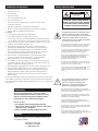
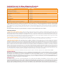
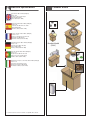
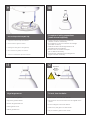
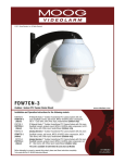
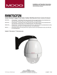
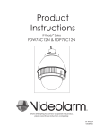
© 2011, Moog Videolarm, Inc. All Rights Reserved
FDW75C8
Fusion Dome (Ultra high PoE)
www.videolarm.com
Installation and Operation Instructions for the following models:
FDW75C8N IP Network Ready 7” Outdoor dome housing with wall mount, clear dome, PoE
input, heater/blower, fan
FDP75C8N
IP Network Ready 7” Outdoor dome housing with pendant mount, clear dome, PoE
input, heater/blower, fan
FDW75T8N IP Network Ready 7” Outdoor dome housing with wall mount, tinted dome, PoE
input, heater/blower, fan
FDP75T8N
IP Network Ready 7” Outdoor dome housing with pendant mount, tinted dome, PoE
input, heater/blower, fan
Before attempting to connect or operate this product, please read these instructions completely.
81-IN5471
01-31-2012
IMPORTANT SAFEGUARDS
1
Read these instructions.
2
Keep these instructions.
3
Heed all warnings
4
Follow all instructions.
5
Do not use this apparatus near water.
6
Clean only with damp cloth.
7
CAUTION
RISK OF ELECTRIC SHOCK
DO NOT OPEN
Do not block any of the ventilation openings. Install in accordance with the
manufacturers instructions.
8
9
SAFETY PRECAUTIONS
Cable Runs- All cable runs must be within permissible distance.
CAUTION: TO REDUCE THE RISK OF
ELECTRIC SHOCK, DO NOT REMOVE
COVER ( OR BACK). NO USER- SERVICEABLE PARTS INSIDE. REFER SEVICING
TO QUALIFIED SERVICE PERSONNEL.
Mounting - This unit must be properly and securely mounted to a supporting
structure capable of sustaining the weight of the unit.
Accordingly:
a. The installation should be made by a qualified installer.
b. The installation should be in compliance with local codes.
c. Care should be exercised to select suitable hardware to install the unit, taking into
account both the composition of the mounting surface and the weight of the unit.
10 Do not install near any heat sources such as radiators, heat registers, stoves, or other
apparatus ( including amplifiers) that produce heat.
11 Do not defeat the safety purpose of the polarized or grounding-type plug. A
polarized plug has two blades with one wider than the other. A grounding type
plug has two blades and a third grounding prong. The wide blade or the third
prong are provided for your safety. When the provided plug does not fit into your
outlet, consult an electrician for replacement of the obsolete outlet.
12 Protect the power cord from being walked on or pinched particularly at plugs,
convenience receptacles, and the point where they exit from the apparatus.
13 Only use attachment/ accessories specified by the manufacturer.
14 Use only with a cart, stand, tripod, bracket, or table specified by the manufacturer,
or sold with the apparatus. When a cart is used, use caution when moving the cart/
apparatus combination to avoid injury from tip-over.
15 Unplug this apparatus during lighting storms or when unused for long periods of time.
16 Refer all servicing to qualified service personnel. Servicing is required when the
apparatus has been damaged in any way, such as power-supply cord or plug is
damaged, liquid has been spilled of objects have fallen into the apparatus, the
The lightning flash with an arrowhead symbol,
within an equilateral triangle, is intended to
alert the user to the presence of non-insulated
“dangerous voltage” within the product’s
enclosure that may be of sufficient magnitude
to constitute a risk to persons.
Este símbolo se piensa para alertar al usuario a la presencia
del “voltaje peligroso no-aisIado” dentro del recinto de los
productos que puede ser un riesgo de choque eléctrico.
Ce symbole est prévu pour alerter I’utilisateur à la presence
“de la tension dangereuse” non-isolée dans la clôture de
produits qui peut être un risque de choc électrique.
Dieses Symbol soll den Benutzer zum Vorhandensein der
nicht-lsolier “Gefährdungsspannung” innerhalb der
Produkteinschließung alarmieren die eine Gefahr des
elektrischen Schlages sein kann.
Este símbolo é pretendido alertar o usuário à presença “di
tensão perigosa non-isolada” dentro do cerco dos produtos
que pode ser um risco de choque elétrico.
Questo simbolo è inteso per avvertire I’utente alla presenza
“di tensione pericolosa” non-isolata all’interno della
recinzione dei prodotti che può essere un rischio di scossa
elettrica.
apparatus has been exposed to rain or moisture, does not operate normally, or
has been dropped.
Be sure to periodically examine the unit and the supporting structure to make sure that the integrity
of the installation is intact. Failure to comply with the foregoing could result in the unit separating
from the support structure and falling, with resultant damages or injury to anyone or anything struck
by the falling unit.
UNPACKING
Unpack carefully. Electronic components can be
damaged if improperly handled or dropped. If an item
appears to have been damaged in shipment, replace
it properly in its carton and notify the shipper.
Be sure to save:
1 The shipping carton and packaging material.
They are the safest material in which to make future
shipments of the equipment.
2 These Installation and Operating Instructions.
SERVICE
If technical support or service is needed, contact us at
the following number:
TECHNICAL SUPPORT
AVAILABLE 24 HOURS
1 - 800 - 554 -1124
The exclamation point within an equilateral
triangle is intended to alert the user to
presence of important operating and
maintenance (servicing) instructions in the
literature accompanying the appliance.
Este símbolo del punto del exclamation se piensa para
alertar al usuario a la presencia de instrucciones importantes
en la literatura que acompaña la aplicación.
Ce symbole de point d’exclamation est prévu pour alerter
l’utilisateur à la presence des instructions importantes dans
la littérature accompagnant l’appareil.
Dieses Ausruf Punktsymbol soll den Benutzer zum
Vorhandensein de wichtigen Anweisungen in der Literatur
alarmieren, die das Gerät begleitet.
Este símbolo do ponto do exclamation é pretendido alertar o
usuário à presença de instruções importantes na literatura
que acompanha o dispositivo.
Questo simbolo del punto del exclamaton è inteso per
avvertire l’utente alla presenza delle istruzioni importanti nella
letteratura che accompagna l'apparecchio.
Limited Warranty for Moog Videolarm Products
Moog Videolarm warrants these products to be free from defects in material or workmanship as follows:
PRODUCT CATEGORY
PARTS \ LABOR
All Enclosures and Electronics*
Five
Poles/PolEvators™/CamEvator
Three (3) Years
Warrior Series™/Q-View™/IR Illuminators
Five
(5) Years
SView Series™
Five
(5) Years **6 months if used in auto scan/tour operation
Controllers
Five
(5) Years
Power Supplies
Five
(5) Years
EcoKit
Three (3) Years
Accessory Brackets
Five
Liberty Dome
Three (3) Years
*DeputyDome™, NiteTrac™, Igloo Dome, PurgeDome™
Three (3) Years **6 months if used in auto scan/tour operation
(5) Years
(5) Years
During the labor warranty period, to repair the Product, Purchaser will either return the defective product, freight prepaid, or deliver it to Moog Videolarm
Inc. Decatur GA. The Product to be repaired is to be returned in either its original carton or a similar package affording an equal degree of protection with
a RMA # (Return Materials Authorization number) displayed on the outer box or packing slip. To obtain a RMA# you must contact our Technical Support
Team at 800.554.1124, extension 101. Moog Videolarm will return the repaired Product freight prepaid to Purchaser. Moog Videolarm is not obligated to
provide Purchaser with a substitute unit during the warranty period or at any time. After the applicable warranty period, Purchaser must pay all labor and/or
parts charges.
The limited warranty stated in these product instructions is subject to all of the following terms and conditions.
TERMS AND CONDITIONS
1. NOTIFICATION OF CLAIMS: WARRANTY SERVICE: If Purchaser believes that the Product is defective in material or workmanship, then written notice with an
explanation of the claim shall be given promptly by Purchaser to Moog Videolarm. All claims for warranty service must be made within the warranty period.
If after investigation Moog Videolarm determines the reported problem was not covered by the warranty, Purchaser shall pay Moog Videolarm for the cost of
investigating the problem at its then prevailing per incident billable rate. No repair or replacement of any Product or part thereof shall extend the warranty period
of the entire Product. The specific warranty on the repaired part only shall be in effect for a period of ninety (90) days following the repair or replacement of that
part or the remaining period of the Product parts warranty, whichever is greater.
2. EXCLUSIVE REMEDY: ACCEPTANCE: Purchaser’s exclusive remedy and Moog Videolarm’s sole obligation is to supply (or pay for) all labor necessary to repair any
Product found to be defective within the warranty period and to supply, at no extra charge, new or rebuilt replacements for defective parts.
3. EXCEPTIONS TO LIMITED WARRANTY: Moog Videolarm shall have no liability or obligation to Purchaser with respect to any Product requiring service during the
warranty period which is subjected to any of the following: abuse, improper use, negligence, accident, lightning damage or other acts of God (i.e., hurricanes,
earthquakes), modification, failure of the end-user to follow the directions outlined in the product instructions, failure of the end-user to follow the maintenance
procedures recommended by the International Security Industry Organization, written in product instructions, or recommended in the service manual for the
Product. Furthermore, Moog Videolarm shall have no liability where a schedule is specified for regular replacement or maintenance or cleaning of certain parts
(based on usage) and the end-user has failed to follow such schedule; attempted repair by non-qualified personnel; operation of the Product outside of the
published environmental and electrical parameters, or if such Product’s original identification (trademark, serial number) markings have been defaced, altered,
or removed. Moog Videolarm excludes from warranty coverage Products sold AS IS and/or WITH ALL FAULTS and excludes used Products which have not
been sold by Moog Videolarm to the Purchaser. All software and accompanying documentation furnished with, or as part of the Product is furnished “AS IS”
(i.e., without any warranty of any kind), except where expressly provided otherwise in any documentation or license agreement furnished with the Product. Any
cost associated with removal of defective product and installation of replacement product is not included in this warranty.
4. PROOF OF PURCHASE: The Purchaser’s dated bill of sale must be retained as evidence of the date of purchase and to establish warranty eligibility.
DISCLAIMER OF WARRANTY
EXCEPT FOR THE FOREGOING WARRANTIES, Moog Videolarm HEREBY DISCLAIMS AND EXCLUDES ALL OTHER WARRANTIES, EXPRESS OR IMPLIED,
INCLUDING, BUT NOT LIMITED TO ANY AND/OR ALL IMPLIED WARRANTIES OF MERCHANTABILITY, FITNESS FOR A PARTICULAR PURPOSE AND/OR
ANY WARRANTY WITH REGARD TO ANY CLAIM OF INFRINGEMENT THAT MAY BE PROVIDED IN SECTION 2-312(3) OF THE UNIFORM COMMERCIAL
CODE AND/OR IN ANY OTHER COMPARABLE STATE STATUTE. Moog Videolarm HEREBY DISCLAIMS ANY REPRESENTATIONS OR WARRANTY THAT
THE PRODUCT IS COMPATIBLE WITH ANY COMBINATION OF NON-Moog Videolarm PRODUCTS OR NON-Moog Videolarm RECOMMENDED PRODUCTS
PURCHASER MAY CHOOSE TO CONNECT TO THE PRODUCT.
LIMITATION OF LIABILITY
THE LIABILITY OF Moog Videolarm, IF ANY, AND PURCHASER’S SOLE AND EXCLUSIVE REMEDY FOR DAMAGES FOR ANY CLAIM OF ANY KIND
WHATSOEVER, REGARDLESS OF THE LEGAL THEORY AND WHETHER ARISING IN TORT OR CONTRACT, SHALL NOT BE GREATER THAN THE ACTUAL
PURCHASE PRICE OF THE PRODUCT WITH RESPECT TO WHICH SUCH CLAIM IS MADE. IN NO EVENT SHALL Moog Videolarm BE LIABLE TO PURCHASER
FOR ANY SPECIAL, INDIRECT, INCIDENTAL, OR CONSEQUENTIAL DAMAGES OF ANY KIND INCLUDING, BUT NOT LIMITED TO, COMPENSATION,
REIMBURSEMENT OR DAMAGES ON ACCOUNT OF THE LOSS OF PRESENT OR PROSPECTIVE PROFITS OR FOR ANY OTHER REASON WHATSOEVER.
!
Electrical Specifications
Power POE 56V
Contents of Box
FDW75 POE
Input Power: 100 to 240Vac (Midspan)
Power: 1.3A
Frequency: 50 to 60 HZ output
Camera: POE (55Vdc)
Heater: 56Vdc (max. 40W)
English
Energía de entrada: 100 a 240Vac (Midspan)
Energía: 1.3A
Frecuencia: 50 a 60 hertzios de salida
Cámara: POE (55Vdc)
Calentador: 56Vdc (máximo 40W)
Español
Français
Deutsch
Puissance d'entrée: 100 à 240Vac (Midspan)
Puissance: 1.3A
Fréquence: 50 à 60 hertz de rendement
Appareil-photo: POE (55Vdc)
Réchauffeur: 56Vdc (maximum 40W)
Zugeführte Energie: 100 zu 240Vac (Midspan)
Energie: 1.3A
Frequenz: 50 bis 60 Hz Ausgang
Kamera: POE (55Vdc)
Heizung: 56Vdc (Maximum 40W)
Pendent Model
(ONLY)
Poder de entrada: 100 a 240Vac (Midspan)
Poder: 1.3A
Freqüência: 50 a 60 hertz de saída
Câmera: Ponto de entrada (55Vdc)
Calefator: 56Vdc (máximo 40W)
A
Portuguese
Alimentazione in ingresso di entrata: 100 a 240Vac (Midspan)
Potere: 1.3A
Frequenza: 50 - 60 hertz di uscita
Macchina fotografica: POE (55Vdc)
Riscaldatore: 56Vdc (massimo 40W)
Italiano
B
• Contact customer service for a full list of compatible Axis cameras.
* NOT included with E or 12V models
1
WALL MOUNTING
2
4”-5”
Bracket is designed for 45° conduit fitting (If using the
conduit). Run wire into bracket, secure to wall.
• El soporte se diseña para la guarnición del conducto 45° (si usa el
conducto). Funcione con el alambre en el soporte seguro para
emparedar.
• La parenthèse est conçue pour l'ajustage de précision du conduit 45° (si
à l'aide du conduit). Courez le fil dans la parenthèse bloquée pour murer.
• Haltewinkel ist für Befestigung des Rohres 45° bestimmt (wenn das Rohr
verwendet wird). Lassen Sie Draht in den Haltewinkel laufen, der, um zu
ummauern sicher ist.
• O suporte é projetado para o encaixe da canalização 45° (se usando a
canalização). Funcione o fio no suporte seguro para murar.
• La staffa è progettata per il montaggio del condotto 45° (se per mezzo
del condotto). Faccia funzionare il legare nella staffa sicura per murare.
3
Secure lanyard to lanyard clip.
• Asegure el acollador al clip del acollador.
Trim incoming control & power wires to 4”- 5”,
for either wall or pendent bracket.
• & entrante del control del ajuste; accione los alambres a 4” - 5”, para
la pared o el soporte pendiente.
• & entrant de commande d'équilibre ; actionnez les fils à 4 » - 5 », pour
le mur ou la parenthèse en suspens.
• Ankommendes & Steuer der Ordnung; antreiben Sie Drähte bis 4“ - 5“,
entweder für Wand oder pendent Haltewinkel r.
• & entrante do controle da guarnição; pnha fios a 4” - 5”, para a
parede ou o suporte pendent.
• & ricevuto di controllo della disposizione; alimenti i legare a 4„ - 5„,
per la parete o la staffa pendent.
4
Complete ALL wiring connections.
• Termine TODAS LAS conexiones del cableado.
• Accomplissez TOUS LES raccordements de câblage.
• Fixez la lanière à l'agrafe de lanière.
• Schließen Sie ALLE Verdrahtungsanschlüsse ab.
• Termine TODAS AS conexões da fiação.
• Befestigen Sie Abzuglinie an Abzuglinieclip.
• Fixe o colhedor ao grampo do colhedor.
• Assicuri la cordicella alla clip della cordicella.
• Completi TUTTI I collegamenti dei collegamenti.
5
!
Important
Gasket
Must be in
place
Align large arrows.
• Alinee las flechas grandes.
6
To lock, turn clockwise.
• Para trabarse, dar vuelta a la derecha.
• Pour fermer à clef, tourner dans le sens des aiguilles d'une montre.
• Alignez les grandes flèches.
• Zu sich verriegeln, nach rechts drehen.
• Para travar, para girar no sentido horário.
• Richten Sie große Pfeile aus.
• Per per chiudere, girare in senso orario.
• Alinhe grandes setas.
• Allini le grandi frecce.
7
8
FOR PENDENT/
WALL MOUNTING
4”-5”
Secure with ¼” Allen wrench.
• Asegure con la llave Allen del ¼”.
• Fixez clé Allen avec de ¼ ».
• Sichern Sie mit ¼“ Inbusschlüssel.
• Fixe com chave Allen do ¼ de”.
• Fissi con chiave di Allen del ¼„.
Trim incoming control and power wires to 4-5” for
either wall or pendent bracket.
• Ajuste los alambres entrantes del control y de la energía a
4-5” para la pared o el soporte pendiente.
• Équilibrez les fils entrants de commande et de puissance à 4-5
» pour le mur ou la parenthèse en suspens.
• Trimmen Sie ankommende Steuer- und Energiendrähte bis
4-5“ entweder für Wand oder pendent Haltewinkel.
• Apare fios entrantes do controle e do poder a 4-5” para a
parede ou o suporte pendent.
• Assetti i legare ricevuti di potere e di controllo a 4-5„ per la
parete o la staffa pendent.
9
Secure lanyard to lanyard clip.
• Asegure el acollador al clip del acollador.
• Fixez la lanière à l'agrafe de lanière.
• Befestigen Sie Abzuglinie an Abzuglinieclip.
• Fixe o colhedor ao grampo do colhedor.
• Assicuri la cordicella alla clip della cordicella.
11
10
Complete all wiring connections
(coax wire not supplied).
• Termine todas las conexiones del cableado
(alambre coaxil no suministrado).
• Accomplissez tous les raccordements de câblage
(fil coaxial non fourni).
• Schließen Sie alle Verdrahtungsanschlüsse ab
(koaxialer Draht nicht geliefert).
• Termine todas as conexões da fiação
(fio co-axial não fornecido).
• Completi tutti i collegamenti dei collegamenti
(legare coassiale non fornito).
12
Important
Gasket
Must be in
place
!
Align large arrows.
To lock, turn clockwise.
• Alinee las flechas grandes.
• Para trabarse, dar vuelta a la derecha.
• Alignez les grandes flèches.
• Pour fermer à clef, tourner dans le sens des aiguilles d'une
montre.
• Richten Sie große Pfeile aus.
• Alinhe grandes setas.
• Allini le grandi frecce.
• Zu sich verriegeln, nach rechts drehen.
• Para travar, para girar no sentido horário.
• Per per chiudere, girare in senso orario.
13
Secure with ¼” Allen wrench.
• Asegure con la llave Allen del ¼”.
• Fixez clé Allen avec de ¼”.
• Sichern Sie mit ¼“ Inbusschlüssel.
• Fixe com chave Allen do ¼ de”.
• Fissi con chiave di Allen del ¼”.
14
!
To loosen - unscrew bolts ½” turn counter
clockwise.
• Para aflojar - desatornille a la derecha contrario de la vuelta
del ½ de los pernos”.
• Pour se desserrer - dans le sens des aiguilles d'une montre de
tour dévissez de boulons ½ » contre-.
• Um sich zu lösen - schrauben Sie Schraubbolzen ½“
Umdrehungs-Gegenrechtses herum ab.
• Para afrouxar - desaparafuse sentido horário contrário volta
do ½ dos parafusos da”.
• Per allentare - sviti in senso orario di girata del ½ dei bulloni„
contro.
CAMERA: SONY SNC-RS44N
15
16
24VAC Power
RJ45
Attach the SNC RH124 ceiling plate to 1” (25mm)
spacers in housing
Connect control and power wires to camera
base, (see Sony camera instructions)
• Ate la placa del techo de SNC RH124” a los espaciadores 1 (de 25m
m) en la cubierta
• Conecte el control y accione los alambres a la base de la cámara,
(véase las instrucciones de la cámara de Sony)
• Attachez le plat de plafond de SNC RH124 » aux entretoises 1 (de
25mm) dans le logement
• Reliez la commande et actionnez les fils à la base d'appareil-photo,
(voir les instructions d'appareil-photo de Sony)
• Bringen Sie SNC RH124 Deckenplatte zu“ (25mm) Distanzscheiben 1 im
Gehäuse an
• Schließen Sie Steuerung an und treiben Sie Drähte zur Kameraunterseite an, (sehen Sie Sony-Kameraanweisungen)
• Una a placa do teto de SNC RH124” aos espaçadores 1 (de 25mm)
na carcaça
• Conecte o controle e pnha fios à base da câmera, (veja instruções
da câmera de Sony)
• Attacchi il piatto del soffitto di SNC RH124„ ai distanziatori 1 (di 25mm)
in alloggiamento
• Colleghi il controllo ed alimenti i legare alla base della macchina
fotografica, (vedi le istruzioni della macchina fotografica di Sony)
17
Attach base plate to ceiling plate with hardware
provided with camera
18
Attach main connector and install camera to
base plate. Secure locking pins
• El embase de la fijación a la placa del techo con hardware
proporcionó la cámara
• Ate el conectador principal e instale la cámara al embase. Asegure
las clavijas de cierre
• L'embase d'attache au plat de plafond avec le matériel a fourni en
appareil-photo
• Attachez le connecteur principal et installez l'appareil-photo sur
l'embase. Fixez les chevilles de verrouillage
• Grundplatte der Befestigungs zur Deckenplatte mit Hardware versah
mit Kamera
• Bringen Sie Hauptverbindungsstück an und bringen Sie Kamera zur
Grundplatte an. Sichern Sie Sicherungsstifte
• A placa baixa do anexo à placa do teto com ferragem forneceu
com a câmera
• Una o conector principal e instale a câmera à placa baixa. Fixe os
pinos de travamento
• La base di appoggio dell'attaccatura al piatto del soffitto con fissaggi
ha fornito la macchina fotografica
• Attacchi il connettore principale ed installi la macchina fotografica
alla base di appoggio. Fissi i perni di bloccaggio
CAMERA: PANASONIC WV-NS202A, WV-SC385
19
20
Screw the 3” (75mm) spacers to base bracket
as shown.
Attach the camera mounting plate to
the spacers.
• Atornille los 3” espaciadores (de 75m m) para basar el soporte como
se muestra.
• Ate la pletina de la cámara a los espaciadores.
• Vissez les 3 » entretoises (de 75mm) pour baser la parenthèse comme
montrée.
• Attachez le plat de support d'appareil-photo aux entretoises.
• Bringen Sie die KameraMontageplatte zu den Distanzscheiben an.
• Schrauben Sie die 3“ (75mm) Distanzscheiben, um Haltewinkel wie
gezeigt zu gründen.
• Una a placa de montagem da câmera aos espaçadores.
• Parafuse os 3” espaçadores (de 75mm) para basear o suporte como
mostrado.
• Attacchi il giunto di supporto della macchina fotografica ai
distanziatori.
• Avviti i 3„ distanziatori (di 75mm) per basare la staffa come indicata.
21
22
Twist on the camera clockwise to the
mounting plate.
Attach safety lanyard and secure camera with
set screw.
• Tuerza en la cámara a la derecha a la pletina.
• Ate el acollador de la seguridad y asegure la cámara con el tornillo
de presión.
• Tordez sur l'appareil-photo dans le sens des aiguilles d'une montre au
plat de support.
• Verdrehen Sie sich auf der Kamera nach rechts zur Montageplatte.
• Torça na câmera no sentido horário à placa de montagem.
• Torca sulla macchina fotografica in senso orario al giunto di supporto.
• Attachez la lanière de sûreté et fixez l'appareil-photo avec la vis de
réglage.
• Bringen Sie Sicherheitsabzuglinie an und sichern Sie Kamera mit
Klemmschraube.
• Una o colhedor da segurança e fixe a câmera com parafuso de
fixação.
• Attacchi la cordicella di sicurezza e fissi la macchina fotografica con
la vite di arresto.
23
PoE Input
NOTE: Fan will take 30 sec. to start after power is applied.
PoE Input
• Entrada del PoE NOTA: El ventilador tardará el sec 30. para
comenzar después de energía es aplicado.
• Entrée de PoE NOTE : Le ventilateur prendra sec 30. pour
commencer après puissance est appliqué.
• PoE-Eingang ANMERKUNG: Ventilator nimmt sek 30. zu nach
Energie zu beginnen ist angewandt.
• Entrada do ponto de entrada NOTA: O ventilador tomará o
segundo 30. para começar após o poder é aplicada.
• Input di PoE NOTA: Il ventilatore richiederà sec 30. per cominciare
dopo potere è applicato.
24
1” spacers + (4) ½” spacers (4) corner bosses.
LED
• 1” espaciadores + (4) jefes de la esquina de los espaciadores del ½” (4).
Reset
Button
• 1 » entretoises + (4) patrons faisants le coin des entretoises de ½ » (4).
• 1“ Distanzscheiben + (4) ½“ Eckchefs der Distanzscheiben (4).
• saliências de canto dos espaçadores de 1” espaçadores + (4) ½” 4).
• i distanziatori del 1„ distanziatori + (4) ½„ (4) sporgenze d'angolo.
Network to Camera
25
To maximize power for heater hold reset 1 sec. then release.
“HEAT” LED TURNS OFF when calibration is complete. To return
setting to factory default, hold reset 5 sec. then release.
Reset
• Para maximizar la energía para el calentador celebre el reajuste 1
sec. entonces lance. “CALIENTE” el LED APAGA cuando la
calibración es completa. Para volver el ajuste al defecto de la
fábrica, lleve a cabo el sec del reajuste 5. entonces lance.
• Pour maximiser la puissance pour le réchauffeur tenez la remise
pendant 1 sec. libérez alors. « CHAUFFEZ » la LED S'ÉTEINT quand le
calibrage est complet. Pour renvoyer l'arrangement au défaut
d'usine, tenez sec de la remise 5. libérez alors.
• Um Energie für Heizung zu maximieren halten Sie Zurückstellen 1
sek. geben Sie dann frei. „ERHITZEN Sie“ LED ABSTELLT, wenn
Kalibrierung komplett ist. Um Einstellung zur Fabrikrückstellung
zurückzubringen, halten Sie sek des Zurückstellens 5. geben Sie
dann frei.
• Para maximizar o poder para o calefator prenda a restauração 1
segundo. libere então. “AQUEÇA” o diodo emissor de luz DESLIGA
quando a calibração está completa. Para retornar o ajuste ao
defeito da fábrica, prenda o segundo da restauração 5. libere
então.
• Per elevare il potere per il riscaldatore tenga la risistemazione 1
sec. allora liberi. “RISCALDI„ il LED SPEGNE quando la calibratura è
completa. Per restituire la regolazione a difetto della fabbrica,
tenga sec di risistemazione 5. allora liberi.
26
27
Before
Tab
After
Loop the lanyard around the tab inside the
housing.
Align the arrows on the outside of the dome
and lock.
• Coloque el acollador alrededor de la lengüeta
dentro de la cubierta.
• Faites une boucle la lanière autour de l'étiquette à
l'intérieur du logement.
• Schlingen Sie die Abzuglinie um den Vorsprung
innerhalb des Gehäuses.
• Dê laços no colhedor em torno da aba dentro da
carcaça.
• Colleghi la cordicella in circuito intorno alla
linguetta all'interno dell'alloggiamento.
• Alinee las flechas en el exterior de la bóveda y
trábese.
• Alignez les flèches sur l'extérieur du dôme et
fermez à clef.
• Richten Sie die Pfeile auf der Außenseite der
Haube aus und verriegeln Sie sich.
• Alinhe as setas na parte externa da abóbada e
trave-as.
• Allinei le frecce sulla parte esterna della cupola e
blocchi.
28
29
Fasten down the dome with a Phillips
screwdriver.
Wipe the dome clean.
• Sujete abajo de la bóveda con un destornillador
Phillips.
• Attachez en bas du dôme avec un tournevis
Phillips.
• Befestigen Sie sich hinunter die Haube mit einem
Kreuzkopfschraubenzieher.
• Prenda abaixo a abóbada com uma chave de
fenda Phillips.
• Fissisi giù la cupola con un cacciavite "phillips".
• Limpie la bóveda limpia.
• Essuyez le dôme.
• Wischen Sie die Haube sauber ab.
• Limpe a abóbada limpa.
• Asciughi la cupola.
PB24 Addendum
Additional wires are provided to run power to PB24. Use with connector supplied. Run RJ45 connector
through PB24, wall mount, and connect lead from housing.
• Los alambres adicionales se proporcionan a la energía funcionada con a PB24. El uso con el conectador proveyó.
Funcione con el conectador RJ45 con PB24, emparede el montaje, y conecte el plomo de la cubierta.
• Des fils additionnels sont fournis à la puissance courue à PB24. L'utilisation avec le connecteur a fourni. Courez le
connecteur RJ45 par PB24, murez le bâti, et reliez le fil du logement.
• Zusätzliche Drähte zur Verfügung gestellt zu laufen gelassener Energie zu PB24. Gebrauch mit Verbindungsstück lieferte.
Laufen lassen Sie Verbindungsstück RJ45 durch PB24, ummauern Sie Einfassung und anschließen Sie Blei vom Gehäuse n.
• Os fios adicionais são fornecidos ao poder funcionado a PB24. O uso com conector forneceu. Funcione o conector RJ45
com PB24, mure a montagem, e conecte a ligação da carcaça.
• I legare supplementari sono forniti a potere funzionato a PB24. L'uso con il connettore ha fornito. Faccia funzionare il
connettore RJ45 con PB24, muri il supporto e colleghi il cavo da alloggiamento.
Replacement Parts List
FDW75
14
15
16
13
12
11
10
9
8
7
5
6
4
3
1
2
1
1A
2
3
4
5
5A
6
7
8
9
10
11
12
13
14
15
16
N/S
N/S
N/S
PART NUMBER
FD7C
FD7T
RPFD7501
RPFD703
RPNET02
RPFD072
RPFD072/12
RPFD080
RP3510
RP76VL2008
RPFD040
RPFD2612
RPFD3245
RPGK3356
RP3458
RP3551
RP3606
RP3719
RPPKH2098
RPPKE1100
RPTRAN02
DESCRIPTION
CLEAR REPLACEMENT CAPSULE
TINTED REPLACEMENT CAPSULE
LOWER TRIM RING
DOME CLAMPING RING
NETWORK HGS POWER SUPPLY
24V HEATER
12V HEATER (12VDC MODELS ONLY)
BLOWER
CAMERA BRACKET
PoE BOARD
HOUSING TOP
HOUSING TOP GASKET
WALL/PENDENT ADAPTER
WALL/PENDENT GASKET
LANYARD SET
WM11 WALL MOUNT
PENDENT MOUNT BRACKET
1 1/2 FEMALE /FEMALE COUPLING
BRACKET PACKET ASSEMBLY
ELECTRICAL PACKET ASSEMBLY
110 TO 24VAC WALL TRANSFORMER
Product Registration/Warranty
Thank you for choosing Moog Videolarm. We value your patronage and are solely committed to providing you with the highest
quality products available and superior customer service.
Should a problem arise, rest assure that Moog Videolarm stands behind its products by offering impressive warranty plans: 3 Years on all Housings, Poles,
Power Supplies, and Accessories and 5 Years on camera systems (SView, QView, Warriors), and InfraRed Illuminators.
Register Your Products Online
Take a few moments and validate your purchase via the Online Product Registration Form at
www.videolarm.com/productregistration.jsp
Register your recent Moog Videolarm purchases and benefit from the following:
• Simple and Trouble-Free RMA process
• Added into customer database to receive product updates / news
• Eliminate the need to archive original purchase documents:
Receipts, Purchase Orders, etc…