1
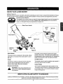
,4U6 2 0 J997
Owner's Manual
CRAFTSMAN°
21" Mulching/Side-Discharge
PUSH LAWN MOWER
Model No.
247.370320
CAUTION: Before using this product,
read this manual and follow all Safety
Rules and Operating Instructions.
Sears, Roebuck and Co., Hoffman
Printed in U.S.A.
Estates, IL 60179, U.S.A.
770-0751M
Page
Content
Content
Page
Warranty Information
2
Maintenance
12
Safe Operation Practices
3
Service & Adjustment
15
Slope Gauge
6
Storage
17
Assembly
7
Trouble-Shooting
19
Operation
9
Parts List
20
Two-Year
Warranty on Craftsman
Lawn Mower
For two years from the date of purchase, when this Craftsman lawn mower is maintained, lubricated, and tuned
up according to the instructions in the owner's manual, Sears will repair, free of charge, any defects in material or
workmanship. If this lawn mower is used for commercial or rental purposes, this warranty applies for only 90 days
from the date of purchase.
This warranty does not cover:
1.
Expendable items which become worn during normal use, such as rotary mower blades, blade adapters,
belts, air cleaners and spark plug.
2.
Repairs necessary because of operator abuse or negligence, including bent crankshafts and the failure to
maintain equipment according to the instructions contained in the owner's manual.
WARRANTY SERVICE IS AVAILABLE BY RETURNING THE CRAFTSMAN LAWN MOWER TO THE
NEAREST SEARS SERVICE CENTER IN THE UNITED STATES. THIS WARRANTY APPLIES ONLY WHILE
THIS PRODUCT IS IN USE IN THE UNITED STATES.
This warranty gives you specific legal rights, and you may also have other rights which vary from state to state.
Sears, Roebuck and Co., D/817WA, Hoffman Estates, IL 60179
These accessories were
available when the lawn
mower was purchased, They
are also available at most
Sears retail outlets, and
service centers. Most Sears
stores can order repair parts
for you when you provide the
model number of your lawn
mower.
PRODUCT
Air Filter Spark Plug
Muffler
Engine Oil Stabilizer
Gas Can
SPECIFICATIONS
Horsepower:
5.5 H.P.
Engine Oil
27 oz. SAE 30 oil
Fuel Capacity:
1.5 quarts
Spark Plug
J19LM
_--_
" _.,._
Wheels
Blade
Grass Catcher
, Please record model number, serial number, and
date of purchase here for future reference, You will
find this information on the model plate located on
the cutting deck of your mower.
Model Number .........................................................
Serial Number ...........................................................
Gap .030 inches
Date of Purchase ......................................................
2
This symbol points out important safety instructions which, if not followed, could endanger the personal safety and/or property of yourself and others. Read and follow all instructionsin this manual before
attempting to operate your lawn.mower. Failureto comply with these instructionsmay resultin personal
injury.When you see this symbol--heed its warning.
r
I ,_
I _.-
nANnER--
lu
Your lawn mower was built to be operated according to the rules for safe operation in this
manual. As with any type of power equipment, carelessness or error on the part of the operator
' can result in serious injury.If you violate any of these rules, you may cause serious injury to
yourself or others.
This unitis equipped with an internal combustion engine and should not be used on or near any unimproved
forest-covered, brush-covered or grass-covered land unless the engine's exhaust system is equipped with a
spark arrester meeting applicable local or state laws (if any). If a spark arrester iS used, it should be
maintained in effective working order by the operator.
In the State of California the above is required by law (Section 4442 of the Califomia Public Resources
Code). Other states may have similar laws. Federal laws apply on federal lands. A spark arrester for the
muffler is available through your nearest Sears Authorized Service Center (See the REPAIR PARTS section
of this manual.)
WARNING: The engine exhaust from this product contains chemicalsknownto the State of California to
cause cancer, birth defects or other reproductiveharm.
GENERAL
OPERATION
or any others allowed in the area.
Thoroughlyinspect the area where the equipment
is to be used. Remove all stones, sticks, wire,
bones, toys and other foreign objects which could
be picked up and thrown by the mower in any
direction and cause serious personal injury to the
operator or any others allowed in the area. Plan
your mowing pattern to avoid dischargeof material
toward roads, sidewalks, bystanders and the like.
To help avoid a thrown object's injury, keep
children, bystanders and helpers at least 75 feet
from the mower while it is in operation.
Always wear safety glasses or safety goggles
during operation or while performing an adjustment
or repair, to protect eyes from foreign objects that
may be thrown from the machine in any direction,
Wear sturdy, rough-soled work shoes and closefitting slacks and shirts. Shirts and pants that cover
the arms and legs and steel-toed shoes are
recommended. Do not wear loose fitting clothes or
jewelry. They can be caught in moving parts. Never
operate a unit in bare feet, sandals, slippery or light
weight (e.g. canvas) shoes.
Do not put hands or feet near or under rotating
parts. Keep clear of discharge opening at all times
as the rotatingblade can cause injury.
Many injuries occur as a result of the mower being
pulled over the foot during a fall. Do not hang on to
the mower if you are falling; release the handle
immediately.
Never pull the mower toward you while you are
Read this owner's guide carefully in itsentirety
before attempting to assemble this machine.
Read, understand, and follow all instructions on
the machine and in the manual(s) before
operation. Be completely familiar with the controls
and the proper use of this machine before
operating it. Keep this manual in a safe place for
future and regular reference, and for ordering
replacement parts.
Your rotary mower is a precision piece of power
equipment, not a plaything.Therefore, exercise
extreme caution at all times. Your unit has been
designed to perform one job: to mow grass. Do not
use it for any other purpose.
Never allow children under 14 years old to operate
a power mower. Children 14 years old and over
should only operate mower under close parental
supervision. Only responsible individualswho are
familiar with these rules of safe operation should
be allowed to use your mower.
Keep the area of operation clear of all persons,
particularlysmall children and pets. Stop engine
when they are in the vicinityof your mower to help
prevent blade contact or thrown object injury.
Althoughthe area of operation should be
completely cleared of foreign objects, an object
may have been overlooked and could be
accidentallythrown by the mower in any direction
and cause serious personalinjuryto the operator
3
walking. If you must back the mower away from a
waltor obstruction first look down and behind, and
then follow these steps:
a. Step back from the mower to fully extend
your arms.
b. Be sure you are well balanced with sure
footing.
c. Pull the mower back slowly, no more than
half way toward you.
d. Repeat these steps as needed.
Do not operate the mower while under the
influence of alcohol or drugs.
Do not engage the self-propelled mechanism on
units so equipped while starting engine.
The blade control handle is a safety device. Never
attempt to bypass its operation. Doing so makes
the safety device inoperative and may result in
personal injury through contact with the rotating
blade. The blade control handle must operate
easily in both directions and automatically return
to the disengaged position when released.
Never operate the mower in wet grass. Always be
sure of your footing. A slip and fall can cause
serious personal injury. Keep a firm hold on the
handle and walk, never run. If you feel you are
losing your footing, RELEASE THE BLADE
CONTROL HANDLE IMMEDIATLEY and the
blade will stop rotating within three seconds.
Mow only in daylight or good artificial light.
Stop the blade when crossing gravel drives, walks
or roads.
If the equipment should start to vibrate
abnormally, stop the engine and check
immediately for the cause. Vibration is generally a
warning of trouble.
Shut the engine off and wait until the blade comes
to a complete stop before removing the grass
catcher or unclogging the chute. The cutting
blade continues to rotate for a few seconds after
the engine is shut off. Never place any part of the
body in the blade area until you are sure the blade
has stopped rotating.
Never operate mower without proper guards,
grass catcher, plates or other safety protective
devices in place.
Muffler and engine become hot and can cause a
burn. Do not touch.
Only use accessories approved for this machine
by the manufacturer. Read, understand, and
follow all instructions provided with the approved
accessory.
If situations occur which are not covered in this
manual, use care and good judgment. Contact
your dealer for assistance.
a slopeor hilly area. If the slope isgreater than 15 degrees
as shownon the slopegauge (page 6), do notoperatethis
uniton thatarea or seriousinjurycould result.
DO:
•
•
•
Mow across the face of slopes; never up and
down. Exercise extreme caution when changing
direction on slopes.
Watch for holes, ruts, hidden objects, or bumps.
Tall grass can hide obstacles.
Always be sure of your footing. A slip and fall can
cause serious personal injury. If you feel you are
losing your balance release the blade control
handle immediately and the blade will stop in less
than 3 seconds.
ON MODELS WITH CASTER WHEELS: Lock
both front wheels so they do not pivot while
mowing on the face of slopes. To turn the mower,
depress the handle and raise the front wheels
slightly.
DO NOT:
Do not mow near drop-offs, ditches or
embankments. The operator could lose footing or
balance.
Do not mow slopes greater than 15 degrees as
shown on the slope gauge.
Do not mow on wet grass. Reduced footing could
cause slipping.
ON MOWERS WITH CASTER WHEELS: Do Not
mow on slopes with casters unlocked since the
mower has a tendency to drift down hill.
CHILDREN
Tragicaccidents can occur ff the operator is not alert to the
presence of children. Children are often attracted to the
mower and the mowing activity. Never assume that
children will remain where you last saw them.
•
Keep children out of the mowing area and under
the watchful care of a responsible adult other than
the operator.
Be alert and turn mower off if a child enters the
area.
Before and while moving backwards, look behind
and down for small children or other objects.
Never allow children under age 14 to operate the
mower. Children 14 years of age and above
should read and understand the operation
instructions and safety rules in this manual.
Use extreme care when approaching blind
corners, shrubs, trees, or other objects that may
obscure your vision of a child or hazard.
SERVICE
SLOPE OPERATION
For your safety, use the slope gauge included as part of
this manual to measure slopes before operating this unit on
Use extreme care in handling gasoline and other
fuels. They are extremely flammable and the
vapors are explosive.
Keep all nuts, bolts, and screwstight to be sure
the equipment is in safe workingcondition.
Never tamper with safety devices. Check their
properoperation regularly.
After striking a foreign object, stop the engine,
remove the wire from the spark plug, and
thoroughlyinspectthe mower for any damage.
Repair the damage beforestarting and operating
the mower.
Use only an approved gasoline container.
Never remove gas cap or add fuel while the
engine is running. Allow engine to cool at least
two minutesbefore refueling.
Replace gasolinecap securely and wipe off any
spilled gasolinebefore startingthe engine as it
may cause a fire or explosion.
Extinguishall cigarettes, cigars, pipes and other
sources of ignition.
Never refuelmachine indoorsbecause flammable
vaporswill accumulate in the area.
Never store the machine or fuel container inside
where there is an open flame or spark such as a
gas water heater, space heater, or furnace.
Never run an engine inside a closed area.
To reduce fire hazard, keep mower free of grass,
leaves, or other debris build-up.Clean up oil or
fuel spillage. Allow mower to cool at least 5
minutesbefore storing.
Before cleaning, repairing, or inspecting,make
certainthe blade and all moving parts have
stopped. Disconnectthe spark plug wire, and
keep the wire away from the spark plug to prevent
accidental starting.
Check the blade and engine mounting boltsat
frequent intervalsfor proper tightness.Also,
visually inspectblade for damage (e.g., bent,
cracked or worn). Replace with blade which
meets originalequipment specificationslisted in
this manual.
Never attempt to make a wheel or cuttingheight
adjustment while the engine is running.
Grass catcher componentsare subject to wear,
damage and deterioration,which could expose
moving parts or allow objectsto be thrown. For
safety protection,frequently check components
and replace with manufacturer's recommended
parts,when necessary.
Mower blades are sharpand can cut. Wrap the
blade(s) or wear gloves, and use extra caution
when servicingthem.
Do not change the engine governorsetting or
overspeed the engine. Excessiveengine speeds
are dangerous.
YOUR RESPONSIBILITY
Restrict the use of this power machineto
persons who read, understand and follow the
warnings and instructions in this manual and
on the machine.
Following are representations of the safety labels on
your lawn mower. Maintain safety while operating the
mower. Please have the part number ready when reordering safety labels.
Part no. 777-5270
DANGER
Part no. 777-1584
SAVE THESE INSTRUCTIONS
FOR FUTURE REFERENCE.
Part no. 777-1595C
5
_)
Z
m_
SIGHT AND HOLD THIS LEVEL WITH A VERTICAL TREE
!
Ii.q
_._
_"
_" _ _. _.
,
_li_
;
:
, -._:
'-
A
I'_
I_
- __Okoo
_
:
A CORNER
OR AOF
FENCE
A BUILDING
POST
'
il '
,_
POWER POLE
.
,,
-
°II::
_
,_
6
411i,m,,/ill,
iu_
u.I U.I
a. _
--_ __ _
"'
"'
€/)a.
O
Do not mow on inclines with a slope in excess of 15 degrees (a rise of approximately 2-112 feet every 10 feet).
A riding mower could overturn and cause serious injury. If operating a walk-behind mower on such a slope, it
is extremely difficult to maintain your footing and you could slip, resulting in serious injury.
Operate RIDING mowers up and down slopes, never across the face of slopes.
Operate WALK-BEHIND mowers across the face of slopes, never up and down slopes.
REMOVING
•
•
UNIT FROM CARTON
mower and/or front or behind the mower is observed
from the operating position.
Remove staples, break glue on top flaps, or cut
tape at carton end and peel along top flap to
open carton.
Remove loose parts if included with unit (i.e.,
owner's manual, etc.). See Figure 1.
LOOSE PARTS
a. Side Discharge Chute
b. Owner's Manual
c. A Bottle of Engine Oil
1. Remove manuel & loose parts
TOOLS REQUIRED
a. Pair of Pliers
b. Funnel
DISCONNECTING
•
Before setting up your lawn mower, disconnect
the spark plug wire from the spark plug, and
ground it against the engine. See Figure 2.
Attach rubber boot to a bolt on the engine to
ground.
•
Spark
Plug__
Wire
2. Roll unit out
Figure
•
•
•
1
SPARK PLUG
I
Cut along dotted lines and lay carton down flat.
Remov_ packing material.
Roll or slide unit out of carton. Check carton
thoroughly for loose parts. See Figure 1.
Rubber BootF_"
Note: Make sure not to crimp the cables while
removing the loose parts or the entire unit from the
carton.
Plug
Figure 2
ASSEMBLING
IMPORTANT: This unit is shipped without gasoline
or oil in the engine. Be certain to service engine with
gasoline and oil before operating your mower.
HANDLE
Raise the lower handle in the direction shown in
Figure 3A, The lower handle should snap into
place.
NOTE: Reference to right or left hand side of the
Weld Pin
Figure 3
7
Note: Make sure to route the cables inside the lower
handle. Also do not crimp the cables while rifting the
handle up,
mulching cover to the deck. See Figure 5A.
Keep the cover in a safe place for future use.
Save the wing nuts.
Ptace the side discharge chute on the deck in
place of the mulching cover so that the top
flange of the discharge chute goes under the
deck. See Figure 5B.
Align the three slots on the chute with the
hardware slots on the deck.
For shipping purposes, the hairpin clip is placed in the
outer hole of the weld pin on the lower handle.
•
Remove the hairpin clip from the outer hole of
the weld pin,
•
Using a pair of pliers, insert the hairpin clip into
the inner hole in the weld pin. Repeat on other
side. See Figure 3 inset.
•
Raise the upper handle in the direction shown in
Figure 3B. Tighten the wing nuts which are
already on the handle.
•
Attach the cables to the lower handle with the
two cable ties already on the lower handle. Pull
tight the cable ties and cut off the extra.
ATTACHING
STARTER
Secure with the wing nuts earlier removed.
Tighten the wing nuts.
Mulching
Cover
ROPE
The rope guide is already attached to the right side of
the upper handle of your mower. See Figure 4.
•
With the spark plug wire disconnected and
grounded, hold the blade control handle against the
upper handle, and pull the starter rope out of the
engine.
•
Slip the rope through the rope guide. Tighten the
wing nut holding the rope guide to the upper
handle.
Recoil
Starter
Wing Nut
/
_Hendle
Side Discharge
Chute
Rope Guide
Lower Handle
Figure 4
ATTACHING
Top
DISCHARGECHUTE
I
Align the slot
here (only two
shown)
Your lawn mower was shipped as a mulcher.
Remove the mulching cover and attach the side
discharge chute for discharging grass clippings.
•
Remove three plastic wing nuts holding the
Figure 5
8
KNOW YOUR LAWN MOWER
(Refer to Figure 6.)
Read this owner's manual and safety rules before operating your lawn mower. Compare the illustrations in Figure
6 with your lawn mower to familiarize yourself with the location of various controls and adjustments. Save this
The operation of any lawn mower can result in foreign objects being thrown into the operator's
eyes and causing severe eye damage. Always wear safety glasses while operating the
manual for future reference.
mower, or while performing any adjustments or repairs on it.
Blade Control Handle
Oil Fill
Gas Tank
Recoil Starter
Engine
Caster Lock
Mulching
Cover
Thr_
Control
Primer
Plug
Figure 6
Chute
Recoil Starter
The recoil starter is attached to the handle. Stand
behind the unit and pull the recoil starter to start
the unit.
The blade control handle is located on the upper
handle of the mower. The blade control handle must
be depressed in order to operate the unit. Release the
blade control handle to stop the engine and blade.
Primer
Throttle Control
The primer is used to pump gas into the carburetor.
Use it to start a cold engine, but do not use it to
restart a warm engine after short shutdown.
The throttle control is used to regulate engine speed. It
cannot be used to stop the engine.
Blade Control Handle
Your mower is equipped with caster wheels in front.
The casters can be locked in a straight ahead position
for mowing on hills, or can be left unlocked to swivel
freely on level ground.
,_
Caster Wheels
WARNING:
control
mechanism
is a
safety device. This
Never
attempt
to bypass
its operations.
MEETS CPSC BLADE SAFETY STANDARDS
Craftsman Walk-Behind Lawn Mowers conform to the safety standards of the American National Standards Institute
and the U.S. Consumer Product Safety Commission.
9
STOPPING
ENGINE
NOTE: Although multi-viscosity oils (5W30, 10W30,
etc.) improve starting in cold weather, these
multiviscosity oils will result in increased oil
consumption when used above 32°F. Check the oil
level more frequently to avoid possible engine
damage from running low on oil.
Release blade control handle to stop the
engine and the blade.
Disconnect spark plug wire and move away
from spark plug to prevent accidental starting.
Gasoline
again
refer to Before
the safety
rules
pages
3-5
WARNING:
using
youron
lawn
mower,
of this manual. Always be careful.
is
running
or hot.
not smoke
when
filling
Never
fill fuel
tankDo
indoors,
or when
engine
fuel tank.
GAS AND OIL FILL-UP
•
(Referto
Figure 7)
•
•
Oil (Packed with unit)
Only use high quality detergent oil rated with
API service classification SF, SG or SH. Select
the oil's viscosity grade according to your
expected operating temperature. Follow the
chart below.
Clean area around fuel cap. Remove cap. See
Figure 7.
Use a funnel to prevent spillage.
Pour approximately 1.5 quarts of fresh, regular
grade, unleaded gasoline slowly to the fuel tank.
IMPORTANT: Never mix engine oil with gasoline.
Fill tank to 1/2" below the bottom of the filler
neck. Wipe any fuel spillage. Do not fill fuel tank
completely. Provide space for fuel expansion.
STARTING
Colder
_ll-5W30
32°F _
I
ENGINE
Warmer
SAE 3O
the
operator Be
is standing
nearother
the lawn
WARNING:
sure no one
than
mower while starting or operating.
Oil Viscosity Grade Chart
NOTE: To prevent the unit from sliding, place your
foot firmly against the tire.
Use SAE30 oil; do not use 10W40 oil.
Fill oil sump and check the oil level. See Figure 7.
a. Position the mower on level ground.
b. Clean area around oil fill plug.
c. Remove oil fill plug and dipstick.
d. Wipe dipstick clean, insert it into oil fill hole
and tighten securely.
e. Remove dipstick and check oil level. If the
oil is not upto FULL mark on the dipstick,
pour recommended oil through the oil fill
and check the level again.
Install oil fill plug and dipstick, tighten securely.
Attach spark plug wire to spark plug. Make
certain the metal cap on the end of the spark
plug wire is fastened securely over the metal tip
on the spark plug.
&
Never run engine indoors or in enclosed,
poorly ventilated areas. Engine exhaust
contains carbon monoxide, an odorless and
deadly gas.
Keep hands, feet, hair and loose clothing
away from any moving parts on engine and
lawn mower.
Move throttle control to FAST position.
Push primer three times. See Figure 8. Wait
about two seconds between each push. In cold
weather around 55 ° F or below, prime five
times. Do not prime to restart a warm engine
after a short shutdown.
Fill oil here
Grasp starter handle and pull rope out slowly
until engine reaches the start of compression
cycle (rope will pull slightly harder at this point).
See Figure 8. Let the rope rewind slowly.
Pull rope with a rapid, continuous, full arm
Fill gas here
Figure 7
10
stroke.Keepingafirmgriponthestarter
handle,lettheropereturntothestarterslowly.
•
Aftertheenginestarts,movethrottlecontrolto
desiredenginespeed.
Note:ff engine fails to start after three pulls, repeat
USING YOUR LAWN MOWER
Your mower is designed to operate as a mulching or a
side discharge unit.
•
For converting from a mulcher to a side
discharge unit, refer to instructionson page 8 of
this manual.
steps,?, 3, and4.
4. Squeeze blade control handle
•
•
5. Pull
rope
1. Attach
control to FAST
•
plug
3. Prime three
Figure 8
LOCKING CASTERS
•
If you are cutting grass on a slope, always lock the
front wheel casters of your mower for straight ahead
operation. On level ground you may leave the casters
unlocked to pivot freely.
To turn the mower on a slope with casters locked,
depress the handle and raise the front wheels slightly,
•
To lock caster: Lift and place the lock pin in the
larger hole on each caster. See Figure 9.
•
To unlock caster: Lift and place the lock pin in
the smaller hole to allow casters to rotate freely.
See figure 9.
•
Locked
"t
•
For converting from a side discharge unit to a
mulcher, replace the side discharge chute with
the mulching cover. Do not operate mower
without the mulching cover or the discharge
chute properly installed and tightly secured.
Be sure that lawn is clear of stones, sticks, wire,
or other objects which could damage lawn
mower or engine. Such objects could be
accidently thrown by the mower in any direction
and cause serious personal injury to the
operator and others.
Forbestresults, donotcut wetgrassbecause
it tends to stick to the underside of the mower,
preventing proper discharge of grass clippings,
and could cause you to slip and fall. New grass,
thick grass or wet grass may require a narrower
cut. Blade speed should be adjusted to the
condition of the lawn.
The best mowing pattern is one that allows the
clippings to discharge towards the uncut part of
the lawn. This permits recurring of the clippings
to further pulverize them. When cutting high
weeds, discharge towards cut portion, then
recut at right angles to first direction.
Forahealthylawn, alwayscutoffone-thirdorless
of the total length of the grass. Lawn should be
cut in the fall as long as there is growth.
This mower is designed to be operated at full
throttle to give you the best cutand do the most
effective job of bagging the cut grass.
WARNING:
If you strike a foreign object,
stop
the engine.
Remove spark
plug
from spark
plug, thoroughly
inspect
thewire
Unlocked
osition
mower for any damage. Repair the damage
Extensive vibration of the mower during
operation is an indication of damage. The
unit should be promptly inspected and
repaired.
before restarting and operating the mower.
Posltio_
HEIGHT ADJUSTMENT
Refer to height adjustments section of this manual on
page 16 for instruction on how to adjust the cutting
height and the handle height.
For best results in mowing, keep the cutting height
position high until it is determined which height is best
for your lawn.
Figure 9
&
WARNING: Do not mow on slopes with
casters unlocked since the mower can drift
downhill.
11
GENERAL
RECOMMENDATIONS
Disconnect spark plug wire.
Drain the gasoline from the lawn mower, or
place a piece of plastic under the gas cap.
Tip the mower so that it rests on the housing.
Keep the side with the air cleaner facing up.
Hold it firmly.
Scrape clean the underside of the deck with a
suitable tool.
Put the mower back on its wheels on the
ground. If you had put plastic under the gas
cap, make sure to remove it now.
Always observe safety rules when performing
any maintenance.
The warranty on this lawn mower does not cover
items that have been subjected to operator abuse
or negligence. To receive full value from the
warranty, operator must maintain the lawn mower
as instructed in this manual.
Changing of engine governed speed will void
engine warranty.
Some adjustments will have to be made
periodically to maintain your unit properly.
All adjustments in the Service and Adjustments
section of this manual should be checked at
least once each season.
A
Follow the maintenance schedule given below.
Periodically check all fasteners and make
sure these are tight.
NOTE: We do not recommend using a garden hose to
clean mower unless the muffler, air filter and
carburetor are covered to keep water out. Water in
engine can shorten engine life.
disconnect
sparkstop
plug
before
WARNING: the
Always
thewire
engine
and
performingany maintenance or adjustments.
ENGINE MAINTENANCE
CLEANING
&
The underside of the mower deck should be cleaned
after each use to prevent any buildup of grass clippings,
leaves, dirt, or other debris. If this debris is allowed to
accumulate, it will result in rustand corrosion.
CUSTOMER
SCHEDULE
_
WARNING: Never tip the mower more
than 90 degrees and do not leave the
mower tipped for any length of time. Oil
can drain into the upper part of the engine
causing a starting problem.
WARNING: Always stop engine,
disconnect spark plug wire, and move it
away from spark plug before performing any
adjustments or repairs.
RESPONSIBILITIES
.
DATES
Lubricate wheels
Lubricate casters
O
(1.
Lubricate blade control
Clean deck
Blade care
Change oil
m
Service foam filter
Z
i
u.I
Replace paper filter
,
_
:/
Clean engine
Check spark plug
Check spark arrester (if any)
12
Engine Oil
Wrap in a clean cloth and squeeze (do not
twist) until completely dry, or allow to air dry.
Saturate with engine oil and squeeze (don't
twist) to distribute oil and remove excess oil.
Only use high quality detergent oil rated with
API service classification SF, SG or SH. Select
the oil's viscosity grade according to your
expected operating temperature. Refer to page
10 of this manual for viscosity chart.
Stop engine and wait several minutes before
checking oil level. With engine on level ground,
the oil must be to FULL mark on dipstick.
Change engine oil after the first five hours of
operation, and every twenty-five hours
thereafter.
]
Cover Screw
To Change Engine Oil
Foam Filter
Change oil after first two operating hours and every
25 operating hours thereafter. Drain oil while engine
is warm. Follow the instructions given below.
•
Tip the mower with the spark plug facing up.
•
Place a container under the dipstick. Pull the
dipstick out of oil fill.
•
Drain the oil sump empty, collecting oil in an
approved container.
•
Fill oil sump with 27 ounces of fresh SAE 30 oil.
Refer to page 10 of this manual for oil fill-up
instructions.
J
Cover
Body
Hinge
Air Cleaner
The air cleaner prevents damaging dirt, dust, etc.,
from entering the carburetor and being forced into the
engine and is important to engine life and
performance. The air cleaner consists of a foam filter
(if so equipped), and a paper filter.
_5
cleaner
completely
assembled.
ARNING:
Never run
the engine without air
Figure 10
•
•
•
If necessary, replace paper filter (do not attempt
to clean). Install new filter on base.
Swing cover upward and align hinge on the
cover with that on the engine.
Tighten cover screw securely.
Clean Engine
To Service Air Cleaner:
1.
2.
•
•
•
•
Replace paper filter every 100 hours of use,
more often if used in extremely dusty conditions.
Service foam filter (if so equipped) every three
months or after every 25 hours of use. Clean
and re-oil daily if used in extremely dusty
conditions.
Remove cover screw and cover; do not remove
screw from cover. See Figure 10 inset.
Swing cover down to remove from hinge. See
Figure 10.
Inspect foam filter for discoloration or dirt
accumulation. If either is present, service filter.
Wash foam filter in water and detergent
solution, and squeeze (do not twist) until all dirt
is removed.
Rinse the foam filter thoroughly in clear water.
Clean engine periodically. Remove dirt and
debris with a cloth or brush.
Frequently remove grass clippings, dirt and
debris from cooling fins, air intake screen and
levers and linkage. This will help ensure
adequate cooling and correct engine speed.
NOTE: Do not clean with a forceful spray of water as
water could contaminate the fuel system.
Spark Plug
Clean spark plug and reset gap to .030" at least
once a season or every 50 hours of operation.
See Figure 11. Spark plug replacement is
recommended at the start of each season. Refer
to engine parts list for correct spark plug type.
NOTE: Do not sandblast spark plug. Spark plug
should be cleaned by scraping or wire brushing and
13
assembly. Use a grease gun to lubricate the
casters every 25 operating hours or so.
washing with a commercial solvent.
Feeler gap .030"
Blade Control Handle
•
Lubricate the pivot points on the blade control
handle and the brake cable at least once a
season with light oil. The blade control handle
must operate freely in both directions.
For complete lubrication chart, see Figure 12.
Spark Plug
Figure 11
Muffler
&
WARNING: Do not operate the lawn
mower without a muffler, or tamper with
the exhaust system, Damaged mufflers or
spark arresters could create a fire hazard.
Temperature of muffler and nearby areas
may exceed 150 ° F(65°C),
"Inspect periodically, and replace if necessary.
If your engine is equipped with a spark arrester
screen assembly, remove every 50 hours for
cleaning and inspection. Replace if damaged.
LUBRICATION
Wheels
•
Lubricate the wheels at least once a season
with light oil or engine oil. Also, if the wheels
are removed for any reason, lubricate the
surface of the axle bolt and the inner surface of
Figure 12
the wheel with light oil.
Caster Asembly
•
Grease fittings are provided for easy lubrication
of the swivel pins located on the front caster
14
BLADE CARE
recommended torque for the bolt which is 450600 in.-Ibs.
Periodically inspect the blade adapter for cracks,
especially if you strike a foreign object. Replace when
necessary.
A
WARNING: When removing the cutting
blade for sharpening or replacement,
protect hands by using heavy gloves or a
rag to grasp the cutting blade.
Disconnect spark plug wire from spark plug.
Turn mower on its side making sure that the air
filter and the carburetor are up.
To Remove Blade
Remove the bolt and blade bell support which
hold the blade and adapter to the engine
crankshaft. See Figure 13.
Remove the blade and adapter from the
crankshaft.
To Replace Blade:
Before reinstalling the blade and the blade
adapter to the unit, lubricate the engine
crankshaft and the inner surface of the blade
adapter with light oil.
Install the blade adapter on the crankshaft with
the "star" away from the engine. See Figure 13.
IMPORTANT: The bolt, used to secure the blade to
the engine, is specially heat-treated. Do not
substitute. To order replacement bolt, refer to the
Repair Parts section of this manual.
,_
your
unit, all nuts
and bolts
be of
WARNING:
To ensure
safe must
operation
checked periodically for correct tightness.
To Sharpen Blade:
The blade can be sharpened with a file or on a grinding
wheel. Do not attempt to sharpen while on the mower.
•
Follow the original angle of grind as a guide.
Make sure that each cutting edge receives an
equal amount of grinding to prevent an
unbalanced blade.
NOTE: An unbalanced blade will cause excessive
vibration when rotating at high speeds, thus causing
possible damage to the mower and/or personal injury.
•
Test the blade by balancing it on a round shaft
screwdriver or a blade balancer, See Figure 14.
•
If the blade is not balanced, remove metal from
the heavy side until it balances evenly.
1. Insert screw driver through hole
d/
Blade Adapter
2, Blade should be parallel to ground
Screw
_ Drlve_
Blade__
Crankshaft
Ground
Single-Bolt
Blade
Figure 14
ENGINE ADJUSTMENTS
Blade Bell
Hex Bolt
A
Support
Figure 13
Place the new blade with the side marked
bottom (or with part number) facing away from
the adapter.
Place the bell support next. Make sure to align
the tabs in the holes of the blade with the hole in
WARNING: Do not make unnecessary
adjustments on the engine. Factory settings
are satisfactory for most conditions,
If any adjustments are made to the engine
while the engine is running, keep clear of all
moving parts, Be careful of heated
surfaces and muffler. Keep your hands
away from these parts,
Carburetor
the bell support.
Insert the hex bolt through the blade assembly.
Figure 13 shows the correct order of assembly.
Use block of wood to hold blade again while you
tighten the bolt clockwise. Follow the
The carburetor has been pre-set at the factory and
should not require adjustment.
•
If the engine on your mower does not operate
properly due to suspected carburetor problems,
15
takeyourlawn mower to your
ADJUSTING
nearest SEARS
CUTTING
HEIGHT
service center.
•
Engine performance may be affected in
altitudes above 4000 feet. To improve engine
performance, install a high altitude adjustment
kit, available at the SEARS service center.
NOTE: A dirty air cleaner will cause an engine to run
rough. Be certain air cleaner is clean and attached to
the carburetor.
IMPORTANT: All wheels must be placed in the same
relative position. Raise the mower wheels for low cut
and /ower the wheels for high cut. For rough or uneven
lawns, move the height adjustment lever to a higher
position. This will help stop scalping of the grass.
Rear Wheel Adjustment
The rear wheel cutting height adjustment rod is
located between the two rear hi-wheels.
•
Squeeze the two adjustment rods together and
pull towards the operator.
•
Move rods upward or downward to any one of the
six height positions and reinsert. See Figure 16.
Engine Speed
A
WARNING:
Overspeeding engine above
the factory setting can be dangerous. Do not
attempt to increase engine speed or it may
result in personal injury. Changing of engine
governed speed will void engine warranty.
_//o/
If you believe the engine is running too fast or
too slow, take your lawn mower to the nearest
SEARS service center.
ADJUSTING
HANDLE
Rear Rod
HEIGHT
Your mower is shipped with the handle in the higher
height position. To lower the handle height, proceed
as follows.
•
Remove the starter rope from the rope guide.
•
Remove the upper handle by removing the hand
knobs and carriage bolts. Lay the upper handle
out of the way, being careful not to bend or kink
the cables.
•
Remove the hairpin clips from the weld pins on
the handle brackets. Refer to Figure 3 inset.
Press out on the legs of the lower handle.
Remove lower handle from the mower.
•
Turn the lower handle around so the notch on
the bottom of the lower handle is facing forward
as shown in Figure 15. Reassemble, placing the
bottom holes in the handle over the weld pins in
the handle mounting bracket.
•
Reassemble the upper handle to the lower
handle.
Rod_
Tra_ Shield
Figure 16
Make sure that the rear rodsits in the groove of
the new height position.
Front Wheel Adjustment
The front wheel cutting height is determined by
placing the axle rod in one of the six height
adjustment positions in each caster assembly on the
front wbeets.
•
•
•
\
•
To adjust, remove the wing nut from the axle
bolt. See Figure 17.
Slide the axle bolt and spring washer from the
assembly and select a cutting height.
With the spring washer on the axle bolt,
reinsert the axle bolt in the square hole
desired, through the wheel assembly. See
Figure 17.
Secure with wing nut previously removed.
Notch
Lower
Handle
Spring Washer
Figure 15
y
Axle Bolt
Place the hairpin clips in the inner holes in the
weld pins and attach the starter rope as
instructed in the Assembly section.
Wing Nut
Figure 17
16
Prepareyourlawnmowerforstorageattheendofthe
seasonorif the unit will not be used for 30 days or
Acidic gas can damage the fuel system of an engine
while in storage.
more. Store the mower in a clean, dry area.
Drain fuel system & carburetor
MOWER
container
from
open flame.
WARNING:outdoors
Drain away
fuel into
approved
Be sure engine is cool. Do not smoke.
Clean underside of the mower following
instructions in the Maintenance section of this
manual.
Drain the fuel tank.
Start the engine and let it run until the fuel lines
and carburetor are empty.
Drain carburetor by removing bowl drain screw
which is located below the carburetor. See
Figure 19.
Inspect and replace/sharpen blade, if required.
Refer to the Maintenance section of this manual
for blade care instructions.
Lubricate mower following the lubrication chart
in Figure 12 of this manual.
You can fold your mower's handle for
convenient storage as shown in Figure 18.
a. Remove the starter rope from the rope
guide.
b. Loosen the two hand knobs on the sides of
the handle, and let the upper handle fold
down to the rear.
c. Move the hairpin clips to the outer hole in
the weld pins on the handle mounting
brackets.
d. Spread the sides of the lower handle, and
push it forward and down.
Spark Plug
Primer
Carburetor
Bowl Drain
Screw
Figure 19
Note: Do not drain carburetor if using fuel stabilizer.
Figure 18
carburetor
in the
WARNING: cleaner
Neverproducts
use engine
or fuel tank
or permanent damage may occur.
NOTE: When folding the handle for storage or
transportation, be careful not to bend or kink the
cables.
•
Use fresh fuel next season.
Use fuel stabilizer
ENGINE
NOTE: Fuel stabilizer is an acceptable alternative in
mim_nizing the formation of fuel gum deposits during
storage.
IMPORTANT: It is important to prevent gum deposits
from forming in essential fuel system parts such as
carburetor, fuel filter, fuel hose, or tank during
storage. Also, experience indicates that alcohol
blended fuels (called gasohol or using ethanol or
methanol) can attract moisture which leads to
separation and formation of acids during storage.
Add stabilizer to gasoline in fuel tank or storage
container.
Always follow the mix ratio found on stabilizer
container.
Run engine at least 10 minutes after adding
17
stabilizer to allow the stabilizer to reach the
carburetor.
Do not drain the gas tank and carburetor if
using fuel stabilizer. Drain all the oil from the
crankcase (This should be done after the
engine has been operated and is stillwarm)
and refill the crankcase with fresh oil.
change oil refer to the Maintenance section of
this manual.
Clean engine
Clean engine and remove any grass clippings,
dirt, or chaff from the exterior of the engine.
Remove any dirt or debris from cooling fins, air
intake screen, levers, and linkage.
Oil cylinder bore
OTHER
After you have drained the fuel tank, protect the
inside of the engine as follows:
•
Remove spark plug, pour approximately one
ounce (30 ml) of engine oil into spark plug hole,
and crank slowly to distribute oil.
,_
•
Do not store gasoline from one season to
another.
Replace your gasoline can if it starts to rust.
Rust and/or dirt in the gasoline will cause
problems. Store unit in a clean, dry area. Do not
store next to corrosive materials, such as
fertilizer.
hole when cranking
engine
WARNING:
Avoid the
spray
fromslowly.
spark plug
Replace spark plug; do not connectspark plug wire.
NOTE: If Stodng in an unventilated or metal storage
shed, be certain to rustproof the equipment by coating
with a light oil or silicone.
Change oil
•
Change oil if it has not been changed in the last
three months. For instructions on how to
18
PROBLEM
Engine fails to start
POSSIBLE
CAUSE
CORRECTIVE
1. Blade control handle disengaged
2. Spark plug wire disconnected
3. Throttle control lever not in starting position
4. Fuel tank empty, or stale fuel
5. Blocked fuel line
6. Faulty spark plug
7. Engine flooded
Engine runs erratic
1. Spark plug wire loose
2. Blocked fuel line or stale fuel
ACTION
1. Engage blade control handle.
2. Connect wire to spark plug.
3. Move throttle lever to starting position.
4. Fill tank with fresh, clean fuel.
5. Clean fuel line.
6. Clean, adjust gap or replace.
7. Crank engine with throttle in FAST
position.
1. Connect and tighten spark plug wire.
2. Clean fuel line, fill tank with clean, fresh
gasoline.
3. Clear vent.
4. Drain fuel tank. Refill with fresh fuel.
5. Clean air cleaner. Refer to
Maintenance section of this manual.
3.Vent in gas cap plugged
4.Water or dirt in fuel system
5. Dirty air cleaner
Engine overheats
1. Engine oil level low
2. Air flow restricted
1. Fill crankcase with proper oil.
2. Clean lawn mower engine.
Occasional skip
(hesitates) at high
speed
1. Spark plug gap too close
1. Adjust gap to .030 inches.
Idles poorly
1. Spark plug fouled, faulty, or gap too wide
1. Reset gap to .030 inches or replace
spark plug.
2. Clean air cleaner following instruction_
on page ---.
2. Dirty air cleaner
Excessive vibration
Mower will not
mulch grass
1. Cutting blade loose or unbalanced
1. Tighten blade and adapter, balance
blade.
2. Bent cutting blade
3. Bent engine crankshaft
2. Replace blade.
3. Contact your SEARS Service Center.
1. Engine speed too low
2. Wet grass
3. Excessively high grass
1. Move throttle lever to FAST position.
2. Wait until later to cut.
3. Mow once at a high cutting height, then
mow again at desired height. Make a
narrower cutting swath (1/2) width. Do
not cut off more than 1/3 of the total
length.
4. Sharpen or replace blade.
4. Dull blade
Uneven cut
1. Wheels not in same height position
2. Dull blade
1. Place all four wheels in same relative
height position.
2. Sharpen or replace blade.
For repairs beyond the minor adjustments listed above,
please contact your nearest SEARS Service Center.
19
SEARS CRAFTSMAN
5.5 H.P. LAWN MOWER
MODEL 247.370320
7
6
12
13
4
2
\
2
4
2O
SEARS
CRAFTSMAN
5.5 H.P. LAWN MOWER
Key
No.
MODEL 247.370320
Part No.
Description
770-0751M
Owner's Manual (not shown)
1.
714-0104
Hairpin Clip
2.
720-0241
Wing Nut
3,
726-0240
Cable Tie
4.
736-0451
Saddle Washer
5.
749-0907
Lower Handle
6.
749-0439B
Upper handle
7.
747-0824
Control Handle
8.
720-0295
Foam Grip
9.
710-1205
Rope Guide
10.
720-0279
Handle Knob
11.
746-0883
Control Cable Box
12.
710-0605
Oval C-Sunk Scr.
13.
712-0324
Hex L-Nut
1/4-20 Thd.
14.
746-0922
Control Cable
15.
710-1174
Carriage Bolt
21
SEARS
CRAFTSMAN
5.5 H.P. LAWN MOWER
MODEL 247. 370320
dies for reference only
\
15
11
16
59
44
5
6
5
48
26
32
33
24
29
42
46
40
55
22
SEARS
Key
No.
CRAFTSMAN
5.5 H.P. LAWN MOWER
Pad No.
Description
1.
143.975512
Engine) _.l_,_F Tt5Pt,_N /_ _I,_"7.,'_
2.
734-1849
Wheel, Front Caster 7 X 2
3.
736-0105
4.
MODEL
247.370320
Key
No.
Part No.
. 30.
Description
710-0654A
-i-r Screw 3/8 -16 x 1.oo
31.
710-0703
Carriage Screw 1/4-20 x .75
Bell Washer ,401 X ,870 X ,063
32.
712-0397
Wing Nut
736-0182
Spring Washer .50 I,D, x 1,0
O,D, x .022
33.
726-O233
Push Nut
34.
736-0204
Flat Washer
5.
736-0272
Flat Washer ,510 x 1,0 x ,060
35.
782-0049
Deck 21"
6.
738-0481
Shoulder Screw
.500 x 2.62:3/8 -16
36.
682-9020
Caster Assembly, RH
7,
748-0377B
Blade Adapter
37.
682-9021
Caster Assembly, LH
8.
736-0524A
Blade Bell Support
38.
682-9O24
Caster Bracket Assembly
9.
710-1257
Hex Bolt 3/8 - 24 x 2.5 Gr. 8
39.
710-0260
Carriage Bolt 5/16-18 x .62
10.
742-0741
Blade 21", Mulching
40.
711-1146
Caster Axle .374 x 2.59
11.
647-0028
Hi-wheel Height Adj. Support
41.
712-0397
Wing Nut
12.
710-1348
AB Screw 1/4-14 x .50
42.
712-3004A
Flange Nut 5/16-18 Gr.5
13.
712-3017
Hex Nut 3/8 -16
43.
714-0104
Hairpin Clip
14.
732-0845
Torsion Spring
44,
726-0214
Push Cap
15.
732-0843
Torsion Spring, RH
45.
732-0306
Compression Spring
16.
732-0844
Torsion Spring, LH
46.
736-0232
Wave Washer .530 I.D. x .780 O.D.
17.
736-0105
Bell Washer .401 x .870 x .063
47.
736-O232
Wave Washer .5,30I.D. x .780 O.D.
18.
738-0145
Shoulder Screw .500 x .840
48.
736-0264
Flat Washer .330 I.D. x .630 x .06
19.
747-0971
Handle, Height Adjustment
49.
736-0931
Fl.Wash..203
20.
750-1090
Spacer .500 x 1.0 x .600
50,
737-3000
Lube Fitting
21.
782-0572
Height Adj. Bracket, RH
51.
741-0685
Flange Bearing
22.
682-3054
Handle Bracket, RH
52.
747-0924
Lock Pin, Front Wheel
23.
682-3055
Handle Bracket, LH
53.
731-1832
Discharge Chute
24.
710-1348
AB Screw 1/4-14
54.
731-1833
Mulching Cover
25.
725-0157
Cable Tie
55.
731-1887
Hubcap
26.
731-1901
Trail Shield
56.
710-0653
Hex Screw, TI- 1/4-20 x .375
27.
732-0842
Trail Shield Wire
57.
710-1220
HL Screw
28.
746-0922
Control Cable 47"
58.
731-1828
Rear Baffle
29.
710-0134
Carriage Screw 1/4-20 x .62 Gr. 2
59,
734-1848
Hi-Wheel 14 X 2
23
I.D. x .403 x .040
CRAFTSMAN ENGINE NO. 143.975512 FOR
CRAFTSMAN 5.5 H.P. LAWN MOWER MODEL 247.370320
_347
i
301 3OO
287
b
/
292
310
307
._305
256,,
370B
g00
12C
%215
11_
12
240
45
4O
\
41
243
251
42
24
261
CRAFTSMAN
ENGINE
CRAFTSMAN
5.5 H.P, LAWN MOWER
Key
No.
NO. 143.975512
Part No.
FOR
MODEL
Description
Key
No.
247.370320
Part No.
Description
0
RPM High 3100 to 3400
46
32610A
Connecting Rod Bolt
0
RPM Low 2000 to 2300
48
36030
Valve Lifter
1
36177
Cylinder
50
36031A
Camshaft (MCR)
2
27652
Dowel Pin
52
29914
Oil Pump Ass'y.
6
36059
Breather Element
69
36032A
Mounting Flange Gasket
9
590568
Screw, 10-24 x 3/4"
70
37026
Mounting Flange
10
36002
Breather Valve Body
72
30572
Oil Drain Plug
11
36003
Check Valve
73
28833
Drain Plug Gasket
12
32447
Breather Tube
75
36010
Oil Seal
12C
36005A
Breather Cover & Gasket
80
30574A
Governor Shaft
14
28277
Washer
81
30590A
Washer
15
36006
Governor Rod (Machined)
82
30591
Governor Gear Ass'y.
16
36008
Governor Lever
83
36057
Governor Spool
17
31335
Governor Lever Clamp
85
36034
Idler Gear
18
651018
Screw, Torx
86
650924
Screw, 1/4-20 x 1-9/16"
19
36082
Governor Spring
89
611154
Flywheel Key
20
36010
Oil Seal
90
611155
Flywheel
25
36011
Blower Housing Baffle
91
611156
Flywheel Fan
Screw, 1/4-20 x 5/8"
92
650815
Belleville Washer
26
650802
30
37025
Crankshaft
93
650816
Flywhee_ Nut
40
36073
Piston, Pin & Ring Set (Std.)
100
34443A
Solid State Ignition
40
36074
Piston, Pin & Ring Set (.010 OS)
101
610118
Spark Plug Cover
40
36075
Piston,Pin & Ring Set (.020 OS)
103
651007
Screw, Torx
41
36070
Piston & Pin Ass'y. (Std.)
110
36054
Ground Wire
41
36071
Piston & Pin Ass'y. (.010 OS)
119
36061
Cylinder Head Gasket
41
36072
Piston & Pin Ass'y. (.020 OS)
120
36120A
Cylinder Head
42
36076
Ring Set (Std.)
125
36471
Exhaust Valve (Std.)
42
36077
Ring Set (.010 OS)
125
36472
Exhaust Valve (1/32" OS)
42
36078
Ring Set (.020 OS)
126
29314B
Intake Valve (Std.)
43
20381
Piston Pin Retaining Ring
126
29315C
Intake Valve (1/32" OS)
45
36023A
Connecting Rod Ass'y.
130
6021A
Screw, 5/16-18 x 1-1/2"
(Table continued on Page 26)
25
Fable
continued
from Page 25)
Key
No.
Part No.
135
35395
150
31672
Key
No.
Part No.
Spark Plug (J19LM)
260
36153
Blower Housing
Valve Spring
261
650737
Screw, 1/4-20 x 1/2"
Description
Description
151
31673
Lower Valve Spring Cap
262
650929
Screw, 1/4-20 x 11/16"
151A
40016
Intake Valve Seal
263A
36156A
Starter Grill
169
27234A
Valve Spring Box Gasket
275
36107
Muffler
172
32755
Valve Spring Box Cover
276
36043
Locking Plate
174
30200
Screw, 10-24 x 9/16
277
650927
Screw, 5/6-18 x 2-11/32
177
650925A
Carburetor Mounting Stud
285
34449A
Starter Cup
186
36009
Governor Link
287
650926
Screw, 8-32 x 21/64"
187B
36035
Carburetor Gasket/Air Baffle
290
34357
Fuel line
190
36013
Brake Lever Ass'y.
292
26460
Fuel Line Clamp
191A
36012
Brake Control Lever
299
650900
U Type Nut Clip
192
36016
Brake Control Lever Link
300
36066
Fuel Tank
193
36015
Brake Spring
301
35355
Fuel Cap
194
36014
Retaining Ring
305
36063
Oil Fill Tube
195
610973
Terminal Ass'y.
307
35499
O Ring
198
36017
Brake Control Lever Spring
308
36040
Fill Tube Clip
199
36018
Brake Lever Bushing
310
36147
Dipstick
2O2
36482
Compression
Spring
346A
28763
Screw, 10-32 x 35/64"
263
31342
Compression
Spring
347
650898A
Screw, 10-32 x 27/32"
204
651029
Screw, Torx T-10
350
36045
Primer
205
651030
Screw, Torx T-1O
370A
36261
Lubrication Decal
215
36051
Control Knob
370B
36155
Control Decal
239
36048
Carburetor to Cleaner Gasket
380
632671A
Carburetor
240
36044B
Air Cleaner Body
390
590702*
Rewind Starter
243
650899
Screw, 10-32 x 2-3/32"
400
36062B
Gasket Set
245
36046
Air Cleaner Filter
416
36085
Spark Arrester Kit
250
36154
Air Cleaner Cover
417
650760
Screw, 8-32 x 3/8" (Optional)
251
650928
Lock Nut 1/4-20
900
0
Replacement Engine
NONE
255
36110
Control Plate
256
650983
Screw, 8-32 x 21/64"
900
Replacement S/B 750804, order
from 71-999
* This engine could have been built with 590739 starter.
26
CRAFTSMAN
ENGINE
NO. 143.975512
CRAFTSMAN
5.5 H.P. LAWN MOWER
FOR
MODEL 247.370320
Carburetor No. 632671A
Key
No.
5
I
Part No.
Description
1.
632539
Throttle Shaft & Lever Assembly
5
632593
Dust Seal
6
632541
Throttle Shutter
7
650506
Throttle Shutter Screw
25
632675
Float Bowl
25A
632701
Idle Restrictor
27
632544
Float Shaft
28
632543
Float
29
632548
Float Bowl to Body Gasket
30
632551
Inlet Needle, Seat & Seat
Retainer
31
632637
Seat Retainer
32
632672
Bowl Drain Screw
33
632673
Bowl Drain Washer
36
632674
Main Nozzle Tube
37
632547
O Ring, Main Nozzle Tube
37A
632547
O Ring
38
632545
Spring, Main Nozzle Tube
38A
632545
Spring
39
632549
Float Bowl Retainer
40
632676
Main Fuel Jet
47
632554
Welch Plug, Idle Mixing Well
47
I
27
29
28
36
32
39
27
CRAFTSMAN
ENGINE NO. 143.975512 FOR
CRAFTSMAN 5.5 H.P. LAWN MOWER MODEL 247.370320
Recoil Starter 590702
12
Key
No.
S
13
7
6
Part No.
Description
590702
Recoil Starter
1
590599A
Spring Pin
2
590600
Washer
3
590696
Retainer
4
590601
Washer
5
590697
Brake Spring
6
590698
Starter Dog
7
590699
Dog Spring
8
590700
Pulley & Rewind Spring Ass'y.
11
590703
Starter Housing Ass'y.
(40 degree grommet)
12
590535
Starter Rope
(98" x 9/64" dia.)
13
590701
Starter Handle
Recoil Starter 590739
Key
No.
PartNo,
Description
--
590739
Rewind Starter
3
59074O
Retainer
6
590616
Starter Dog
7
590617
Dog Spring
8
590618A
Pulley & Rewind Spring Ass'y.
11
590638
Starter Housing Ass'y
(40 Degree Grommet)
12
590535
Starter Rope
( 98" X 9/64" )
13
590701
Starter Handle
14
590741
Locking Tab
11
7_11
I1-'-_
7
_1"_
6
3
28
Forthe repairor replacementpartsyouneed
delivereddirectlyto yourhome
Call7 am - 7 pm, 7 daysa week
1-800-366-PART
(1-800-366-7278)
Forin-homemajorbrandrepairservice
Call24 hoursa day,7 daysa week
1-8OO-4-REPAIR
(1-800-473-7247)
Forthelocationof a
SearsPartsandRepairCenterinyourarea
Call24 hoursa day,7 daysa week
1-800-488-1222
For informationon purchasinga Sears
Maintenance Agreementor to inquire
about an existing Agreement
call 9 am - 5 pm, Monday-Saturday
1-800-827-6655
SEARS
America's
Repair S_cial._Ps
29