1
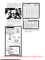
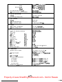
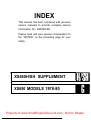
INDEX
XS650E
GENERAL
INFORMATION
PERIODIC INSPECTION
AND ADJUSTMENT
ENGINE OVERHAUL
CARBURETION
CHASSIS
ELECTRICAL
I
APPENDICES
Property of www.SmallEngineDiscount.com - Not for Resale
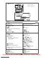
XS650SE SUPPLEMENT
(EPA)
XS650E SUPPLEMENT
*XS650SF USES THIS SUPPLEMENT (EPA)
XS650SE SUPPLEMENT
I
XS650SF/2F SUPPLEMENT
XS650G/SG SUPPLEMENT
Property of www.SmallEngineDiscount.com - Not for Resale
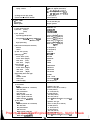
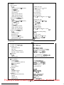
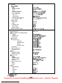
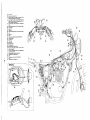
CHAPTER 1.
GENERAL INFORMATION
l-l.
MACHINE IDENTIFICATION . . . . . . . . . . . . . . . a . . . . . . . . . . . . . . . . . . . . . . . . . . .1
l-2.
SPECIAL TOOLS . . . . . . . . . . . . . . . . . . . . . . . . . . . . . . . . . . . . . . . . . . . . . . . . . . . . .
.
Property of www.SmallEngineDiscount.com - Not for Resale
CHAPTER 1.
GENERAL INFORMATION
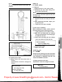
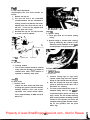
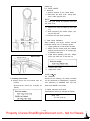
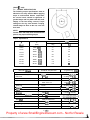
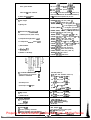
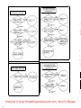
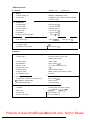
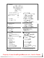
l-l. MACHINE IDENTIFICATION .
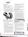
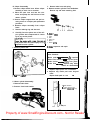
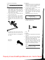
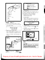
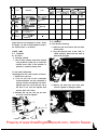
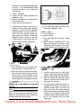
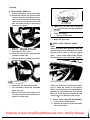
Frame serial number
The frame serial number is stamped on the right side of the steering head stock.
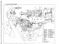
Engine serial number
The engine serial number is stamped on the front of the engine crank case.
NOTE:
The first three digits of these numbers are for model identifications; the remaining digits are the
unit production number.
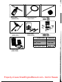
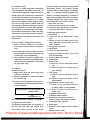
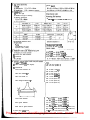
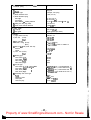
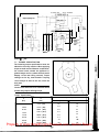
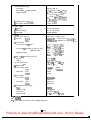
1-2. SPECIAL TOOLS
,
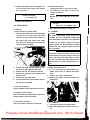
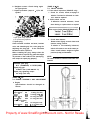
1. Cam chain cutter
Parts No. (90890-01112)
2. Valve spring compressor
(90890-01253)
3. Valve guide reamer
(90890-01211)
5. Piston ring compressors
(90890-01066)
6. Piston support plate
(90890-01067)
J
c
4.
Valve seat cutter set
(90890-01179)
Property of www.SmallEngineDiscount.com - Not for Resale
I
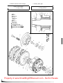
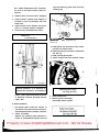
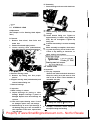
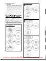
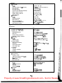
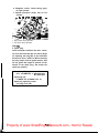
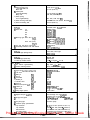
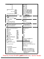
7. Rotor puller
(90890-01070)
10. Drive chain cutter
(90890-01081)
P
8. Clutch holding tool
(90890-01069)
11. Pocket tester
(90890-03096)
9. Slide hammer
(90890~;z)
12. E lectro tester
(9089@0302 1)
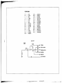
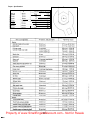
OTHER TOOL
Valve guide remover
Valve guide installer
Spoke wrench
Steering nut wrench
Tappet adjuster wrench
PARTS No.
90890-01200
90890-01201
90890-05087
90890-01051
.256-28137-00
13. Vacuum gauge
(90890-03094)
Property of www.SmallEngineDiscount.com - Not for Resale
-2-
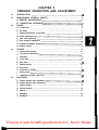
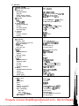
CHAPTER 2.
PERIODIC INSPECTION AND ADJUSTMENT
2-1.
2-2.
2-3.
INTRODUCTION .....................................................
MAINTENANCE INTERVAL CHARTS . . . . . . . . . . . . . . . . . . . . . . . . . . . . . . . . . . . .4
A. PEPIODIC MAINTENANCE ..........................................4
B. LUBRICATION INTERVALS .... ............................... .... 5
ENGINE . . . . . . . . . . . . . . . . . . . . . . . . . . . . . . . . . . . . . . . . . . . . . . . . . . . . . . . . . .. . . . . . 6
A. Carburetor.. . . . . . . . . . . . . . . . . . . . . . . . . . . . . . . . . . . . . . . . . . . . . . . . . . . . . . . . 6
.7
B. Air filten . . . . . . . . . . . . . . . . . . . . . . . . . . . . . . . . . . . . . . . . . . . . . . . . . . . . . . . .
C. Engine/Transmission oil and filter ......................................7
D. Clutch adjustment ..................................................6
E. Cam chain adjustment .............................................. .8
F. Valve clearance adjustment ...........................................8
G. Crankcase ventilation system ..........................................9
H. Exhaust system . . . . . . . . . . . . . . . . . . . . . . . . . . . . . . . . . . . . . . . . . . . . . . . . . . . . 9
2-4.
2-5.
CHASSIS . . . . . . . . . . . . . . . . . . . . . . . . . . . . . . . . . . . . . . . . . . . . . . . . . . . . . . . . . . . . . . 9
A. Fuel petcock cleaning . . . . . . . . . . . . . . . . . . . . . . . . . . . . . . . . . . . . . . . . . . . . . . . .. 9
B. Fuel petcock disassembly .............................................9
C. Fuel hose . . . . . . . . . . . . . . . . . . . . . . . . . . . . . . . . . . . . . . . . . . . . . . . . . . . . . . . . . . . 9
D. Front brake ......................................................10
E. Rear brake . . . . . . . . . . . . . . . . . . . . . . . . . . . . . . . . . . . . . . . . . . . . . . . . . . . . . ..lO
F. Wheels and tires . . . . . . . . . . . . . . . . . . . . . . . . . . . . . . . . . . . . . . . . . . . . . . . . . . . 10
G. Drivechain . . . . . . . . . . . . . . . . . . . . . . . . . . . . . . . . . . . . . . . . . . . . . . . . . . . . . . . 11
H. Front fork oil change .............................................. .12
I. Steering head .....................................................12
J. Lubrication of cables, pivots, etc . . . . . . . . . . . . . . . . . . . . . . . . . . . . . . . . . . . . . .....I3
ELECTRICAL . . . . . . . . . . . . . . . . . . . . . . . . . . . . . . . . . . . . ... . . . . . . . . . . . . . . . . . . 13
A. Contact breaker point adjustment .....................................13
B. Contact breaker point maintenance . . . . . . . . . . . . . . . . . . . . . . . . . . . . . . . . . . . . . 13
C. lgnition timing.............................................................. 14
D. Carbon brushes................................................................ 14
E. Battery.................................................................... 14
F. Sparkplug . . . . . . . . . . . . . . . . . . . . . . . . . . . . . . . . . . . . . . . . . . . . . . . . . . . . . ..... 15
G. Headlight.................................................................. 15
Property of www.SmallEngineDiscount.com - Not for Resale
-3-
CHAPTER 2.
PERIODIC INSPECTION AND ADJUSTMENT
2-1. INTRODUCTION
This chapter includes all information necessary to perform recommended inspection and adjustments, These
preventive maintenance procedures, if followed, will insure more reliable vehicle operation and a longer service
life. The need for costly overhaul work will be greatly reduced. This information applies not only to vehicles
already in service, but also to new vehicles that are being prepared for sale. Any service technician performing
preparation work should be familiar with this entire chapter.
2-2. MAINTENANCE INTERVALS CHARTS
The following charts should be considered strictly as a guide to general maintenance and lubrication intervals.
You must take into consideration that weather, terrain, geographical location, and a variety of individual uses
all tend to alter this time schedule. For example, if the motorcycle is continually operated in an area of high
humidity, then all parts must be lubricated much more frequently than shown on the chart to avoid damage
caused by water to metal parts,
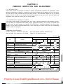
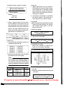
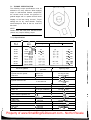
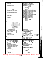
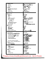
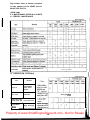
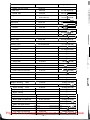
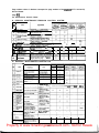
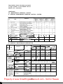
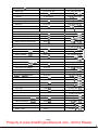
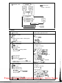
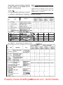
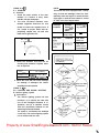
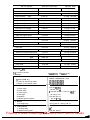
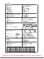
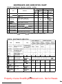
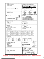
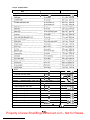
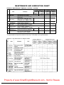
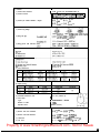
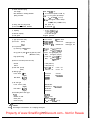
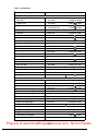
A.PERIODIC MAINTENANCE
Periodic inspection, adjustment and lubrication will keep your motorcycle in the safest
and most efficient condition. Safety is an obligation of the motorcycle owner.
Unit: km (mi
initial
Item
400
800
1,600
3,200
1,600
( 2 5 0 ) (500) ( 1 , 0 0 0 ) (2.000) (1,000)
Remarks
Cylinder
1 Check compression
I
Valves
1 Check/Adjust valve clearance
I
Cam chain
( Check/Adjust chain tension
I
Spark pluqs
I inspect/Clean or replace as required
loI
Air filter
/ Dry type - Clean/Replace as required
Carburetor
| Check operation/Adjust as required
Brake system
Check/Adjust as required - Repair as
(complete)
required
/Adjust free play
!
I
1
I
i
0
Fuel petcocks
Clean/Flush tank as required
0
~1 0
0
breather pipe
Ignition timing
| Adjust/Clean or replace parts as required 1
Lights/Signals
/ Check operation/Replace as required
| Tighten before each trip and/or
Generator brushes | Check brush wear/Replace if necessary
/
io
0
!
0101
I
lo
I
lo
I
~ 0
Top-up/Check specific gravity and
lo
0
I
’
0
I
0
I
1
I
0
I
lo
IO
;
I
10
~
I
0
0
io
I
6,400
I
‘0
i 0
3,200
(2.000) ( 4 , 0 0 0 )
IOI
:
:
Check pressure/Wear/Balance
Fittings/Fasteners
lo I
I
Wheel and tires
Battery
Thereafter every
0
;
0
~
I
I
I
I
0
I
0
I
0
0 1,o i 0
I
o/oj
IO I
0
I
/o/o
lo
lo~o/olo/
1
I
~
I
I
I
lo
Property of www.SmallEngineDiscount.com - Not for Resale
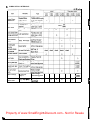
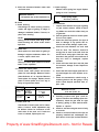
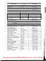
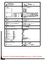
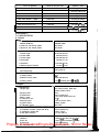
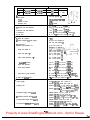
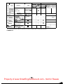
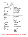
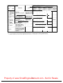
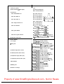
6. LUBRICATION INTERVALS
, a_:._ Y- ,-
mission oil
Drive chain
Control/Meter
Apply thoroughly
Oil filter element
Wheel bearings
Do not over/
Yearly or . . .
Point cam lubrication wicks
Apply
very lightly
12,800
Medium-weight
wheel bearing grease
Light-weight
machine oil
(8.000)
0
0
0
0
Property of www.SmallEngineDiscount.com - Not for Resale
-5
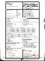
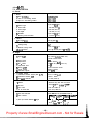
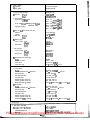
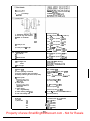
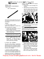
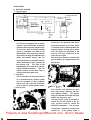
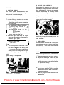
2-3. ENGINE
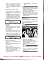
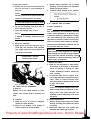
A. Carburetor
1. Idle mixture
The idle mixture is set at the factory by
the use of special equipment. No attempt
should be made to change this adjustment
by the dealer.
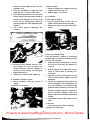
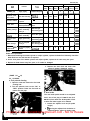
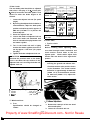
b. Install the attachment and set the vacuum
gauge.
c. Start motorcycle and allow it to warm up
for 2 - 3 minutes. The warm-up is complete when engine responds normally to
throttle opening.
d. Adjust damping valve on each vacuum
gauge until the needle flutters only
slightly. The gauge needles must respond
quickly to rapid opening of the throttle.
e. Both gauge will indicate the same reading
if the carburetors are synchronized.
f. Turn the synchronizing screw until the
gauge readings are the same.
1. Do not adjust
2.
Throttle
Turn the throttle grip to see if it operates
properly and if the play is normal. Make
certain the throttle snaps closed when
released.
1. Synchronizing screw
g.
After adjustment, firmly tighten the plug
screws.
NOTE:
Check gasket. Replace if damaged.
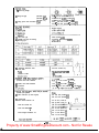
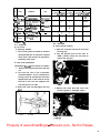
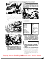
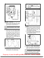
4. Idle speed adjustment.
NOTE:
Carburetors must be synchronized before
setting final idle speed.
1. 5 - 8 mm (0.2 - 0.3 in)
3. Synchronization
NOTE:
Ignition timing and valve clearances must
be set properly before synchronizing
carburetors.
Procedure:
a. Turn fuel petcocks to “PRIME”, and
remove the plug screws for the adapter
attachment holes in the carburetor body.
a. Start the engine and warm it up for a few
minutes.
b. Set the engine idle speed to specified rpm
by turning the throttle stop screw in to
increase the engine speed and back off the
screw to decrease the engine speed.
Use a tachometer for checking and adjusting the engine speed.
I
Standard idle rpm:
1,200 rpm
I
Property of www.SmallEngineDiscount.com - Not for Resale
-6-
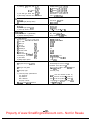
mi.). It should be cleaned more often if
the machine is operated in extremely
dusty areas.
1 .Throttle
nap se-
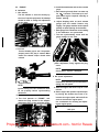
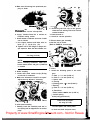
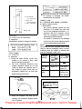
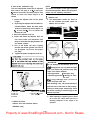
B. Air filters
This model uses a cartridge type air filter
element which consists of foam rubber.
1. Removal
a. Remove the air filter cover by removing
the bolts.
b. Pull out the springs and elements.
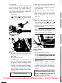
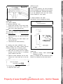
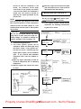
C. Engine/transmission oil and filter
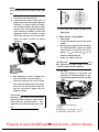
1. Oil level measurement
a. To check the level, warm the engine up
for several minutes. Stop the engine.
With the engine stopped, screw the dip
stick completely out and then rest the
stick in the hole.
1. Oil leuel dip stick
2. Cleaning method
a. Tap the element lightly to remove most of
the dust and dirt; then blow out the remaining dirt with compressed air through
the inner surface of the element. If
element is damaged, replace.
b. Reassemble by reversing the removal procedure. Check whether the element is
seated completely against the case.
c. The air filter element should be cleaned
once a month or every 1,600 km(l,000
NOTE:
When checking engine oil level with the
dip stick, position the machine straight up
and on main stand.
b. The dip stick has a minimum and a maximum mark. The oil level should be
between the two. If the level is low, add
sufficient oil to raise it to the proper level.
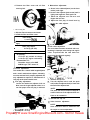
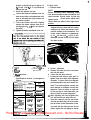
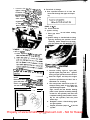
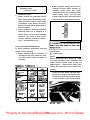
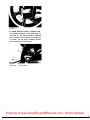
2. Oil replacement and filter cleaning
a. Start the engine. Allow it to warm up for
2-3 minutes. Stop the engine.
b. Place an oil pan under the engine.
c. Remove the drain plugs and drain the oil.
1. drain plugs
Property of www.SmallEngineDiscount.com - Not for Resale
-7
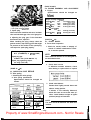
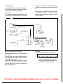
d. Remove the filter cover and oil filter
securing bolt.
HA
2. Mechanism adjustment
a. Screw in the cable adjuster (on the lever
holder) until tight.
b. Screw in the adjuster (push screw) until it
lightly seats against a clutch push rod.
c. Back the adjuster out l/4 turn and
tihgten the lock nut.
d. Adjust the free play of clutch lever by
turning the cable adjuster.
1. Filter securing bolt.
e. Slip the filter element out and clean.
f. Install the filter and filter cover.
Filter torque:
1.0 m-ko f7 f&lb)
/
I
g. Reinstall the drain plugs. (Make sure it is
tight.)
Drain plug torque:
4.4 m-kg (32 ft-lb)
/
h. Add oil through the dip stick hole.
r
I
Oil quantity:
2.0 lit (2.1 qt): periodic oil change
2.5 lit (2.6 qt): engine overhauling
Recommended oil:
Yamalube 4-cycle oil or SAE
20W/40 type “SE” motor oil
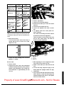
D. Clutch adjustment
This model has a clutch cable length adjuster
and a clutch mechanism adjuster. Normally,
once the mechanism is properly adjusted, the
only adjustment required is maintenance of
free play at the clutch handle lever.
1. Free play adjustment
Loosen the handle lever adjuster lock nut.
Next, turn the length adjuster either in or
out until proper lever free play is achieved.
1, Adjuster
2. Lock nut
c
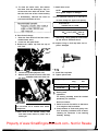
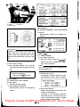
E. Cam chain adjustment
The cam chain becomes stretched with use,
resulting in improper valve timing and engine
noise. To prevent this the cam chain tensioner must be adjusted regularly.
Remove the cap nut.
Turn the adjuster bolt in until the push
rod (inside the adjuster bolt) is flush with
the end of the adjuster bolt.
NOTE:
The push rod will not come out beyond a
certain limit even if the adjuster bolt continues to be screwed in.
Reinstall the cap nut.
Valve clearance adjustment
1 . 2-3mm (0.08-0.12inl
2. Lock nut
NOTE:
Valve clearance must be measured with
the engine at room temperature.
Property of www.SmallEngineDiscount.com - Not for Resale
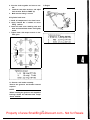
3.
Adjuster
1.
2.
3.
4.
Remove all four tappet covers and the
generator cover.
Turn the crankshaft to align the rotor
mark with the “T” mark on the stator.
This places the pistons at the top dead
center and the valve clearance should be
checked and adjusted at the top dead
center on the compression stroke by
observing when the valve adjusters have
clearance.
Use a feeler gauge to determine the
clearance.
H. Exhaust system
1. Check for leakage from exhaust joints and
retighten joint bolts and nuts.
2. Replace gaskets if necessary.
2-4. CHASSIS
A. Fuel petcock cleaning
1. Turn the petcock lever to the “ON” or
“RES” position. Remove the fuel pipe.
2. Remove the drain cover and clean it with
solvent.
Exhaust valve clearance (cold):
Intake valve clearance (cold):
1 “RES” position
2. Drain cover
5. Loosen the valve adjuster lock nut. Turn
the adjuster in or out to obtain the
correct clearance. Hold the adjuster to
prevent it from moving and throughly
tighten the lock nut.
6. Recheck the clearance after tightening.
G. Crankcase ventilation system
1. Check ventilation hose for cracks or
damage.
2. Replace it if necessary.
B. Fuel petcock disassembly
If the fuel petcock is leaking or excessively
contaminated, it should be removed from the
fuel tank and inspected.
1. Remove fuel tank and position it so that
fuel will not spill when the petcock is
removed.
2. Remove petcock and inspect filter screen.
Clean or replace filter if seriously contaminated.
3. Remove screws on front and rear of petcock and remove plate, gaskets, lever and
diaphragm.
4. Inspect all components and replace any
that are damaged. If the diaphragm is in
any way damaged, or the petcock body
gasket surfaces scratched or corroded, the
petcock assembly must be replaced. If
there is abrasive damage to any component, the fuel tank must be drained and
flushed.
5. Reassemble petcock and install on fuel
tank.
C. Fuel hose
1. Check fuel hose for cracks or damage.
2. Replace it if necessary.
1, Ventilation hose
2. Fuel pipe
Property of www.SmallEngineDiscount.com - Not for Resale
-9-
D. Front brake
The brake can be adjusted by simplay adjusting the distance that the brake lever can
travel. (The piston in the caliper moves forward as the brake pad wears out, automatically adjusting the clearance between the
brake pad and the brake disc.)
1. Adjustment
a. Turn adjuster so that a brake lever end is
5 - 8 mm (0.2 - 0.3 in) before adjuster
contacts master cylinder piston.
Refill with the same type and brand of
brake fluid; mixing fluids may result in a
harmful chemical reaction and lead to
poor performance.
Be careful that water or other contamination does not enter the master cylinder
when refilling. Water will significantly
lower the boiling point and may result in
vapor lock.
E. Rear brake
1. Adjust rear brake pedal play to suit, providing a minimum of 20 - 30 mm (0.8 1.2 in) freeplay. Turn the adjuster on the
rear brake rod in or out until brake pedal
free play is suitable.
NOTE:
Rear brake pedal adjustment must be
checked anytime chain is adjusted or rear
wheel is removed and then reinstalled.
1 . 5-8mmI0.2-0.3inl
2. Lock nut
3. Adjuster
2. Brake pad check
1. Adjuster
1, Indicator cap
To check, open the wear indicator cap
and if any pad is worn to the red line, replace pads.
3. Check the brake fluid level
Insufficient brake fluid may allow air to
enter the brake system, possibly causing
the brake to become ineffective. Check
the brake fluid level and replenish when
necessary and observe these precautions:
a. Use only the designated quality brake
fluid; otherwise, the rubber seals may deteriorate, causing leakage and poor brake
performance.
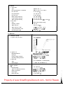
F. Wheels and tires
1. Wheels
a. Check each spoke for tightness.
NOTE:
If loose spokes are found, tighten and
repeat rim runout check.
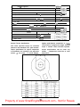
2. Tires
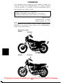
a. Important notice
Proper loading of XS650E is important
for the handling, braking, and other
performance and safety characteristics.
NEVER OVERLOAD THE M O T O R CYCLE.
WARNING: Never overload the motorcycle beyond specified tire limits. Opera-
Recommended brake fluid:
DOT No. 3 Brake fluid
Property of www.SmallEngineDiscount.com - Not for Resale
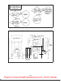
FRONT
REAR
XS650E BASIC
WEIGHT with oil
md full fuel tank
104 kg@29 lb) 119 kg1262 lb)
Standard tire
Bridgestone or Bridgestone or
Yokohama
Yokohama
3.50H19-4PR 4.OOHlB-lPR
Tire load limit
234 kg (515 lb) 280 kg (615 lb]
Cold tire pressure
Normal riding
20 mm (3/4 in)
1.6 kg/cm’
(22 psi)
With passenger 2.0 kg/cm2
or high speed
(28 psi)
riding
With passenger 2.8 kg/cm2
(40 psi)
$$xtra load
Vlinimum tire
:read depth
0.8 mm
(0.03 in)
2.0 kg/cm2
(28 psi)
2.3 kg/cm’
(32 psi)
2.8 kg/cm2
(40 psi)
0.8 mm
(0.03 in)
Make sure the total weight of the motorcycle with
accessories, rider(s) etc., does not exceed the tire
limits.
b. Check the tire wear
If a tire tread shows cross wise lines, it
means that the tire is worn to its limit.
Replace the tire.
c. Check the wheel damage and check the
tightness of spokes.
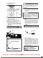
G. Drive chain
1. Tension check
a. Inspect the drive chain with mainstand
erected. Check the tension at the position
shown in the illustration. The normal vertical deflection is approximately 20 mm
(3/4 in).
2. Tension adjustment
a. Loosen the rear brake adjuster.
b. Remove the cotter pin of the rear wheel
axle nut.
c. Loosen the rear wheel axle nut.
d. Loosen the adjuster lock nuts on each
side.
e. To tighten chain turn chain puller adjuster clockwise.
Turn each bolt exactly the same amount
to maintain correct axle alignment.
There are marks on each side of rear arm
and on each chain puller; use them to
check for proper alignment.
1.
2.
3.
4.
5.
Alignment marks
Rear axle nut
Adjuster
Lock nut
Cotter pin
f. After adjusting be sure to tighten the lock
nuts and the rear wheel axle nut.
g. Install a new cotter pin and bend the end
over.
h. In the final step, adjust the play in the
brake pedal and stoplight switch free play.
3. Lubrication
a. First, remove dirt and mud from the chain
with a brush or cloth and then spray the
lubricant between both rows of side plates
and on all center rollers.
Property of www.SmallEngineDiscount.com - Not for Resale
-,I -
b. To clean the entire chain, first remove
the chain from the motorcycle, dip it in
solvent and clean with stiff brush. Then
take the chain out of the solvent and dry
it. Immediately, lubricate the chain to
prevent the formation of rust.
7. Install drain screw.
NOTE:
Check gasket. Replace if damaged.
8. Pour specified amount of oil into the inner tube through the upper end opening.
Front fork oil:
Yamaha fork oil 10 Wt
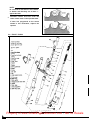
H. Front fork oil change
1. Raise the front wheel off the floor with a
suitable frame stand.
2. Loosen the fork pinch bolts.
3. Remove the rubber cap from the top of
each fork.
I
Front fork oil capacity:
164 - 172 cc (5.54 - 5.82 oz)
each side
After filling, slowly pump the outer tubes
up and down to distribute the oil.
10. Inspect O-ring on fork cap bolts and replace if damaged.
9.
6
1. Pinch bolt
4.
5.
1. O-ring
2. CSP
Loosen the cap bolt (adjuster unit).
Remove drain screw from each outer tube
with open container under each drain hole.
11. Install fork cap bolts.
12. Tighten pinch bolts.
I
1. D
r
e
a
n
iS
c
r
e
w
rCAUTION:
Do not allow oil to contact disc brake
components.
6. After most oil has drained, slowly raise
and lower outer tubes to pump out re
maining oil.
Tightening torque:
m-kg
ft-lb
Fork cap bolt
5.0
36
Pinch bolt
1.0
7
I
I. Steering head
1. adjustment
The steering assembly should be checked
periodically for looseness.
Do this as follows:
a. Raise front end of machine so that there
is no weight on the front wheel.
b. Grasp bottom of forks and gently rock
fork assembly backward and forward,
checking for looseness in the steering
assembly bearings.
Property of www.SmallEngineDiscount.com - Not for Resale
- I2 -
the end of the cable can be held high to
pour in several drops of lubricant. With
throttle grip disassembled, coat the inside
surface of the throttle grip guide tube
with a suitable all-purpose grease to cut
down friction.
2. Meter cables
Pull the inner cable out and apply cable
lube throughly.
c. If there is looseness in the steering head,
loosen the crown pinch bolt, fork pinch
bolts, and steering fitting bolt.
3.
Rear arm pivot shaft
Apply grease to grease nipple on top of
pivot with low pressure hand operated
gun. Apply until fresh grease appears at
both ends of pivot shaft.
Recommended lube:
Medium-weight wheel bearing grease
1. Crown pinch bolt
2. Fork pinch bolt
3. Steering fitting bolt
4.
d. Use steering nut wrench to loosen top
steering fitting nut. The top nut serves as
a lock nut.
e. Tighten the lower steering fitting nut until
the steering head is tight, but does not
bind when forks are turned.
f. Retighten the top steering fitting bolt,
crown pinch bolts and fork pinch bolts, in
that order.
g. Recheck steering adjustment to make sure
there is no binding when the forks are
moved from lock to lock. If necessary,
repeat adjustment procedure.
2. Lubrication
Refer to PAGE 47.
J. Lubrication of cables, pivots, etc.
1. Throttle cable and grip
The throttle twist grip assembly should be
greased at the time that the cable is lubricated since the grip must be removed to
get at the end of the throttle cable. Two
screws clamp the throttle housing to the
handlebar. Once these two are removed,
Brake and change pedal shafts, and center
and side stand pivots Lubricate the shafts
and pivots with Yamaha chain and cable
lube or SAE l0W/30 motor oil.
5. Wheel bearings
Refer to PAGE 39.
2-5. ELECTRICAL
A. Contact breaker point adjustment
1. Remove breaker point cover.
2. Check contact breaker point gap (at
largest gap) with clean feeler gauge.
Contact breaker gap:
0.3 - 0.4 mm (0.012 - 0.016 in)
If necessary, adjust by loosening securing
screws and moving the adjustable contact
point.
3. Tighten adjusting screws and recheck
breaker point gap.
B. Contact breaker point maintenance
1. The contact breaker should be checked
for the following:
a. Wear of the bakelite cam heel
b. Damage of contact point surfaces
Property of www.SmallEngineDiscount.com - Not for Resale
-13-
c. Rust or wear on the breaker arm or arm
shaft.
d. Faulty insulation of the contact braker
assembly.
e Oil or dirt on the assembly.
2. To clean the points, run a point file between the points until the grey deposits
and pits have been removed. Spray the
points with ignition point cleaner or
lacquer thinner, then snap the points shut
on a white business card (or paper of hard
texture) and repeatedly pull the card
through until no more carbon or metal
particles come off on the card. (The card
may be dipped in lacquer thinner or other
cleaner to facilitate this procedure.)
3. Point replacement should be necessary
when the points become severely pitted, if
the heel is broken or worn unevenly, or if
the points become shorted or show faulty
operation.
2.
3.
4.
5.
6.
7.
Ignition timing of right-hand cylinder
must be set first. Connect timing light to
right-hand spark plug lead wire.
Start engine.
The mark stamped on the rotor_ should
line up with the stationary “F” timing
mark. If it does not align, loosen two
breaker backing plate screws and move
the complete backing plate until the mark
on the rotor and the “F” mark align.
Retighten screws. Check timing again for
the right-hand cylinder.
Rev the engine to above 3,500 rpm.
Check whether the mark on the rotor is in
the vicinity of the stationary “full advance” mark.
Repeat procedure (steps 2-6) for another
cylinder.
NOTE:
New points must be cleaned and adjusted.
4.
Add a few drops of light-weight machine
oil onto the felt rubbing pad after each
point adjustment to lubricate the point
cam surface. Do not over oil.
1. Rlghf cylinder timing adfustment
2. Left cylinder timmg adjustment
C. Ignition timing
NOTE:
Point gap must be set before setting timing.
1. Ignition timing is checked with a timing
light by observing the position of the
stationary marks stamped on the stator
and the pointer on the generator.
1. Top dead center
2 . 15’ BT0C11.200 rpm
3. Advanced mark
_
D. Carbon brushes
Visually inspect the carbon brush holder
brushes for obvious breakage or wear.
Standard brush length is 14.5 mm(0.571 in).
Wear limit is 7.0 mm (0.276 in) and
marked there.
E. Battery
A poorly maintained battery will deteriorate
quickly. The battery fluid should be checked
at least once a month.
1. The level should be between the upper
and lower level marks. Use only distilled
water for refilling. Normal tap water contains minerals which are harmful to a
battery; therefore, refill only with distilled water.
2. Always make sure the connections are
correct when installing the battery. The
magnet relay lead is for the (+) terminal
Property of www.SmallEngineDiscount.com - Not for Resale
14 -
and thechassis lead is for the (-) terminal.
Make sure the breather pipe is properly
connected, properly routed, and is not
damaged or obstructed.
NOTE:
The battery must be charged before using
to insure maximum performance. Failure
to properly charge the battery before first
use, or a low electrolyte level, will cause
premature failure of the battery.
Charging current:
Charging hours:
1.4 Amp
10 hrs
F. Spark plug
The spark plug indicates how the engine is
operating. If the engine is operating correctly,
and the machine is being ridden properly, the
tip of the white insulator around the positive
electrode of the spark plug will be a medium
tan color. If the insulator is very dark brown
1. If the insulator is very dark brown or
black color, then a plug with a hotter heat
range might be required. This situation is
quite common during the engine break-in
period.
2. If the insulator tip shows a very light tan
or white color or is actually pure white
and glazed, or if electrodes show signs of
melting, then a spark plug with a colder
heat range is required. Remember, the
insulator area surrounding the positive
electrode of the spark plug must be a
medium tan color. If it is not, check
carburetion, timing and ignition adjustments.
3. The spark plug must be removed and
checked. Check electrode wear, insulator
color, and electrode gap.
Spark plug gap:
0.7 - 0.8 mm (0.028 - 0.031 in)
sent on the surface of the spark plug, and
torque the spark plug properly.
Standard spark plug:
Champion N-7Y or NGK BP 7ES
Tightening torque:
2.0 m-kg (14 ft-lb)
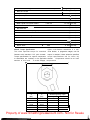
G. Headlight
1. Headlight beam adjustment.
When necessary, adjust the headlight
beam as follows:
a. Adjust horizontally by tightening or
loosening the adjust screw.
To adjust to the right:
Tighten the screw
To adjust to the left:
Loosen the screw
b. Adjust vertically as follows:
1) Loosen adjusting screw and adjust vertically by moving the headlight body.
2) Retighten the screw.
1. Vertical adjustment
2. Horizontal adjustment
2.
Replacing the headlight bulb.
_
_-_._
--
Engine heat and combustion chamber deposits will cause any spark plug to slowly
break down and erode. If the electrodes
a. Loosen bolts and replace bulb.
finally become too worn, or if for any reason
b. After installing, adjust headlight beam.
you believe the spark plug is not functioning
correctly, replace it. When installing the plug,
NOTE:
always clean the gasket surface, use a new
Take care not to damage the headlight. It
gasket, wipe off any grime that might be preis very fragile.
- 15 -
Property of www.SmallEngineDiscount.com - Not for Resale
CHAPTER 3. ENGINE OVERHAUL
3-1.
ENGINE REMOVAL ........................................ ....
A. Preparation for removal ................................... . . . .
.18
. . . .
.18
. . . .
.I8
. . . .
.18
B.
Fuel tank removal . . . . . . . . . . . . . . . . . . . . . . . . . . . . . . . . . . . . . . .
Removal of other parts. ...................................
D. Engine mounting bolts and engine removal ....................
C.
3-2.
ENGINE DISASSEMBLY .................................... ..... .19
. . . . . . . . . . . . . . . . . . . . . 19
A. Governor and breaker assembly removal ........
B. Cylinder head and cylinder removal ............
C. Rocker arm removal ........................
. . . . . . . . . . . . . . . . . . . . . 19
D. Valve removal .............................
E. Piston removal ............................
. . . . . . . . . . . . . . . . . . . . . 19
F. Generator removal .........................
G. Primary drive gear and clutch assembly removal ...
. . . . . . . . . . . . . . . . . . . . . 19
H. Kick axle and change shaft removal ............
I. Electric starter unit removal ..................
. . . . . . . . . . . . . . . . . . . . .20
. . . . . . . . . . . . . . . . . . . . . 19
. . . . . . . . . . . . . . . . . . . . . 19
. . . . . . . . . . . . . . . . . . . . . 19
. . . . . . . . . . . . . . . . . . . . . 20
Oil pump removal. .........................
. . . . . . . . . . . . . . . . . . . . . 20
K. Crankcase disassembly ......................
..................... 20
L. Transmission illustration ....................
. . . . . . . . . . . . . . . . . . . . . 21
M. Shift drum removal ........................
. . . . . . . . . . . . . . . . . . . . . 21
N. Crank shaft removal ........................
. . . . . . . . . . . . . . . . . . . . . 22
J.
3-3.
.18
INSPECTION
AND
REPAIR
. . . . . . . . . . . . . . . . . . . . . . . . . . . . . . . . . . . . . . . . . . .22
A. Cyinder head cover. ............................................... .22
B. Cylinderhead.....................................................22
C. Valve, valve guide and valve seat. ......................................23
D. Valvespring.. . . . . . . . . . . . . . . . . . . . . . . . . . . . . . . . . . . . . . . . . . . . . . . . . . . ..2 4
E. Rocker arm and rocker shaft ........................................ .25
F. Cam shaft wear . . . . . . . . . . . . . . . . . . . . . . . . . . . . . . . . . . . . . . . . . . . . . . . . ..2 5
G. Cam chain, sprocket and dampers .....................................26
H. Cylinder.........................................................2 6
I. Piston and rings .................................................. .26
J.
Pistonpin........................................................27
K. Crankshaft . . . . . . . . . . . . . . . . . . . . . . . . . . . . . . . . . . . . . . . . . . . . . . . . . . . . .
..2 7
p ......................................................
L. Oil pump
..2 7
M. Clutch . . . . . . . . . . . . . . . . . . . . . . . . . . . . . . . . . . . . . . . . . . . . . . . . . . . . . . . .
..2 8
. . . . . . . . . . . . . . . . . . . . . . . . . . . . . . . . . . . . . . . . . . . . . . . . . . . ..2 8
0 . Electric starter gears and clip spring . . . . . . . . . . . . . . . . . . . . . . . . . . . . . . . . . . . .29
P. Kickstarter . . . . . . . . . . . . . . . . . . . . . . . . . . . . . . . . . . . . . . . . . . . . . . . . . . . . ..2 9
N. Transmission
Q. Crankcase and oil passages . . . . . . . . . . . . . . . . . . . . . . . . . . . . . . . . . . . . . . . . . . .29
R. Bearings and oil seals . . . . . . . . . . . . . . . . . . . . . . . . . . . . . . . . . . . . . . . . . . . . . . . 29
Property of www.SmallEngineDiscount.com - Not for Resale
3-4.
ENGINE ASSEMBLY AND ADJUSTMENT . . . . . . . . . . . . . . . . . . . . . . . . . . . .
. .29
A. Shift . . . . . . . . . . . . . . . . . . . . . . . . . . . . . . . . . . . . . . . . . . . . . . . . . . . . . . . . .
. .29
B. Transmission and crankshaft . . . . . . . . . . . . . . . . . . . . . . . . . . . . . . . . . . . . . .
. .29
C. Shifter assembly ................................................ . .30
D. Kick starter assembly ............................................ . .30
E.
Electric-starter gear assembly ...................................... . .30
F.
Clutch . . . . . . . . . . . . . . . . . . . . . . . . . . . . . . . . . . . . . . . . . . . . . . . . . . . . . . .
. -30
G. Generator . . . . . . . . . . . . . . . . . . . . . . . . . . . . . . . . . . . . . . . . . . . . . . . . . . . . .
. .32
. .32
H. Oil pump
p .....................................................
I. Right-hand crankcase cover ....................................... . .32
J. Piston . . . . . . . . . . . . . . . . . . . . . . . . . . . . . . . . . . . . . . . . . . . . . . . . . . . . . . . .
. .32
K. Cylinder and cylinder head. ....................................... . .32
L. Camshaft . . . . . . . . . . . . . . . . . . . . . . . . . . . . . . . . . . . . . . . . . . . . . . . . . . . . .
. .32
M. Cylinder head cover . . . . . . . . . . . . . . . . . . . . . . . . . . . . . . . . . . . . . . . . . . . . .
* -33
N. Governor and breaker assembly . . . . . . . . . . . . . . . . . . . . . . . . . . . . . . . . . . . .
* *33
0. Engine . . . . . . . . . . . . . . . . . . . . . . . . . . . . . . . . . . . . . . . . . . . . . . . . . . . . . . .
. .33
Property of www.SmallEngineDiscount.com - Not for Resale
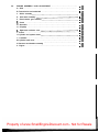
CHAPTER 3.
ENGINE OVERHAUL
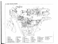
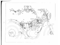
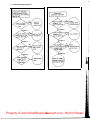
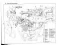
31. ENGINE REMOVAL
A. Preparation for removal
1. All dirt, mud, dust and foreign material
should be thoroughly removed from the
exterior of the engine before removal and
disassembly.
2. Place machine on center stand. Star-f
engine and allow it to warm up. Stop
engine and drain engine/transmission oil.
8. Carburetor (to the left), and throttle cable
9. Brake pedal
10. All wires and cables connecting engine
and chassis
11. Top center engine mounting brackets
(Remove only four bolts for easier reassembly)
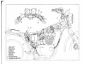
B. Fuel tank removal
1. Turn fuel petcocks to “on” (there is no
“off” position - fuel will not flow from a
petcock on the “on” position unless the
engine is operating). Disconnect fuel pipes
and vacuum pipes from petcock.
2. Lift seat and remove fuel tank holding
bolt. Remove fuel tank.
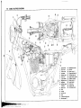
C. Removal of other parts
Remove the following parts in the
1. Exhaust pipes
2. Horn (as a unit)
3. Both side footrests
4. Change pedal and drive chain
5. Left-hand crank case cover
cable.
6. Side covers
7. Air cleaner assembly and
hoses.
T
..--
12. Drive chain (with special tool)
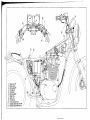
D. Engine mounting bolts and engine removal
1. Remove mounting bolts in the order as
order given.
guide
and clutch
ventilation
2.
Remove the engine to the right.
Property of www.SmallEngineDiscount.com - Not for Resale
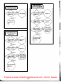
3-2 ENGINE DISASSEMBLY
A. Governor and breaker assembly removal
Remove the following parts in the order
given.
1. Breaker cover
2. Breaker backing plate
3. Breaker housing
4. Governor cover
5. Notched plate
6. Lock nut (using punch and hammer)
7. Governor assembly
C. Rocker arm removal
1. Remove rocker shaft covers.
2. Remove shouldered sleeves and O-rings.
3. Withdraw rocker shafts with the special
tool or 6 mm bolt.
D. Valve removal
1. Compress the valve spring and then remove both retainer locks.
Remove the compressor and lift off the
retainer and springs.
2. Remove valve stem seals.
3. Remove valves.
NOTE:
Deburr any deformed valve stem end. Use
an oil stone to smooth the stem end. This
will help prevent damage to the valve
guide during valve removal.
8. Breaker shaft (to the point side)
9. Dowel pin
10. Advance unit housing
B. Cylinder head and cylinder removal
1. Remove the oil delivery and pipe fitting
attached to the crankcase. Note place
ment of copper gaskets.
2. Remove all tappet covers.
3. Remove spark plugs.
4. Remove four cylinder head cover holding
bolts, three cylinder head holding bolts
and eight cylinder head holding nuts.
5. Remove the head cover. It may be necessary to tap each lightly with a soft
hammer.
6. Remove the camshaft as follows.
a. Remove tensioner adjusting bolt to make
the chain tension loose.
b. Push out the master link pins with the
cam chain cutter.
c. Tie each end of the camchain with a wire
to prevent it from falling into the crankcase.
7. Remove the cylinder head and cylinder.
NOTE:
It is advisable to remove the stator and
rotor after finding the place of the master
link pins. Refer to item “F. Generator
removal.”
E. Piston removal
Remove piston pin clips, piston pins and
pistons.
F.
1.
2.
3.
Generator removal
Remove the stator.
Remove the securing nut and lock washer.
Mount the rotor puller (special tool) onto
the rotor and pull the rotor off.
i .’
~eca9coio7oj
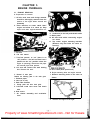
G. Primary drive gear and clutch assembly removal
1. Remove the crankcase cover (right).
2. Loosen the drive gear securing nut by first
placing a rag folded into many layers between the teeth of gears to lock them.
3. Remove six clutch spring screws and pressure plate.
4. Remove clutch plates, friction plates,
push crown, two push rods and two balls.
Property of www.SmallEngineDiscount.com - Not for Resale
-19-
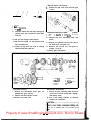
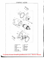
I. Electric starter unit removal
1. Remove the gear train cover, and idle gear
1 and 2.
1.
2.
3.
4.
5.
Push rod
Ball
Push rod (Aluminuml
Push crown
Hold the clutch unit with the holding tool
(special tool), and unscrew the clutch boss
lock nut.
H. Kick axle and change shaft removal
1. Slip the bent sprin
g off and pull the kick
axle assembly out.
2. Remove circlip from left side of change
shaft and pull the shaft out.
1. Kick axle 4. Kick gear 7. Spacer
8. Kickspring
5. Kickclip
2. Holder
9. Spring wide
6. Shim
3. Clip
10. Washer
11. Circlip
2. Remove the four mounting bolts and
motor.
3. Remove the panhead screw (10), gear 2
(6). shaft 2 (5), and gear 1 (4).
4. Remove the circlip (11), and gear assembly (7) (8) (9).
5. Starter gears illustration
D
T
T
2. 1.
3.
4.
5.
6.
g
Y 3
J. Oil pump removal
1. Remove the tachometer drive gear, oil
pump driven gear, and key.
2. Remove the three Phillips screws.
3. Remove the pump unit.
Absorber Idlegear 1
ldlegear 2
Gear 1
Shaft 2
Gear 2
6. 7.
9.
10.
11.
Gear Starter 3 wheel
Gear 4
Panhead screw
Circlip
K.Crankcase disassembly
1. Loosen all case securing bolts and nuts
l/4 turn at a time to avoid case warpage,
and remove them.
2. Use a soft rubber hammer to carefully
separate the crankcases.
Property of www.SmallEngineDiscount.com
- Not for Resale
20 -
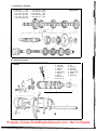
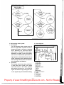
L. Transmission illustration
1.
2.
3.
4.
5.
6.
Main axle
2nd pinion gear
3rd pinion gear
4th pinion gear
5th pinion gear
Drive sprocket
(13T)
(17T)
(20T)
(21T)
(23T)
(17T)
1’
2’
3’
4’
5’
1st wheel gear
2nd wheel gear
3rd wheel gear
4th wheel gear
5th wheel gear
Transmission
(32T)
(27T)
(26T)
(23T)
(22T)
M. Shift drum removal
1.
2.
3.
4.
5.
6.
7.
8.
9.
10.
Bolt
Lock plate
stopper Plate
Shaft bolt
stopper
Stopper spring
Shift cam
Bearing
Shift fork (3)
Shift fork (2)
11.
12.
13.
14.
15.
16.
17.
18.
Shiftfork (1)
Pin
Cotter pin
Guide bar
Cam stopper
Stopper spring
Gasket
Stopper bolt
Property of www.SmallEngineDiscount.com - Not for Resale
1 . Release the stopper spring (6).
4. Remove the neutral detent unit (15-18).
2. Remove the bolts (1) and stopper plate(3). 5. Removecotter pins (13). and pin (12)
6. Pull out the shift cam (7).
3. Pull the guide bar (14) out.
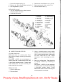
N. Crankshaft removal
1. Tap the crankshaft with a rubber hammer
to loosen it, then lift it out.
2. Crankshaft illustration
1 . Crank 1(L)
14. Cam chain sprocket
2. Crank 2(R)
1 5 . Journal bearing 2
16. Circlip
17. Primary drive gear
3. Crank 2(L)
4 . Crank 2 ( R )
5. Woodruff key
6 . Connecting rod
7. Big end bearing
8. Crank pin washer
9, 10 Crank pin
11. Crankshim
12. Journal bearing 1
18. Plate washer
19. Drive gear
20. Dowel pin
21. Oil seal
22. Spring washer
23. Nut
2 4 . Key
25. Dowel pin
3
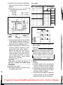
3-3. INSPECTION AND REPAIR
3. Using a rounded scraper, remove carbon
A.Cylinder head cover
Place head cover on a surface plate. There
should be no warpage. Correct by re-surfacing
as follows:
Place #400 or #600 grit wet sandpaper on
surface plate and re-surface head cover using
a figure-eight sanding pattern. Rotate head
cover several times t o avoid removing too
much material from one side.
deposits from combustion chamber. Take
care t o avoid damaging spark plug threads
and valve seats. Do not use a sharp
instrument. Avoid scratching the aluminum.
4. Place on a surface plate. There should be
no warpage. Correct b y re-surfacing as
follows:
Place #400 or #600 grit wet sandpaper
on surface plate and re-surface head using
a figure-eight sanding pattern. Rotate
head several times t o avoid removing too
much material from one side.
B. Cylinder head
1. Remove spark plugs.
2. Remove valves.
22
Property of www.SmallEngineDiscount.com - Not for Resale
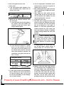
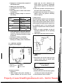
C. Valve, valve guide and valve seat
1. Valve guide
a. If the valve guide inside diameter is beyond serviceable limits, replace with an
oversize valve guide.
Standard
Guide diameter 1 8.010 - 8.019 mm
(I.D.) (IN.EX) / (0.315 - 0.316 in)
b. Measuring the clearance between valve
and valve guide.
1) Insert the valve into the valve guide in
the cylinder head and measure the
clearance in both the X and Y axes,
using a small dial gauge.
d. Use the appropriate shouldered punch
(special tool) to drive the old guide out
and drive the new guide in.
e, After installing the valve guide, use 8 mm
reamer (special tool) to obtain the proper
valve clearance.
f. After fitting the valve guide into the
cylinder head, be sure to grind the valve
seat, and perform valve lapping. The valve
must be replaced with a new one.
2. Grinding the valve seat.
a. The valve seat is subject to severe wear
similar to valve face. Whenever the valve
face is resurfaced, the valve seat should
also be re-surfaced at a 45° angle. In
addition, if a new valve guide has been
installed (without any valve repair), the
valve seat should be checked to guarantee
complete sealing between the valve face
and seat.
CAUTION :
If the valve seat is obviously pitted or
worn, it should be cleaned with a valve
seat cutter. Use the 45° cutter, and
when twisting the cutter, keep an even
downward pressure to prevent chatter
L marks.
1
I
1. Dial gauge
2 . 1 0 m m IO.4 i n )
2) If the measured clearance is greater
than 0.10 mm (0.0039 in) for the
inlet valve or 0.12 mm (0.0047 in) for
the exhaust valve, both the valve and
valve guide should be replaced. The
replacement valve guide should be one
that is oversize.
If cutting section “A” of the valve seat,
use the 8R cutter (radius cutter). If
cutting section “B”, use the 45° cutter.
Valve guide oversize:
Part No.
Size (0.D.)
256-l 1133-l 1 (IN)
256-l 1133-21
15.1 mm (0.594 in)
15.2 mm (0.598 in)
256-l 1134-l 1 (EX)
256-l 1134-21
15.1 mm (0.594 in)
15.2 mm (0.598 in)
c. To ease guide removal and reinstallation,
and to maintain the correct interference
fit, heat the head to 100°C. Use an oven
to avoid any possibility of head warpage
due to uneven heating.
b. Measure valve seat width. Apply mechanic’s bluing dye (such as Dykem) to the
valve face, apply a very small amount of
fie grinding compound around the surface
of the valve seat, insert the valve into
position, and spin the valve quickly back
and forth. Lift the valve, clean off all
grinding compound, and check valve seat
Property of www.SmallEngineDiscount.com - Not for Resale
- 23
width. The valve seat will have removed
the bluing wherever it contacted the valve
face. Measure the seat width with vernier
calipers. It should measure approximately
1.3 mm. Also, the seat should be uniform
in contact area. If valve seat width varies,
or if pits still exist, then continue to cut
with the 45° cutter. Remove just enough
material to achieve a satisfactory seat.
Standard width
I
I
Wear limit
/
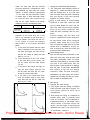
c. If the valve seat is uniform around the
perimeter of the valve face, but is too
wide or not centered on the valve face, it
must be altered. Use either the 8R, 45°
or 25° cutters to correct the improper
seat location in the manner described
below:
1) If the valve face shows that the valve
seat is centered on the valve face, but
too wide, then lightly use both the 8R
and the 25° cutters to reduce the seat
width to 1.3 m m .
2) If the seat shows to be in the middle
of the valve face, but too narrow, use
the 45° cutter until the width equals
1.3 mm.
3) If the seat is too narrow and right up
near the valve margin, then first use
the 8R cutter and then the 45° cutter
to get the correct seat width.
4) If the seat is too narrow and down
near the bottom edge of the valve
face, then first use the 25° cutter and
then the 45° cutter.
I I
’ I
I
3. Lapping the valve/valve seat assembly.
a. The valve/valve seat assembly should be
lapped if (1) neither the seat nor the valve
face are severely worn, or (2) if the valve
face and valve seat have been resurfaced
and now require a final light grinding
operation for perfect sealing.
Apply a small amount of coarse lapping
compound to valve face. Insert the valve
into the head. Rotate the valve until the
valve and valve seat are evenly polished.
Clean off the coarse compound, then
follow the same procedure with fine compound.
Continue lapping until the valve face
shows a complete and smooth surface all
the way around. Clean off the compound
material. Apply bluing dye to the valve
face and rotate the valve face for full seat
contact which is indicated by a shiny surface all around the valve face where the
bluing has been rubbed away.
_. Valve leakage check
After all work has been performed on the
valve and valve seat, and all head parts
have been assembled, check for proper
valve/valve seat sealing by pouring solvent
into each of the intake ports, then the
exhaust ports. There should be no leakage
past the seat. If fluid leaks, disassemble
and continue to lap with fine lapping
compound. Clean all parts thoroughly,
reassemble and check again with solvent.
Repeat this procedure as often as necessary to obtain a satisfactory seal.
D. Valve spring
1. Checking the valve springs
a. This engine uses two springs of different
sizes to prevent valve float or surging. The
chart below shows the basic value
characteristics.
b. Even though the spring is constructed of
durable spring steel, it gradually loses
some of it’s tension. This is evidenced by
a gradual shortening of free length. Use a
vernier caliper to measure spring free
length. If the free length of any spring has
decreased more than 2 mm (0.08 in) from
its specification, replace it.
Property of www.SmallEngineDiscount.com - Not for Resale
24 ~
c. Another symptom of a fatigued spring is
insufficient spring pressure when compressed. This can be checked using a valve
spring compression rate gauge. Test each
spring individually. Place it in the gauge
and compress the spring first to the
specified compressed length with the valve
closed (all spring specifications can be
found in the previous section, valve
spring), then to length with the valve
open. Note the poundage indicated on the
scale at each setting. Use this procedure
with outer springs, then the inner spring.
Standard size:
15.000 ~ 15.018 mm
(0.5906 ~ 0.5913 in)
3. The shaft has been hardened and it should
not wear excessively. If a groove has
developed in this surface that can be felt,
or if it shows a blue discoloration, then
the shaft should be replaced and the
lubrication system (pump and passages)
checked.
Standard shaft diameter:
14.985 ~14.991 mm
(0.5900 ~ 0.5902 in)
NOTE:
All valve springs must be installed with
greater pitch upward as shown.
4. Standard clearance between the rocker
shaft and hole should be 0.009 ~ 0.033
mm (0.00035 ~ 0.00130 in). If measurement shows more than 0.1 mm (0.0004
in) clearance, replace either or both parts
as necessary.
1. Larger patch
2. Smaller pitch
d. Valve spring specifications
Ivalve closed)
Compressed
(1.457 ml
53.5 - 61.5 kg
(1.378 m)
25.5 - 29.0 kg
/
E. Rocker arm and rocker shaft.
1. The rocker arm usually wears at two
locations: (1) at the rocker shaft hole, (2)
at the cam lobe contacting surface.
2. Measure the rocker shaft hole in the
rocker arm.
F. Camshaft wear
1. The cam lobe metal surface may have a
blue discoloration due to excessive friction. The metal surface could also start to
flake off or become pitted. This is due to
poor lubrication, incorrect clearances
(from poor adjustment or valve bounce),
or due to normal wear.
2. If any of the above wear conditions are
readily visible, the camshaft should be replaced. Also, the corresponding rocker
arm contacting surface should be checked
for similar wear and replaced if obvious
wear is noted.
3. Even though the cam lobe surface appears
to be in satisfactory condition, the lobes
should be measured with a micrometer.
Cam lobe wear can occur without scarring
the surface. If this wear exceeds a predetermined amount, valve timing and lift
are affected. Replace the camshaft if wear
exceeds the limits listed below.
Cam Lift (A)
Standard Value
Intake
Exhaust
Wear Llmtt
39.99+0.05 mm 39 84 mm
(1.574+0.002 in1 IO.569 1n1
40 03_+0.05 mm 139.88 mm
11.576+0.002 1n1 i11.570 in)
Width (6)
Standard Value
Wear Llmat
32.24kO.05 mm
‘II 269f0.002 In)
32.09 mm
(1.263 m)
32.30+0.05 mm
11.272+0 002 in1
32.15 mm
(1.266 in)
Property of www.SmallEngineDiscount.com - Not for Resale
- 25
-7
-t-
Q
I
A
B
4. All camshaft bearings should be removed,
cleaned, dried, and the races visually
checked for pits, rust spots or chatter
marks where the balls have dragged, If
any of these conditions exists the bearing(s) should be replaced.
I
Standard
I
Wear Ilmit
I
1 Cylinder
/ outof-round
G.Cam chain, sprocket and dampers
1. Cam chain
Except in cases of oil starvation, the cam
chain wears very little. If the cam chain
has stretched excessively and it is difficult
to keep the proper cam chain tension, the
chain should be replaced.
2. Cam sprockets
Check cam sprockets for obvious wear.
3. Cam chain dampers
Inspect the two vertical (slipper-type)
dampers for excessive wear. Any that
shows excessive wear should be replaced.
Worn dampers may indicate an improperly adjusted or worn-out cam chain,
If the cylinder wall is worn more than
wear limit, it should be rebored.
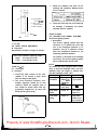
I. Piston and piston rings
1. Piston
a. Measure the outside diameter of the
piston at the piston skirt.
Measurement should be made at a point
10 mm (0.394 in) above the bottom edge
of the piston. Place the micrometer at
right angles to the piston pin.
Standard:
Oversize
Oversize
Oversize
Oversize
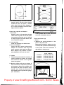
H. Cylinder
1. Inspect the cylinder walls for scratches. If
vertical scratches are evident, the cylinder
wall should be rebored or the cylinder
should be replaced.
2. Measure cylinder wall wear as shown. If
wear is excessive, compression pressure
will decrease. Rebore the cylinder wall
and replace the piston and piston rings.
Cylinder wear should be measured at
three depths with a cylinder bore gauge.
(See illustration.)
1:
2:
3:
4:
74.96, 74.97 mm
(2.951, 2.952 in)
75.25 mm (2.963 in)
75.50 mm (2.972 in)
75.75 mm (2.982 in)
76.00 mm (2.992 in)
Property of www.SmallEngineDiscount.com - Not for Resale
26
b. Determine piston clearance as follows:
J. Piston pin
1. Apply a light film of oil to pin. install in
connecting rod small end. Check for play.
There should be no noticeable vertical
play. If play exists, check connecting rod
small end for wear. Replace pin and connecting rod as required.
2. The piston pin should have no noticeable
free play in piston. If the piston pin is
loose, replace the pin and/or the piston.
Example:
75.02 mm
-74.97 mm
=0.05 mm piston clearance
K. Crankshaft
1. Main bearing and big end bearing visually
inspect all friction surfaces for obvious
pits, scratches, chatter marks, or rust. Replace it if necessary.
2. Small end play(A)
c. Piston ring/ring groove fit must have
correct clearance. If the piston and ring
have already been used, the ring must be
removed and the ring groove cleaned of
carbon. The rings should then be rein
stalled. Use a feeler gauge to measure the
gap between the ring and the land.
Maximum allowable tolerance:
2.0 mm (0.079 in)
;I
3.
Big end side clearance(B)
(0.0016Q.0031 in1 1 0 . 0 0 1 2 - 0 . 0 0 2 8 i n )
Standard clearance:
0.15 - 0.4 mm (0.0059 - 0.016 in)
2. Piston ring
a. The oversize top and middle ring sizes are
stamped on top of the ring.
4. Crankshaft run out(C)
Mount the crankshaft in V-blocks and
check for run out using a dial gauge.
1’
1
Run out limit: 0.05 mm (0.002 in)
b. Push the ring into the bore and check end
gap clearance with a feeler gauge.
NOTE:
The end gap on the expander spacer of
the oil control ring is unmeasureable. If
oil control ring rails show excessive gap,
all three components should be replaced.
Standard
Limit
Topl2nd
ring
0.2 7 0.4 mm
(0.0079 - 0.016 in)
1.0 mm
(0.039 in)
Oil control
(Rails)
Visual
0.2 - 0.9 mm
(0.0079 - 0.0354 in) inspection
L. Oil pump
1. Check the clearance between housing and
outer rotor.
Standard clearance:
0.10 - 0.18 mm (0.0039 - 0.0071 in)
Property of www.SmallEngineDiscount.com - Not for Resale
- 27 -
2. Check the clearance between outer rotor
and inner rotor.
5. Clutch springs
Measure clutch spring free length. Replace
springs as a set if necessary.
Standard clearance:
0.03 - 0.09 mm (0.0012 - 0.0035 in)
M. Clutch
1. Clutch housing
Check dogs on clutch housing. Look for
cracks and signs of galling on edges. If
damage is moderate, deburr. If severe, replace clutch housing.
NOTE:
Galling on the friction plate dogs of the
clutch housing will cause erratic clutch
operation.
2. Clutch boss
Check splines on clutch boss for galling. If
damage is slight to moderate, deburr. If it
is severe, replace clutch boss.
NOTE:
Galling on clutch plate splines will cause
erratic clutch operation.
3. Friction and clutch plates
Check clutch steel plates and friction
plates for heat damage. Measure friction
plate thickness at 3 or 4 points. Measure
clutch plates for warpage. Replace clutch
plate or friction plates as a set if any is
faulty or beyond wear limits.
Clutch spring length:
34.6 mm (1.362 in)
N. Transmission
1. Inspect each shift fork for signs of galling
on gear contact surfaces. Check for bending. Make sure each fork slides freely on
its guide bar.
2. Roll the guide bar across a surface plate.
If bar is bent, replace.
Check
the shift cam grooves for signs of
3.
wear or damage. If any profile has excessive wear and/or damage, replace cam.
4. Check the cam followers on each shift
fork for wear. The follower should fit
snugly into its seat in the shift fork, but
should not be overly tight. Check the ends
that ride in the grooves in the shift cam. If
they are worn or damaged, replace
followers.
5. Check shift cam dowel pins and side plate
for looseness, damage or wear. Replace as
required.
6. Check the shift cam stopper plate and circlip and stopper for wear. Replace as required.
7. Check the transmission shafts using a
centering device and dial gauge. If any
shaft is bent beyond specified limit, replace shaft.
Standard
Wear limit
Friction plate
thickness
3.0 mm
(0.118 inl
2.7 mm
(0.106 in)
I
Clutch plate
-
0.05 mm
8.
warp limit
(0.002 in)
4. Clutch push rod
Check ends of clutch push rod for indentation. If severe, clutch adjustment may
be difficult. Check for looseness of the
steel ends of the push rod. If ends are
loose or indented, replace push rod.
Maximum run-out:
0.03 mm (0.001 in)
I
Carefully inspect each gear. Look for
signs of obvious heat damage (blue discoloration). Check the gear teeth for signs
of pitting, galling or other extreme wear.
Replace as required.
Check to see that each gear moves freely
on its shaft.
10. Check to see that all washers and clips are
properly installed and undamaged. Replace bent or loose clips and bent washers.
9.
Property of www.SmallEngineDiscount.com - Not for Resale
11.
Check to see that each gear properly
engages its counterpart on the shaft.
Check the mating dogs for rounded edges,
cracks, or missing portions. Replace as
required.
0. Electric starter gears and clip spring
1. Check the gears for wear or scratches on
teeth, particularly in the chamfered area
of each gear.
2. The clip spring is fitted to gear (4) (Refer
to PAGE 20) and slides in the groove. A
too-tight or loose-fitting clip may result in
improper operation. If too loose, bend the
clip so that the friction increases, or replace clip.
Friction tension:
2.2 - 2.5 kg (4.9 - 5.5 lb)
P. Kick starter
1. Kick gears
Check the kick gears for wear or scratches
on teeth, particularly in the chamfered
area of each gear.
2. Kick clip spring
The kick clip is fitted to kick gear and
slides in the groove. A too-tight or loosefitting clip may result in improper operation. If too loose, bend the kick clip so
that the friction increases, or replace clip.
3-4. ENGINE ASSEMBLY AND ADJUSTMENT
NOTE:
1) All gaskets and seals should be replaced
when an engine is overhauled. All gasket
surfaces must be cleaned.
2) Properly oil all mating engine and transmission parts during assembly.
All
circlips should be inspected before
3)
Replace distorted circlips.
assembly.
Always replace cotter pins and piston pin
clips after one use.
A. Shift
(Refer to PAGE 21)
Install shift forks, shift cam, guide pin, cotter
pin, guide bar, stoper plate and detent. Apply
LOCK-TITE to eccentric bolt.
NOTE:
Check for smooth and complete shifting after
installing transmission.
Friction tension:
1.2 - 1.7 kg (2.0 - 3.7 lb)
B. Transmission and crankshaft
Q. Crankcases and oil passages
1. Check crankcases for cracks or other
damage.
2. Clean all oil passages and blow out with
compressed air.
1.
2.
Rotate shift cam to neutral position.
Install the transmission, bearings and seals
onto the upper case.
3. Install crankshaft, seal and bearings.
NOTE:
Fit each bearing over each locating pin
and push the crankshaft into position by
hand. Each bearing has line or punch
mark which indicates the position of
mating surface.
R. Bearings and oil seals
1. After cleaning and lubricating bearings,
rotate inner race with a finger. If rough
spots are felt, replace the bearing.
2. Check oil seal lips for damage and wear.
Replace as required.
Property of www.SmallEngineDiscount.com
- Not for Resale
29 -
4. Make sure all bearings are positioned properly as shown.
1. Kick clap
1. No clearance
5. Fit the chain over the cam sprocket,
6. Apply Yamaha Bond No. 4 sealant to
crankcase mating surface.
7. Install bottom crankcase and nuts. Install
nuts as follows:
a. Use copper washers and blind nuts on
bolts (1). (2), (3), (4), (12), (13).
b. Tighten nuts in two stages in proper torque sequence. Start with bolt number one.
2. Positioning the kick clip in the groove,
rotate the kick axle by kick lever l/2 turn
counterclockwise.
3. Push the axle in.
4. Check for correct operation.
E. Electric-starter gear assembly
Install the unit as shown.
(Refer to PAGE 20, if necessary.)
Crankcase torque:
2.2 m-kg (16 ft-lb)
NOTE:
Before installing crankcase, make sure
electric starter shaft 2 and gear 1 (PAGE 20)
is installed.
C. Shifter assembly
1. Install shift shaft. Install circlip (E-clip)
on left side of crankcases.
2. Make sure distances A and B are equal.
Adjust them by adjuster if necessary.
1. Adjuster
!
‘*-)]I
1. Clip
F. Clutch
1. Install the following parts in the order
given.
2 . A=B
D. Kick starter assembly
1. Partially insert the assembly until the return spring can be slipped over its anchor
point.
a. Plate 1, t = 1 mm (0.039 in)
b. Plate 2, t = 2 mm (0.079 in)
c. Spacer shaft
d. Housing
e. Bearing plate, t = 1 mm (0.039 in)
f. Bearing
g. Plate 2, t = 2 mm (0.079 in)
h. Clutch boss
i. Plane washer, t = 2.6 mm (0.102 in)
j. Conical spring
k. Nut (using special tool)
Clutch lock nut torque:
6.5 m-kg (47 ft-lb)
I. Friction plates and clutch plates
m. Push rods, balls and push crown
Property of www.SmallEngineDiscount.com - Not for Resale
- 30 -
n. Pressure plate and clutch springs
/
o. Primary drive gear
I
Clutch screw torque:
1 .O m-kg (7 ft-lb)
a. Plate 1
b. Plate 2
C. Spacer shaft
d. Housing
e. Bearing plate
f. Bearing
g. Plate 2
h. Clutch boss
i. Plane washer
j. Conical spring
k. Nut (usmg special tool)
I. Friction plates and clutch plates
m. Push rods, balls and push crw,”
n. Pressure plate and clutch spring
Drive gear torque:
9 m-kg (65 ft-lb)
k
a = 1 .o mm
b =2.0
e = 1.0
f = 2.0
g =2.0
I = 2.6
i = 2.0
m
d
-
Property of www.SmallEngineDiscount.com - Not for Resale
G. Generator
1. Lock the crank rotation at the primary
drive gear.
2. Reverse the generator removal sequence.
2. Install pistons on rods. The arrow on the
pistons must point to the front of the
engine.
NOTE:
Always install new piston pin clips.
H. Oil pump
Reverse the oil pump removal sequence.
K. Cylinder and cylinder head
Install the tensioner cushion onto crankcase.
2. Install a new cylinder base gasket.
3. Install cylinder using special tool.
4. Install the cylinder head gasket and
cylinder head.
1.
I. Right-hand crankcase cover
While properly engaging oil pump gear, install
new case cover gasket and right-hand crankcase cover. Tighten holding screws gradually
until proper torque is reached.
Crankcase cover holding screw torque:
1.0 m-kg (7 ft-lb)
NOTE:
The assembly of the cylinder head is the
reverse of the disassembly procedure.
Install valve springs with tighter windings
(smaller pitch) down,
L. Camshaft
1. Rotate the piston to TDC.
2. Install the, chain onto the camshaft with
no slack in the cam chain on the front
portion (opposite side from the tensioner).
J. Piston
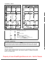
1, Position piston rings as shown.
NOTE:
1) Make sure ends of oil ring expanders
are not overlapped.
2) Manufacturer’s marks or numbers
stamped on the rings are on the top
side of the rings. Coat pistons and rings
well with oil.
1. Center
2. No clearance
3. Position the groove in the left side of the
cam sprocket so that it lines up with the
sprocket centers.
ii!
1.
2.
3.
4.
5.
‘1.
TO P
2nd
Expander
spacer upper
spacer lower
Property of www.SmallEngineDiscount.com - Not for Resale
- 32 -
t
4. Joint the chain together and revet a new
link.
5. Install the cam chain tensioner, and adjust
6.
O. Engine
chain tension. Refer to PAGE. (8).
Make sure the timing is correct.
M. Cylinder heed cover
1. Install all components in the head cover.
2. Apply Yamaha No. 4 sealant to cover
mating surfaces.
3. Install all head cover retaining nuts and
bolts and thread them down until lightly
seated.
4. Tighten them with torque wrench in the
order given
11
1. 4 5 (M10).5.0 m-kg (36 ft-lb)
N. Governor and breaker assembly
Reverse the governor and breaker removal
sequence.
NOTE:
Before inserting the governor rod, supportive
bearings should be lubricated with molybdenum disulfide.
Property of www.SmallEngineDiscount.com - Not for Resale
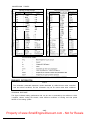
CHAPTER 4. CARBURETION
4-1.
CARBURETOR.. . . . . . . . . . . . . . . . . . . . . . . . . . . . . . . . . . . . . . . . . . . . . . . . . . .
..3 6
A. Description.......................................................3 6
B. Specifications.....................................................3
6
C. Disassembly.......................................................3
6
D. lnspecition.. . . . . . . . . . . . . . . . . . . . . . . . . . . . . . . . . . . . . . . . . . . . . . . . . . . .
..3 6
E. Adjustments ......................................................37
Property of www.SmallEngineDiscount.com - Not for Resale
41. CARBURETOR
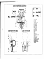
A. Description
Air flow through the venturi is controlled by
a throttle slide (vacuum piston). The slide is
raised and lowered by engine vacuum rather
than a cable linked directly to the throttle
grip.
B. Specifications
Main jet
Jet needle
Needle jet
Starter jet
Fuel valve seat
Pilot jet
Fuel level
#135
502-3
z-2
To inspect starter jet, remove three (3)
screws holding the starter body to the right
side of the carburetor.
6. Remove the four screws holding the float
bowl cover. Remove float bowl cover. The
main jet is located under a cover in the
float bowl.
7. Pull out float pivot pin. Remove the float
assembly. Be careful not to lose the float
valve needle located under the float level
adjustment tongue. Remove the needle
jet.
8. Reassemble in reverse order. Pay close
attention to the installation of the
vacuum piston diaphragm.
5.
#a0
2mm
#27.5
24*1 mm(0.94+0.04 in)
(above gasket surface)
NOTE:
The low speed mixture screw settings are
adjusted at the factory with the use of specialized equipment. Do not attempt to change
these settings.
C. Disassembly
1. Prepare to separate carburetors (separation not necessary if only float level
adjustment or throttle value inspection is
to be done). Remove starter lever. Loosen
starter lever securing screws and remove
starter lever rod.
2. Remove upper and lower brackets. Note
position of synchronizing screws for
guidance in reassembly. Separate carburetors.
3. Remove vacuum chamber cover. Remove
the spring, needle fitting clip, needle,
and diaphragm (piston valve).
4. Note that there is tab on the rubber
diaphragm. There are matching recesses
in the carburetor body for the diaphragm
tab.
D. Inspection
1. Examine carburetor body and fuel passages. If contaminated, wash carburetor in
petroleum-based solvent. Do not use
caustic carburetor cleaning solutions.
Blow out all passages and jets with compressed air.
2. Examine condition of floats. If floats are
leaking or damaged, they should be replaced.
3. Inspect inlet needle valve and seat for
wear or contamination. Replace these
components as a set.
4. Inspect piston valve and rubber diaphragm. If the piston is scratched or the
diaphragm is torn, the assembly must be
replaced.
- 36 -
Property of www.SmallEngineDiscount.com - Not for Resale
E. Adjustments
1. Float level adjustment
Measure the distance from the bottom of
the float to the float bowl gasket surface.
Bend the tongue on the float arm if any
float level adjustment is necessary. Both
floats must be at the same height. If the
fuel level is too high, a rich air/fuel mixture will occur. If too low, a lean mixture
will result.
I
1. Tongue
A . 24+1 m m (0.94f0.04 in1
- 3 7
-
Property of www.SmallEngineDiscount.com - Not for Resale
CHAPTER 5. CHASSIS
5-1.
FRONT WHEEL ...................
. . .
. . . .
................... . .39
A. Removal .......................
. . .
. . . .
..................... 39
B.
Front axle inspection . . . . . . . . . . . . .
. . .
. . . .
..................... 39
C.
Front wheel inspection. ...........
. . .
. . . .
..................... 39
D. Replacing wheel bearings ..........
. . .
. . . .
..................... 39
Installing front wheel .............
. * .
. . . .
..................... 39
E.
5-2.
..................... 40
. . . . * .40
A. Removal . . . . . . . . . . . . . . . . . . . . . . . . . . . . . . . . . . . . . . . . . . . . . . .
. . . . . .40
B. Rear axle inspection ......................................
. . . . . .40
C. Replacing wheel bearings ..................................
. . . . . -40
D. Rear wheel inspection ....................................
. . . . . .40
E. Installing rear wheel ......................................
REAR WHEEL ....................
. . .
. . . .
F. Rear wheel illustration ....................................
5-3.
. .
. . . .40
..4 0
BRAKES . . . . . . . . . . . . . . . . . . . . . . . . . . . . . . . . . . . . . . . . . . . . . . . . . . . . . . . . .
A. Caliper pad replacement .............................................40
.42
B. Caliper disassembly. . . . . . . . . . . . . . . . . . . . . . . . . . . . . . . . . . . . . . . . . . . . . . . .
C. Master cylinder disassembly ..........................................42
D. Brake inspection and repair ..........................................42
E. Brake reassembly ..................................................43
5-4.
WHEELS, TIRES, TUBES ......................................... .. .44
A. Wheel inspection ..................................................44
.44
B. Tire, tube removal . . . . . . . . . . . . . . . . . . . . . . . . . . . . . . . . . . . . . . . . . . . . . . . .
C. Installation .......................................................44
5-5.
5-6.
REAR WHEEL SPROCKET ............................................44
..4 5
FRONT FORKS . . . . . . . . . . . . . . . . . . . . . . . . . . . . . . . . . . . . . . . . . . . . . . . . . . .
A. Removal and disassembly ............................................46
..4 6
6. Inspection . . . . . . . . . . . . . . . . . . . . . . . . . . . . . . . . . . . . . . . . . . . . . . . . . . . . .
5-7.
..4 6
C. Assembly . . . . . . . . . . . . . . . . . . . . . . . . . . . . . . . . . . . . . . . . . . . . . . . . . . . . . .
STEERING HEAD . . . . . . . . . . . . . . . . . . . . . . . . . . . . . . . . . . . . . . . . . ..~.......4 7
A. Adjustment . . . . . . . . . . . . . . . . . . . . . . . . . . . . . . . . . . . . . . . . . . . . . . . . . . . .
..4 7
B. Removal.........................................................4 7
..4 7
C. Inspection . . . . . . . . . . . . . . . . . . . . . . . . . . . . . . . . . . . . . . . . . . . . . . . . . . . . .
5-8.
D. Reassembly . . . . . . . . . . . . . . . . . . . . . . . . . . . . . . . . . . . . . . . . . . . . . . . . . . . . ..4 7
SWING ARM........................................................4
7
..4
7
A. Inspection . . . . . . . . . . . . . . . . . . . . . . . . . . . . . . . . . . . . . . . . . . . . . . . . . . . . .
B. Swing arm removal .................................................4.8
C. Swing arm lubrication ..............................................48
5-9.
REAR SHOCK ABSORBER ............................................48
A. Removal . . . . . . . . . . . . . . . . . . . . . . . . . . . . . . . . . . . . . . . . . . . . . . . . . . . . . . . . . .
.
B. Inspection . . . . . . . . . . . . . . . . . . . . . . . . . . . . . . . . . . . . . . . . . . . . . . . . . . . . . . .
5-10.
CABLES AND FITTINGS .............................................48
...48
A. Cablemaintenance . . . . . . . . . . . . . . . . . . . . . . . . . . . . . . . . . . . . . . . . . . . . . .
B. Throttle maintenance ...............................................48
- 38 -
Property of www.SmallEngineDiscount.com - Not for Resale
CHAPTER 5.
CHASSIS
5-l. FRONT WHEEL
A. Removal
1. Remove cotter pin from front axle nut.
2. Remove the front axle nut.
3. Loosen the two axle holder nuts at
the bottom of the fork leg.
4. Raise the front wheel of the machine by
placing suitable stand under the engine.
5. Remove the front wheel axle by simultaneously twisting and pulling out on the
axle. Then remove the wheel assembly.
The speedometer gear unit housing must
be removed.
a) If the run out is up and down, loosen
spokes opposite the high spot and tighten
the spokes at the high spot.
b) If the run out is sideways, loosen the
spokes at the high spot, and tighten
the spokes opposite the high spot.
D. Replacing wheel bearings
If the bearings allow play in the wheel hub or
if wheel does not turn smoothly, replace the
bearings as follows:
1. Clean the outside of the wheel hub.
2. Drive the bearing out by pushing the
spacer aside and tapping around the
perimeter of the bearing inner race with a
soft metal drift pin and hammer. The
spacer “floats” between the bearings. Both
bearings can be removed in this manner.
3. To install the wheel bearing, reverse the
above sequence. Be sure to grease the
bearing before installation. Use a socket
that matches the outside race of the bearing as a tool to drive in the bearing.
B. Front axle inspection
Remove any corrosion from axle with emery
cloth. Place the axle on a surface plate and
check for bends. If bent, replace axle.
C. Front wheel inspection
1. A rim can develop warpage. It is due to
(1) running the wheel into an object and
bending the outer rim, or (2) one or more
spokes loosening.
2. Check for warpage by mounting the wheel
on a stand (or, if the wheel is attached to
a motorcycle, it can be blocked up and
held in place). Use some device to measure
or detect movement then slowly spin the
wheel and note the amount of rim “runout”. It should not exceed 2 mm(0.08 in).
3. If all the spokes are tight, and the rim
shows no obvious signs of damage, and
yet run out is still excessive, do the following:
E. Installing front wheel
When installing front wheel, reverse the removal procedure. Note the following points:
1. Lightly grease lips of front wheel oil seals
and gear teeth of speedometer drive and
driven gears. Use lightweight lithium soap
base grease.
2. Make sure there is enough gap between
disc pads.
3. Check for proper engagement of the boss
on the outer fork tube with the locating
slot on speedometer gear unit housing.
4. Always secure the front wheel axle as
follows:
a Tighten the front axle nut.
Axle nut torque:
8.5 m-kg (61 ft-lb)
J
Property of www.SmallEngineDiscount.com - Not for Resale
,
b. Tighten axle holder nuts. First tighten nut
on front end of axle holder, then tighten
nut on rear end.
Holder nut torque:
1 .O m-kg (7 ft-lb)
E. Installing rear wheel
1. Lightly grease lips of rear wheel oil seals.
2. To install the rear wheel, reverse the
removal procedure.
NOTE:
Always use a new cotter pin on the axle
nut.
c. install a new cotter pin.
Torque:
Axle nut: 15 m-kg(l08 ft-lb)
5-2. REAR WHEEL
F. Rear Wheel lubrication (on page 41)
A. Removal
1. Place machine on center stand.
2. Disconnect the tension bar, and the brake
rod from the rear shoe plate. Pay strict
attention to the presence and location of
the tension bar lock washer and cotter
key. These are safety parts and must be
included during assembly.
5-3. BRAKES
CAUTION:
Disc brake components rarely require disassembly. Do not disassembly components
unless absolutely necessary. If any hydraulic
connection in the system is opened, the entire
system should be disassembled, drained,
cleaned and then properly filled and bled
upon reassembly.
CAUTION:
D O not use solvents on brake internal components. Solvents will cause seals to swell and
distort. Use only clean brake fluid for cleaning. Use care with brake fluid. Brake fluid is
injurious to eyes and will damage painted surfaces.
L
2.
Loosen the chain tension adjusting nuts
and bolts on both right and left sides.
3. Remove the rear axle cotter pin and nut.
4. Remove the right-hand chain adjuster and
distance collar.
5. Remove the rear brake plate.
6. Lean the machine to the left and remove
the rear wheel assembly.
A.Caliper pad replacement
1. It is not necessary to disassemble the
brake fluid hoses to replace the brake
pads.
2. Remove the caliper suppdrt bolt.*
3. Remove the phillips screw that holds the
brake pads.
B. Rear axle inspection
(See front Wheel, Axle Inspection Procedure.)
C. Replacing wheel bearings
Rear wheel bearing replacement is similar to
the procedure for the front wheel.
D. Rear wheel inspection
(See Front Wheel, Inspection Procedures.)
1. Caliper wppcm bolt
2. Pad screw
4. Pull caliper cylinder off caliper frame.
5. Install new brake pads. Replace pads as a
set.
Property of www.SmallEngineDiscount.com - Not for Resale
-40 -
Property of www.SmallEngineDiscount.com - Not for Resale
B. Caliper disassembly
1. Remove caliper brake hose. Allow caliper
assembly to drain into a container.
2. Place the open hose end into the container and pump the old fluid out of the
master cylinder.
3. Remove caliper support bolt and pad securing screw as in Caliper pad replacement
procedure.
4. Remove caliper assembly from caliper
frame.
5. Remove retaining ring and dust seal.
6. Carefully force the piston out of the caliper cylinder with compressed air. Never
try to pry out the piston.
that piston does not cause injury as it is
expelled from the cylinder.
7. Remove piston seal.
3. Remove brake lever and spring.
4. Remove master cylinder from handlebars.
Remove cap and drain remaining fluid.
& h%;&
1 & &
1. Snap
2.
3.
4.
5.
6.
7.
ring
Cylinder CUP IFI)
Piston
Shim
Piston cup
Spacer
Return spring
D.Brake inspection and repair
Recommended Brake Component Replacement Schedule:
Brake pads . . . . . . . . . . . . . . . .As required
Piston seal, dust seal . . . . . Every two years
Brake hoses . . . . . . . . . .Every four years
Brake fluid . . . . . . . . . . Replace only when
brakes are disassembled
Pad s c r e w 3. sntm
4. Pads.
2. Shim
1. Replace caliper piston if it is scratched.
2. Replace any brake pad worn beyond
limits.
Replace brake pads as a set.
_
A
C. Master cylinder disassembly
1. Remove brake hose.
2. Remove front brake switch.
A : Pad thickness
6. : Wear limit (1.5 mm)
C : Wear indicator(red line)
C
?
Pad
l_
\
Back plate
Property of www.SmallEngineDiscount.com - Not for Resale
cap, boot bushing, piston seal, dust seal,
retaining ring.
See “Caliper Replacement Pad” procedure
for parts to be replaced when pads are
replaced.
3.
Replace piston and dust seals if damaged.
4.
Inspect master cylinder body. Replace if
scratched. Clean all passages with new
brake fluid.
Inspect brake hoses. Replace every four
years or if cracked, frayed or damaged.
Check for wear and deflection of disc.
5.
6.
Wear limit:
1.5 mm (0.06 in)
_
I
Bleed screw
1.
(with
2. Bush boot
3. Piston seal
cap)
4. Dust seal
5. Retaining ring
a. Install piston seal and piston. Place caliper
cylinder into caliper frame.
b. Install pad spring and retainer. Install dust
seal and clip.
c. Install pad spring and pads.
d. Install support bolt and remount caliper
on brackets.
1. Dial gauge
a
1. Mounting bolt
Maximum deflection: 0.15 mm(0.006 in)
Minimum disc thickness: 6.5 mm(0.26 in)
If disc is worn beyond minimum thickness
or deflection exceeds specified amount,
replace disc.
Mounting bolt torque:
3.5 m-kg (25 ft-lb)
3.
4.
Attach brake hoses.
Master cylinder reassembly
Reassemble master cylinder.
E. Brake reassembly
All internal parts should be cleaned in
new brake fluid. Internal parts should be
lubricated with brake fluid when installed.
2. Caliper reassembly
Replace the following parts whenever a
caliper is disassembled: bleed screw and
Property of www.SmallEngineDiscount.com - Not for Resale
Use two wide, flat tire irons with rounded
edges to work the tire bead over the edge
of the rim, starting 180” opposite the
tube stem. Be careful not to pinch the
tube as you do this.
4. After you have worked on side of the tire
completely off the rim, slip the tube out.
[I
Be very careful not to damage the stem
while pushing it back out of the rim hole.
5. Brake disc assembly
If brake disc has been removed from hub
or is loose, tighten bolts. Use new locking
washers and bend over locking tabs after
bolts are tightened.
6. Air bleeding
-CAUTION:
If the brake system is disassembled or if
any brake hose has been loosened or removed, the brake system must be bled to
remove air from the brake fluid. If the
brake fluid level is very low or brake
operation is incorrect, bleed the brake
system.
a. Add proper brake fluid to the reservoir.
Install the diaphragm, being careful not
to spill or overflow the reservoir.
b. Connect the clear plastic tube tightly to
the caliper bleed screw. Put the end of the
tube into a container.
C. Slowly apply the brake lever several times.
Pull in lever. Hold lever in “on” position.
Loosen bleed screw. Allow the lever to
travel slowly toward its limit. When the
limit is reached, tighten bleed screw.
Continue
step C until all air bubbles are
d.
removed from system.
NOTE:
If bleeding is difficult, it may be necessary
to let the brake system stabilize for a few
hours. Repeat bleeding procedure.
3.
NOTE: __
If you are changing the tire itself, then
finish the removal by working the second
bead off the rim.
C. Installation
Reinstall the tire and tube by reversing the
disassembly procedure. After the tube has
been installed, but before the tire has been
completely slipped onto the rim, put a small
amount of air into the tube. This removes any
creases that might exist. Release the air and
continue with reassembly. After the tire has
been completely slipped onto the rim, make
sure the stem comes out of the hole in the rim
at a right angle to the rim. Finally inflate the
tire. Refer to PAGE (10).
Front Tire
INormal riding
Rear Tire
1.6 kg/cm* (22 psi) 2.0kg/cm2 (29psij
NOTE:
Make sure the wheel is balanced every time
the tire is replaced. (Refer to “Front wheel
inspection”.)
5-5. REAR WHEEL SPROCKET
5-4. WHEELS, TIRES, TUBES
A. Wheel inspection
Wheels should be inspected frequently. Wheel
run-out is discussed in Chapter 5-1.
B. Tire, tube removal
1. Remove valve cap, valve core and valve
stem lock nut.
2. When all air is out of tube, separate tire
bead from rim (both sides) by stepping on
tire with your foot.
1. Bend the lock washer ears flat.
2. Remove the sprocket mounting bolts.
Check the lock washer and bolt for
damage. If the lock washer is not bent
over the hexagon bolt head, or is broken,
or the bolt is loose, the sprocket can come
loose.
Property of www.SmallEngineDiscount.com - Not for Resale
NOTE:
Be sure that all lock tabs are not cracked
or broken and that they are all bent U P
against the bolts.
3
Wear limit 3 mm (0.02 in)
Constant friction and force from the
chain creates wear on the sprocket teeth.
If wear has progressed to the extent
shown in this illustration, replace the
sprocket.
Slip off
5-6. FRONT FORKS
I
--_w--J’
/
26. Nut
u
i‘
0
/I
/
I
31
I
30
:
d
2
126
it
I
7
t
-
2
7
I’
I
_ _ - J
Property of www.SmallEngineDiscount.com - Not for Resale
-45 -
A. Removal and disassembly
NOTE:
For fork oil replacement only, refer to PAGE
(12)
1.
Disconnect speedometer cable. Disconnect
brake calipers and remove front wheel.
Place wooden wedge or other object into
caliper assemblies to keep brake pads
apart. Remove front fender.
2. Loosen pinch bolts on steering stem and
crown and remove fork.
Remove
fork tube caps, spring stopper
3.
seats, and oil drain screws. Drain fork oil.
4.
Remove Allen bolt from bottom of fork
assembly. Pull inner tube out of outer
tube.
B. inspection
1. Examine fork inner tube for scratches and
straightness. If the tube is scratched severely or bent, it should be replaced.
2. If the lips of the oil seal are worn, or the
oil seal is leaking, replace it.
3. Check the outer tube for dents. If any
dent causes the inner tube to “hang up”
during operation, the outer tube should
be replaced.
4. Check the free length of the springs.
Spring free length:
482 mm (18.98 in)
5.
Check the O-ring on the top spring seat. If
damaged, replace O-ring.
6
5. To remove fork seal, pull off dust cover.
Remove spring clip over oil seal. Pry out
oil seal, being careful to not damage the
fork tube.
1. O-ring
C. Assembly
1. Make sure all components are clean before
assembly.
2. Apply oil to the fork seal and install the
seal spacer and seal by pressing in with a
large socket. Install retaining clip.
3. Install inner tube into outer tube. Install
dust cover. Install and tighten Allen bolt
and washer. Assembly procedure is the
reverse of the disassembly procedure.
NOTE:
When installing fork springs, the greater
pitch should be at the bottom.
Property of www.SmallEngineDiscount.com - Not for Resale
D. Reassembly
1. Grease bearings and races with wheel bearing grease.
1. Bottom
2. TO P
5-7. STEERING HEAD
A.Adjustment
(See Chapter 2-4 for Steering Head Adjustment.)
Install steering stem (underbracket) and
bearings.
Install bottom fitting nut. Tighten to
approximately 2.0 - 2.6 m-kg (14 - 19
ft-lb). Do not over-tighten. Tighten top
fitting nut.
Continue reassembly in reverse assembly
order.
When assembly is complete, check steering stem by turning it from lock to lock.
If threr is any binding or looseness, readjust steering stem tightness.
B. Removal
1. Remove front wheel, front forks and
handle bars.
2. Remove front brake pipe junction.
3. Loosen steering stem (underbracket)
pinch bolt. Remove stem bolt and washer.
Under bracket.
1. Crown Dlnch bolt
3. Steering fitting bolt
2. Fork pinch bolt
4. Remove steering crown.
5. Remove top fitting nut. Use proper
spanner.
6. Support steering stem (underbracket) and
remove bottom fitting nut.
7. Remove bearings.
C. Inspection
1. Wash bearings in solvent.
2. inspect bearings for pitting or other
damage. Replace bearings if pitted or
damaged. Replace races when bearings are
replaced.
3. Clean and inspect bearing races. If races
are damaged, replace races and bearings.
4. Install bearings in races. Spin bearings. If
the bearings hang up or are not smooth in
their operation in the races, replace bearings and races.
5-8. SWING ARM
A. Inspection
1. Free play inspection
Remove rear wheel and shock absorbers.
Grasp the swing arm and move it from
side to side as shown. There should be no
noticeable side play.
I
Swing arm freeplay: 1 mm (0.4 in)
1
2.
II
If freeplay is excessive, remove swing arm
and replace swing arm bushing.
47 -
Property of www.SmallEngineDiscount.com - Not for Resale
3. Operate shock absorber rod to check
damping. There should be no noticeable
damping as shock extends.
4. Install the shock absorber on the machine.
B. Swing arm removal
1. Remove nut on swing arm pivot bolt and
tap out bolt with a long aluminum or
brass rod.
NOTE:
Carefully remove the arm while noting the
location of spacing washers and shims.
1
Rear shock absorber tightening
1
Pivot bolt torque: 6.5 m-kg (47 ft-lb) 1
5-10. CABLES AND FITTINGS
A.Cable maintenance
2. Tap out old bushing from each side of
pivot using the long rod.
3. Install new bushings using a press.
NOTE:
See maintenance and lubrication intervals
charts. Cable maintenance is primarily concerned with preventing deterioration through
rust and weathering and providing proper
NOTE:
If tapping on bushing, bushing may be
broken.
lubrication to allow the cable to move freely
within its housing. Cable removal is straightforward and uncomplicated. Removal will not
be discussed within this section.
C. Swing arm lubrication
1. Apply grease to grease fitting on top of
pivot with low pressure hand operated
gun. Apply until fresh grease appears at
both ends of pivot shaft.
WARNING:
Cable routing is very important. For details of ~
cable routing, see the table routing diagrams!
at the end of the manual. Improperly routed, /
assembled or adjusted cables may make the
vehicle unsafe for operation.
Recommended lubricant:
Medium-weight grease
1. Remove the cable.
2. Check for free movement of cable within
its housing. If movement is obstructed,
check for fraying or kinking of cable
strands. If damage is evident, replace the
cable assembly.
3. To lubricate cable, hold in vertical position. Apply lubricant to uppermost end of
cable. Leave in vertical position until
lubricant appears at bottom. Allow excess
to drain and reinstall.
NOTE:
Choice of lubricant depends upon conditions and preferences. However, a semidrying chain and cable lubricant will
probably perform adequately under most
conditions.
2. Wipe off excess grease.
1. Grease fitting
5-9. REAR SHOCK ABSORBER
A. Removal
Remove one (1) rear shock absorber at a time,
inspect and reinstall before removing the
other.
B. Inspection
1. Check the rod. If it is bent or damaged,
replace the shock absorber.
2. Check for oil leakage. If oil leakage is
evident, replace the shock absorber.
48
-
B. Throttle maintenance
1. Remove Phillips head screws from throttle
housing assembly and separate two halves
of housing.
2. Disconnect cable end from throttle grip
assembly and remove grip assembly.
Property of www.SmallEngineDiscount.com - Not for Resale
CHAPTER 6.
6-1.
ELECTRICAL
STARTER . . . . . . . . . . . . . . . . . . . . . . . . . . . . . . . . . . . . . . . . . . . . . . . . . . . . . . . .
..5 0
A. Armature . . . . . . . . . . . . . . . . . . . . . . . . . . . . . . . . . . . . . . . . . . . . . . . . . . . . . .
..5 0
B. Yoke . . . . . . . . . . . . . . . . . . . . . . . . . . . . . . . . . . . . . . . . . . . . . . . . . . . . . . . . .
..5 0
C. Starter relay switch ............................................... .50
6-2.
CHARGING SYSTEM.................................................52
A. Charging circuit diagram. . . . . . . . . . . . . . . . . . . . . . . . . . . . . . . . . . . . . . . . . . . .
.52
B. A.C.Generator....................................................52
C. Voltage regulator ................................................. .52
D. Checking silicon rectifier ........................................... .53
E. Battery..........................................................53
6-3.
IGNITION SYSTEM . . . . . . . . . . . . . . . . . . . . . . . . . . . . . . . . . . . . . . . . . . . . . . . .
..5 4
A. Ignition circuit diagram ............................................ .54
B. Governor assembly . . . . . . . . . . . . . . . . . . . . . . . . . . . . . . . . . . . . . . . . . . . . . . . .
.54
C. Sparkgaptest.....................................................5 4
D. Ignitioncoil . . . . . . . . . . . . . . . . . . . . . . . . . . . . . . . . . . . . . . . . . . . . . . . . . . . .
..5 4
E. Condensertest....................................................5
6-4.
SPARK PLUG.. . . . . . . . . . . . . . . . . . . . . . . . . . . . . . . . . . . . . . . . . . . . . . . . . . . .
5
..5 6
A. How to “Read” a spark plug (condition) ............................... .56
B. Inspection . . . . . . . . . . . . . . . . . . . . . . . . . . . . . . . . . . . . . . . . . . . . . . . . . . . . .
65.
..5 6
LIGHTING AND SIGNAL SYSTEMS ................................... .56
A. Lighting tests and checks ........................................... .56
B. Reserve lighting system ............................................ .57
C. Self-cancelling flasher system . . . . . . . . . . . . . . . . . . . . . . . . . . . . . . . . . . . . . . . .
.58
Property of www.SmallEngineDiscount.com - Not for Resale
I
i
I
CHAPTER 6.
ELECTRICAL
i
6-1. STARTER
A.Armature
1. If the commutator surface is dirty, clean
with #600 grit sandpaper as shown in the
drawing below.
After sanding, wash thoroughly with
electrical contact cleaner and dry with
high-pressure air steam.
2. The mica insulation between commutator
segments should be 0.5 - 0.8 mm (0.020.03 in). below the segment level. If not,
scrape to proper limits with appropriately
shaped tool. (A hacksaw blade can be
ground to fit).
3. Each commutator segment should show
zero ohm resistance to the others and at
least 3Ma resistance to the core. If there
is less than 3MR resistance to the core, or
one of segments is open, replace the
armature.
In addition, the armature can be placed
on a “growler” (testing device) and
checked magnetically for internal shorts.
Follow manufacturer’s test recommendations.
4. If the commutator surface shows heavy
scoring, it can be turned down on a lathe
or commutator turning machine. Check
the specification chart for minimum
allowable commutator diameter. Recut
the mica after.
sistance is less then 100 kn) replace it.
NOTE:
Immediately after cleaning, the yoke may
show some insulation leakage. Wait for it
to thoroughly dry before checking or reinstalling.
C. Starter relay switch
1. Inspection
a. Disconnect starter relay leads at the relay.
b. Connect pocket tester leads to the relay
terminals (ohm x 1 scale).
c. Turn ignition ON (“1” position) and
engine stop switch to “RUN”.
d. Push starter button. The relay should
click once and the scale should read zero
ohm. If the relay clicks but the scale does
not read zero, the relay must be replaced.
1. Starter button “ON”
e. If the relay does not click, check the wires
from the starter button and the battery
(red/white, blue/white). Turn ignition off.
Use (ohm x 1) scale on tester. The resistance between these wires should be no
more than 3.5n. If there is more resistance, the relay should be replaced.
NOTE:
Should turning be required, check the
condition of the cover bearings, armature
electrical properties starter amperage draw
and rpm and, finally, carbon brushes.
B. Yoke
1. If the yoke area is dirty, clean with clean
solvent and dry with high-pressure air.
2. Yoke coil resistance is 0.05 ohm.
The coil should be show zero ohm resistance, if it shows more than zero ohm,
replace it.
If the yoke shows leakage to ground (re-
50 -
Property of www.SmallEngineDiscount.com - Not for Resale
Property of www.SmallEngineDiscount.com - Not for Resale
6-2. CHARGING SYSTEM
A.Charging circuit diagram
L
1.
2.
3.
4.
Rectifier
Fuse
Main switch
Battery
4.
6.
7.
8.
Load
9. Stator coil
Voltage regulator IO. Relay unit
A.C. Generator
Field *oil
B. A.C.Generator
1. Checking method.
a. Connect D.C. voltmeter to the battery
terminals. Battery should be fully charged.
b. Start engine.
c. Accelerate engine to approximately 2,000
rpm or more and check generated voltage.
Generated voltage:
14.5 + 0.5 v
d. If the indicated voltage cannot be reached, then perform the tests in step 2.
1, Stator coil
2. White
4 . Black
5. Sky blue
3. Yellow (Pick up cable)
6. Field Coil
C. Voltage regulator
The regulator’s function is to pass a controlled amount of current through the field
windings which creates a magnetic field that
produces a charging voltage in the three stator
windings.
1. When adjusting the regulator, a D.C.
voltmeter, ammeter, and tachometer are
necessary. They are connected as illustrated, and adjustment should be made in the
following sequence:
NOTE:
Never disconnect wires from the battery
while the generator is in operation. If the
battery is disconnected, the voltage across
the generator terminals will increase,
damaging the diodes.
2.
Resistance test of field coil and statorcoil.
Check the resistance between terminals. If
resistance is out of specification, coil is
broken. Check the coil connections. If the
coil connections are good, then the coil is
broken inside and it should be replaced.
/
/ii\
L
A . Ammeter
V . Voltmeter
1 Rectifier
2. Battery
3. voltage regulator
4. AC. Generator
6. Field coil
6. Stator coil
a. Remove the regulator from the frame, and
check the contact points. If the point
surfaces are rough, they should be
smoothed with sand paper (#500 or
#600). After sandpapering, throughly
clean contact points with contact point
cleaner.
Field coil resistance:
(Green-Black)
5.25R 2 10% at 20°C
Stator coil resistance:
(W 1 -W2, W2-W3, W3-W 1)
0.46.Q f 10% at 20°C
- 52 -
Property of www.SmallEngineDiscount.com - Not for Resale
b. Check the core and points for gap adjustment. If any gap is incorrect, it should be
adjusted.
Contlnultv’ Con
1 Pocket tester
E l e m e n t ~~~e~t
O.K.
shorted1
First adjust the core gap and then
RETX~
Ielement
opened)
1
core gap
2. Armature
3. Lower contact
4 Point gap
5.
6.
7.
8
9
upper contact
10
Contact set
11.
co11
Adjusting spring 12
Locknut
Adjusttng screw
Yoke
Contact Spring
Charging voltage output can be controlled
at the regulator. Inside the housing is a
screw that pushes against a flat spring
steel plate. This iJ the adjusting screw.
d. Before starting engine, disconnect wire
connector (coupler) containing 5 wires
from rectifier (1 red, 1 black, 3 white).
Remove the RED wire from the connector. Connect pocket tester (DC20V)
red tester lead (+) to red wire from rectifier. Connect tester black ( - ) to good
ground. Start engine. Tester should
indicate 14.5 - 15 V (DC).
C.
D. Checking silicon rectifier
1. Check silicon rectifier as specified using
the Yamaha Pocket Tester.
- 53
1 Wh,te
2 White
3 White
4 IBlack)
5 fRedI
Even if only one element is broken, replace assembly.
CAUTION:
/The silicon rectifier can be damaged if
: subjected to overcharging. Special care
should be taken to avoid a short circuit,
and/or incorrect connection of the posiI tive and negative leads at the battery.
/ Never connect the rectifier directly to the
battery to make a continuity check.
E. Battery
1. Checking
a. If battery sulfation (white accumulation)
occurs on plates due to lack of battery
electrolyte, the battery should be replaced.
b. If the bottoms of the cells are filled with
corrosive material falling off the plates,
the battery should be replaced.
2. The service life of a battery is usually 2 to
3 years, but lack of care as described
below will shorten the life of the battery.
Property of www.SmallEngineDiscount.com - Not for Resale
proper rpm, nor will it advance to its
fullest extent. On occasion, lightweight
grease must be applied to the weight pivot
pins.
b. Check the operation of the point cam on
the shaft. It must rotate smoothly.
c. Examine point cam surface. If surface is
pitted or worn, the governor assembly
must be replaced.
a. Negligence in keeping battery topped off
with distilled water.
b. Battery being left discharged.
c. Over-charging with heavy charge.
d. Freezing.
e. Filling with water or sulfuric acid containing impurities.
f. Improper charging voltage or current on
new battery.
Battery
12V. 14AH
Electrolyre
Specific gravity: 1 .2B
lnitnl charging current
1.4 amp
(new battery)
,
Rechargmg current
1.4 amp until specific
gravity reaches 1.28
Refill fluid
Distilled water
It0 maximum level line)
Refill period
Check once per month
(or more often. as required)
If the motorcycle is not to be used for a
long time, remove the battery and have it
stored. The following instructions should
be observed ::
a. Recharge the battery periodically.
b. Store the battery in a cool, dry place.
C. Recharge the battery before reinstallation.
3.
C. Spark gap test
The entire ignition system can be checked for
misfire and weak spark using the Electro
Tester. If the ignition system will fire across a
sufficient gap, the engine ignition system can
be considered good. If not, proceed with
individual component tests until the problem
is found.
1. Warm up engine throughly so that all
electrical components are at operating
temperature.
2. Stop engine and connect tester as shown.
6-3. IGNITION SYSTEM
A. Ignition circuit diagram
r
1.
2.
3.
4.
w
Ignition coil
Spark plug
Engine stop switch
Main switch
5.
6.
7.
8.
2. Plug wre from coil
3. Spark plug
J
3. Start engine and increase spark gap until
misfire occurs. (Test at various rpm’s
between idle and red line.)
Fuse (ZOA)
Battery
Condenser
Contact breaker
Minimum spark gap:
6 mm (0.24 in)
D. Ignition coil
1. Coil spark gap test.
a. Remove fuel tank and disconnect ignition
coil from wire harness and spark plug.
b. Connect Electro Tester as shown.
B. Governor assembly
1. Inspection
a. Both weights must pivot smoothly or
ignition advance will not occur at the
-
54 -
Property of www.SmallEngineDiscount.com - Not for Resale
Standard values:
Primary coil resistance:
3.9s2 t 10% at 20°C
Secondary coil resistance:
8Kn * 20% at 20°C
E. Condenser test
If the contact points show excessive wear, or
the spark is weak (but the ignition coil is in
good condition), check the condenser.
1. Capacity test (use Electro Tester).
a. Calibrate capacity scale.
b. Connect tester.
c. Meter needle will deflect and return to
center as condenser is charged. After
needle stops, note reading on “p F” scale.
1. lgnmon c o i l 3 . O r a n g e
‘ 2 Red/whore
4. Electra tester
c. Connect fully charged battery to tester.
d Turn on spark gap switch and increase gap
until misfire occurs.
111
2.
Condenser capacity:
0.22/.1F 2 10%
2. Insulation test.
a. Connect ohmmeter as shown (n x 1,000
or more).
b. Resistance reading should be m or at lease
3MR. If less, replace.
Direct current resistance test.
Use a pocket tester or equivalent ohmmeter to determine resistance and continuity of primary and secondary coil
windings.
--- 0
-0
2
Condenser
Battery
After this measurement, the condenser
tive lead wire to the condenser case.
1. Primary coil resistance value
2. Secondary coil resistance value
3. Ignition coil
4. Redlwhne
5. Orange
6. Ohmmeter &? x 1)
Property of www.SmallEngineDiscount.com - Not for Resale
- 55
operates, always check battery voltage before
proceeding further. Low battery voltage
indicates either a faulty battery, low battery
water, or a defective charging system. See
section 6-2 Charging System, for checks of
battery and charging system. Also check fuse
condition. Replace any “open” fuses. There
are individual fuses for various circuits.
1. Horn does not work:
a. Check for 12V on brown wire to horn.
b. Check for good grounding of horn (pink
wire) when horn button is pressed.
2. Stop light does not work:
a. Check bulb.
b. Check for 12V on yellow wire to stop
light.
c. Check for 12V on brown wire to each
stop light switch (front brake and rear
brake switches).
3. Tail light does not work:
a. Check bulb.
b. Check for 12V on blue wire.
c. Check for ground on black wire to tail/
stop light assembly.
6-4. SPARK PLUG
The life of a spark plug and its discoloring
vary according to the habits of the rider. At
each periodic inspection, replace burned of
fouled plugs with suitable ones determined
by the color and condition of the bad plugs.
One machine may be ridden only in urban
areas at low speeds; another may be ridden
for hours at high speed. Confirm what the
present plugs indicate by asking the rider how
long and how fast he rides. Recommend a
hot, standard, or cold plug type accordingly.
It is actually economical to install new plugs
often since it will tend to keep the engine in
good condition and prevent excessive fuel
consumption.
A. How to “Read” a spark plug (condition)
1. Best condition: When the porcelain
around the center electrode is a light tan
color.
2. If the electrodes and porcelain are black
and somewhat oily, replace the plug with
a hotter type for low speed riding.
3. If the porcelain is burned or glazed white
and/or the electrodes are partially burned
away, replace the plug with a colder type
for high speed riding.
4. Flasher light(s) do not work:
a. Check bulb.
b. Right circuit:
1) Check for 12V on dark green wire to
light.
2) Check for ground on black wire to
light assembly.
c. Left circuit:
1) Check for 12V on dark brown wire to
light.
2) Check for ground on black wire to
light assembly.
d. Right and left circuits do not work:
1) Check for 12V on brown/white wire
to flasher switch on left handlebar.
2) Check for 12V on brown wire to
flasher relay.
3) Replace flasher relay.
4) Replace flasher switch.
e. Check flasher self-canceling system.
(Refer to flasher self-canceling system.)
5. Neutral light does not work:
a. Check bulb.
b. Check for 12V on sky blue wire to neutral
switch.
c. Replace neutral switch.
B. inspection
Instruct the rider to:
1. Inspect and clean the spark plug every
3,200 km. (2,000 mil)
2. Clean the electrodes of carbon and adjust
the electrode gap.
3. Be sure to use the proper reach plug as a
replacement to avoid overheating, fouling
or piston damage.
Spark plug type: N-7Y (Champion) or
BP7ES (NGK)
Spark plug gap:
0.7 - 0.8 mm
(0.027 - 0.031 in)
I
6-5. LIGHTING AND SIGNAL SYSTEMS
A. Lighting tests and checks
The battery provides power for operation of
the horn, tail light, stop light, neutral light,
and flasher light. If none of the above
Property of www.SmallEngineDiscount.com - Not for Resale
56
B. Reserve lighting system
1. Description:
The reserve lighting system has two
functions: (1) It notifies the rider that
one of the head lamp filaments is inoperative, and (2) it switches current from the
inoperative filament to the remaining
functional filament.
The system is connected to the headlight
circuit only. The reserve lighting system
unit is located under the fuel tank.
HEADLIGHT
CONDlTlON
“HEAo”
,
lNOlC.4TOR i
L
,~:YT
/
RESERVE LIGHTING
F”NCTlON
J
Voltage
on “W”
wring circuits
Property of www.SmallEngineDiscount.com - Not for Resale
C. Self-canceling flasher system
1. Description
The self-cancaling flasher system turns off
the turn signal after a period of time or
distance involved in turning or changing
lanes. Generally, the signal will cancel
after either 10 seconds, or 130 meters,
whichever is greater. At very low speed,
the function is determined by distance; at
high speed, it is determined by time. At low
speed, especially when changing speeds,
the canceling determination is a combination of both time and distance.
2. Operation:
The handle switch has three positions:
L (left), OFF, and R (right). The switch
lever will return to the “OFF” position
after being p u s h e d to L or R, but the
signal will function. By pushing the lever
in, the signal may be cancelled manually,
-
3. Circuit diagram.
58 -
Property of www.SmallEngineDiscount.com - Not for Resale
4. Inspection:
If the flasher self-canceling system should
become inoperative, proceed as follows:
a. Pull off the 6-pin connectar from the
flasher canceling unit, and operate the
handle switch. If the signal operates
normally in L, R, and OFF, the following
are in good condition:
1) Flasher unit.
2) Bulb.
3) Lighting circuit.
4) Handle switch light circuit.
If (1) through (4) are in good condition.
the following may be faulty:
1) Flasher canceling unit.
2) Handle switch reset circuit.
3) Speedometer sensor circuit.
b. Pull off the 6-pin connector from the
flasher canceling unit, and connect a
tester (a x 100 range) across the white/
green and the black lead wires on the wire
harness side. Turn the speedometer shaft.
If the tester needle swings back and forth,
four times between 0 and m, the speedometer sensor circuit is in good condition.
If not, the sensor or wire harness may be
inoperative.
c. Pull off the 6-pin connector from the
flasher canceling unit. Check if there is
continuity between the yellow/red lead
wire on the wire harness side and the
chassis.
If the test needle does not swing as
indicated above, check the handle switch
circuit and wire harness.
d. If no defect is found with the above
three check-ups and the flasher canceling
system is still inoperative, replace the
flasher canceling unit.
e. If the signal ftashes only when the
handle switch lever is turned to L or R
and it turns off immediately when the
handle switch lever returns to center,
replace the flasher canceling unit.
Property of www.SmallEngineDiscount.com - Not for Resale
_
59 -
CHAPTER 7. APPENDICES
..6 1
7-1.
TORQUE SPECIFICATION . . . . . . . . . . . . . . . . . . . . . . . . . . . . . . . . . . . . . . . . . .
7-2.
Torque Specifications............................................................... 61
CONVERSION TABLE ................................................63
Metric to Inch System .................................................63
Inch to Metric System .................................................63
Definition of Terms ...................................................63
7-3.
SPEClFlCATlON........................................................................64
A. General...................................................................64
B. Engine . . . . . . . . . . . . . . . . . . . . . . . . . . . . . . . . . . . . . . . . . . . . . . . . . . . . . . .. . . . .. 64
C. Chassis.. . . . . . . . . . . . . . . . . . . . . . . . . . . . . . . . . . . . . . . . . . . . . . . . . . . . . . . . .. ..66
..70
D. Electrical . . . . . . . . . . . . . . . . . . . . . . . . . . . . . . . . . . . . . . . . . . . . . . . . . . . . . .
7-4.
7-5.
CABLE ROUTING DIAGRAM ......................................... .72
CIRCUIT DIAGRAM . . . . . . . . . . . . . . . . . . . . . . . . . . . . . . . . . . . . . . . . . . . . . . . ..7 4
Property of www.SmallEngineDiscount.com - Not for Resale
7-1. TORQUE SPECIFICATION
The following torque specifications must be
adhered to on every machine. When applying
torque to multi-secured fastener components,
the several studs should be tightened in
gradual stages and in a pattern that will avoid
warpage to the item being secured. Torque
settings are for dry, clean threads. Torquing
should always be done to the nut, never the
bolt head.
NOTE:
Certain items with other than standard thread
pitches may require differing torque.
Torque Specifications
l-
I
Ia
A
INut)
10mm
6 mm (M6)
12mm
8mm
m-kg
fM8)
1
Standard tightening torque
(Bk
i
1.0
I
2.0
ft-lb
~
in-lb
7
85
175
14 mm
10 mm (Ml01
;
3.5 - 4.0
300 - 350
17 mm
12 mm (Ml21
i
4.0 - 4.5
350 - 400
19mm
14 mm (Ml41
400 - 440
22 mm
480 - 570
24 mm
27 mm
600 - 700
Part to be tightened
I
Thread dia. and
part name
I
Tightening torque
I
Engine:
~10mm n u t
~8 mm bolt
3.8 m-kg (27 ft-lb)
head cover
Cylinder head
) 6 mm bolt
1 .O m-kg
( 7 ft-lb)
6 mm crown nut
1 .O m-kg
( 7 ft-lb)
1
8 mm crown nut
1.5 m-kg (10 ft-lb)
i
Cylinder head and cylinder
Cylinder head cover side
2.2 m-kg (16 ft-lb)
Generator
~1 2 m m n u t
I
/
I
Stator coil
~6 mm pan headscrew
/
1.0 m-kg
Governer
~6 m m b o l t
I
0.8 m-kg ((6 ft-lb)
Valve clearance adjustment nut
/
8 mm nut
I
2.7 m-kg (20 ft-lb)
Cam chain tensioner cover
/ 18mmcap
l 14 mm
Spark plug
Pump cover
6 mm pan head screw
Strainer cover
6 mm bolt
Drain plug
Filter cover
Oil filter
2.0 m-kg (14 ft.lb)
4.0 m-kg (29 ft-lb)
( 7 ft-lb)
2.2 m-kg (16 f t.lb)
I
!
I
I
I
I
1 .O m-kg ( 7 ft-lb)
1.0 m-kg ((7 ft-lb)
i 30 mm bolt
4.4 m-kg (32 ft.lb)
1 6 mm bolt
1 16 mm bolt
1.0 m-kg
((7 ft-lb)
_~___
1 .O m-kg 1(7 ft-lb)
Property of www.SmallEngineDiscount.com - Not for Resale
1,
I
Part to be tightened
I
Delivery pipe
I
Thread dia. and
part name
I
/ 10 mm union bolt
I
Tightening torque
2.2 m-kg (16 ft-lb)
/ 8mm n u t
1.5 m-kg (11 ft-lb)
1 Crankcase 1 and 2
1 8 mm bolt/nut
2.2 m-kg (16 ft-lb)
Crankcase cover
1 6 mm bolt
1 .O m-kg (7 ft-lb)
Kick crank boss
1 8 mm bolt
2.0 m-kg (14 ft-lb)
Exhaust pipe
1 Clutch spring
Primary drive gear
6 mm screw
/
I
9.0 m-kg (65 ft-lb)
6.5 m-kg (47 ft-lb)
Drive sprocket
22 mm nut
5.0 m-kg (36 ft-lb)
Outer~~ tube and axle holder
i-
r
14 mm nut
18 mm nut
14 mm nut
8.5 m-kg (61 ft-lb)
1 8mm nut
I
1.5 m-kg (11 ft-lb)
Handle crown and inner tube
/ 8mm nut
I
1 .O m-kg (7 ft-lb)
1 Handle crown and steering shaft
I 8mmnut
I
1.0 m-kg (7 ft-lb)
1 Handle crown and steering shaft
/ 14 mm bolt
I
5.5 m-kg (40 ft-lb)
I Handle crown and handle holder
/
I
2.5 m-kg (18 ft-lb)
8 mm bolt
I
1 .O m-kg (7 ft-lb)
6 mm bolt
Chassis:
Front wheel shaft
I
1 .O m-kg (7 ft-lb)
Clutch boss
Change pedal
I
I
I
I
I
I
Property of www.SmallEngineDiscount.com - Not for Resale
7-2. C O N V E R S I O N T A B L E
Inch Metric System
Metric to Inch System
Known
Multiplier
(Rounded off)
Known
Result
Torque
m-kg
7.233
ft.lbr
m-kg
86.80
iwlbs
Multiplier
(Rounded off)
Result
Torque
ft-lbs
0.13826
m-kg
in.lbs
0.01152
m-kg
ft.lbr
13.831
cm.kg
cm-kg
in-lbs
Wt.
lb
0.4535
kg
oz
28.352
g
mpg
0.4252
km/l
mph
1.609
kmlhr
rn
1.609
km
oz (US liq)
29.57
cc (cm” I
cu. I”
16.387
cc (cm”)
pt IUS liq)
0.4732
I (liter)
qt (US liq)
0.9461
I (liter)
3.765
I (liter)
Flow/Distance
Vol./Capacity
gal (US liq)
Misc.
Definition of Terms:
m-kg
g
kg
km
I
km/l
cc
kg/mm
kg/cm’
Meter-kilograms: Usually torque.
Gram(s).
Kilogram(s): 1,000 grams.
Kilometer(s).
Liter(s).
Kilometer(s) per liter: Mileage.
Cubic centimer(s) (cm3): Volume or capacity.
Kilogram(s) per millimeter: Usually spring cqmpress~pn rate,
Kilogram(s) per square centimeter: Pressure.
63
Property of www.SmallEngineDiscount.com - Not for Resale
7.3. SPECIFICATION
A. General
1
1. MODEL
1) Model (I.B.M. No.)
2) Frame I.D. and starting number
3) Engine I.D. and starting number
XS650E (2FO)
2FO-000101
ZFO-000101
2. DIMENSION
2,180 mm (85.8 in)
1) Overall length
21 Overall width
3) Overall height
835 mm (32.9 in)
1,160 mm (45.7 in)
815 mm (32.1 in)
4) Seat height
51 Wheelbase
61 Minimum ground clearance
1,435 mm (56.5 in)
150 mm ( 5 . 9 in)
3. WEIGHT
212 kg (467 lb)
26°
2,500 mm (98.4 in)
14 m @ 50 km/h (45.9 ft @ 31 mi/h)
B. Engine
1. DESCRIPTION
Air cooled, 4-stroke. SOHC twin. parallel forward
1) Engine type
incline
2F0
653 cc (39.85 cu.in)
75 x 74 mm (2.953 x 2.913 in)
2) Engine model
3) Displacement
4) Bore x stroke
8.5 :: 1
Kick and electric starter
5) Compression ratio
61 Starting system
7) Ignition system
8) Lubrication system
Battery ignition
Wet sump
2. C Y L I N D E R H E A D
1) Combustion chamber volume (with N-7Y)
2) Combustion chamber type
3) Head gasket thickness
44.18 cc (2.696 cu.in)
Dome + Squish
1.2 mm (0.047 in)
3. C Y L I N D E R
1) Material
Aluminum alloy with cast iron sleeve
2) Bore size
75.00f~.02 mm (2.9528+~Ooo8 in)
3) Taper limit
0.05 mm (0.002 in)
4) Out of round limit
0.01 mm (0.0004 in)
4. PISTON
1) Piston skirt clearance
0.050 ~ 0.055 mm (0.0020 ~ 0.0022 in1
21 Piston oversize
75.25 mm
12.963 inl
3) Piston pin outside diameter x length
75.50 mm
12.972 in,
75.75 mm
12.982 in,
76.00 mm
l2.992 in1
20.0_~,005mm x 61.0 & mm
(0.79mg,M)02 in x 2.40 -to115 in)
5. PISTON RING
1) Piston ring design
2) Ring end gap
ITOP)
(2nd)
(Oil ring)
(Installed. top
(Installed. 2nd
(Installed, oil)
3) Ring groove side clearance
(TOP)
(2nd)
Barrel ring 1.2 mm (0.047 in)
Taper ring 1.5 mm (0.059 in)
With expander 2.8 mm (0.110 in)
0.2 - 0.4 mm 10.008 - 0.016 in)
0.2 - 0.4 mm (0.008 - 0.016 in)
0.3 - 0.9 mm (0.012 - 0.036 in)
0.04 - 0.08 mm (0.0016 - 0.0031 in)
0.03 - 0.07 mm (0.0012 - 0.0028 in)
Property of www.SmallEngineDiscount.com - Not for Resale
r
1) Type
Needle bearin
1) Cam drive type
2) Number and type of bearing
3) Bearing dimensions
25 x 47 x 8 mm IO.984 x 1.850 x 0.315 in)
-f
A
1
Type
Pitch/Number of links
Sprocket ratio (Teeth)
TSUBAKIMOTO BFOSM
7.774 mm IO.3060 in)/106
15.0’$“‘* mm (0.591t~W07 in)
21 Rocker arm shaft diameter
15.O$:E mm lO.5911$~$ in)
31 Clearance
0.009 - 0.033 mm (0.00035 - 0.00130 in)
in)
alve per cy inder
2) Valve clearance (In cold engine)
3) Dimensions
Valve head diameter “A”
Valve face width “6”
Valve seat width “C”
Valve margin thickness “D”
Valve stem diameter
Valve guide diameter
Valve stem to guide clearance
4) Valve face runout limit
IN: 0.10 mm 10.0039 in)
EX: 0.15 mm (0.0059 in)
IN: 41 mm Il.614 in1
EX: 35 mm (1.378 in)
IN: 2.1 mm 10.083 in)
EX: 2.1 mm (0.083 in1
IN: 1.3 mm (0.051 inl
EX: 1.3 mm (0.051 in)
IN: 1.3 mm (0.051 in)
EX: 1.3 mm (0.051 in)
I N : 8.0;~:~~~ m m (0.315~~:~ in)
EX: 8.OI~:~~ mm (0.315;~:$~~ in)
IN: 8.0 $ii”, mm 10.315 I::= in)
E X : S.O:~:$~ mm 10.315:z:“d in)
IN: 0.020 _ 0.044 mm 10.00079 - 0.00173 in)
EX: 0.035 - 0.059 mm (0.00138 - 0.00232 in)
IN & EX: 0.03 mm (0.0012 in) or less
Property of www.SmallEngineDiscount.com - Not for Resale
IO. VALVE SPRING
1) Free length
INNER (IN/EX): 42 mm (1.654 in)
OUTER (IN/EX): 42.55 mm (1.675 in)
INNER IIN/EX): ki = 1.43
kz = 1.61
OUTER (IN/EX): kl = 3.2
k> = 4.18
INNER (IN/EX): 35 mm (1.378 in)
OUTER (IN/EX): 37 mm (1.457 in)
INNER (IN/EX): 10f 0.7 kg (22.0* 1.5 lb1
OUTER (IN/EX): 17.7 + 1.25 kg (39.0 * 2.6 lb)
INNER IIN/EX): 25.5 mm (1.004 in)
OUTER (INIEXI: 27.5 mm (1.083 in)
INNER IIN/EX): 27.2 * 1.9 kg (60.0 + 4.2 lb)
OUTER (IN/EX): 57.4 + 4.0 kg (126.5 + 8.8 Ibl
INNER (IN/EX): 2.9 mm (0.114 in)
OUTER (IN/EX): 4.2 mm 10.165 in)
INNER (IN/EX): 19.4 mm (0.764 in)
OUTER (IN/EXI: 32.6 mm (1.283 in)
INNER (IN/EX): 6.0 turns
OUTER (IN/EX): 4.25 turns
2) Spring rate (kg/mm)
3) Installed length (Valve closed)
4) Installed pressure (Valve closed)
5) Compressed length (Valve open)
6) Compressed pressure (Valve open)
7) Wire diameter
8) Winding O.D.
9) Number of windings
Il. CRANKSHAFT
1) Crankshaft deflection limit
2) Conwd large end clearance
3) Width of crankshaft
0.05 mm (0.002 in)
0.15 - 0.4 mm 10.0059 - 0.0157 in)
0 002 in)
66$$ mm 12.5981rJ:po4
(A)
(B)
(C)
0)
4) Crank pin I.D.
166_& mm (7.323_&,t2 in)
26:g:‘d: mm (1.024:$$: in)
5) Crank pin O.D. x length
262., x 65::;: mm (1.024_&,,2 x 2.559-q:% in)
12. CONNECTING ROD
1) Big end I.D.
34+t016 mm (1.339+$oM)6 in)
2) Small end I.D.
2O:g:j:g mm (0.787$“$jM in)
13. CRANK BEARING
11 Size Right end I.D. x O.D. x Width
I.D. x O.D. x Width
Others
2) Oil seal type/size (I.D. x O.D. x Width)
30 x 70 x 19 mm (1.16 x 3.07 x 0.75 in)
32 x 68 x 17 mm (1.26 x 2.69 x 0.67 in)
SD25 x 40 x 9.0 mm (0.984 x 1.575 x 0.354 in)
14. CLUTCH
1) Clutch type
2) Clutch operating mechanism
3) Primary reduction ratio and method
4) Primary reduction gear back lash
Tolerance
5) Friction plate
Thickness/Quantity
Wear limit
6) Clutch plate
Thickness/Quantity
Warp limit
Wet, multiple type
Inner push type, screw push system
72127 (2.666). spar gear
0.05 - 0.08 mm (0.0020 - 0.0031 in)
3 mm (0.118 in)/7 pcs.
2.7 mm (0.106 in1
1.4 mm 10.055 in)/6 pcs.
0.05 mm (0.002 in)
Property of www.SmallEngineDiscount.com - Not for Resale
-6.5 -
71 Clutch spring
Free IengthlDuantity
34.6 mm 11.362 in)/6 pa.
0.027 - 0.081 mm fO.0011 - 0.0032 in)
81 Clutch housing radial play
9) Push rod bending limit
0.2 mm (0.008 in)
5. TRANSMISSION
1 I Type
21 Gear ratio:
Constant mesh, 5.speed forward
1st
2nd
32/13 (2.461)
27/17 11.588)
26/20 (1.300)
3rd
4th
23/21 (1.095)
5th
31 Bearing type: Main axle (Left)(l.D.xO.D.xWidth)
22/23 10.956)
Needle bearing (20x30~20 mm)10.787x1.181x0.787 in)
1
Ball bearing (25x52x20.6 mm)(0.984x2.047x0.811 in)
) Ball bearing (30x62x23.8 mm)~1.181x2.441x0.937 in)
1 Needle bearing lZOx3Ox16 mml~0.787x1.181x0.630 in)
j S D D (40x62x9 mm)(1.575x2.441x0.354 in)
Main axle (Right){
”
Drive axle (LeftIf
Drive axle lRight)(
”
”
4) Oil seal type Drive axle (Left)(
”
51 Secondary reduction ratio and method
34117 (2.0). chain
6. SHIFTING MECHANISM
1) Type
2) Oil seal type (Change lever) I.Dx0.D.x Width
Cam drum, return type
SDO-14x24~6 mm 10.551x0.945x0.236 in)
7. KICK STARTER
1 I Type
2) Oil seal type (Kick axle) I.D.xO.D.x Width
31 Kick clip friction tension
Bendix type
SD-25x35~7 mm (0.984x1.378x0.276 in)
1.2 - 1.7 kg (2.6 - 3.7 lb)
8. INTAKE
1) Air cleaner: Type/Quantity
Dry, foam rubber/Z pcs.
2) Cleaner cleaning interval
Every 1,600 km Il.000 mile)
9. CARBURETOR
1) Type and manufacturer/Quantity
2) I.D. mark
6538 MIKUNIR pcs.
3) Main jet
4) Air jet
(MJ)
IAJ)
#135
5) Jet needle
(JN)
(NJ)
ITh.VJ
6) Needle jet
7) Throttle valve
8) Pilot jet
ZFOOO
#140
502.3
z-2
#120
(PJ)
9) Pilot screw (Turns out) (PS)
101 starter jet
(GS)
11) Fuel level
(FL)
#27.5
2%
121 Vacuum synchronization
13) Idling engine speed
Same readings
1,200 rpm
GS1
: #80. GSz : 0 . 5
24 t 1 mm (0.94 f 0.04 in)
0. LUBRICATION
1) Engine sump oil Quantity
Oil exchange: 2.0 lit (2.1 qt)
2) Oil type and grade
Overhaul : 2.5 lit (2.6 qt)
Yamalube 4.cycle oil or SAE 2OWJ40
“SE” motor oil
Property of www.SmallEngineDiscount.com - Not for Resale
3) Oil pump type
4) Trochoid pump specifications
Top clearance
Tip clearance
Side clearance
Oil pump volume
5) Bypass valve setting pressure
Trochoid pump
0.10 - 0.18 mm IO.0039 - 0.0071 in)
0.03 - 0 . 0 9 mm 10.0012 - 0.0035 in)
0.03- 0.08 m m (0.0012 - 0.0031 in)
1.3 litlmin at 1,000 rpm/lEngine
1 . 0 kg/cm2 (14 psi)
6) Lubrication chart
r
C. Chassis
1. FRAME
1) Frame design
Double cradle, high tensile frame
2. STEERING SYSTEM
1) caster
27”
2) Trail
3) Number and size of balls in steering head
115 mm (4.53 inl
upper race
Lower race
4) Steering lock to lock
19 pcs. l/4 in
19 pcs. 114 in
42’ each IL and RI
3. FRONT SUSPENSION
1 I Type
2) Damper type
Telescopic fork
Oil damper, coil spring
3) Front fork spring
Free length
Wire diameter x winding diameter
4 mm x 24.5 mm 10.157 x 0.965 in)
482 2 6 mm 118.98 * 0.24 in)
Spring constant
4) Front fork travel
150 mm (5.906 in)
5) Inner tube 0.0.
6) Front fork oil quantity and type
35 mm (1.378 in)
169 cc 15.71 02)
Yamaha fork oil 1Owt or equivalent
Property of www.SmallEngineDiscount.com - Not for Resale
7) Distance from the top of inner tubeti oil level.
without spring
Approx. 454 mm (17.9 in)
4. REAR SUSPENSION
Swing arm
1) Type
2) Damper type
Oil damper, coil spring
80 mm (3.15 in)
3) Shock absorber travel
4) Shock absorber spring
Set length
201 mm (7.91 in)
Free length
226 mm (8.90 in)
7.5 mm x 60.5 mm 10.295 x 2.382 in)
Wire diameter x winding diameter
5) Swing arm free play (Limit)
6) Pivot shaft -Outside diameter
1 mm (0.04 in)
16 mm (0.63 in)
5. FUEL TANK
15 lit (4.0 USgal)
1) Capacity
21 Fuel grade
Regular gasoline (90 octane)
6. WHEEL
1) Type (Front and rear)
2) Tire size
(Front)
Aluminum run
3.50H19.4PR
4.00H18.4PR
(Rear)
31 Tire pressure:
Normal riding (Front)
(Rear)
1.6 kg/cm’ (22 psi)
2.0 kg/cm2 (28 psi) Refer to PAGE 10
4) Rim run out limit (Front and rear)
2 mm (0.08 in1
Vertical
Lateral
5) Rim size (Front)
2 mm (0.08 in)
1.85-19 in
2.1518 in
(Rear)
6) Bearing type
Front wheel (Left)
Front wheel (Right)
6303RS
6303RS
Rear wheel (Left)
Rear wheel (Right)
63052
63042
7) Oil seal type
Front wheel (Lettl I.D.xO.D.x Width
”
Front wheel (Right)
”
Rear wheel (Left)
Rear wheel (Right)
”
SD0 45x56~6 mm (1.771x2.205x0.236 in)
SD 28x47~7 mm (1.102x1.850x0.276 in1
SD 35x62x9 mm (1.378x2.441x0.354 in)
SO 27x52x5mm (1.063x2.047x0.197 in)
8) Secondary drive chain type
Type
Number of links
Chain pitch
50HDS
103L + Joint
Chain free play
20 mm (314 in)
15.875 mm (518 in1
Property of www.SmallEngineDiscount.com - Not for Resale
7. BRAKE
1 I Front brake
Hydraulic disc type
298 mmx 7.0 mm (11.73x0.28 in)
6.5 mm (0.26 in)
6.5 mm (0.26 in)
1.5 mm 10.06 in)
14.0 mm 10.55 in)
38.18 mm 11.5 in)
DOT #3 Brake fluid
TVP~
Disc size (Outside dia. x thickness)
Disc wear limit
Disc pad thickness
Pad wear limit (Minimum thickness)
Master cylinder inside dia.
Caliper cylinder inside dia.
Brake fluid type
2) Rear brake
Drum brake
Leading trailing
180 mm (7.09 in)
180 x 30 mm (7.09 x 1.18 in)
412 mm 10.16lO.08 in)
68 mm (2.68 in)
Tvpe
Actuating method
Brake drum I.D.
Brake shoe dia. x width
Lining thickness/wear limit
Shoe spring free length
D. Electrical
1. IGNITION SYSTEM
1) Ignition timing (B.T.D.C.)
2) Ignition coil
Model/Manufacturer
Spark gap
Primary winding resistance
Secondary winding resistance
31 Spark plug
Tvw
Spark plug gap
4) Contact breaker
Manufacturer/Quantity
Point gap
Point spring pressure
Cam closing angle
5) Condenser
Capacity
Insulation resistance
Quantity
15”/1,200 rpm
CM1 I-5OBIHITACHI
6 mm (0.24 in) or more1500 rpm
3.9.Q + 10% at 20°C (68OF)
Fl.Okn? 20% at 20°C 168’F)
NGK BP 7ES. CHAMPION N-7Y
0.7 - 0.8 mm 10.027 - 0.031 inl
HITACHI/2 PCS .
0.30 - 0.40 mm 10.012 - 0.016 inl
750 f 100 g
93O f 5O
0.22 /IF
10 M!J or more
2 pcs.
2. CHARGING SYSTEM
1) AC generator
Charging output
Rotor coil resistance (Field coil)
Stator coil resistance
Brush length
Brush wear limit
2) Rectifier
14 V 1 lA12.000 rpm
5.2522 f 10% at 20°C (68°F)
0.4622 * 10% at 2O’C 168°F)
14.5 mm IO.571 in)
7.0 mm 10.276 in)
B-Element type (Full wave)
SBGB-17/HITACHI
12A
400v
Tvw
Model/Manufacturer
Capacity
Withstand voltage
3) Regulator
Tillil type
TLlZ-BOIHITACHI
14.5 t 0.5 v
Tvpe
Model/Manufacturer
Regulating voltage
-
70
Property of www.SmallEngineDiscount.com - Not for Resale
4) Voltage regulator
core gap
Point gap
Voltage coil
Resistor
5) Battery
ModellManufacturerMuantitv
Capacitv
Charging rate
Specific gravity
3. STARTER
1) starter motor
Tvpe
Manufacturer
Model
output
Armature coil resistance
Field coil resistance
Brush SizeIQuantitv
Wear limit
Spring pressure
Commutator O.D.iWear limit
Mica undercut
Reduction/Ratio
2) Starter switch
Manufacturer
Model
Amparage rating
Cut-in voltage
Winding resistance
3) Starter clip friction tension
i. LIGHTING SYSTEM
1) Head light type
2) Bulb brightness and wattagelQuantitv
Head light wattage
Tail/Stoplight wattage OI and wattage
Flasher light wattage ss and wattage
Meter light wattage
Neutral light wattage
Flasher pilot light wattage
High beam indicator light wattage
3) Reserve lighting unit Model/Manufacturer
4) Horn
Model/Manufacturer
Maximum amparage
5) Flasher relay
TVP~
Model/Manufacturer
Flasher frequency
Capacitv
6) Flasher cancelling Unit
Model
Voltage
7) Fuse
Rating/Quantity
0.6 - 1 .O mm (0.024 - 0.039 in)
0.3 - 0.4 mm (0.012 - 0.016 in)
1o.Q at 20°C (68OF)
10/25R at 20°C (68-F)
Y814L.AZ/YUASA/l
12V. 14AH
1.4A 10 hours
1.28 at 20-C l68’F)
Bendix type
HITACHI
SlOB-35
0.5 kw
0.0067a + 10% at 2O’C 168’F)
0.004a + 10% at 2o”c 168OF)
16 mm (0.63 in)/2 PCS.
4 mm (0.16 in)
800 g (28.2 02)
33 mm (1.30 in)/31 mm 11.22 in)
0.7 mm (0.028 in)
19.654 (36/7 x 24126 x 23/14 x 63/25)
HITACHI
A 104.70
1OOA
6.5V
3.523
2.2 - 2.5 kg (4.9 - 5.5 lb)
Sealed beam
12v. 50/4OW x 1 PC.
3132 cp, ( 12V. 8/27W) 1 pa.-s.
32 cp. (12V. 27W) x 4 pcs.
12v. 3.4W x 4 pcs.
12v. 3.4w x 1 pa.
12v. 3.4W x 2 per.
12v. 3.4w x 1 PC.
12v. 3.4w x 1 PC.
337.11720/KOITO
CF.12/NIKKO
2.5A
Condenser type
lAO-70IND
85*10 cvclelmin.
32 cp, l27W) x 2 + 3.4 W
EVH-AC518
DCSV - 16V
Main (Red): 2OA
Property of www.SmallEngineDiscount.com - Not for Resale
Supplementary
Property of www.SmallEngineDiscount.com - Not for Resale
FOREWORD
This Supplementary Service Manual for XS650SE has been published to
supplement the Service Manual for the XS650E (2FO-28197-10) and includes changes in specifications and addition to the data.
For complete information on service procedures, it is necessary to use this
Supplementary Service Manual together with the Service Manual for the
XS650E (2FO-28197-10).
Property of www.SmallEngineDiscount.com - Not for Resale
Page numbers shown in brackets correspond
to page numbers of the XS650E Service
Manual (2FO-28197-10).
(PAGE 4 - 5)
2-2. MAINTENANCE INTERVALS CHARTS
A. PERIODIC MAINTENANCE
Unit: km (mi)
Check tension, alignment
B. LUBRICATION INTERVALS
Unit: km (mi)
Item
Remarks
Engine oil
Replace/Warm
engine before
draining
Drive chain
Clean/Lube
Brake pedal shaft/
Change pedal shaft
Light application
Control/Meter
:ables
Apply thoroughly
Every 400 (250)
Yamaha chain and
Property of www.SmallEngineDiscount.com
- Not for Resale
-78-
Unit: km (mi)
Thereafter every
initial
I tern
Remarks
Type
400
800
1,600
3,200
3,200
6,400
1,600
(250) (500) (1,000) (2.000) (1,000) (2.000) (4.000)
Throttle grip/
Housino
Apply lightly
Hydraulic brake
fluid reserve
Use new fluid only
Oil filter element
Clean/Replace as
required
Front forks
Drain completely - Yamaha Fork Oil
Check specifications 20 wt.
Inspect thoroughly
Medium-weight
Pack moderately
wheel bearing grease
Yearly or . . .
i 2,800
Steering bearings
Speedometer gear
housinc
Inspect thoroughly
Pack moderately
Lithium base grease
i 2,800
(8,000)
Rear arm pivot
shafts
Apply grease fully
Medium-weight
wheel bearing grease
i 2,800
(8,000)
Wheel bearings
Do not over-pack
Yearly or . . .
Medium-weight
wheel bearing grease
i 2,800
Point cam lubrication wicks
APPLY very lightly
Light-weight
machine oil
1 Lithium basegrease 1
DOT No. 3
Brake fluid
-
1
[
check
check
1
0
check
check
0
0
1
(
0
(
1
check
0
0
0
(8.000)
I
(8.000)
0
0
0
0
NOTE :
Brake fluid replacement:
1. When disassembling the master cylinder or caliper cylinder, replace the brake fluid. Normally check the
brake fluid level and add the fluid as required.
2. On the inner parts of the master cylinder and caliper cylinder, replace the oil seals every two years.
3. Replace the brake hoses every four years, or if cracked or damaged.
3. Remove the drain bolt and clean with
solvent. If gasket is damaged, replace.
(PAGE 7,10 - 13)
24. CHASSIS
A. Fuel petcock cleaning
1. Open the seat and remove the fuel tank
securing bolt.
2. Turn the petcock lever to the “ON” or
“RES” position. Raise the fuel tank to
remove the fuel pipe.
1.
Drain bolt
E. Rear brake
The rear brake pedal should be so adjusted
that it has a free play of 13 - 15 mm (0.51
- 0.59 in) from when the brake pedal is trod
to when the brake begins to be effected.
1. Loosen the adjuster lock nut (for pedal
height).
2. By turning the adjuster bolt clockwise or
counterclockwise, adjust the brake pedal
Property of www.SmallEngineDiscount.com
- Not for Resale
.J9-
3.
4.
5.
6.
position so that its top end is approx. 12
- 18 mm (0.47 - 0.71 in) below the
footrest top end.
Secure the adjuster lock nut.
Loosen the brake rod adjuster lock nut
and screw brake rod downward until
there is noticeable free play between rod
and master cylinder.
Turn in the brake rod until it lightly
touches the master cylinder, then turn it
out by approx. l-1/5 turns (for proper
free play).
Tighten the brake rod adjuster lock nut.
G. Drive chain
1. Tension check
NOTE:
Before checking and/or adjusting, rotate
rear wheel through several revolutions and
check tension several times to find the
tightest point. Check and/or adjust chain
tension with rear wheel in this “tight chain”
position.
Inspect the drive chain with the center
stand put up. Check the tension at the
position shown in the illustration. The
normal vertical deflection is approximately 10 - 20 mm (0.4 - 0.8 in). If the
deflection exceeds 20 mm (0.8 in) adjust
the chain tension.
iifJ~~[
adjuster lock nut in securing the brake rod
a. 20 mm (0.8 in)
2.
3.
4.
5.
Adjuster bolt (for pedal height) 6. Pedal height 12-16 I ml” ”
(0.47 -0.71 in)
Lock nut
Leek nut
7. Free play 13 - 15 mm
(0.51 -0.69 in)
Brake rod
Footmst
F. Wheels and tires
2. Tires
Specifications should
follows:
be changed as
REAR
119 kg (262 lb)
Standard tire
Bridgastone or
Yokohama
3.50S19-4PR
Bridgestone or
Yokohama
130/906164PR
Maximum load limit
166 kg I365 lb)
279 kg (615 lb1
1.6 kg/cm2
(22 psi 1
2.0 kg/cm2
(28 psi)
2.0 kg/cm2
128 psi 1
2.3 kg/cm2
(32 psi)
2.0 kg/cm2
2.3 kg/cm2
(32 psi)
Cold tire pressure:
Up to 90 kg
(198 lb) load
90 kg (198 lb) load
-204 kg (445 lb)
load (Maximum
load)
High speed riding
2. Tension adjustment
a. Remove the cotter pin of the rear wheel
axle nut with pliers.
b. Loosen the rear wheel axle nut.
C. Loosen the lock nuts on each side. To
tighten chain turn chain puller adjusters
clockwise. To loosen chain turn adjusters
counterclockwise and push wheel forward. Turn each adjuster exactly the
same amount to maintain correct axle
alignment. (There are marks on each side
of rear arm and on each chain puller; use
them to check for proper alignment.)
d. After adjusting, be sure to tighten the
lock nuts and the rear wheel axle nut.
e. Insert the cotter pin into the rear wheel
axle nut and bend the end of the cotter
pin as shown in the illustration (if the
nut notch and the cotter pin hole do not
match, tighten the nut slightly to match).
Property of www.SmallEngineDiscount.com - Not for Resale
I.8 mm (0.03 in)
80 -
1. Lock nut
4. Rear wheel axle nut
‘2. Adjuster
5. Cotter pin
3. Marks for align
(PAGE 29 - 33)
3-4. ENGINE ASSEMBLY AND ADJUSTMENT
0. Engine
Specifications should be changed as
follows:
Engine mounting bolt torque:
Upper (U Nut)
M8
1.8 m-kg (13.0ft-lb)
Upper
Front (U Nut)
Ml0
Ml0
3.0 m-kg (21.5 ft-lb)
4.6 m-kg (33.5 ft-lb)
Rear (U Nut)
Ml0
4.1 m-kg (29.5 ft-lb)
Rear - under (U Nut)
-CAUTION:
Excessive chain tension will overload the
engine and other vital parts; keep the
tension within the specified limits. Also,
replace the rear axle cotter pin with a new
one.
H. Front fork oil change
8. Pour specified amount of oil into the
inner tube through the upper end opening.
Under (U Nut)
Ml0
4.6 m-kg (33.5 ft-lb)
Ml0
9.0 m-kg (65.0 ft-lb)
(PAGE 39 - 40)
5-1. FRONT WHEEL
C. Front wheel inspection
1. Check for cracks, bends or warpage of
wheels. If a wheel is deformed or cracked, it must be replaced.
NOTE:
These aluminum wheels are not designed for
use with tubeless tires.
Front for oil capacity:
169 cc (5.72 US oz) each leg
2. Check wheel run-out
If deflection exceeds tolerance, check
wheel bearing or replace wheel as required.
(PAGE 22 - 29)
3-3. INSPECTION AND REPAIR
D. Valve spring
1. Checking the valve springs
d. Valve spring specifications
Specifications should be changed as
follows:
ti
3. Check wheel balance
Rotate wheel lightly several times and
observe resting position.
If wheels is not statically balanced,
wheel will come to rest at the same position. Install balance weight at lighter
position (at top) as illustrated.
Property of www.SmallEngineDiscount.com - Not for Resale
- 81 -
NOTE:
The wheel should be balanced with brake disc
installed.
(PAGE 40)
5-2. REAR WHEEL
A. Removal
1. Support machine on the center stand.
2. Disconnect the drive chain. Using drive
chain cutter (special tool).
NOTE:
The chain joint should be replaced each time
the chain is cut.
3.
Remove the axle nut cotter pin and axle
nut.
4. While supporting the brake caliper, pull
out the rear axle.
5. Remove the rear wheel assembly.
E. Rear wheel installation
When installing rear wheel, reverse removal
procedure taking care of following points:
1, Lightly grease lip of rear wheel oil seals.
2. Make sure the brake pads are installed
properly and that there is an enough gap
to install the rear disc.
3. Install wheel assembly and axle. Always
use a new cotter pin on the axle nut.
Balance weight
)I
4. Connect drive chain.
5. Adjust drive chain.
E. Installing front wheel
4. Always secure the front wheel axle as
follows:
Specifications should be changed as
follows:
Axle nut torque:
10.7 m-kg (77.5 ft-lb)
Holder nut torque:
1.4 m-kg (10.0 ft-lb)
(PAGE 40 - 44)
5-3. BRAKES
Except for the following, the same procedure
can be performed for Disassembly, Inspection
and Assembly of XS650SE front and rear
brake and XS650E front brake.
D. Brake inspection and repair
Specifications should be changed as follows:
Wear limit:
6.0 mm (0.24 in)
Property of www.SmallEngineDiscount.com
- Not for Resale
- 82 -
3. Check the armature and field coil for
shorting and insulation. Replace armature as required.
LAA
6
A: Pad thickness
11 .O mm (0.43 in)
6: Wear limit
4.
6.0 mm (0.24 in)
C: Wear indicator
Check the front and rear cover bearings
for damage. If damaged, the starter
assembly must be replaced.
(PAGE 57 - 58)
6-5. LIGHTING AND SIGNAL SYSTEMS
B. Reserve lighting system
1. Description:
The reserve lighting system has two
functions: (1) It notifies the rider that
one of the headlight filaments is inoperative, and (2) it switches current
from the inoperative filament to the
remaining functional filament.
The system is connected to the headlight
circuit only. The reserve lighting system
unit is located under the fuel tank.
Back plate
( P A G E 48)
5-9. REAR SHOCK ABSORBER
B. Inspection
Specifications should be changed as follows:
Rear shock absorber tightening torque:
Upper 3.0 m-kg (21.5 ft-lb)
Lower 3.9 m-kg (28.0 ft-lb)
(PAGE 50 - 51)
6-1. STARTER
A. Armature
1. Check the outer surface of the commutator. If it’s surface is dirty, clean
with No. 600 grit sand paper.
2. The mica insulation between commutator segments should be 0.7 mm
(0.028 in) below the segment level. If
not, scrape to proper limits with appropriately shaped tool. (A hack saw
blade can be ground to fit.)
NOTE:
This model has been equipped with a safety
relay so that the headlight comes on automatically when the engine is started even
with the headlight switch “OFF”.
Mica under cut
0.7 mm (0.026 in)
Headlight
condition
Headlight
failure indicator light
Normal
Comes on
(very dim)
-
High beam
faulty
Comes on
Low beam
comes on
Low beam
faulty
Comes on
High beam
comes on at
low brilliance
Reserve light
ing function
Property of www.SmallEngineDiscount.com - Not for Resale
- 83 -
2. Troubleshooting/inspection
Property of www.SmallEngineDiscount.com - Not for Resale
LOW BEAM DOES NOT
LlGHT WHEN HIGH BEAM
IS DEFECTIVE
Property of www.SmallEngineDiscount.com - Not for Resale
To starter relay
To A.C. Generator
Meter light
(PAGE 61- 62)
7-1. TORQUE SPECIFICATION
The following torque specifications must be
adhered to on every machine. When applying
torque to multi-secured fastener components,
the several studs should be tightened in
gradual stages and in a pattern that will avoid
warpage to the item being secured. Torque
settings are for dry, clean threads. Torquing
should always be done to the nut, never the
bolt head.
NOTE:
Certain items with other than standard thread
pitches may require differing torque.
Torque Specifications
Standard tightening torque
B
(Bolt)
m-kg
ft-I b
mm
6 m m (M6)
1.0
7.2
12mm
B m m (M8)
2.0
15
A
(Nut)
10
14 mm
10mm
(Ml0)
4.0
29
17mm
1 2 m m (M12)
4.5
33
19 mm
14mm
(M14)
5.0
36
22 mm
1 6 m m (Ml6)
6.5
47
24 mm
18mm
7.0
50
8.0
58
(Ml8)
Property of www.SmallEngineDiscount.com - Not for Resale
27 mm
2 0 m m (M20)
I
Part to be tightened
Thread dia. and part name
Engine:
Cylinder head and cylinder
head cover
Tightening torque
10 mm nut
8 mm bolt
3.7 m-kg (27.0 ft-lb)
2.1 m-ka 115.0 ft-lb)
Cylinder head
6 mm bolt
0.9 m-kg ( 6.5 ft-lb)
Cylinder head cover side
6 mm crown nut
8 m m crown nut
0.9 m-kg ( 6.5 ft-lb)
1.3 m-ka f 9.5 ft-lb)
1 Spark plug
I
14 mm
I
2.0 m-ka (14.5 ft-lb7
1 Generator
I
12 mm nut
I
3.8 m-ka (27.5 ft-lb)
1
I Stator c o i l
I
6 mm pan head screw
I
0.9 m-kq ( 6.5 ft-lb)
1
I
I
6 mm bolt
0.8 m-ks ( 6.0 ft-lb)
I
Governer
Valve clearance adjustment nut
Cam chain tensioner
I
I
I Pump cover
I Strainer cover
I Drain plug
I
Oil
filter
I Delivery pipe
2.7 m-kg (19.5 ft-lb)
18 mm cap
2.1 m-kg (15.0 ft-lb)
6 mm bolt
I
I
30 mm bolt
I
10 mm union bolt
6 mm bolt
1 .O m-kg ( 7.0 ft-lb)
I
I
I
I
I
4.2 m-kg (30.5 ft-lb)
0.9 m-kg ( 6.5 ft-lb)
2.1 m-kg (15.0 ft-lb)
8 mm nut
1.3 m-kg ( 9.5 ft-lb)
Crankcase
8 mm bolt/nut
2.1 m-kg (15.0 ft-lb)
Kick crank boss
8 mm bolt
2.0 m-kg (14.5 ft-lb)
Primary drive gear
14 mm nut
9.0 m-kg (65.0 ft-lb)
Clutch boss
18mm nut
8.0 m-kg (58.0 ft-lb)
Drive sprocket
22 mm nut
6.5 m-kg (47.0 ft-lb)
1
8 mm nut
1.4 m-kg (10.0 ft-lb)
Handle crown and inner tube
8 mm nut
1 .l m-kg ( 8.0 ft-lb)
I
8 mm nut
I
1.1 m-kg ( 8.0 ft-lb)
Handle crown and steering shaft
14 mm bolt
5.4 m-kg (39.0 ft-lb)
Handle crown and handle holder
8 mm bolt
1.8 m-kg (13.0 ft-lb)
Under bracket and inner tube
I
I
I
I
8 mm nut
8 mm nut
I
I
I
I
)
1.8 m-kg (13.0 ft-lb)
I
3.0 m-kg (21.5 ft-lbl
I
4.6 m-kg (33.5 ft-lb)
I
Upper
I
Engine mounting
Upper
Engine mounting
Front
Engine mounting
Rear
10 mm nut
4.1 m-kg (29.5 ft-lb)
Engine mounting
Rear-Lower
10 mm nut
4.6 m-kg (33.5 ft-lb)
Engine mounting
Lower
10 mm nut
9.0 m-kg (65.0 ft-lb)
Front flasher and headlight
8 mm nut
1 .O m-kg ( 7.0 ft-lb)
r
Master cylinder and brake hose
10 mm nut
10 mm union bolt
2.6 m-kg (19.0 ft-lb)
Brake disc and hub
8 mm bolt
2.0 m-kg (14.5 h-lb)
Caliper and support bracket
8 mm bolt
1.8 m-kg (13.0 ft-lb)
Caliper and pad
5 mm bolt
0.3 m-kg ( 2.0 h-lb)
Caliper and bleed screw
8 mm bolt
0.6 m-kg ( 4.5 ft-lb)
10 mm bolt
3.5 m-kg (25.5 ft-lb)
Front caliper and front fork
I
2.0 m-kg (14.6 ft-lb)
I Engine mounting
10 mm nut
I
10.7 m-ko (77.5 ft-lb)
Front fork and axle holder
Handle crown and steering shaft
I
I
1 .O m-kg ( 7.0 ft-lb)
6 mm bolt
14 mm nut
I
1.0 m-kg ( 7.0 ft-lb) ~ 1
Exhaust pipe
Chassis:
Front wheel axle
I
8 mm nut
6 mm pan head screw
Change pedal
I
I
0.6-m-kg
( 4.5 for
ft-lb) Resale
6 mm bolt
Property
of www.SmallEngineDiscount.com
Not
Master cylinder
and cylinder bracket
- 87 -
1:id’,
;
/I/;
j. :
Thread dia. and part name
Part to be tightened
I
Tightening torque
Pivot shaft
14 mm nut
6.5 m-kg (47.0 ft-lb)
Rear wheel axle
16 mm nut
15.0 m-kg (108.5 h-lb)
Tension bar and brake caliper
8 mm nut
1.8 m-kg (13.0 ft-lb)
Tension bar and rear arm
8 mm nut
3.2 m-kg (23.0 ft-lb)
Rear shock absorber
Upper
10 mm bolt
3.0 m-kg (21.5 ft-lb)
Rear shock absorber
Lower
10 mm bolt
3.9 m-kg (28.0 ft-lb)
8 mm bolt
1.0 m-kg 1 7.0 ft-lb1
Rear arm and rear arm end
I
Front fender
I
Neutral switch
I
8 mm bolt
I
12mm
1 .O m-kg ( 7.0 ft-lb)
1.3 m-kg ( 9.5 ft-lb)
(PAGE 64 - 71)
7-3. SPECIFICATION
A. General
_
1. MODEL
1) Model (I.B.M. No.)
XS650SE (2MO)
2) Frame I.D. and starting number
2FO-100101
3) Engine I.D. and starting number
2FO-100101
2. DIMENSION
1) Overall length
2,120 mm (83.5 in)
2) Overall width
925 mm (36.4 in)
3) Overall height
1,220 mm (48.0 in)
790 mm (31.1 in)
4) Seat height
1,435 mm (56.5 in)
5) Wheelbase
135 mm ( 5.3 in)
6) Minimum ground clearance
3. WEIGHT
210 kg (463 lb)
1) Net weight (Dry)
4. PERFORMANCE
1) Climbing ability
26’
2) Minimum turning radius
2,500 mm (98.4 in)
3) Braking distance
14 m @ 50 km/h (45.9 ft Q 31 mi/h)
B. Engine
-I-
I
I
1. DESCRIPTION
1) Engine type
Air cooled, 4-stroke, SOHC twin,
parallel forward incline
2F0
653 cc (39.85 cu.in)
75 x 74 mm (2.953 x 2.913 in)
8.5 : 1
Kick and electric starter
Battery ignition
Wet sump
2) Engine model
3) Displacement
4) Bore x stroke
5) Compression ratio
6) Starting system
7) Ignition system
8)) Lubrication system
2. CYLINDER HEAD
1) Combustion chamber volume (with N-7Y)
2) Combustion chamber We
3) Head gasket thickness
43.6 cc (2.660 cu.in)
Dome + Squish
1.2 mm (0.047 in)
3. CYLINDER
1) Material
Aluminum alloy with cast iron sleeve
2) Bore size
75.00 +y mm (2.9528 2”” in)
0.05 mm (0.002 in)
3) Taper limit
Property
of
0.01 mm (0.0004 in) - Not for Resale
4) Outwww.SmallEngineDiscount.com
of round limit
1
-88-
1. PISTON
1) Ptston skirt clearance
0.050 - 0.055 mm (0.0020 - 0.0022 in)
2) Piston oversize
7525 mm
12.963 InI
3) Piston pin outside diameter x length
75.50 mm
I2972 In)
75.75 mm
(2 982 In)
76.00 mm
(2992 Ill)
20.0 _i,,,,, mm x 61 .O _z,3 mm
(0.79 _~,ooo2 In x 2.40 _E,o,,6 in)
5. PISTON RING
1) Piston ring design
2) Ring end gap
(TOP)
Barrel ring 1.2 mm (0.047 in)
(2nd)
(Oil ring)
Taper ring 1.5 mm (0.059 in)
(Installed, top)
0.2 * 0.4 mm IO.008 - 0.016 in)
0.2 - 0.4 mm (0.008 - 0.016 in)
With expander 2.8 mm (0.110 in)
(Installed, 2nd)
3) Ring groove side clearance
(Installed, oil)
(Top)
0.3 - 0.9 mm (0.012 - 0.035 in)
0.04 - 0.08 mm (0.0016 - 0.0031 in)
0.03 - 0.07 m m (0.0012 - 0.0028 in)
1) Type
Chain (Center side)
2) Number and type of bearing
4 bearings, Ball bearings (6005)
6) Camshaft deflection limit
0.03 mm (0.0012 in)
7) Cam chain
TSUBAKIMOTO BF05M
Type
Number of links
15.0+i.“‘* mm (0.591 +E”)07 in)
1) Rocker arm inner diameter
2) Rocker arm shaft diameter
9. VALVE,VALVE
SEAT AND VALVE GUIDE
1) Valve per cylinder
2) Valve clearance (In cold engine)
IN: 0.10 mm (0.0039 in)
EX: 0.15 mm (0.0059 in1
3) Dimensions
Valve head diameter “A”
IN: 41 mm (1.614 in)
EX: 35 mm (1.378 in)
C ’
%
IN: 2.1 mm (0.083 in) )J(
Valve face width “B”
EX: 2.1 mm (0.083 in)
T
D
\ ‘\Y
1%
_zzzT
Property of www.SmallEngineDiscount.com -L-Not for Resale
IN: 1.3mm (0.051 in)
EX: 1.3 mm (0.051 in)
Valve seat width “C”
- 89 -
A_~_
1,
IN: 8.0 ~~:~~~ mm (0.315 Ig:Eo in)
Valve stem diameter
EX: 8.0 I::$“, mm (0.315 I~:~~~ in)
Valve guide diameter
EX:8.0 $iiz mm (0.315 :E:EE in)
IN: 0.020 - 0.044 mm (0.00079 - 0.00173 in)
EX: 0.035 - 0.059 mm (0.00138 - 0.00232 in)
Valve stem to guide clearance
10. VALVE SPRING
1) Free length
INNER (IN/EX): 42 mm (1.654 in)
OUTER (IN/EX): 42.55 mm (1.675 in)
INNER (IN/EX): kr = 1.43 kg/mm (80.1 lb/in)
kz = 1.81 kg/mm (101.4 lb/in
OUTER (IN/EX): kr = 3.2 kg/mm (179.2 lb/in)
kz = 4.18 kg/mm(234.1 lb/in)
INNER (IN/EX): 35 mm (1.378 in)
OUTER (IN/EX): 37 mm (1.457 in)
INNER (IN/EX): 10 kO.7 kg (22.0 -t 1.5 lb)
OUTER (IN/EX): 17.7 + 1.25 kg (39.0 f 2.8 lb)
INNER (INIEX): 25.5 mm (1.004 in)
OUTER (IN/EX): 27.5 mm (1.083 in)
INNER (IN/EX): 27.2 f 1.9 kg (60.0 f 4.2 lb)
OUTER (IN/EX): 57.4 +4.0 kg (126.5 * 8.8 lb)
INNER (IN/EX): 2.9 mm (0.114 in)
OUTER (IN/EX): 4.2 mm (0.165 in)
INNER (IN/EX): 19.4 mm (0.764 in)
OUTER (IN/EX): 32.6 mm (1.283 in)
INNER (IN/EX): 6.0 turns
OUTER (IN/EX): 4.25 turns
2) Spring rate
3) Installed length (Valve closed)
4) Installed pressure (Valve closed)
5) Compressed length (Valve open)
6) Compressed pressure (Valve open)
7) Wire diameter
8) Winding D.D.
9) Number of windings
1) Crankshaft deflection limit
2) Con-rod large end clearance
3) Width of crankshaft
(A)
(6)
(C)
0.05 mm (0.002 in)
0.15 - 0.4 mm (0.0059 - 0.0157 in)
(D)
186 -:.a mm (7.323 _E.o,g in)
663.2 mm (2.598 1E.g in)
4) Crank pin I.D.
26 ::“A: mm (1.024 _i:“d in)
5) Crank pin O.D. x length
28 _o.M)6 x 65 TX:: mm
0
(1.024 _&,os x 2.559z:zin)
12. CONNECTING ROD
1) Big end I.D.
34 +tol’ mm (1.339 +i.0°06 in)
2) Small end I.D.
20 $‘z”, mm (0.787 ~~:~~~ in)
13. CRANK BEARING
1) Type Right end
Others
2) Oil seal type
@30-$78-19
@32-@68-17
SD-2540-9
Property of www.SmallEngineDiscount.com - Not for Resale
_ on -
14. CLUTCH
1) Clutch type
2) Clutch operating mechanism
3) Primary reduction ratio and method
4) Primary reduction gear back lash (4 teeth)
Wet, multiple type
Inner push type, screw push system
72127 (2.666). spar Qear
21.45 _&6 mm (0.8445 &ooto in)
5) Friction plate
Thickness/Quantity
Wear limit
3 mm (0.118 in)/7 pcs.
2.7 mm (0.106 in)
6) Clutch plate
Thickness/Quantity
Warp limit
7) Clutch spring
Free length/Quantity
8) Clutch housing radial play
9) Push rod bending limit
1.4 mm (0.055 in)/6 PCS.
0.05 mm (0.002 in)
34.6 mm (1.362 in)/6 PCS.
0.027 N 0.061 mm (0.0011 - 0.0032 in)
0.2 mm (0.006 in)
15. TRANSMISSION
1) Type
2) Gear ratio:
1st
2nd
3rd
4th
6th
3) Bearing type: Main axle (Left)
Main axle (Right)
Drive axle (Left)
Drive axle (Right)
4) Oil seal type Drive axle (Left)
5) Secondary reduction ratio and method
Constant mesh, 5-speed forward
32/13 (2.461)
27117 (1.588)
26/20 (1.300)
23/21 (1.095)
22123 (0.966)
Needle bearing ( @20-$30-20)
Ball bearing (r#~25-$52-20.6)
Ball bearing (@30-#62-23.8)
Needle bearing (#20-#30-16)
SDD-40-62-9
34117 (2.0OO)/Chain
16. SHIFTING MECHANISM
1) Tvpe
2) Oil seal type (Change lever)
Cam drum, return type
SDO-14-24-6
17. KICK STARTER
1) Tvpe
2) Oil seal type (Kick axle)
3) Kick clip friction tension
Bendix type
SD-25-35-7
1.2 - 1.7 kg (2.6 - 3.7 lb)
18. INTAKE
1) Air cleaner: Type/Quantity
2) Cleaner cleaning interval
Dry. foam rubber/2 pcs.
Every 1,600 km (1,000 mile)
19. CARBURETOR
1) Type and manufacturer/Quantity
2) I.D. mark
3) Main jet
(MJ)
4) Air jet
(AJ)
5) Jet needle
(JN)
6) Needle jet
(NJ)
7) Throttle valve
(Th.V)
8) Pilot jet
(PJ)
9) Pilot screw (Turns out) (PS)
10) Starter jet
(GS)
11) Fuel level
(FL)
12) Idling engine speed
BS38 MIKUNIR pcs.
2FOOO
#135
#140
502-3
Z-2
#120
#27.5
Preset
GSr : #80, GSz : 0.5
24 f 1 mm (0.94 *O&l in)
1,200 rlmin
20. LUBRICATION
1) Engine sump oil quantiD/
Oil exchange: 2.0 lit (2.1 qt)
Overhaul: 2.5 lit (2.6 qt)
Yamaluba 4-cycle oil or SAE 2OW/40 type
“SE” motor oil
Trochoid pump
2) Oil type and grade
3) Oil pump type
Property
of www.SmallEngineDiscount.com - Not for Resale
-91 -
4) Trochoid pump specifications
Top clearance
Tip clearance
Side clearance
Oil pump volume
5) Bypass valve setting pressure
0.10 - 0.18 mm (0.0039 - 0.0071 in)
0.03 - 0.09 mm (0.0012 - 0.0035 in)
0.03 - 0.08 mm (0.0012 - 0.0031 in)
1.3 lit/min (1.37 qt/min) at 1,000 r/min
1.0 kg/cm’ (14 psi)
6) Lubrication chart
I
Oil main gallery
c
Oil strainer
Main axle and mission
j-----+q
C. Chassis
1. FRAME
1) Frame design
2. STEERING SYSTEM
1) Caster
2) Trail
3) Number and size of balls in steering head
Upper race
Lower race
4) Steering lock to lock
3. FRONT SUSPENSION
1) Type
2) Damper type
3) Front fork spring
Free length
Wire diameter x winding diameter
Spring constant
4) Front fork travel
5) Inner tuba O.D.
6) Front fork oil quantity and type
7) Distance from the top of inner tube oil level
without spring
4. REAR SUSPENSION
1) Tvpe
2) Damper type
3) Shock absorber travel
4) Shock absorber spring
Free length
Double cradle, high tensile frame
27”
115 mm (4.53 in)
19 PCS. l/4 in
19 PCS. l/4 in
42” each (L and R)
Telescopic fork
Oil damper, coil spring
482 mm (18.98 in)
4 x 24.5 mm (0.157 x 0.965 in)
kt = 0.48 kg/mm (26.88 lb/in)/
0 - 100 mm (0 - 3.94 in)
kz = 0.65 kg/mm (36.40 lb/in)/
100 - 150 mm (3.94 - 5.91 in)
150 mm (5.906 in)
35 mm (1.378 in)
169 cc (5.72 oz) each leg
Yamaha fork oil 20 wt or equivalent
Approx. 454 mm (17.9 in)
Swing arm
Oil damper, coil spring
80 mm (3.15 in)
Property of www.SmallEngineDiscount.com
- Not for Resale
226 mm (8.90 in)
Wire diameter x winding diameter
Spring constant
7.5 x 60.5 mm (0.295 x 2.382 in)
kr = 1.714 kg/mm (96.0 lb/in)/
0%45mm(O-1.77in)
kz = 2.244 kg/mm (125.7 lb/in)/
45- 80mm (1.77- 3.15in)
1 mm (0.04 in)
16 mm (0.63 in)
5) Swing arm free play (Limit)
6) Pivot shaft - Outside diameter
5. FUEL TANK
1) Capacity
2) Fuel grade
11.5 lit (2.53 US. gal)
Regular gasoline
6. WHEEL
1) Type (Front and rear)
2) Tire size
(Front)
(Rear)
3) Tire pressure:
up to 90 kg (198 lb) load
Aluminum rim
3.50.S19-4PR
130/9OS 16-4P R
Front: 1.6 kg/cm’
Rear: 2.0 kg/cm2
Front: 2.0 kg/cm2
Rear: 2.3 kg/cm2
Front: 2.0 kg/cm’
Rear: 2.3 kg/cm’
90 kg (198 Ib)load - 204 kg (445 Ib)load
(Maximum load)
High speed riding
4) Rim run out limit (Front and rear)
Vertical
Lateral
5) Rim size (Front)
(Rear)
6) Bearing type
Front wheel (Left)
Front wheel (Right)
Rear wheel
(Left)
(Right)
Rear wheel
7) Oil seal type
Front wheel 1 Left)
Front wheel (Right)
Rear wheel
(Left)
(Right)
Rear wheel
8) Secondary drive chain type
(22 psi)
(28 psi)
(28 psi)
(32 psi)
(28 psi)
(32 psi)
2 mm (0.08 in)
2 mm (0.08 in)
1.85 x 19
MT390 x 16
630322
63032132
63052
63042
SDD-45-56-6
SD-28-47-7
SD-35-62-9
SO-27-52-5
Type
50HDS
103L + Joint
15.875 mm (5/E in)
20 mm (314 in)
Number of links
Chain pitch
Chain free play
7. BRAKE
1) Front brake
Tvw
Hydraulic disc type
298 x 7.0 mm (11.73 x 0.28 in)
6.5 mm (0.26 in)
11 .O mm (0.43 in)
6.0 mm (0.24 in)
14.0 mm (0.55 in)
38.1 mm (1.50 in)
DOT #3 Brake fluid / 38.1 cc (1.29 02)
Disc size (Outside dia. x thickness)
Disc wear limit
Disc pad thickness
Pad wear limit
Master cylinder inside dia.
Caliper cylinder inside dia.
Brake fluid type / quantiD/
2) Rear brake
Type
Disc size (Outside dia. x thickness)
Disc wear limit
Disc pad thickness
Pad wear limit
Master cylinder inside dia.
Caliper cylinder inside dia.
Brake fluid type / quantity
Hydraulic disc type
267 x 7.0 mm (10.5 x 0.28 in)
6.5 mm (0.26 in)
11 .O mm (0.43 in)
6.0 mm (0.24 in)
14.0 mm (0.55 in)
38.1 mm (1.50 in)
DOT #3 Brake fluid / 38.1 cc (1.29 02)
Property of www.SmallEngineDiscount.com - Not for Resale
_a?_
D. Electrical
1. IGNITION SYSTEM
1) Ignition timing (B.T.D.C.)
2) ignition coil
Model/Manufacturer
Spark gap
Primary winding resistance
Secondary winding resistance
3) Spark plug
Type
Spark plug gap
4) Contact breaker
Manufacturer/Quantity
Point gap
Point spring pressure
Cam closing angle
5) Condenser
Capacity
Insulation resistance
Quantity
2. CHARGING SYSTEM
1) AC generator
Charging output
Rotor coil resistance (Field coil)
Stator coil resistance
Brush length
Brush wear limit
2) Rectifier
Type
Model/Manufacturer
Capacity
Withstand voltage
3) Regulator
Type
Model/Manufacturer
Regulating voltage
Core gap
Point gap
Voltage coil resistance
5) Battery
Model/Manufacturer/Quantity
Capacity
Charging rate
Specific gravity
3. STARTER
1) Starter motor
Type
Manufacturer
Model
output
Armature coil resistance
Field coil resistance
Brush size/Quantity
Wear limit
Spring pressure
Commutator O.D.Mlear limit
Mica undercut
15’/1,200 r/min
CMll-SOB/HITACHI
B mm (0.31 in) or more/300 r/min at 8V
3.9!Q + 10% at 20°C (68°F)
B.OkR ?r 20% at 20°C (6B°F)
N-7Y (CHAMPION) or BP7ES (N.G.K.)
0.7 - 0.8 mm (0.027 - 0.031 in)
HITACHI/2 pcs.
0.30 - 0.40 mm (0.012 - 0.016 in)
650 - 850 g (22.9 - 30.0 oz)
93” -+ 5”
0.22pF
lOMa or more
2 PCS.
14V 1 lAI2.000 r/min
5.2552 f 10% at 20°C (6B’F)
0.46SJI * 10% at 20°C (68°F)
14.5 mm (0.571 in)
7.0 mm (0.276 in)
6-Element type (Full wave)
SBGB-17/H ITACH I
12A
4oov
Tillil type
TLIZSO/HlTACHI
14.5 f 0.5v
0.6 - 1.0 mm (0.024 - 0.039 in)
0.3 - 0.4 mm (0.012 - 0.016 in)
1051 at 2O’C (66’F)
YB14L-A2/YUASAIl pc.
12V, 14AH
1.4A 10 hours
1.28 at 2O’C (66’F)
Bendix type
HITACHI
s108-35
0.5 kw
0.006752 f 10% at 20°C &F)
0.00451 f 10% at 2O’C (68’F)
16 mm (0.63 in)/2 PCS.
4 mm (0.16 in)
800 g (28.2 oz)
33 mm (1.30 in)/31 mm (1.22 in)
0.7 mm (0.028 in)
Property of www.SmallEngineDiscount.com - Not for Resale
2) Starter switch
Manufacturer
Model
Amparage rating
Cut-in voltage
Winding resistance
3) Starter clio friction tension
4. LIGHTING SYSTEM
1) Head light type
2) Bulb brightness and wattage/Quantity
Head light
Tail/brake light
Flasher light
Pilot lights: Turn
High beam
Headlight failure
Neutral
Tail/brake failure
Meter lights
3) Reserve lighting unit Model/Manufacturer
4) Horn
Model/Manufacturer
Maximum amparage
5) Flasher relay
Type
Model/Manufacturer
Flasher frequency
Capacity
6) Flasher cancelling unit
Model
Voltage
7) Fuse
Rating/Quantity
8) Light checker
Model
Manufacturer
HITACHI
A104-70
1OOA
6.5V
3.5a
2.2 - 2.5 kg (4.9 - 5.5 lb)
Sealed beam
12v. 50/4ow x 1 PC.
12V, 3132 CP @W/27W) x 1
12V. 32 CP (27W) x 4 PCS.
12v, 3.4w x 2 PCS.
12v. 3.4w x 1 PC.
12v. 3.4w x 1 pc.
12v. 3.4w x 1 pc.
12v, 3.4w x 1 PC.
12v, 3.4w x 4 PCS.
337-l 1720/KOITO
P C.
CF-12/NIKKO
2.5A
Condenser type
lAO-70/NIPPON DENS0
85 + 10 cycle/min.
32 CP (27W) x 2 + 3.4W
EVH-AC518
DCSV - 16V
Main (Red): 20A
35200-7 1859
KOITO
Property of www.SmallEngineDiscount.com - Not for Resale
XS650E
Supplementary
FOR XS650E MODELS AFTER ENGINE SERIAL NO. 2FO-006501
Property of www.SmallEngineDiscount.com - Not for Resale
FOREWORD
This Supplementary Manual for XS650E has been published to supplement
the Service Manual for the XS65OE (LIT-1 1616-00-761, and provides updated information for the XS650E model as well as new data concerning the
XS650E. For complete information on service procedures it is necessary to
use this Supplementary Manual together with the Service Manual for the
XS650E (LIT-1 1616-00-76).
NOTE:
This Supplementary Manual contains special information regarding periodic
maintenance to the emissions control system for the XS650E. Please read
this material carefully.
SERVICE DEPT.
INTERNATIONAL DIVISION
YAMAHA MOTOR CO., LTD.
Property of www.SmallEngineDiscount.com - Not for Resale
Page numbers shown in brackets correspond to page numbers of the XS650E (LIT-1 1616-00-76)
Service Manual.
(Page 4-5)
2-2. Maintenance Interval Charts
c
A. PERIODIC MAINTENANCE EMISSION CON TROL SYSTEM
I I
NO.
ITEM
I
1 1 Cam Chain
INITIAL
BREAK-IN
or 7 months
Check and adiust chain tension
-I
Check and adjust valve clearance
when engine is cold.
1
Check condition. Adjust point
0
gap.
qgggik
0
0
Check and adjust ignition timing.
I
6
I Svstem
Crankcase Ventilation
I _I I -r”el* ,,_~~
nose
1 Check fuel hose for cracks or damage.
Replae if necessary.
a
P”L
^.._I c .,_. ^-IrIm”,, U*r,rlll
9
Carburetor
Synchronization
1
Check for leakage. Ratighten as nacssary. Replace gasket(sl if necessaw.
Adjust synchronization of carburetors.
0
I1
1
I
n
I
PI
A
I
loI
I
f-l
I
n
0
Check and adjust engine idle speed.
Adjust cable free play.
B. GENERAL MAINTENANCE/LUBRICATION
-I-
0
0
AND LUBE EVERY 500 km 300m,
Medium .wght wheel
Property of www.SmallEngineDiscount.com - Not for Resale
(Page 8)
E. Cam chain adjustment
Check/Adjust the cam chain tension as
follows:
Remove the cap nut.
Turn the left end of the crankshaft
counterclockwise. As the crankshaft is
turning, check to see that the cam chain
adjuster push rod is flush with the end of
the bolt. If not, turn the adjuster bolt
until the push rod is flush.
Reinstall the cap nut. The cap nut acts
as a lock nut for the adjuster.
I
a . 20530mm (0.79-1.18in)
(Page 14)
C. Ignition timing
1. Point gap must be set before setting
timing.
2. Ignition timing is checked with a timing
light by observing the position of the
stationary marks stamped on the stator
and the pointer on the generator rotor.
+1. Cap nut
2. Adjuster bolt
3. Push rod
(Page 9)
B. Air filters
2.
C.
Cleaning method
The air filter element should be cleaned
every 8,000 km (5,000 mi). It should be
cleaned more often if the machine is
operated in extremely dusty areas.
1. Top dead center
2. 19 BTDC/l,ZOO rlmin
3. Advanced mark
3.
(Page 11)
G. Drive chain
1. Tension check
Inspect the drive chain with both tires
touching the ground. Check the tension
halfway between drive and driven
sprockets. The normal vertical deflection is approximately 20 _ 30 mm (0.79
w 1.18 in)
Connect timing light to right (left)
cylinder spark plug lead wire. Ignition
timing of right cylinder must be set first.
4. Start the engine and keep the engine
speed as specified on the label. Use a
tachometer for checking.
5. The rotor pointer should line up the “F”
stamped timing mark on the stator at
a specified engine speed. If it does not
align, loosen the two breaker backing
plate screws (breaker assembly holding
screws for left cylinder) and move the
complete backing plate (breaker assembly for left cylinder) until the point
marks align.
-106Property of www.SmallEngineDiscount.com
- Not for Resale
r
6. Retighten screws. Check timing again
for right cylinder.
7. Repeat procedure (steps 2-6) for left
cylinder.
SW
-_-
-s-m-
.-
1. Right cylinder timing adjustment
2. Left cylinder timing adjustment
(Page 15)
F. Spark plug
Check electrode condition and wear, insulator color and electrode gap. Use a wire gauge
for adjusting the plug gap. If the electrodes
become too worn, replace it. When installing
the plug, always clean the gasket surface, wipe
off any grime that might be present on the
surface of the spark plug, and torque the
spark plug properly.
Standard spark plug:
N-7Y (CHAMPION) or BP7ES (NGK)
Spark plug gap:
0.7 - 0.8 mm (0.028 - 0.031 in)
Spark plug tightening torque:
2.0 m-kg (14.5 ft-lb)
- 107Property of www.SmallEngineDiscount.com
- Not for Resale
Supplementary
FOR XS650SE MODELS AFTER ENGINE SERIAL NUMBER 2FO-114241
Property of www.SmallEngineDiscount.com - Not for Resale
FOREWORD
This Supplementary Service Manual for XS650SE has been published to
supplement the Service Manual for the XS650E (LIT-11616-00-76), and
provides updated information for the XS650E model as well as new data
concerning the XS650SE. For complete information on service procedures,
it is necessary to use this Supplementary Service Manual together with the
Service Manual for the XS650E (LIT-1 1616-00-76).
NOTE:
This Supplementary Manual contains special information regarding periodic
maintenance to the emissions control system for the XS650SE. Please read
this material carefully.
SERVICE DEPT.
INTERNATIONAL DlVlSION
YAMAHA MOTOR CO., LTD.
Property of www.SmallEngineDiscount.com - Not for Resale
Page numbers shown in brackets correspond
to page numbers of the XS650E Service
Manual (LIT-1 1616-00-76).
(PAGE 4 - 5)
2-2. MAINTENANCE INTERVALS CHARTS
A. PERIODIC MAINTENANCE EMISSION CONTROL SYSTEM
REMARKS
)
Check for leakage. Retlghten as netsR e p l a c e gasket(s) of newssaw.
~
j
0
I
0
8
1
Exhaust System
9
!
I
Carburetor
Svnchronuatlon
Ad,us, synchron,zat,o” Of carburetors.1
0
0
0
Idle Speed
Check and adjust engnne Idle speed.
Adlust cable free play.
0
0
0
10
sary.
/
0
B. GENERAL MAINTENANCE/LUBRICATION
INITIAL
VO.
ITEM
REMARKS
TYPE
I
I
Warm-up engine before
drammg.
Adjust free play. Replace
pad If necessary.
B Rear Arm
Pwot Shaft
-t
0
_
0
Brake
System
Control a n d
Meter Cable
0
I
c
4
,
0
I
I
0
Dry type filter Clean
wth compressed air
Drwe Chaan
,
8,000 km
I---1 6 , 0km
00
or 12 months or 24 months
1 5 , 0 0 0 mll l10.000 ma)
0
/AI, F,lter
6
THEREAFTEREVERY
4.000 km
or6 months
12,500 ml)
Clean element in solvent.
3
Tp”tch
Yamalube 4.cycle
011 or SAE 2OW/40
“SE” motor oil
BREAK-IN
1,000 km 5.000 km
or 1 month or 7 months
(600 muI
13,000 mil
Adjust free play.
Apply chain lube
thoroughly.
Apply cable lube
thoroughly
Yamaha chain and
cable lube or
low/30 motor 011
Yamaha chsln and
cable lube or
lOWl30 motor oil
0
0
0
0
0
0
CHECK CHAIN TENSION AND LUBE EVERY 500 km (300 ml)
0
0
0
Apply untel new grease
shows
Apply Ilghtly.
0
Yamaha chain and
cable lube or
low/30 mcltor 011
cj
i’
-lllProperty of www.SmallEngineDiscount.com
- Not for Resale
I
I
NO.
I
ITEM
I
/ IN. I T I .AL
TYPE
REMARKS
B
- REAK-IN 1
16,000 km
4,000 km
8,000 km
1,000 km 5,000 km
or 1 month or 7 months or 6 months or 12 months or24month
l5.000 mil
(10,OQO mi
(600 mi)
( 3 . 0 0 0 mil 12.500 ml)
Yamaha fork oil
1OWt or equivalent
, , ;ynt Fork Dram completely.
I
Refill to speciflcatmn.
0
Steering Ball Check bearmgs assembly
Medwm weight
,2 Eearmg and for looseness. Moderately wheel bearing
repack every 16,000 km
Races
grease.
110,000 rni).
Check bearmgs for smooth
Medium weight
,3 W h e e l
rotation. Moderaltelv
wheel bearmg
Bearings
repack every 16,000 km
grease.
~lO,C00 mil.
1 4 Battery
Check specific gravity.
Check breather pipe for
proper operation.
,5 A . C .
Generator
Replace generator brushes.
Replace at initial 9.000
km 16.500 mi)
THEREAFTEREVERY
0
0
0
0
0
0
(PAGE 7 - 8)
2-3. ENGINE
B. Air filters
2. Cleaning method
c. The air filter element should be cleaned
every 8,000 km (5,000 mi). It should be
cleaned more often if the machine is
operated in extremely dusty areas.
Repack
0
-
In the XS650E Service Manual there are a few
pages that are not arranged in order. These
are pages 7, 8 and 9. They should be read in
the reverse order, i.e. 9,8 and 7.
Repack
(PAGE 9 - 13)
2-4. CHASSIS
A. Fuel petcock cleaning
1. Open the seat and remove the fuel tank
securing bolt.
2. Turn the petcock lever to the “ON” or
“RES” position. Raise the fuel tank to
remove the fuel pipe.
E. Cam chain adjustment
Check/adjust the cam chain tension as follows:
1. Remove the cap nut.
2. Turn the left end of the crankshaft
counterclockwise. As the crankshaft is
turning, check to see that the cam chain
adjuster push rod is flush with the end of
the bolt. If not, turn the adjuster bolt
until the push rod is flush.
3. Reinstall the cap nut. The cap nut acts
as a lock nut for the adjuster.
1. Fuel pipe
3. Remove the drain bolt and clean with
solvent. If gasket is damaged, replace.
1. Drain bolt
_/--1. cap nut
_/-------/
R
2. Adjuster bolt
j
,:
3. Push rod
Property of www.SmallEngineDiscount.com - Not for Resale
E. Rear brake
The rear brake pedal should be so adjusted
that it has a free play of 13 - 15 mm (0.51
- 0.59 in) from when the brake pedal is first
moved to when the brake begins to be
effected.
1.
2.
I
Loosen the adjuster lock nut (for pedal
height).
Bridgestone or
Yokohama
130/90S164PR
Maximum load limit
166 kg (365 Ibl
279 kg (615 lb1
1.6 kg/cm2
(22 psi )
2.0 kg/cm*
(28 psi)
2.0 kglcmz
(28 psi 1
2.3 kg/cm2
(32 psi 1
2.0 kg/cm2
(28 psi I
2.3 kg/cm2
(32 psi I
1
90 kg (198 lb) load
- 204 kg (445 lb)
load (Maximum
load1
High speed riding
I
Minimum tire
tread depth
0.8 mm (0.03 in) 0.8 mm (0.03 in)
G. Drive chain
1. Tension check
- CAUTION:
See that the punched mark on the brake
rod is not above the top surface of the
adjuster lock nut in securing the brake rod
adjuster lock nut.
1.
2.
3.
4.
5.
Bridwstone or
Yokohama
3.50SlQ-lPR
Cold tire oressure:
Up to 90 kg
(198 lb) load
By turning the adjuster bolt clockwise or
counterclockwise, adjust the brake pedal
position so that its top end is approx. 12
- 18 mm (0.47 - 0.71 in) below the
footrest top end.
3. Secure the adjuster lock nut.
4. Loosen the brake rod adjuster lock nut
and screw brake rod downward until
there is noticeable free play between rod
and master cylinder.
5. Turn in the brake rod until it lightly
touches the master cylinder, then turn it
out by approx. 1-1/5 turns (for proper
free play).
6. Tighten the brake rod adjuster lock nut.
Standard tire
NOTE:
Before checking and/or adjusting, rotate
rear wheel through several revolutions and
check tension several times to find the
tightest point.
Check and/or adjust chain
tension with rear wheel in this “tight chain”
position.
Inspect the drive chain with both tires
touching the ground and without rider.
Check the tension at the position shown
in the illustration. The normal vertical
deflection is approximately 20 - 30 mm
(0.8 - 1.2 in). If the deflection exceeds
20 - 30 mm (0.8 - 1.2 in) adjust the
chain tension.
4
Adjuster bolt (for pedal height) 6. Pedal height 12 - 18 mm
(0.47 - 0 . 7 1 in)
Lock nut
7. Free play 13 - 15 mm
Lock nut
(0.51 -0.59 in)
Brake rod
Footrest
F. Wheels and tires
2. Tires
Specifications should be changed as
follows:
-113-
2. Tension adjustment
a. Remove the cotter pin of the rear wheel
axle nut with pliers.
b. Loosen the rear wheel axle nut.
Property of www.SmallEngineDiscount.com - Not for Resale
C.
L o o s e n t h e IOU W. ,, ~“, ~~, To
tighten chain tur* ‘,W
_
2, 61 @lusters
clockwise. To Irfn *,W
,fl’ Mjustars
counterclockmw a/,
)* U,W! f o r ward. Turn ta7 vqnn
?/=?I / the
same amount ti FW+.
rv ‘l++f,t axle
alignment. (There VS. W5J”S ,,, 3ivh side
H. Front fork oil change
8. Pour specified amount of oil into the
inner tube through the upper end opening.
of rear arm and cf TV/ #,*, 9,,,rr. uoe
them to check for p--H -4;
(PAGE 14 - 15)
2-5. E L E C T R I C A L
C. Ignition timing
1. Point gap must be set before setting
timing.
2. Ignition timing is checked with a timing
light by observing the position of the
stationary marks stamped on the stator
6. bewp+ - - 2. Adjuster
3. Marks for alipnant
d. After adjusting, 8~ ,..,+ .,
c ‘j’t#ten the
3. Advanced mark
1. Too dead center
2.15” BTDC at 1,200 rlmn
CAUTION:-. .*,_
3.
NOTE:
-I_
Excessive chain tense ~1) ,,W,M the en_
gine and other vita, m
’ ‘W tlu: ternion
within the specifti iir& h, ,~~ the
rear axle cotter pin * * + k
-‘--
4.
5.
“_
6.
7.
Connect timing light to right (left)
cylinder spark plug lead wire. Ignition
timing of right cylinder must be set first.
Start the engine and keep the engine
speed as specified on the label. Use a
tachometer for checking.
The rotor pointer should line up the “F”
stamped timing mark on the stator at a
specified engine speed. If it does not
align, loosen the two breaker backing
plate screws (breaker assembly holding
screws for left cylinder) and move the
complete backing plate (breaker assembly for left cylinder) until the point
marks align.
Retighten screws. Check timing again
for right cylinder.
Repeat procedure (steps 2 - 6) for left
cylinder.
Property of www.SmallEngineDiscount.com
- Not for Resale
-114.
(PAGE 29 - 33)
3-4. ENGINE ASSEMBLY AND ADJUSTMENT
0. Engine
Specifications should be changed as
1. Right cylinder timing adjustment
2. Left cylinder timing adjurtment
F. Spark plug
Check electrode condition and wear, insulator
color and electrode gap. Use a wire gauge for
a adjusting the plug gap. If the electrodes
become too worn, replace it.
When installing the plug, always clean the
gasket surface, wipe off any grime that might
be present on the surface of the spark plug,
and torque the spark plug properly.
Standard spark plug:
N-7Y (CHAMPION) or BP7ES (NGK)
Spark plug gap:
0.7 - 0.8 mm (0.028 - 0.031 in)
Spark plug tightening torque:
2.0 m-kg (14.5 ft-lb)
Engine mounting bolt torCWe:
1.8 m-kg (13.0ft-lb)
Upper Kl Nut)
M8
3.0
m-kg (21.7 ft-lb)
M
l
0
Upper
4.6 m-kg (33.3 ft-lb)
Front (U Nut)
Ml0
4.1 m-kg (29.7 ft-lb)
Rear (U Nut)
Ml0
Rear - under (U Nut)
Ml0
4.6 m-kg (33.3 ft-lb)
Under (U Nut)
Ml0
9.0 m-kg (65.1 ft-lb)
(PAGE 39 - 40)
5-1. FRONT WHEEL
C. Front wheel inspection
1. Check for cracks, bends or warpage of
wheels. If a wheel is deformed or cracked, it must be replaced.
NOTE:
These aluminum wheels are not designed for
use with tubeless tires.
2.
Check wheel run-out
If deflection exceeds tolerance, check
wheel bearing or replace wheel as required.
3.
Check wheel balance
Rotate wheel lightly several times and
observe resting position.
If wheels is not statically balanced,
wheel will come to rest at the same position. Install balance weight at lighter
position (at top) as illustrated.
(PAGE 22 - 29)
33. INSPECTION AND REPAIR
D. Valve spring
1. Checking the valve springs
d. Valve spring specifications
Specifications should be changed a s
follows:
35 mm
(1.378 in)
37 mm
(1.457 in)
compraued press”re
Waive openl
25.3-28.1 kg
(55.8-82.0 lb1
53.5-81.5 kg
(118.0 -135.6 lb)
Compressed length
Waive open)
25.5 mm
(1.0&l in)
27.5 mm
(1.083 in)
Allowable tilt from
vertical
1.6 mm or 2.5’
(0.063 in)
-
Installed length
(Valve closad)
NOTE:
The wheel should be balanced with brake disc
installed.
- 115-
Property of www.SmallEngineDiscount.com - Not for Resale
(PAGE 40)
5-2. REAR WHEEL
A. Removal
1. Support machine on the center stand.
2. Disconnect the drive chain. Using drive
chain cutter (special tool).
NOTE:
The chain joint should be replaced each time
the chain is cut.
Remove the axle nut cotter pin and axle
nut.
4. While supporting the brake caliper, pull
out the rear axle.
5. Remove the rear wheel assembly.
3.
E. Rear wheel installation
When installing rear wheel, reverse removal
procedure taking care of following points:
1. Lightly grease lip of rear wheel oil seals.
2. Make sure the brake pads are installed
properly and that there is an enough gap
to install the rear disc.
3. Install wheel assembly and axle. Always
use a new cotter pin on the axle nut.
Balance weight
ji
4.
5.
E. Installing front wheel
4. Always secure the front wheel axle as
follows:
Specifications should be changed as
follows:
Connect drive chain.
Adjust drive chain.
(PAGE 40 - 44)
5-3. BRAKES
Except for the following, the same procedure
can be performed for Disassembly, Inspection
and Assembly of XS650SE front and rear
brake and XS650E front brake.
D. Brake inspection and repair
Specifications should be changed as follows:
Wear limit:
6.0 mm (0.24 in)
- 116-
Property of www.SmallEngineDiscount.com - Not for Resale
4. Check the front and rear cover bearings
for damage. If damaged, the starter
assembly must be replaced.
A: Pad thickness
11 .O mm (0.43 in)
(PAGE 57 - 58)
6-5. LIGHTING AND SIGNAL SYSTEMS
B. Reserve lighting system
1. Description:
The reserve lighting system has two
functions: (1) It notifies the rider that
one of the headlight filaments is inoperative, and (2) it switches current
from the inoperative filament to the
remaining functional filament.
The system is connected to the headlight
circuit only. The reserve lighting system
unit is located under the fuel tank.
NOTE:
This model has been equipped with a safety
relay so that the headlight comes on automatically when the engine is started even
with the headlight switch “OFF”.
6: Wear limit
6.0 mm IO.24 in1
C: Wear indicator
/
-Backing plate
L-J
Pad
( PAGE 4 8 )
5-9. REAR SHOCK ABSORBER
B. Inspection
Specifications should be changed as follows:
Rear shock absorber tightening torque:
(PAGE 50 - 51)
8-1. STARTER
A. Armature
1. Check the outer surface of the commutator. If it’s surface is dirty, clean
with No. 600 grit sand paper.
2. The mica insulation between commutator segments should be 0.7 mm
(0.028 in) below the segment level. If
not, scrape to proper limits with appropriately shaped tool. (A hack saw
blade can be ground to fit.)
Headlight
condition
Headlight
failure indicator light
Normal
Comes on
(very dim)
-
High beam
faulty
Comes on
Low beam
comes on
Low beam
faulty
Comes on
High beam
comes on at
low brilliance
Reserve lighting function
2. Troubleshooting/Inspection
Mica under cut
0.7 mm (0.026 inl
HEADLIGHT DOES NOT
COME ON WHEN ENGINE
IS RUNNING WITH HANDLE
BAR SWITCH OFF
I
Commutator
3. Check the armature and field coil for
shorting and insulation. Replace armature as required.
-117-
1
“ohage
0K
Property of www.SmallEngineDiscount.com - Not for Resale
“R/W”
wire to
-118-
Property of www.SmallEngineDiscount.com - Not for Resale
-119-
Property of www.SmallEngineDiscount.com - Not for Resale
(PAGE 61- 62)
7-1. TORQUE SPECIFICATION
The following torque specifications must be
adhered to on every machine When applying
torque to multi-secured fastener components,
the several studs should be tightened in
gradual stages and in a pattern that will avoid
warpage to the item being secured. Torque
settings are for dry, clean threads. Torquing
should always be done to the nut, never the
bolt head.
NOTE:
Certain items with other than standard thread
pitches may require differing torque.
Torque Specifications
Standard tightenins torque
B
(Bolt)
I
m-kg
ft.lb
7.2
10mm
6mm
(M61
1 .o
12mm
Bmm
(MB)
2.0
15
14 mm
10mm
(Ml01
4.0
29
17mm
12mm
(M12)
4.5
33
19mm
14 mm
(Ml41
5.0
36
22 mm
16mm
(M16)
6.5
47
24 mm
18mm
(MlBl
7.0
50
27 mm
20 mm
(M20)
8.0
58
Part to be tiahtened
I
Engine:
Cylinder head and cylinder
head cover
Thread dia. and part name
I
1Omm nut
T i g h t e n i n g torque
8 mm bolt
3.7 m-kg (26.6 ft.lb)
2.1 m-kg (15.2 ft.lb)
Cylinder head
6 mm bolt
0.9 m-kg
Cylinder head cover ride
6 mm crown nut
B mm crown nut
0.9 m-kg 1 6.5 ft.lb)
1.3 m-ka 1 9.4 ft.lbl
GeW?rat0r
I
12mm nut
( 6.5 ft-lb)
2.0 m-kg (14.5 ft.lb)
14 mm
Spark plug
I
3.8 m-kg 127.5 ft.lb)
Stator coil
6 mm pan head screw
0.9 m-kg
( 6.5 ft.lb)
GLXWner
6 mm bolt
0.8 m-kg
( 5.8 ft-lb)
Valve clearance adiustmenf nut
8 mm nut
Cam chain tensioner
I
18 mm cap
Pump cover
6 mm pan head screw
1.0 m-kg
( 7.2 ti-lb)
Strainer cover
6 mm bolt
1.0 m-kg
( 7.2 ft.lb)
Drain
plug
Oil filter
1
30 mm bolt
6 mm bolt
4.2 m-kg (30.4 ft.lb)
0.9 m-kg
( 6.5 ft.lb)
Property of www.SmallEngineDiscount.com - Not for Resale
Part to be tightened
Delivery pipe
Thread dia. and part name
Tightening torque
10 mm union bolt
2.1 m-kg (15.2 ft-lb)
Exhaust pipe
8 mm nut
1.3 m-kg ( 9.4 ft.lb)
Crankcase
8 mm bolt/nut
2.1 mkg (15.2 ft-lb)
Kick crank boss
8 mm bolt
2.0 m-kg (14.5 ft.lb)
Primary drive gear
14 mm nut
9.0 m-kg (65.1 ft-lb)
Clutch boss
18 mm nut
8.0 m.kg (57.9 ft.lb)
Drive sprocket
22 mm nut
6.5 m.kg 147.0 ft-lb)
6 mm bolt
Change pedal
Chassis:
Front wheel axle
1.0 m-kg
( 7.2 ft-lb)
14 mm nut
j
10.7 m-kg (77.4 ft.lb)
Front fork and axle holder
8 mm nut
I
1.4 m-ka_ 110.1 ft.lb\
Handle crown and inner tube
8 mm nut
1 . 1 m.kg
Handle crown and steering shaft
8 mm nut
1.1 m.kg ( 8.0 ft.lb)
Handle crown and steering shaft
14 mm bolt
5.4 m-kg 139.1 ft-lb)
Handle crown and handlebar holder
8 mm bolt
1.8 m-kg (13.0 ft-lbl
Under bracket and inner tube
8 mm nut
2.0 m-kg (14.5 ft.lb)
Engine mounting
Upper
8mm nut
1.8 m-kg
Engine mounting
UPPer
10 mm nut
3.0 m-kg (21.7 ft.lb)
Engine mounting
Front
10 mm nut
4.6 m-kg (33.3 ft-lb)
Engine mounting
Rear
10 mm nut
4.1 m-kg (29.7 ft.lb)
Engine mounting
ReaVLOVJer
10 mm nut
4.6 m-kg (33.3 ft-lb)
Engine mounting
LOWW
10 mm nut
9.0 m-kg (65.1 ft-lb)
Front flasher and headlight
Master cylinder and brake hose
8 mm nut
10 mm union bolt
1.0 m.kg
( 8.0ft-lb)
I 5.8 ft-lb)
( 7.2 ft.lb)
2.6 m-kg (18.8 ft.lb)
Brake disc and hub
8 mm bolt
2.0 m-kg (14.5 ft-lb)
Caliwr and surxaort bracket
8 mm bolt
1.8 m-ka 113.0 ft.lb)
Caliper and pad
5 mm bolt
0.3 m-kg
( 2.2 ft.lb)
Caliper and bleed screw
8 mm bolt
0.6 m-kg
( 4.3 ft.lb)
Front caliper and front fork
Master cylinder and cylinder bracket
10 mm bolt
6 mm bolt
3.5 m-kg (25.3 ft.lb)
0.6 m-kg
( 4.3 ft.lb)
Pivot shaft
14 mm nut
6.5 m-kg (47.0 ft.lb)
Rear wheel axle
16 mm nut
15.0 m-kg (108.5 ft-lb)
Tension bar and brake caliper
8 mm nut
1.8 m-kg 113.0 ft-lb)
Tension bar and rear arm
8 mm nut
3.2 m-ka 123.1 ft.lbi
Rear shock absorber
UPPer
10 mm bolt
3.0 m-kg (21.7 ft.lbl
Rear shock absorber
LOWW
10 mm bolt
3.9 m:ks (28.2 ft.lb1
Rear arm and rear arm end
8 mm bolt
1.0 m-kg
( 7.2 ft-lb)
Front fender
8 mm bolt
1.0 m-kg
( 7.2 ft.lb)
Neutral switch
12mm
1.3 m-kg ( 9.4 ft.lb)
-121-
Property of www.SmallEngineDiscount.com - Not for Resale
v
;
c
( P A GE 64 - 71)
7-3. SPECIFICATION
A. General
1. M O D E L
1) Model (I.&M. No.)
XS650S.E l2MO)
2) Frame I.D. and starting number
2FO-114241
ZFO-114241
3) Engine I.D. and starting number
2. D I M E N S I O N
Overall length
2,120 mm (83.5 in)
2) Overall width
925 mm (36.4 in)
3) Overall height
1,225 mm (48.2 in)
1)
41 Seat height
5) Wheelbase
6) Minimum ground clearance
790 mm (31.1 in)
1,435 mm (56.5 in)
135 mm ( 5.3 in)
3. WEIGHT
1) Net weight (Dry)
4. PERFORMANCE
1) Climbing ability
210 kg (463 lb)
26’
2) Minimum turning radius
2,500 mm (98.4 in)
31 Brakina distance
14 m @ 50 km/h (45.9 ft @ 31 mi/h)
B. Engine
1. D E S C R I P T I O N
11 Engine type
21 Engine model
3) Displacement
4)
5)
61
7)
8)
Bore x stroke
Compression ratio
Starting rvrtem
Ignition system
Lubrication system
Air cooled, 4.stroke, SOHC twin,
parallel forward incline
2FO
653 cc 139.85 cu.in)
75 x 74 mm (2.953 x 2.913 in)
0.5 : 1
Kick and electric starter
Battery ignition
wet rump
2. C Y L I N D E R H E A D
1) Combustion chamber volume (with N-7Y)
2) Combustion chamber tvPe
31 Head oasket thickness
43.6 cc 12.660 win)
Dome + Swish
1.2 mm (0.047 in)
3. CYLINDER
1 I Material
Aluminum alloy with cast iron sleeve
2) Bore size
7 5 . 0 0 $.Oz mm (2.952B*~.0°08 in)
3) Taper limit
4) Out of round limit
0.05 mm 10.002 in)
0.01 mm (0.0004 in)
4. PISTON
1) Piston skirt clearance
21 Piston oversize
3) Piston pin outside diameter x length
0.050 - 0.055 mm (0.0020 + 0.0022 in)
7525 mm 7560 mm 75.75 mm 78.00 mrn
12.963 I”)
12972 I”,
12982 I”)
12992 I”,
20.0 _&,, mm x 61 .O _0,3
O mm
0
10.79 _o,oo,,2 in x 2.40 _$,,,, in)
Property of www.SmallEngineDiscount.com - Not for Resale
1 I Piston ring design
2) Ring end gap
(Installed. top)
(Installed, 2nd)
(Installed. oil)
3) Ring groove side clearance (Top)
0.2 - 0.4 mm 10.006 - 0.016 in)
0.2 - 0.4 mm (0.006- 0.016 in)
0.3 - 0.9 mm (0.012 - 0.035 inl
0.04 - 0.06 mm (0.0016 - 0.0031 inl
0.03 - 0.07 mm (0.0012 - 0.0026 in)
1) Type
Needle bearing
1) Cam drive type
21 Number and type of bearing
3) Bearing type
Chain (Center side)
4 bearings, Ball bearings (6005)
6) Camshaft deflection limit
71 Cam chain
Type
Number of links
0.03 mm 10.0012 in)
TSUBAKIMOTO
BF06M
15.0+~.“‘8 mm IO.591 +t.Mx17 in)
1) Rocker arm inner diameter
2) Rocker arm shaft diameter
15.0 :z:r5 mm IO.591 I$=$ in)
3) Clearance
0.009 - 0.033 mm (0.00035 - 0.00130 in1
1) Valve per cylinder
2) Valve clearance (In cold engine)
IN: 0.10 mm (0.0039 in)
EX: 0.15 mm (0.0059 in)
31 Dimensions
Valve head diameter “A”
IN: 41 mm (1.614 in)
EX: 35 mm (1.376 in)
c
Valve face width “B”
Valve seat width “C”
IN: 1.3 mm (0.051 in)
EX: 1.3 mm (0.051 inl
Valve margin thickness “D”
IN: 1.3 mm IO.051 in)
EX: 1.3 mm IO.051 in)
- 123-
Property of www.SmallEngineDiscount.com - Not for Resale
Valve stem diameter
EX: 6.0 3:;: mm (0.315 ;g:$$ in)
Valve guide diameter
IN: 8.0 $ti”, mm (0.315 $E inl
EX:8.0 :~:~~~ mm (0.315 :i:“g in)
IN: 0.020 - 0.044 mm (0.00079 - 0.00173 in)
EX: 0.035 - 0.059 mm IO.00138 - 0.00232 in)
IN & EX: 0.03 mm (0.0012 in) or less
Valve stem to guide clearance
4) Valve face runout limit
10. VALVE SPRING
11 Free length
INNER (IN/EX): 42 mm (1.654 in)
OUTER ~(INIEX): 42.55 mm (1.675 in)
INNER (INIEX): kl = 1.43 kg/mm (80.1 lb/i”)
kz = 1.81 kg/mm (101.4 lb/in
OUTER (INIEX): kl = 3.2 kg/mm (179.2 lb/i”)
k2 = 4.18 kglmm(234.1 lb/in)
INNER (INIEX): 35 mm (1.378 in)
OUTER (IN/EX): 37 mm (1.457 in)
INNER (INIEX): 10 to.7 kg (22.0 * 1.5 lb)
OUTER (IN/EX): 17.7 f 1.25 kg (39.0 * 2.8 lb1
INNER (INIEX): 25.5 mm Il.004 in1
OUTER (IN/EX): 27.5 mm (1.083 in)
INNER (IN/EXI: 27.2 f 1.9 kg (60.0 f 4.2 lb)
OUTER IIN/EX): 57.4 e4.0 kg (126.5 t 8.8 lb)
INNER (IN/EX): 2.9 mm (0.114 in)
OUTER (IN/EX): 4.2 mm (0.165 in)
INNER (IN/EX): 19.4 mm IO.764 in)
OUTER (INIEX): 32.6 mm (1.283 in)
INNER lIN/EXl: 6.0 turns
OUTER llN/EX): 4.25 turns
2) Spring rate
3) Installed length IValve closed1
4) Installed pressure (Valve closed)
5) Compressed length (Valve open)
61 Compressed prestw? (Valve Open)
7) Wire diameter
8) Winding0.D.
9) Number of windings
11. CRANKSHAFT
/
PYo
1) Crankshaft deflection limit
2) Con-rod large end clearance
3) Width of crankshaft
(A)
(6)
IC)
0.05 mm (0.002 in)
0.15- 0.4 mm 10.0059” 0.0157 in)
(D)
186 -;.3 mm (7.323 &,,2 in)
66 2:$ mm (2.598 1::’ in)
4) Crank pin I.D.
26 I$‘dg mm (1.024 1::’ in)
5) Crank pin O.D. x length
26 j.M)6 x 65 _*;:; mm
(1.024 _&,,2 x 2.559+z:zinl
12. CONNECTING ROD
1) Big end I.D.
34+t”16 mm (1.339 +~Ooo6 in)
2) Small end I.D.
20$$85 mm (0.787 :i:gA in)
13. CRANK BEARING
1) Type Right end
Others
2) Oil seal type
$30$78-19 (Ball bearing)
432.$68-17 (Rollar bearing)
SD-25-40-9
14. CLUTCH
11 Clutch type
21 Clutch operating mechanism
3) Primary reduction ratio and method
4) Primary reduction gear back lash (4 twthl
Wet, multiple type
Inner push type. screw push system
72/27 (2.666). spar gear
0
21.45 _-0,-,25mm
(0.8445 j.m,o in)
Property of www.SmallEngineDiscount.com - Not for Resale
_,o*_
51 Friction plate
ThicknerslCluantity
Wear limit
3 mm (0.118 in117 pcs.
2.7 mm (0.106 in)
61 Clutch plate
Thickness/Quantity
1.4 mm (0.055 in)/6 pcs.
Warp limit
7) Clutch spring
0.05 mm (0.002 in)
Free length/Quantity
8) Clutch housing radial play
9) Push rod bending limit
34.6 mm (1.362 in)/6 per.
0.027 - 0.081 mm (0.0011 - 0.0032 in)
0.2 mm (0.008 in)
15. TRANSMISSION
1) Type
2) Gear ratio:
Constant mesh, 5.speed forward
32/13 12.461)
27/l 7 (1.588)
26/20 (1.300)
23/21 (1.095)
1st
2nd
3rd
4th
5th
3) Bearing type: Main axle (Left)
22/23 (0.956)
Needle bearing ($20. $30.20)
Ball bearing I@ 25.$52-20.6)
(Right)
Drive axle (Left)
Ball bearing ($30. $62.23.8)
Needle bearing (@20-$30.16)
(Right)
4) Oil seal type Drive axle (Left)
SDD-40-62-9
5) Secondary reduction ratio and method
34117 (2.0OO)/Chain
16. SHIFTING MECHANISM
1) Type
21 Oil seal type (Change lever)
Cam drum, return type
SDO-14-24-6
17. KICK STARTER
1) Tvpe
21 Oil seal type (Kick axle)
31 Kick clip friction tension
Bendix type
SD-25-35-7
1.2 - 1.7 kg (2.6 - 3.7 lb)
18. INTAKE
1) Air cleaner: Type/Quantity
Dry, foam rubber12 pcs.
Every 8.000 km (5.000 mile)
2) Cleaner cleaning interval
19. CARBURETOR
1) Type and manufacturerlQuantity
2) I.D. mark
3) Main jet
4) Air jet
5) Jet needle
6) Needle jet
71 Throttle valve
8) Pilot jet
91 Pilot screw (Turns out)
10) starter jet
11) Fuel level
ES38 MIKUNII2 pcs.
2FO-00
#135
#140
502.3
z-2
#120
(MJ)
(AJ)
IJN)
(NJ)
(Th.V)
#27.5
Preset
GS, : #80, GS>
IPJ)
(PS)
(GS)
IFL)
: 0.5
24 + 1 mm (0.94 to.04 in)
1.200 rlmin
12) Idling engine speed
20. LUBRICATION
1) Engine sump oil quantiw
Oil exchange: 2.0 lit (2.1 US qt)
Overhaul: 2.5 lit 12.6 USqtl
2) Oil type and grade
Yamalube 4.cycle oil or SAE 2OWl40 twe
“SE” motor oil
Trochoid pump
3) Oil pump type
4) Trochoid pump specifications
Top clearance
O.lO- 0.18 mm (0.0039 -0.0071 in)
0.03 - 0.09 mm (0.0012 - 0.0035 in)
Tip clearance
Side clearance
0.03 - 0.08 mm (0.0012 - 0.0031 in)
1.3 litlmin Il.37 qtlmin) at 1,000 rlmin
1.0 kg/cm’ 114 psi)
Oil pump volume
5) Bvpass valve setting pressure
Property of www.SmallEngineDiscount.com - Not for Resale
.I_
,
6) Lubrication chart
- Pressure feed
----Splash
lubrication
I-
C. Chassis
1. FRAME
1) Frame design
2. STEERING SYSTEM
11 caster
2) Trail
3) Number and size of balls in steering head
upper race
Lower race
4) Steering lock to lock
Double cradle, high tensile frame
27’
115 mm (4.53 in)
19 pcs. l/4 in
19 pcs. l/4 in
42’ each IL and RI
3. FRONT SUSPENSION
1) Type
21 Damper type
3) Front fork spring
Free length
Wire diameter x winding diameter
Spring constant
Telescopic fork
Oil damper, coil spring
482 mm (18.08 in)
4 x 24.5 mm IO.157 x 0.965 in)
kl = 0.48 kg/mm (26.88 lblinll
0 - 100 mm IO - 3.94 in)
kz = 0.65 kg/mm (36.40 lb/in)/
100 - 150 mm (3.94 - 5.91 in)
4) Front fork travel
5) Inner tube O.D.
150 mm (5.906 in)
35 mm (1.378 in)
6) Front fork oil quantitv and type
169 cc (5.72 02) each leg
Yamaha fork oil 1OWt or equivalent
7) Distance from the top of inner tube oil level
without spring
Approx. 454 mm (17.9 in)
4. REAR SUSPENSION
1 I Type
2) Damper type
3) Shock absorber travel
4) Shock absorber spring
Free length
Wire diameter x winding diameter
Spring constant
Swing arm
Oil damper, coil spring
80 mm (3.15 inl
226 mm (8.90 in)
7.5 x 60.5 mm 10.295 x 2.382 in)
kl = 1.714 kg/mm (96.0 lb/in)/
0 - 45 mm IO - 1.77 in)
kz = 2.244 kg/mm (125.7 lb/in)/
45” 80mm (1.77- 3.15 in)
1 mm 10.04 in)
16 mm IO.63 in)
Property of www.SmallEngineDiscount.com - Not for Resale
5) Swing arm free play (Limit)
6) Pivot shaft - Outside diameter
5. FUEL TANK
1) Capacity
2) Fuel grade
11 .O lit (2.9 US gal)
Regular gasoline
6. WHEEL
1) Type (Front and rear)
2) Tire size
IFront)
(Rear)
3) Tire pressure:
Aluminum rim
3.50S19.4PR
130/90S16-4PR
Up to 90 kg I198 lb) load
Front: 1.6 kg/cm2 (22 psi)
Rear: 2.0 kg/cm2 128 psi)
Front: 2.0 kg/cm’ (28 psi)
Rear: 2.3 kg/cm2 (32 psi)
Front: 2.0 kg/cm* (28 psi)
90 kg 1198 Ibjload - 204 kg (445 Ibjload
(Maximum load)
High speed riding
Rear: 2.3 kg/cm’ (32 psi)
41 Rim run out limit (Front and rear)
Vertical
Lateral
51 Rim size
2 mm (0.08 in)
2 mm (0.08 in)
(Front)
1.85 x 19
MT300 x 16
(Rear1
6) Bearing type
Front wheel (Left)
630322
6303213A
(Right)
Rear wheel
(Left)
63052
63042
(Right)
7) Oil seal type
Front wheel (Left)
SDD-45-56-6
SD-28-47-7
SD-35-62-9
(Right1
Rear wheel
(Left)
(Right)
8) Secondary drive chain type
50-27-52-5
50HDS
103L + Joint
15.875 mm (5/8 in)
20 - 30 mm (0.8 - 1.2 in)
Type
Number of links
Chain pitch
Chain free play
7. BRAKE
1) Front brake
TVP~
Disc size (Outside dia. x thickness)
Hydraulic disc type
298 x 7.0 mm (11.73 x 0.28 in)
Disc wear limit
Disc pad thickness
6.5 mm 10.26 inl
11.0 mm (0.43 inl
6.0 mm (0.24 in)
14.0 mm (0.55 in)
38.1 mm (1.50 in)
DOT #3 Brake fluid I38.1 cc (1.29 ozl
Pad wear limit
Master cylinder inside dia.
Caliper cylinder inside dia.
Brake fluid type I quantity
21 Rear brake
Hydraulic disc type
TVP~
Disc size (Outside dia. x thickness)
Disc wear limit
Disc pad thickness
267 Y 7.0 mm (10.5 x 0.28 in)
6.5 mm (0.26 in)
11 .O mm (0.43 in)
6.0 mm (0.24 in)
Pad wear limit
Master cylinder inside dia.
14.0 mm (0.55 in)
38.1 mm (1.50 in)
DOT #3 Brake fluid / 38.1 cc (1.29 02)
Caliper cylinder inside dia.
Brake fluid type I quantity
D.
Electrical
1. IGNITION SYSTEM
15°/1.200 rlmin
1) Ignition timing (8.T.D.C.)
2) Ignition coil
CM1 1.508/HITACHI
Model/Manufacturer
Property of www.SmallEngineDiscount.com - Not for Resale
- 127-
Primary winding resistance
Secondary winding resistance
31 Spark plug
TVP~
Spark Plug gap
4) Contact breaker
ManufacturerlQuantitv
Point gap
Point spring pressure
Cam closing angle
5) Condenser
Capacity
Insulation resistance
Quantity
!. C H A R G I N G S Y S T E M
1) AC generator
Charging output
Rptpr coil resistance (Field coil1
Stator coil resistance
Brush length
Brush wear limit
2) Rectifier
3.9n ? 10% at 20°C (68°F)
B.Okn + 20% at 2O’C (68°F)
N - 7 Y (C,jAMPION) or BP7ES (N.G.K.1
0.7 - 0.8 mm (0.027 - 0.031 in)
HITACHI/2 pcs.
0.30 - 0.40 mm (0.012 - 0.016 in)
650 - 850 g (22.9 - 30.0 02)
9 3 ” * 5O
0.22uF
10Mfi or more
2 PCS.
14V 1 lAl2.000 rlmin
5.2552 f 10% at 2O’C 168OF)
0.46a i 10% at 2O’C (6B’F)
14.5 mm (0.571 in)
7.0 mm (0.276 in)
TVP~
Model/Manufacturer
Capacity
Withstand voltage
3) Regulator
6.Elementtype /Full wave)
SBGB-17/HITACHI
12A
4oov
TVP~
Model/Manufacturer
Regulating voltage
Core gap
Point gap
Voltage coil resistance
51 Battery
ModellManufacturerlQuantity
Capacity
Charging rate
Specific gravity
Tillil type
TLIZ-BO/HITACHI
14.5 + 0.5v
0.6 - 1 .O mm (0.024 - 0.039 in)
0.3- 0.4 mm (0.012- 0.016 in)
1On at 2O’C (6B’FI
3. STARTER
1) starter mcItOr
Tvpe
Manufacturer
Model
output
Armature coil resistance
Field coil resistance
Brush size/Quantity
Wear limit
Spring pressure
commutator O.O.iWear limit
Mica undercut
2) Starter switch
Manufacturer
Model
Amparage rating
Cut.in voltage
Winding resistance
3) Starter clip friction tension
YBl4L.A2/YUASA/ 1 PC.
12V. 14AH
1.4A 10 hours
1.28 at 2oDc (6BOF)
Bendix type
HITACHI
5108.35
0.5 kw
0.0067R f. 10% at 2O’C (68’F)
o.oo4a ? 10% at 2o”c (68°F)
16 mm (0.63 in)12 PCS.
4 mm (0.16 in)
BOO g 128.2 02)
33 mm (1.30 in)/31 mm (1.22 in)
0.7 mm (0.028 in)
HITACHI
AlO4-70
1OOA
6.5V
3.5a
2.2 - 2.5 kg (4.9 - 5.5 lb)
Property of www.SmallEngineDiscount.com - Not for Resale
4. LIGHTING SYSTEM
1) Headlight type
2) Bulb brightness and wattage/Quantity
Headlights
Tail/brake light
Flasher light
Pilot lights: Turn
High beam
Headlight failure
Neutral
Tail/brake failure
Meter lights
3) Reserve lighting unit
Sealed beam
12v. 5Ol4OW x 1 PC.
12V. 3/32 CP 18W/27Wl x 1 PC.
12V. 32 CP I27W) x 4 pcs.
12v. 3.4w x 2 pcs.
12v. 3.4w x 1 PC.
12v. 3.4w x 1 PC.
12v. 3.4w x 1 PC.
12v. 3.4w x 1 pc.
12v. 3.4w x 4 pcs.
337-l 1720/KOITO
Model/Manufacturer
I
4) Horn
Model/Manufacturer
Maximum amparage
51 Flasher relay
Type
Model/Manufacturer
Flasher frequency
Capacity
61 Flasher cancelling unit
Model
voltage
7) Fuse
Rating/Quantity
8) Light checker
Model
Manufacturer
CF.lZ/NIKKO
2.5A
Condenser type
IAO-70INIPPON DENS0
85 * 10 cyclelmin.
32 CP (27WI x 2 + 3.4W
EVH-AC518
DCSV - 16V
Main (Red): 20A
35200.71859
KQITO
_ 129-
Property of www.SmallEngineDiscount.com - Not for Resale
t
Property of www.SmallEngineDiscount.com - Not for Resale
FOREWORD
This Supplementary Service Manual for XS650SF/XS650-2F has been
published to supplement the Service Manual for the XS650E (LIT-1 1616-0076), and provides updated information for the XS650E model as well as new
data concerning the XS650SF/XS650-2F. For complete information on
service procedures, it is necessary to use this Supplementary Service Manual
together with the Service Manual for the XS650E (LIT-1 1616-00-76).
NOTE:
This Supplementary Manual contains special information regarding periodic
maintenance to the emissions control system for the XS650SE. Please read
this material carefully.
SERVICE DEPT.
INTERNATIONAL DIVISION
YAMAHA MOTOR CO., LTD.
Property of www.SmallEngineDiscount.com
- Not for Resale
-136-
Page numbers shown in brackets correspond
to page numbers of the XS650E Service
Manual (LIT-11616-00-76).
(PAGE 4 - 5)
NOTE:
In the XS650E Service Manual there are a few
pages that are not arranged in order. These are
pages 7, 8 and 9. They should be read in the
reverse order, i.e. 9, 8 and 7.
2-2. MAINTENANCE INTERVALS CHARTS
A. PERIODIC MAINTENANCE EMISSION CONTROL SYSTEM
REMARKS
damage. Replace If n
7
Check fuel hose for cracks or damaqe.
Replace If necessary
Fuel Hose
0
0
8
Exhaust System
Check for leakage. Retlghten as necrsaw. Replace gasket(s) tf necessary. )
0
C
z
9
Carburetor
Svnchronlzataon
Adjust svnchronizaf~on
0
0
0
Idle Speed
Check and ad,ust engnr+ .dle speed.
Adjust cable free play.
0
0
0
10
B. GENERAL
of carburetors.
MAINTENANCE/LUBRICATION
‘XS65OSF onlv
Yamaha cham and
cable lube or lCWV/
Property of www.SmallEngineDiscount.com - Not for Resale
THEREAFTEREVERY
INITIAL BREAK-IN j
ITEM
NO.
REMARKS
TYPE
Front Fork Drawn completely.
”
Yamaha fork oil
1OWt or equivalent
Refill to specification.
011
16,000 km
1,000 km 5.000 k m
4,000 km
8,000 km
or 1 month or 7 months or 6 months or 12 months or24month
1 6 0 0 mil K3,OOOmil ( 2 . 5 0 0 mi) ( 5 , 0 0 0 mil
~10,000 mi
0
Steerung Ball Check bearings assembly
Medwm weight
,2 Beanng and for looseness. Moderately wheel bearing
RKH
repack every 16,000 km
gre.%e.
(10.000 mi).
Check bearings for smooth
Medium weight
,3 W h e e l
rotation. Moderaltelv
wheel bearing
Bearings
repsk eVeV 16,ooO km
gresre.
(10,000 mil.
1 4 l8attew
,5 A . C .
Generator
1
Check specific gravitv.
Check breather D~DC for
proper operatio;l:
Replace generator brushes.
Replace at initial 9,000
km (5.500 mi)
i
-
0
3
0
G
IO
IO
2. Cleaning method
c. The air filter element should be cleaned
specified intervals. It should be cleaned
more often if the machine is operated in
extremely dusty areas.
Repack
I
0
_
(PAGE 7 - 8)
2-3. ENGINE
B. Air filters
Repack
(PAGE 9 - 13)
2-4. CHASSIS
A. Fuel petcock cleaning
1. Open the seat and remove the fuel tank
securing bolt.
2. Turn the petcock lever to the “ON” or
“RES” position. Raise the fuel tank to
remove the fuel pipe.
E. Cam chain adjustment
Check/adjust thecam chain tension as follows:
1. Remove the cap nut and loosen the lock
nut.
2. Turn the left end of the crankshaft
counterclockwise. As the crankshaft is
turning, check to see that the cam chain
adjuster push rod is flush with the end of
the bolt. If not, turn the adjuster bolt
until the push rod is flush.
3. Secure the lock nut and tighten the cap
Fuel PIP
3. Remove the drain bolt and clean with
solvent If gasket is damaged, replace.
hnlt.
1. Locknut
1.
2. Gasket
- 138Property of www.SmallEngineDiscount.com
- Not for Resale
E. Rear brake (XS650SF only)
The rear brake pedal should be so adjusted
that it has a free play of 13 - 15 mm (0.51
- 0.59 in) from when the brake pedal is first
moved to when the brake begins to be
effected .
1. Loosen the adjuster lock nut (for pedal
height).
2.
3.
4.
5.
6.
By turning the adjuster bolt clockwise or
counterclockwise, adjust the brake pedal
NOTE:
This model is available in two types, tubeless
tire and tube-type tires. Before servicing tires,
please note the following instructions.
1. Tubeless tire
a. The identification marks are fitted on
the tire sidewall and wheel spoke for
tubeless tires as shown.
position so that its top end is approx. 12
- 18 mm (0.47 - 0.71 in) below the
footrest top end.
Secure the adjuster lock nut.
Loosen the brake rod adjuster lock nut
and screw brake rod downward until
there is noticeable free play between rod
and master cylinder.
Turn in the brake rod until it lightly
touches the master cylinder, then turn it
out by approx. l-1/5 turns (for proper
free play).
Tighten the brake rod adjuster lock nut.
-WARNING:
Do not attempt to use tubeless tires on a
wheel designed for use only with tube-type
tires. Tire failure and personal injury may
result from sudden deflation.
‘Tube-type wheel
: Tube-type Only
“Tubeless-type wheel : Tube-type or Tube
less tires
When using tube-type tires, be sure to
install the proper tube also.
After installing a tire, ride conservatively to
allow the tire to seat itself on the properly.
Failure to allow proper seating may cause
tire failure resulting in serious injury to the
machine and rider.
I-
I
i
1. Adjuster bolt (for pedal height) 6. Pedal height 12 - 18 ml- ”
(0.47 - 0 . 7 1 in)
2. Lock nut
7. Free play 13 - 15 mm
3. Lock nut
(0.51 -0.59 in)
4. Brake rod
5. Footrest
F. Wheels and tires
Tubeless tires and aluminium wheels
(XS650SF only)
-139-
b. After repairing or replacing a tire, check
to be sure the valve stem lock nut is
securely fastened. If not, torque it as
specified.
Property of www.SmallEngineDiscount.com - Not for Resale
Tightening torque:
1.5 m-kg (1.1 ft-lb)
2. Aluminium wheels
a. Always inspect the aluminium wheels
before riding. Place the machine on the
center stand and check for cracks, bends
or warapage of the wheels. Do not attempt even small repairs to the wheel. It
must be replaced.
b. Tires and wheels should be balanced
whenever either one is changed or re
2. Before operation, always check the tire
surfaces for wear and/or damage; for
example: cracks, glass, nails, metal
fragments, stones, etc. Correct any such
hazard before riding. If a tire tread
shows crosswise lines, it means that the
tire is worn to its limit. Reolace the tire.
placed. Failure to have a wheel assembly
balanced can result in poor performance, adverse handling characteristics, and shortened tire life.
Tire pressure (XS650SF/XS650-2F)
To insure maximum performance and long
service, note the following:
1. Always maintain proper air pressure as
described in the chart. Check tire pressure daily, before riding, and adjust as
necessary.
‘XS65OSF Only
“XS650-2F only
BASIC WEIGHT
Nith oil and full
fuel tank
l 102 kg (226 lb) ‘118 kg (260 lb
“100 kg (221 lb) l *116 kg (256 lb
standard tire
Bridgestone or
Yokohama
3.5OS194PR
Bridgestone or
Yokohama
13OBOS184PR
vlsximum load limit
166 kg I365 lb)
279 kg (615 lb1
1.6 kg/cm2
(22 psi 1
2.0 kg/cm=
(28 psi1
2.0 kg/cm2
(28 psi I
2.3 kg/cm2
2.0 kg/cm2
(28 psi)
2.3 kg/cm2
132 psi)
Zold tire presswe:
UP to 90 kg
(198 lb) load
9Okg1198Ib)load
5 206 kg (453 lb)
load (Maximum
load)
High speed riding
Minimum tire
wad depth
G. Drive chain
1. Tension check
NOTE:
Before checking and/or adjusting, rotate
rear wheel through several revolutions and
check tension several times to find the
tightest point.
Check and/or adjust chain
tension with rear wheel in this “tight chain”
position.
Inspect the drive chain with both tires
touching the ground and without rider.
Check the tension at the position shown
in the illustration, The normal vertical
132 Psi)
0.8 mm (0.03 in) 0.8 mm (0.03 in)
. . 20-30 mm (0.8- 1.2 in)
Property of www.SmallEngineDiscount.com - Not for Resale
- 140-
deflection is approximately 20 - 30 mm
(0.8 - 1.2 in). If the deflection exceeds
20 - 30 mm (0.8 - 1.2 in) adjust the
chain tension.
2. Tension adjustment
a. Loosen the rear brake adjusting nut
(XS650-2F only).
b. Remove the cotter pin of the rear wheel
axle nut with pliers.
C. Loosen the rear wheel axle nut.
d.
Loosen the lock nuts on each side. To
tighten chain,turn chain puller adjusters
clockwise. To loosen chain, turn adjusters
counterclockwise and push wheel forward. Turn each adjuster exactly the
same amount to maintain correct axle
alignment. (There are marks on each side
of rear arm and on each chain puller; use
them to check for proper alignment.)
g. In the final step, adjust the play in the
brake pedal (XS650-2F only).
(PAGE 14 - 15)
2-5. ELECTRICAL
C. Ignition timing
1. Point gap must be set before setting
timing.
2. Ignition timing is checked with a timing
light by observing the position of the
stationary marks stamped on the stator
and the pointer on the generator rotor.
4. Roar whal ale nut
1. Locknut
2. Adjuster
5. Cotter pin
3. Marks for alignment
e. After adjusting, be sure to tighten the
lock nuts and the rear wheel axle nut.
f. Inset-t the cotter pin into the rear wheel
axle nut and bend the end of the cotter
pin as shown in the illustration (if the
nut notch and the cotter pin hole do not
match, tighten the nut slightly to match).
NOTE:
Excessive chain tension will overload the engine and other vital parts, keep the tension
within the specified limits. Also, replace the
rear axle cotter pin with a new one.
1. Top dead canter
3. Advanced mark
2. 15’ ETDC at 1,200 rlmn
Connect timing light to right (left)
cylinder spark plug lead wire. Ignition
timing of right cylinder must be set first.
4. Start the engine and keep the engine
speed as specified on the label. Use a
tachometer for checking.
5. The rotor pointer should line up the “F”
stamped timing mark on the stator at a
specified engine speed. If it does not
align, loosen the two breaker backing
plate screws (breaker assembly holding
screws for left cylinder) and move the
complete backing plate (breaker assembly for left cylinder) until the point
marks align.
3.
-141Property of www.SmallEngineDiscount.com
- Not for Resale
6. Retighten screws. Check timing again
for right cylinder.
7. Repeat procedure (steps 2 - 6) for left
cylinder.
(PAGE 39 - 40)
5-1. FRONT WHEEL
C. Front wheel inspection (XS650SF only)
1. Check for cracks, bends, or warpage of
wheels. If a wheel is deformed or cracked, it must be replaced.
2. Check wheel run-out
If deflection exceeds tolerance, check
wheel bearing or replace wheel as required.
Rim run-out limits (XS650SF/XS650-2F):
1. Right cylinder timing adjustment
2. Left cylinder timing adjustment
3.
F. Spark plug
Check electrode condition and wear, insulator
color, and electrode gap. Use a wire gauge for
If the electrodes
adjusting the plug gap.
become too worn, replace it.
When installing the plug, always clean the
gasket surface, wipe off any grime that might
be present on the surface of the spark plug,
and torque the spark plug properly.
Check wheel balance
Rotate wheel lightly several times and
observe resting position.
If wheels is not statically balanced,
wheel will come to rest at the same position. install balance weight at lighter
position (at top) as illustrated.
NOTE:
The wheel should be balanced with brake disc
installed.
Standard spark plug:
N-7Y (CHAMPION) or BP7ES (NGK)
Spark plug gap:
0.7 - 0.8 mm (0.028 - 0.031 in)
Spark plug tightening torque:
2.0 m-kg (14.5 ft-lb)
(PAGE 29 - 33)
3-4. ENGINE ASSEMBLY AND ADJUSTMENT
0. Engine
Specifications should be changed as
follows:
Engine mounting bolt
Upper (U Nut)
Upper
Front (U Nut)
Rear (U Nut)
Rear - under
torque:
1.8 m-kg (13.0
M8
Ml0
3.0 m-kg (215
Ml0
4.6 m-kg (33.5
Ml0
4.1 m-kg (29.5
ft-lb)
ft-lbl
ft-lb)
ft-lb)
(U Nut)
Ml0
Under (U Nut)
Ml0
4.6 m-kg (33.5 h-lb)
9.0 m-kg (65.0 ft-lb)
-142Property of www.SmallEngineDiscount.com
- Not for Resale
I
8 0 m m (3.15 anl
(PAGE 40 - 44)
5-3. BRAKES
Except for the following, the same procedure
as for the XS650E front brake can be performed for the disassembly, inspection,and assembly of the XS650SF (front and rear brake)
and the XS650-2F (front brake).
Balance wwghf
I
I
D. Brake inspection and repair
Specifications should changed as follows:
(PAGE 40)
5-2. REAR WHEEL
Wear limit:
6.0 mm (0.24 in)
A. Removal (XS650SF only)
1. Support the machine on the center stand.
2. Disconnect the drive chain. Using the
drive chain cutter (special tool).
NOTE: __
The chain joint should be replaced each time
the chain is cut.
3.
4.
5.
A, P a d thickness
1 1 . 0 m m ( 0 . 4 3 In)
Remove the axle nut cotter pin and the
axle nut.
While supporting the brake caliper, pull
out the rear axle.
Remove the rear wheel assembly.
6: Wear limit
6.0 mm 10.24 1n1
C. Wear
E. Installing rear wheel (XS650SF only)
When installing rear wheel, reverse removal
procedure taking care of following points:
1. Lightly grease lip of rear wheel oil seals.
2. Make sure the brake pads are installed
properly and that there is a sufficient
gap to install the rear disc.
3. Install the wheel assembly and the axle.
Always use a new cotter pin on the axle
nut.
Axle nut torque:
15.0 m-kg (108.5 ft-lb)
i
mdlcator
(PAGE 44)
5-4. WHEELS, TIRES, TUBE (XS650SF Tubeless tire model)
Refer to “Tubeless tire and Aluminium Wheel
Manual” for tubeless tire and wheel service.
I
4. Connect the drive chain.
5. Adjust the drive chain.
- 143-
Property of www.SmallEngineDiscount.com - Not for Resale
(PAGE 50 - 51)
6-1. STARTER
A. Armature
1. Check the outer surface of the commutator. If its surface is dirty, clean
with No. 600 grit sand paper.
2. The mica insulation between commutator segments should be 0.7 mm
(0.028 in) below the segment level. If
not, scrape to proper limits with appropriately shaped tool. (A hack saw
blade can be ground to fit.)
NOTE:
This model has been equipped with a safety
relay so that the headlight comes on automatically when the engine is started and the
light stays on until the main switch is turned
to “OFF” even if the engine stalls.
Headlight
condition
Normal
Headlight
failure indicator light
Comes on
, (very dim)
Low beam
comes on
Mica under cut
0 . 7 m m (0.028 an)
n
High beam
comes on at
low brilliance
I
I
Reserve lighting function
2. Troubleshooting/Inspection
Commutator
3. Check the armature and field coil for
shorting and insulation. Replace armature as required.
“ Y ” w i r e to safety
Coil resistance
Armature coil
1 Field coil
0.0067R at 20°C 168°F)
1 0.004R a t 2O’C (68°F)
1
4. Check the front and rear cover bearings
for damage. If damaged, the starter
assembly must be replaced.
(PAGE 57 - 58)
6-5. LIGHTING AND SIGNAL SYSTEMS
B. Reserve lighting system
1. Description:
The reserve lighting system has two
functions: (1) It notifies the rider that
one of the headlight filaments is inoperative, and (2) it switches current
from the inoperative filament to the
remaining functional filament.
The system is connected to the headlight
circuit only. The reserve lighting system
unit is located under the seat.
Property of www.SmallEngineDiscount.com
- Not for Resale
144 -
1
,!
Property of www.SmallEngineDiscount.com - Not for Resale
I
I
i’Oimmarl
ii
I
T
(PAGE 61 - 62)
7-1. TORQUE SPECIFICATION
The following torque specifications muSt be
adhered to on every machine. When applying
torque to multi-secured fastener components,
the several studs should be tightened in
gradual stages and in a pattern that will avoid
warpage to the item being secured. Torque
settings are for dry, clean threads. Torquing
should always be done to the nut, never the
bolt head.
NOTE:
Certain items with other than standard thread
pitches may require differing torque.
-146Property of www.SmallEngineDiscount.com
- Not for Resale
Torque Specifications
A
(Nut)
Property of www.SmallEngineDiscount.com - Not for Resale
-
I
Part to be tightened
I
Tightening torque
Handle crown and handlebar holder
8 mm bolt
Under bracket and inner tube
8 mm nut
Engine mounting
UPPer
8 mm nut
Engine mounting
upper
Engine mounting
Front
10 mm nut
4.6 m-kg (33.5 ft-lb)
Engine mounting
Rear
10 mm nut
4.1 m-kg (29.5 ft-lb) -
Engine mounting
Rear-Lower
10 mm nut
4.6 m-kg (33.5 ft-lb)
Engine mounting
Lower
10 mm nut
9.0 m-kg (65.0 ft-lb)
Front flasher and headlight
8 mm nut
1.0 m-kg (7.2 ft-lb)
I
Master cylinder and brake hose
Caliper and support bracket
I
Caliper and pad
I
Caliper and bleed screw
Front caliper and front fork
Master cylinder and cylinder bracket
Pivot shaft
1.8 m-kg (13.0 ft-lb)
I
I
10 mm nut
8 mm bolt
2.0 m-kg (14.5 ft-lb)
1.8 m-kg (13.0 ft-lb)
5 m m bolt
0.3 m-kg
8 mm bolt
1
6 mm bolt
I
14 mm nut
Tension bar and rear arm
1
(21.5 ft-lb)
8 mm bolt
I
1 (2.2 ft-lb)
0.6 m-kg
(4.5 ft-lb)
0.6 m-kg
I
6.5 m-kg
(4.5 ft-lb)
(47.0 ft-lb)
15.0 m-kg (106.5 ft-lb)
8 mm nut
1.6 m-kg (13.0 ft-lb)
8 mm nut
3.2 m-kg
(23.0 ft-lb)
Rear shock absorber
Upper
10mm bolt
3.0 m-kg (21.5 ft-lb)
Rear shock absorber
Lower
10 mm bolt
3.9 m-kg (28.0 ft-lb)
Rear arm and rear arm end
8 mm bolt
Front fender
8 mm bolt
Neutral switch
I
3.5 m-kg (25.5 ft-lb)
16 mm nut
Tension bar and brake caliper (plate)
3.0 m-kg
2.6 m-ka (19.0 ft-lb)
10 mm bolt
Rear wheel axle
2.0 m-kg (14.5 ft-lb)
1.6 m-kg (13.0 ft-lb)
10 mm union bolt
Brake disc and hub
I
1
Thread dia. and part name
I
12mm
1.0 m-kg
(7.2 ft-lb)
1.0 m-kg
(7.2 ft-lb)
1.3 m-kg
(9.5 ft-lb)
( P A G E 6 4 - 71)
7.3. S P E C I F I C A T I O N
A.
‘XS65OSF only
General
1. MODEL
1) Model (I.B.M. No.)
2) Frame I.D. and starting number
31 Engine I.D. and startinq number
2. DIMENSION
1) Overall length
2) Overall width
31 Overall height
4) Seat height
5) Wheelbase
6) Minimum ground clearance
3. WEIGHT
1) Net weight (Dry)
4.
PERFORMANCE
1) Climbing ability
2) Minimum turning radius
!
“XS65O.2F only
XS650SF (2MO)/XS650-2F
(3NO)
2FO-150101/2FO-250101
2F0.150101/2F@250101
2,120 mm (63.5 in)
925 mm 136.4 in)
* 1,225 mm (48.2 in) “1,220 mm (46.0 in)
790 mm (31.1 in)
1,435 mm (56.5 in)
135 mm
( 5.3 in)
‘210 kg (463 lb) “205 kg (452 lb)
26’
2,500 mm 196.4 in)
6Property of www.SmallEngineDiscount.com
- Not for Resale
- 14;
1. OESCRIPTION
1 I Engine type
Air cooled, 4.stroke. SOHC twin,
parallel forward incline
21 Engine model
2FO
653 cc (39.85 cu.in)
75 x 74 mm (2.953 x 2.913 in)
31 Displacement
41 Bore x stroke
51 Compression ratio
61 Starting system.
7) Ignition system
8.5 : I
Kick and electric starter
Battery ignition
81 Lubrication system
wet sump
2. CYLINDER HEAD
1 I Combustion chamber volume (with N-7Yl
43.6 cc (2.660 win)
Dome + Squish
21 Combustion chamber type
31 Head gasket thickness
1.2 mm (0.047 in)
3. CYLINDER
Aluminum alloy with cast iron sleeve
1 I Material
2) Bore size
~ ~~~~~~l”,,o~~irj:.9528 +~.Ooos
in)
31 Taper limit
41 Out of round limit
0.01 mm (0.0004 in)
I
1. PISTON
1) Piston skirt clearance
21 Piston oversize
0.050 - 0.055 mm ~0.0020 - 0.0022 in)
7 5 . 2 5 mm 75.50 mm 75.75 ml-n 76.00 m m
12 963 i n , 12972 in, 12982 in, 12992 InI
3) Piston pin outside diameter x length
20.0 _;,, mm x 61 .o -:.a mm
IO.79 &,,,, in x 2.40 -&II 16 j”)
5. PISTON RING
11 Piston ring design
TOI,
2nd
Oil ring
-@
-I%
-+.a%
1.2 mm 10.047 in) 1.5 mm 10.059 in, 2.8 mm 10.110 II
21 Ring end gap
3) Ring groove side clearance
IInstalled. top)
ilnrtalled. 2nd)
0.2 - 0.4 mm (0.008 - 0.016 in)
0.2 - 0.4 mm (0.008 - 0.016 in)
(Installed. oil)
(Top)
(2nd)
0.3 - 0.9 mm (0.012 - 0.035 in1
0.04 - 0.08 mm (0.0016 - 0.0031 in)
0.03 - 0.07 mm (0.0012 - 0.0028 in)
6. BIG END BEARING
1) Tvpe
2) Bearing size
Needle bearing
@26x @34x19.8
31 Needle size
@4x ~15.6x13
7. CAMSHAFT
1 I Cam drive type
21 Number and type of bearing
31 Bearing type
41 Cam dimensions
Chain (Center side)
4 bearings, Ball bearings (6W5)
Q25-647-8
Property of www.SmallEngineDiscount.com - Not for Resale
5) Valve timing
OPEN
CLOSE
IN
BTDC360
ABDCW
z3‘I”
EX
BBDCE8°
ATDCW
2840
DURATION
OVERLAP
720
,,.--i-J-
61 Camshaft deflection limit
0.03 mm (0.0012 in)
7) Cam chain
Type
Number of links
Sprocket ratio
TSUBAKIMOTO BF05M
106L
36/16 (2.000)
I. ROCKER ARM AND ROCKER SHAFT
1) Rocker arm inner diameter
(:-,:
,1
c BY
15.0+~.“‘8 mm (0.591 +z.0w7 in)
2) Rocker arm shaft diameter
15.0 $:E mm (0.591 I~:~$ in)
3) Clearance
41 Lift ratio
0.009 - 0.033 mm (0.00035 - 0.00130 in)
X : Y = 40 : 46.41 mm (1.575 : 1.906 in)
3. V A L V E , V A L V E S E A T A N D V A L V E G U I D E
1) Valve per cylinder
2) Valve clearance (In cold engine)
2 pcs.
IN: 0.06 mm (0.0024 in)
EX: 0.15 mm (0.0059 in)
31 Dimensions
Valve head diameter “A”
IN: 41 mm (1.614 in)
Valve face width “6”
:;:: ;yl $y07;3i3ifn))
Valve seat width “C”
EX: 2.1 mm (0.063 in)
IN: 1.3 mm (0.051 in)
EX: 1.3 mm (0.051 in)
Valve margin thickness “D”
n
y$JJ_$
T
D
I-_A~~_
IN: 1.3 mm (0.051 in)
EX: 1.3 mm (0.051 in)
IN: 8.0 7:::: m m ( 0 . 3 1 5 I::‘0 in)
Valve stem diameter
Valve stem diameter
EX: 6.0 I;:$; mm (0.315 1;::;; in)
Valve guide diameter
IN: 6.0 :t:z:‘, m m ( 0 . 3 1 5 :,“I= inI
E x : 6 . 0 ;;:j;; m m ( 0 . 3 1 5 :E:z in)
IN: 0.020 - 0.044 mm (0.00079 - 0.00173 in)
EX: 0.035 - 0.059 mm (0.00136 - 0.00232 in1
IN & EX: 0.03 mm (0.0012 in) or less
Valve stem to guide clearance
4) Valve face runout limit
I. V A L V E S P R I N G
1) Free length
I N N E R (IN/EX): 4 2 m m ( 1 . 6 5 4 i n )
O U T E R (IN/EX): 42.55 mm (1.675 in)
I N N E R (INIEX): kl = 1.43 kg/mm (80.1 lb/in)
kz = 1.61 kg/mm (101.4 lb/in)
O U T E R (INIEXI: kl = 3.2 kg/mm (179.2 lb/in1
kz = 4.16 kg/mm(234.1 lb/in)
INNER (INIEX): 35 mm (1.378 in)
O U T E R (IN/EX): 37 mm (1.457 in)
I N N E R (IN/EX): 10 +-0.7 kg (22.0 t 1.5 lb)
O U T E R (lN/EX): 17.7 i 1.25 kg (39.0 i 2.6 lb)
INNER (INIEX): 25.5 mm (1.004 in)
O U T E R (IN/EX): 27.5mm (1.063 in)
I N N E R (IN/EX): 27.2 ? 1.9 kg (60.0 * 4.2 lb)
O U T E R (IN/EX): 57.4 k4.0 kg (126.5 + 8.6 Ibl
2) Spring rate
3) Installed length (Valve closed)
4) Installed pressure (Valve closed)
5) Compressed length (Valve open)
6) Compressed prerrure (Valve open)
- 150-
Property of www.SmallEngineDiscount.com - Not for Resale
lNNER (INIEX): 19.4 mm (0.764 inl
OUTER (IN/EX): 32.6 mm il.283 in)
I N N E R (IN/EX): 6.0turns
OUTER (INIEX): 4.25t”rnr
81 Winding0.D.
9) idumber of windings
1) Crankshaft deflection limit
2) Con-rod large end clearance
3) Width of crankshaft
(A)
18)
(a
0.05 mm (0.002 in1
0.15 - 0.4 mm (0.0059 - 0.0157 in)
(D)
186 j3 mm (7.323 _E,,,2 in)
66 $2 mm (2.598 I$% ini
4) Crank pin I.D.
26 $2: mm (1.024 Ii:% in)
5) Crank pin O.D. x length
0
26 _o,oo6
x 65 ‘;I; mm
(1.024 _E,wo2 x 2.559t$?J$iinl
12. CONNECTING ROD
1) Big end I.D.
34 +$‘16 mm (1.339 +z,” in)
2) Small end I.D.
20:~:~:~ mm (0.787 $$$A in1
13. CRANK BEARING
1) Type Right end
Others
2) Oil seal type
$3Q@78-19 (Ball bearing)
@32-G68.17 (Rollar bearing)
SD-25-40-9
14. CLUTCH
1) Clutch type
2) Clutch operating mechanism
3) Primary reduction ratio and method
4) Primary reduction gear back lash (4 teeth)
5) Friction plate
ThicknessIQuantitv
Wear limit
6) Clutch plate
ThicknesslQuantitV
Warp limit
7) Clutch spring
Free length/Quantity
8) Clutch housing radial Play
9) Push rod bending limit
15. TRANSMISSION
1) Tvpe
2) Gear ratio:
1st
2nd
3rd
4th
5th
Wet, multiple type
Inner push type. screw push system
72127 (2.6661. spar gear
21.45 &x6 mm (0.8445 _~,oooto in)
3 mm (0.118 in)/7 pcs.
2.7 mm (0.106 in1
1.4 mm (0.055 in)/6 pcx
0.05 mm (0.002 in\
:
34.6 mm (1.362 in)/6 pcs.
0.027 - 0.081 mm (0.0011 - 0.0032 in)
0.2 mm (0.008 in)
Constant mesh. 5.speed forward
32/13 (2.4611
27/17 (1.588)
26/20’ ( 1 . 3 0 0 1
’ 23/21 1 1 . 0 9 5 )
22/23 (0.956)
Property of www.SmallEngineDiscount.com - Not for Resale
-151-
3) Bearing type: Main axle (Left1
(Right1
Dr,ve axle (Left)
(Right1
4) Oil seal type Drive axle (Left1
5) Secondary reduction ratio and method
Needle bearing (@20~@30-201
Ball bearing (0%052-20.61
Ball bearing [email protected])
Needle bearing (020.$30-161
SDD-40-62-9
34117 ~2.0OOllChain
16. SHIFTING MECHANISM
1) Type
21 Oil seal type (Change lever)
Cam drum, return type
SDO.14.24-6
17. KICK STARTER
1) TYPE
2) Oil seal type (Kick axle)
3) Kick clip friction tension
Bendix type
SD.25.35.7
1.2 - 1.7 kg (2.6 - 3.7 lb)
18. IFITAKE
1) Air cleaner: Type/Quantity
2) Cleaner cleaning interval
Dry. foam rubber/2 pa.
Every 6,000 km (5.000 mile)
19. CARBURETOR
1) Type and manufactureriDuantitY
2) I.D. mark
31 Main jet
(MJI
4) Air jet
(AJ)
5) Jet needle
(JNI
61 Needle jet
(NJ1
7) Throttle valve
(Th.VI
6) Pilot jet
IPJ)
9) Pilot screw (Turns out) (PSI
101 Starter jet
IGS)
11) Fuel level
(FL1
12) Idling engine speed
ES36 MIKUNl/Z pcs.
ZFO-00
#135
#140
502.3
z-2
#120
r127.5
Preset
GS, : #80, GSz : 0.5
24 + 1 mm (0.94 to.04 in)
1,200 rlmin
20. LUBRICATION
11 Engine sump oil quantity
31 Oil pump type
Oil exchange: 2.0 lit 12.1 US qt)
Overhaul: 2.5 lit (2.6 US qtl
Yamalube 4~cycle oil or SAE 2OWl40 type
“SE” motor oil
Trochoid pump
4) Trochoid pump specifications
Top clearance
Tip clearance
Side clearance
Oil pump volume
51 Bvoass valve settina pressure
0.10- 0.16 mm IO.0039 -0.0071 in)
0.03 - 0.09 mm 10.0012 - 0.0035 in)
0.03 - 0.08 mm (0.0012 - 0.0031 in1
1.3 litlmin (1.37 qtlmin) at 1,000 rImin
1.0 kg/cm’ (14 psi)
21 Oil type and grade
- 152-
Property of www.SmallEngineDiscount.com - Not for Resale
6) Lubrication chart
- Pressure feed
d---Splash
lubrication
C. Chassis
1. FRAME
1) Frame design
Douole cradle, high tensile frame
2. STEERING SYSTEM
1) Carter
21 Trail
27”
115mm (4.53 in)
3) Number and size of balls I” steering head
upper race
19 pcs. 114 in
Lover race
4) Steering lock to lock
19 pcs. 114 in
42” each IL and R)
3. FRONT SUSPENSION
Telescopic fork
1) Type
21 Damper type
Oil damper. coil spring
3) Front fork spring
Free length
Wire diameter x winding diameter
402 mm 118.98 in)
4 x 24.5 mm 10.157 x 0.965 in)
Spring constant
kl = 0.46 kg/mm i26.66 lb/in)/
0 - 100 mm IO - 3.94 in)
kg = 0.65 kg/mm (36.40 lb/in)/
100 - 150 mm (3.94 - 5.91 in)
41 Front fork travel
150 mm (5.906 in)
35 mm (1.376 in)
5) Inner tube O.D.
6) Front fork oil quantity and type
169 cc 15.72 oz) each leg
Yamaha fork oil 1OWt or equivalent
7) Distance from the top of inner tube oil level
Approx. 454 mm 117.9 in1
without spring
4. REAR SUSPENSION
Swing arm
11 Type
2) Damper type
3) Shock absorber travel
Oil damper. coil spring
I30 mm 13.15 in)
4) Shock absorber spring
Free length
226 mm 18.90 in)
7.5 x 60.5 mm (0.295 x 2.362 in)
kl = 1.714 kg/mm (96.0 lb/in)/
O- 45 mm 10 - 1.77 in)
k2 = 2.244 kg/mm (125.7 lb/in)/
Wire diameter x winding diameter
Spring constant
45-6Omm (1.77-3,15in)
1 mm IO.04 in)
5) Swing arm free play (Limit)
6) Pivot shaft -Outside diameter
1
Property of www.SmallEngineDiscount.com
- Not for Resale
316 mm (0.63 in)
- 15:
5. F U E L T A N K
11 Capacity
11.0 lit 12.9 US gall
2) Fuel grade
Regular gasoline
5. W H E E L
1) Type (Front and rear)
2) Tire size
IFrOnt)
(Rear)
*Cast wheel **Spoke wheel
3.50S19.4PR
130/90S16-4PR
31 Tire pressure:
Front: 1.6 kg/cm’ (22 psi)
Up to 90 kg (198 lb) load
Rear: 2.0 kg/cm* (28 psi)
Front: 2.0 kg/cm2 (28 psi1
90 kg (198 lblload - 204 kg (445 lblload
(Maximum load)
High speed riding
Rear: 2.3 kg/cm2 (32 psi)
Front: 2.0 kg/cm’ 128 psi)
Rear: 2.3 kg/cm* (32 psi)
4) Rim run out limit (Front and rear)
Vertical
Lateral
5) Rim size
2 mm (0.08 in)
2 mm (0.08 in)
IFront)
(Rear)
6) Bearing type
Front wheel (Left)
(Right)
Rear wheel
1.85 x 19
‘MT3.00 x 16 “2.75 x 1 6
‘ 6 3 0 2 2 2 “86303
‘63022
“B6303RS
63042
63052
(Left)
(Right)
71 Oil seal type
Front wheel (Left)
Rear wheel
SDD-45-56-6
SD.22.42-7
SD.35.62-9
(Right)
(Left)
SO-27-52-5
(Right)
8) Secondary drive chain type
50HDS
Type
Number of links
Chain pitch
Chain free play
103L + Joint
15.875 mm 15/E in1
20 - 30 mm (0.8 - 1.2 in)
7. BRAKE
1) Front brake
Hydraulic disc type
298x 7.0 mm 111.73 x 0.28 in)
6.5 mm 10.26 in)
Type
Disc size (Outside dia. x thickness)
Disc wear limit
Disc pad thickness
11.0 mm (0.43 in)
6.0 mm (0.24 in)
14.0 mm (0.55 in)
Pad wear limit
Master cylinder inside dia.
Caliper cylinder inside dia.
38.1 mm 11.50 in)
DOT #3 Brake fluid I3B.l cc (1.29 01)
Brake fluid type I quantity
2) Rear brake IXS65OSF only)
Hydraulic disc type
Type
Disc sire (Outride dia. x thickness)
267 x 7.0 mm (10.5 x 0.28 in)
6.5 mm IO.26 in)
Disc wear limit
Disc pad thickness
11.0 mm 10.43 in)
Pad wear limit
Master cylinder inside dia.
6.0 mm (0.24 in)
14.0 mm (0.55 in)
Caliper cylinder inside dia.
38.1 mm (1.50 in)
DOT #3 Brake fluid / 38.1 cc (1.29 ozl
Brake fluid type / quantitv
-154-
Property of www.SmallEngineDiscount.com - Not for Resale
31 Rear brake (XS650-2F only)
TVPE
Actuating method
Brake drum I.D.
Drum brake (Leading trailing)
Link rod
Brake shoe dia. x width
180 x 30 mm (7.09 x 1.18 in)
4 mm12 mm IO.16 into.08 in)
180 mm (7.09 in)
Lining thickness/wear limit
Shoe spring free length
68 mm (2.68 in1
D. Electrical
1. IGNITION SYSTEM
I) Ignition timing (B.T.D.C.)
15°/1,200 rlmin
2) Ignition coil
Model/Manufacturer
Spark gap
CMll-50B/HITACHI
Primary winding resistance
3.9R * 10% at 20°C (68°F)
8.0kR * 20% at 2O’C (68°F)
6 mm (0.24 in) or mare at 500 r/min
Secondary winding resistance
3) Spark plug
N-7Y (CHAMPION) or BP7ES (N.G.K.)
TVP~
Spark Plug gap
4) Contact breaker
0.7 - 0.8 mm 10.027 - 0.031 in)
HITACHI/2 pcs.
0.30- 0.40 mm (0.012- 0.016 in)
Manufacturerlouantity
Point gap
Point spring pressure
650 - 850 g 122.9 - 30.0 02)
93O r 5O
Cam closing angle
51 Condenser
Capacity
Insulation resistance
Quantity
0.22/~F
1OMR o r m o r e
2 per.
2. CHARGING SYSTEM
1) AC generator
14V 1 lAf2.000 rImin
Charging output
Rotor coil resistance (Field coil)
Stator coil resistance
5.25a 5 10% at 2O’C 168°F)
0.46a ? 10% at 2O’C (68’Fl
14.5 mm (0.571 in)
Brush length
Brush wear limit
2) Rectifier
7.0 mm (0.276 in)
B-Element type (Full wave)
Tvpe
Model/Manufacturer
Capacity
SBGB.l7/HITACHI
12A
Withstand voltage
4oov
31 Regulator
TVP~
Model/Manufacturer
Regulating voltage
Tillil type
TLIZSO/HITACHl
Core gap
0.6 - 1.0 mm (0.024 - 0.039 in)
0.3 - 0.4 mm (0.012 - 0.016 in)
14.5 + 0.5v
Point gap
Voltage coil resistance
10R at 20°C (68OF)
5) Battery
Model/Manufacturer/~uantity
Ytl14L.A2/YUASA/l PC.
12V. 14AH
1.4A 10 hours
Capacity
Charging rate
Specific gravity
1.28 at 20-c (68°F)
- 1 5 5 -
Property of www.SmallEngineDiscount.com - Not for Resale
.
3. STARTER
1) srarter motor
Tvpe
Manufacturer
Model
output
Armature coil resistance
Field coil resistance
Brush size/Ouantitv
Wear limit
Spring pressure
Commutator O.D.lWear limit
Mica undercut
Bendix type
HITACHI
S108-35
0.5 kw
0.0067a + 10% at ZO’C (68’F)
0.004X2 + 10% at 20°C 16EaF)
16 mm (0.63 inIl2 PCS.
4 mm (0.16 in)
800 g (28.2 011
33 mm (1.30 in)/31 mm 11.22 in)
0.7 mm 10.028 in)
2) Starter switch
Manufacturer
Model
Amparage rating
Cut-in voltage
Winding resistance
3) Starter clip friction tension
HITACHI
Al04-70
1OOA
6.5V
3.5R
2.2 - 2.5 kg (4.9 - 5.5 lb)
4. LIGHTING SYSTEM
1) Headlight type
2) Bulb brightness and wattage/Quantitv
Headlight
Tail/brake light
Flasher light
Pilot lights: Turn
High beam
Headlight failure
Neutral
Tail/brake failure
Meter lights
3, Reserve lighting “nit
Sealed beam
12v. 5014ow x 1 PC.
12V. 3/32 CP (8Wi27WI Y 1
12V. 32 CP (27Wl x 4 PCS.
12v 3.4w x 1 PC.
12v. 3.4w x 1 PC.
12v. 3.4w x 1 PC.
12V. 3.4W x 1 PC.
12v. 3.4w x 1 PC.
12v. 3.4w x 4 PCS.
PC
337.11720iKOITO
Model/Manufacturer
4) Horn
Model/Manufacturer
Maximum amparage
5) Flasher relay
Tvpe
Model/Manufacturer
Flasher frequency
Capacitv
6) Flasher cancelling unit
Model
Voltage
7) Fuse
Rating/Quantity
8) Light checker
Model
Manufacturer
CF.lZ/NIKKO
2.5A
Condenser type
lAO.70/NIPPON DENS0
85 + 10 cvcleimin.
32 CP (27WI x 2 + 3.4W
EVH-AC518
DCSV - 16V
Main (Red): 20A
35200.71859
KOITO
- 156-
Property of www.SmallEngineDiscount.com - Not for Resale
.
_ -
..^_.
..“..
^._I...^ ..__... l^.i ._... “..._ -.I. .^-l”..
R
Property of www.SmallEngineDiscount.com - Not for Resale
FOREWORD
This Supplementary Service Manual has been prepared to introduce new
service and new data for the XS650G/XS650SG. For complete information
on service procedure, it is necessary to use this Supplementary Service
Manual together with following manuals:
XS650E Service Manual (LIT-1 1616-00-76)
XS650SE Supplementary Service Manual (LIT-1 1616-01-08)
XS650SF/2F Supplementary Service Manual (LIT-1 1616-01-65)
SERVICE DEPT.
INTERNATIONAL DIVISION
YAMAHA MOTOR CO., LTD.
NOTE:
This Supplementary Service Manual contains information regarding periodic
maintenance to the emission control system for the XS650G/XS650SG.
Please read this material carefully.
Starting Serial Number
XS650G
G . . . . . . . . . . . . . . 3G1-000101
XS650SG
G . . . . . . . . . . . . 2F0-200101
Property of www.SmallEngineDiscount.com - Not for Resale
MAINTENANCE AND LUBRICATION CHART
PERIODIC MAINTENANCE EMISSION CONTROL SYSTEM
THEREAFTEREVERY
INITIAL BREAK-IN
ITEM
NO.
8,000 km
1,000 km 5,000 km
4,000 km
or 1 month or 7 months or 6 months or 12 months
l5.000 mil
(600 mi) ( 3 , 0 0 0 mi)
(2.500 mi)
REMARKS
1‘ ’
Cam Chain
1
2’
Va,ve Cl e a r a n c e
1 Check and adjust valve clearance when
! engme is cold.
3
Spark Plugs
4’
Crankcase Ventilatlon System
5’
Check and adjust chain tension.
CJ
0
0
0
0
0
Replace every
12,000 km or
18 months
(7,500 mi)
Check condition. Adjust gap.
Replace after initial 13,000 km.
0
Check ventilation hose for cracks or
damage. Replace if necessary.
0
0
Fuel Hose
Check fuel hose for cracks or damage.
Replace if necessary.
0
0
6’
Exhaust System
Check for leakage. Retlghten as
necessary. Replace gasket(s) if necessary.
0
0
7’
Carburetor
Synchron,zat,on
Adjust synchronization of carburetors.
0
0
8‘
Idle Speed
Check and adjust engine idle speed,
Adjust cable free play if necessary.
0
0
‘It
IS
’
0
recommended that these Items be inspected and serwce by a Yamaha Dealer or other qualified mechanic.
GENERAL MAINTENANCE/LUBRICATION
-
0
0
0
5’ Clutch
Adjust free play.
6 Drive Chain
Check chain condition.
Adjust and lubricate
chain thoroughly.
Yamaha chain and
cable lube or
lOW/30 motor oil
, Control and
Meter Cable
Apply cable lube
thoroughly.
Yamaha chain and
cable lube or
lOW/30 motor oil
6 Rear Arm
Pwot Shaft
Apply until new grease
shows.
Brake Pedal
9 and Change
Pedal Shaft
Apply lightly
Yamaha chain and
cable lube or
lOW130 motor oil
0
0
Brake/Clutch
IO Lever Pwot
Shafts
Apply lightly
Yamaha chain and
cable lube or
lOWl30 motor oil
0
0
CHECK CHAIN TENSION AND LUBE EVERY 500 km (300 mi).
0
Q
0
0
-
-165Property of www.SmallEngineDiscount.com
- Not for Resale
i ,
INITIAL BREAK-IN
Lubricate
Apply lightly
Yamaha chain and
cable lube or 1OWl
30 motor oil
Dram completely.
Refill to specification
Yamaha fork oil
1Owt or equivalent
0
,6e
AC.
Generator
-
Check specific gravity.
Check breather pipe for
proper operation.
-
Replace generator brushes
Replace at initial 9,000
km (5,500 mi)
1
-
I
0
0
Replace
Check bearings assembly
Medium weight
for looseness.
wheel bearing
Moderately repack every grease.
16,000 km (10,000 mi).
1 5 Batfew
THEREAFTEREVERY
1,000 km i 5,M)o km 4,000 km
r 1 monthior 7 months or 6 month! E
(600 mi) / 13,000 mi)
l2,5OOmil ,
REMARKS
Check bearings for
wnooth rotation.
1
1
0
0
0
0
0
0
Repack
+
ii-+--
‘It is recommended that these items be inspected and serviced by a Yamaha dealer or other qualified mechanic.
“XS650G
onlv
-166-
Property of www.SmallEngineDiscount.com - Not for Resale
~Yamaha Motor Corporation, U.S.A.. 1979 All rights reoened. Any reprinting or unauthorized
use without the written permission of Yamaha Motor Corporation, U.S.A., is expressly prohibited.
NEW SERVICE
exactly as described. Failure to do so may be
a violation of law.
1. Install the A.C.G. stator assembly to the
crankcase.
Set
the pick-up coil assembly so that the
2.
upper bolt (special bolt) comes in the
center of the oblong hole in the upper
pick-up plate and lightly tighten the
special bolts (upper and lower).
*SPECIAL TOOL
New special tool for XS650G/XS650SG.
“TORX” socket
P/NO. 90890-01308-00
This socket is used to tighten the pick-up coil
securing bolts (special bolts) and to shear off
the bolt head.
*ENGINE
A. IGNITION TIMING CHECK
Ignition timing adjustment is required only
when the pick-up coil is replaced.
1. Connect the timing light to the left
cylinder spark plug lead wire.
2. Start the engine and keep the engine
speed as specified. Use a tachometer to
check the engine speed.
Specified engine speed: 1,200 r/min
3.
4.
Remove the breaker cover.
Install the dial gauge in the left cylinder
to set the timing plate.
NOTE:
Put the gauge needle through the plug hole as
normal to the piston head as possible.
Do not let the needle contact the plug hole.
I
3. The rotor pointer should line up with
the “F” stamped timing mark on the
timing plate.
If it does not align or
steady, check the crankshaft bearing
and/or woodruff key for damage.
B. PICK-UP COIL ASSEMBLY
The pick-up plate assembly is permanently
mounted to the stator housing with special
bolts and adhesive. It is necessary to replace
the A.C.G. stator assembly with a new one if
the pick-up coil is damaged.
C. IGNITION TIMING ADJUSTMENT
If the A.C.G. stator assembly is replaced with
a new one, the following adjustment and
treatment are necessary. It is mandatory that
these procedures be followed carefully and
5. Rotate the engine in a counterclockwise
direction until top dead center is found.
6. With the engine at top dead center,
loosen the screw on the timing plate and
align the “T” mark on the timing plate
with the rotor pointer.
Recheck the top dead center and alignment of the “T” mark and pointer.
When all are aligned, tighten the screw.
Property of www.SmallEngineDiscount.com
- Not for Resale
- 167 -
eiYamaha Motor Corporation, U.S.A., 1979 All rights resered. Any reprinting or unauthorized
use without the written permission of Yamaha Motor Corporation, U.S.A., is expressly prohibited.
NOTE:
A special socket (90890-01308-00) is necessary for tightening these special bolts. The
heads will shear off when the bolts have been
properly torqued.
1. Romr pointer
2. Timing plate
7. Check the ignition timing (refer to page
8.
3).
If the ignition timing is incorrect, loosen
the special bolts and move the pick-up
plate until the “F” and pointer marks
align.
D. CARBURETOR
1. Specifications
Main jet
Jet needle
Needle jet
Starter jet
Float level
9. After the ignition timing is properly
adjusted, tighten the lower special bolt
until the head shears off.
Pilot jet
Pilot screw
Fuel valve seat
Engine idle speed
1
# 132.5
5HX12
Y-O
# 30
27.3 + 0.5 mm
(1.075 ?r 0.020 in)
# 42.5
Preset
2.0 mm (0.079 in)
1,200 r/min
2. Inspection And Correction
a. Examine the carburetor body and fuel
passages.
If contaminated, remove all
component pieces, wash the carburetor
in a petroleum-based solvent. Blow out
all passages and jets with compressed air.
.
-CAUTION:
Do not use caustic carburetor cleaning
solutions.
1. “TORX” socket
10. Back off the upper special bolt 3 or 4
turns and apply a liberal amount of an
epoxy adhesive around the bolt thread.
Retighten the bolt until the head shears
off.
b. Examine the condition of the floats. If
the floats are damaged, they should be
replaced.
C. Inspect the inlet needle valve and seat
for wear or contamination.
Replace
these components as a set if required.
d. Inspect the vacuum piston and rubber
diaphragm. If the piston is scratched or
the diaphragm is torn, the assembly must
be replaced.
-168Property of www.SmallEngineDiscount.com
- Not for Resale
e. Inspect the starter plunger assembly for
damage. If damaged, replace.
f. Float level
Hold the carburetor in an upside down
position. Hold the floats so the tang is
just touching the float needle. Measure
the distance from the top of the float to
the float bowl gasket base surface
without the gasket. If the distance is out
of the specification, correct the specification.
Float level: 27.3 f 0.5 mm
(1.075 * 0.02 in)
To correct, carefully bend the tang on
the float arm. Both floats must be at the
same height.
I
1
Float height
26.8-27.8mm
(1.055 - 1.095 in1
1
- 169Property of www.SmallEngineDiscount.com
- Not for Resale
*ELECTRICAL
A. IGNITION SYSTEM
1
Rlneb r4irrnram
1
protective circuit
2. Description
This model is equipped with a battery
operated, fully transistorized breakerless
ignition system. By using magnetic pickup coils the need for contact breaker
points is eliminated. This adds to the
dependability of the system by eliminating frequent cleaning and adjustment of
points and ignition timing. This TCI
unit incorporates an automatic advance
circuit controlled by signals generated by
This adds to the
the pick-up coils.
dependability of the system by eliminating the mechanic advancer. This TCI
system consists of two main units; a
pick-up unit and an ignitor unit.
3. Operation
The TCI functions on the same principle
as a conventional DC ignition system
with the exception of using magnetic
pick-up coils and a transistor control box
(TCI) in place of contact breaker points.
a. Pick-up unit
1. Pick-up unit
This unit consists of two pick-up coils
mounted on the generator case and a
permanent magneto on the rotor which
is mounted to the crankshaft. When the
magneto passes through these pickup
coils, the signals are generated at the
pick-up coils and forwarded to the
ignitor unit as a signal.
The full ignition advance is determined
by the distance (or angle) between two
pick-up coils.
b. lgnitor unit
1.
lgnitor unit (T.C.I. unit)
This unit has such functions of wave
form, duty control, switching, and elecThe ignition
trical ignition advance.
timing is advanced electrically using two
signals from the pick-up coils.
The duty control circuit is provided to
control the on time period of the primary ignition current to reduce the
electrical consumption. This unit also
incorporates a protective circuit for the
ignition coil. If the ignition switch is
- 170Property of www.SmallEngineDiscount.com
- Not for Resale
turned on and the crankshaft is not
turned, the protective circuit stops
current flow to the primary coil within
a few seconds. When the crankshaft is
turned over, the current is turned on
again by the signals generated by the
pick-up coils.
NOTE:
Even though two spark plugs fire at the same
time only one cylinder is on the compression
stroke at a time. The other cylinder is on the
exhaust stroke and the spark in that cylinder
has no effect.
-CAUTION:
Do not run the engine without any spark
plug cap(s) in place. Due to the high secondary voltage, it is possible to damage the
internal insulation of the secondary coil.
4. Troubleshooting/Inspection
a. The entire ignition system can be
checked for misfire and weak spark using
the Electro Tester. If the ignition system will fire across a sufficient gap, the
engine ignition system can be considered
If not, proceed with individual
good.
component tests until the problem is
found.
1) Warm up engine thoroughly so that all
electrical components are at operating
temperature.
2) Stop the engine and connect the tester
as shown.
3) Start the engine and increase the spark
gap until misfire occurs. (Test at various
rpm between idle and red line.)
Minimum spark gap: 6 mm (0.24 in)
Do not run engine In neutral above 6,000
r/min for more than 1 or 2 seconds.
b. If the ignition system should become
inoperative, the following troubleshooting aids will be useful.
&
OK
I
&
Check battery for
voltage and
specific gravity
‘““y”“““bm
specific grawy
L
OK
+
Check fuse and fuse
connections
Weak cpnnectmn
or open cwcuit
t,on or replace
Check resistance of
Primary: 2.5 .Q 2
Check pick-up
coils for resistance
Pick-up coil:
7 0 0 R f 20%
I
Property of www.SmallEngineDiscount.com - Not for Resale
-171-
NOTE:
B. CHARGING SYSTEM
1. Block Diagram
Remove the headlight fuse (l0A) in the fuse
box so that the headlight does not turn on
when the engine is started. Do not turn on
the signals.
I.C.Voltage
Regulator
(with rectifier)
4) If the indicated voltage cannot reach
the specification, then perform the following tests.
L-
2. A.C. Generator/Voltage Regulator
a. Output voltage check
1) Remove the seat and left side cover.
2) Connect a D.C. voltmeter to the battery
terminals and start the engine.
3) Accelerate the engine to approximately
2,000 r/min or more and check the generated voltage.
-CAUTION:
Never disconnect the wires from the battery
while the generator is in operation. If the
battery is disconnected, the voltage across
the generator terminals will increase, damag
ing the semiconductors.
b. Brush
Check the brush length. Replace brush
if at, or near, limits. Check the brush
spring pressure by comparing it with a
new spring. Replace the old spring if it
is weak.
Minimum brush length: 7 mm (0.28 in)
,
Generated voltage: 14.2 - 14.8V
I
c. Rotor coil/Stator coil
Check the resistance between terminals
using the Yamaha Pocket Tester or other
circuit tester as shown. If resistance is
out of specification, check the coil
connections. If the coil connections are
good, then the coil is broken inside and
it should be replaced.
Vt
14.8
14.5
14.2
______--__--- _ _ _ _ _ _ _
-------_
- - - -
r - - - - -
VI
8
z
2
r
I
I
0
I
Approx. 2,000
Engine revolutions
r/mm
*
Rotor coil resistance (Green-Brown):
5.3s2 * 10% at 2OC (68°F)
Stator coil resistance (White-White):
0.46s2 + 10% at 20°C (68°F)
- 172Property of www.SmallEngineDiscount.com
- Not for Resale
4
A l l t h r e e stator w i n d i n g s m u s t b e
checked. Also test between each terminal and ground. A reading other than
infinity indicates an improper ground
which must be corrected.
d. Silicon rectifier
Check the silicon rectifiers as specified
using the Yamaha Pocket Tester or other
circuit tester. Even if only one of the
elements is broken, replace the voltage
regulator assembly.
0 : Continuity
x : Discontinuity @I
-CAUTION:
The silicon rectifier can be damaged if
subjected to overcharging.
Special care
should be taken to avoid a short circuit
and/or incorrect connection of the positive
and negative leads at the battery. Never
connect the rectifier directly to the battery
to make a continuity check.
L
e. If the above inspection reveals that the
regulator is faulty, it cannot be adjusted
and must be replaced.
w
White U,V,W
Brown
White(U)
White IV)
White IW)
Black (B)
Property of www.SmallEngineDiscount.com - Not for Resale
- 173-
l SPECl FICATION
*XS650SG only
A. General
I
**XS650G only
1. MODEL
1) Model (I.B.M. No.)
XS650SG (3G1)/ XS650G (3GO)
2) Basic color
‘CARDINAL RED or NEW YAMAHA BLACK
“BLACK GOLD
I
2. DIMENSION
1) Overall length
2,120 mm (83.5 in)
2) Overall width
925 mm 136.4 in)
3) Overall height
‘1,225 mm (48.2 in)
4) Seat height
““1,220mm (48.0 in)
790 mm (31.1 in)
1,435 mm (56.5 in1
5) Wheelbase
135 mm ( 5.3 in)
61 Minimum ground clearance
3. WEIGHT
‘210 kg (463 lb)
1) Net weight (Dry)
“205 kg (452 lb)
4. PERFORMANCE
1) Climbing ability
26’
2) Minimum turning radius
2,500 mm (98.4 in)
B. Engine
1. DESCRIPTION
Air cooled. 4-stroke, SOHC twin,
1) Engine type
parallel forward incline
2) Engine model
2FO
3) Displacement
653 cc (39.85 cu.in)
4) Bore x stroke
75 x 74 mm (2.953 x 2.913 in)
5) Compression ratio
8.7 : 1
61 Starting system
Kick and electric starter
7) Ignition system
Battery ignition (Full transistor ignition)
81 Lubrication system
Wet rump
2. CYLINDER HEAD
1) Combustion chamber volume (with N-7Y)
42.5 cc (2.59 cu.inl
2) Combustion chamber type
Dome + Squish
3) Head gasket thickness
1.2 mm IO.047 in)
3. CYLINDER
1) Material
Aluminum alloy with cast iron sleeve
2) Bore size
75.00+p mm (2.9528 2.oo8 in1
3) Taper limit
0.05 mm (0.002 in)
4) Out of round limit
0.01 mm (0.0004 in)
- 174-
Property of www.SmallEngineDiscount.com - Not for Resale
-
1) Piston skin clearance
0.050 - 0.055 mm (0.0020 - 0.0022 in)
2) Piston oversize
(2.963 in) (2.972 in)
31 Piston Pin outside diameter x length
5. PISTON RING
1) Piston ring design
:$Jj
1.2mm ,O.M7 in)
21 Ring end gap
+J
_+&&
,.5mm ,a059 in, 2.8mrn ,cl.llO ir
(Installed, top)
0.2-0.4 mm (0.008-0.016 in)
/Installed. 2nd)
0 . 2 - 0 . 4 m m (0.008-0.016 in)
(Installed, oil)
0 . 3 - 0 . 9 m m ~0.012-0.035 in)
11 Type
2) Bearing size
@ 26 x +34 x 1 9 . 8
3) Needle size
1) Cam drive type
Chain ICenter side)
21 Number and type of bearing
4 bearings, Ball bearings (6005)
3) Bearing type
4) Cam dimensions
5) Valve timing
6) Camshaft deflection limit
0.03 mm (0.0012 in)
7) Cam chain
Tvpe
TSUBAKIMOTO BF05M
Number of links
Sprocket ratio
8. ROCKERARMANO ROCKETSHAFT
11 Rocker arm inner diameter
15.0+$0’8 mm (0.591+~‘W07 in)
2) Rocker arm shaft diameter
15.0$$~ mm 10.591 I~:“$~5~ in)
31 Clearance
0.009 -0.033 mm (0.00035-0.00130 in)
41 Lift ratio
X : Y =40 : 48.41 mm (1.575
- 1 7 5 -
: 1.906 in1
Property of www.SmallEngineDiscount.com - Not for Resale
9. VALVE, VALVE SEAT AND VALVE GUIDE
2 PCS.
1) Valve per cylinder
IN: 0.06 mm (0.0024 inI
2) Valve clearance Iln cold engine1
EX: 0.15 mm IO.0059 in)
31 Dimensions
IN: 41 mm (1.614 in1
Valve head diameter “A”
EX: 35 mm (1.378 in)
Valve face width “6”
IN: 2.1 mm (0.083 in)
Valve seat width “C”
IN: 1.3 mm (0.051 ini
EX: 2.1 mm (0.083 ini
EX: 1.3 mm 10.051 ini
IN: 1.3 mm (0.051 inI
Valve margin thickness “D”
EX: 1.3 mm (0.051 ini
Valve stern diameter
IN: S.O_“,,,,, mm 10.315 _“,.oo,o i”’
EX: 8.0-~~~$0 mm (0.315~~:~~~ in)
IN: E.O$~~~ mm (0.315:$?47 inl
Valve guide diameter
EX: 8.0;,,9b”
mm 10.315$~~ in)
IN: 0.010-0.034 mm 10.00079- 0.00173 in)
Valve stern to guide clearance
EX: 0.035- 0.059 mm ~0.00136-0.00232 in)
IN & EX: 0.03 mm 10.0012 in) or less
4) Valve face funout limit
10. VALVE SPRING
INNER (INIEXI: 42 mm (1.654 in)
1) Free length
OUTER(IN/EXI: 42.55 mm (1.675 in)
INNER (IN/EXl: kl= 1.43 kg/mm (80.1 lb/in)
2) Spring rate
k*= 1.81 kg/mm (101.4 lb/in)
OUTER(IN/EX): k != 3.2 kg/mm (179.2 lb/in)
kz= 4.18 kg/mm (234.1 lb/in)
INNER (INIEXI: 35 mm 11.378 in)
3) Installed length (Valve closed)
OUTER(IN/EXl: 37 mm 11.457 in)
INNER (IN/EX): 10 + 0.7 kg i22.0? 1.5 lb)
41 Installed pressure (Valve closed)
OUTER(IN/EX): 17.7 t1.25 kg (39.0 + 2.8 lb)
INNER (IN/EXI: ‘25.5 mm 11.004 in)
5) Compressed length (Valve open)
OUTER(IN/EXl: 27.5 mm (1.083 in)
INNER (INIEX): 27.2 il.9 kg (60.0+ 4.2 lb)
61 Compressed pressure (Valve open)
OUTER(IN/EX): 57.4 + 4.0 kg (126.52 8.8 lb)
INNER (IN/EXl: 2.9 mm (0.114 in)
7) Wire diameter
OUTER(IN/EXl: 4.2 mm (0.165 in)
INNER (IN/EX): 19.4 mm (0.764 inl
8) Winding 00.
OUTER(IN/EX): 32.6 mm (1.283 in)
INNER (INIEXI: 6.0 turns
91 Number of windings
OUTER(IN/EX): 4.25 turns
-176-
Property of www.SmallEngineDiscount.com - Not for Resale
11 Crankshaft deflection limit
2) Con-rod large end clearance
0.05 mm 10.002 in)
(81
3) Width of crankshaft
4) Crank pin I.D.
5) Crank pin O.D. x length
Bigend I.D.
2) Small end I.D.
$30.m78.19 (Ball bearing1
Others
$32.@68-17 (Rollar bearing)
2) Oil seal type
1) Clutch type
2) Clutch operating mechanism
31 Primary reduction ratio and method
4) Primary reduction gear back lash (4 teeth)
Wet, multiple type
Inner push type, screw push system
72/27 (2.666). spar gear
5) Friction plate
Thickness/Quantity
Wear limit
6) Clutch plate
ThicknessKluantity
Warp limit
7) Clutch spring
Free length/Quantity
8) Clutch housing radial play
9) Push rod bending limit
3 mm (0.118 in)/7 pcs.
2.7 mm (0.106 in)
1.4 mm (0.055 in)/6 pa.
0.05 mm (0.002 in)
34.6 mm Il.362 in)/6 pcs.
0.027-0.081 mm (O.OOll- 0.0032 in)
0.2 mm 10.008 in)
15. TRANSMISSION
1) Type
2) Gear ratio: 1st
2nd
3rd
4th
5th
Constant mesh, 5.speed forward
32/13 12.461)
27/17 (1.588)
26120 ( 1.300)
23/21 (1.095)
22/23 (0.956)
- 177-
Property of www.SmallEngineDiscount.com - Not for Resale
3) Bearing: Main axle (Left)
Needle bearing 1020.+30-20)
Ball bearing ($25.$52-20.6)
(Right)
Drive axle (Left)
Ball bearing (4 30. $662-23.8)
Needle bearing (@20- $30-161
(Right)
41 Oil seal type Drive axle (Left)
SDD-40.62.9
5) Secondary reduction ratio and method
34117 (2,0OO)/Chain
16. SHIFTING MECHANISM
Cam drum, return type
1) Tvpe
2) Oil seal type (Change lever)
SDO-14-24-6
17. KICK STARTER
Bendix type
11 Type
2) Oil seal type (Kick axle)
SD-25-35-7
3) Kick clip friction tension
1.2 - 1.7 kg (2.6 - 3.7 lb)
18. INTAKE
1) Air cleaner: Type/Quantity
Dry. foam rubber/2 pa.
2) Cleaner cleaning interval
Every 8,000 km 15.000 mile)
19. CARBURETOR
8534MIKUNI12 per.
1) Type and manufacturer/Quantity
2) I.D. mark
3GlM)
3) Main jet
(M.J.)
gl32.5
4) Air jet
(A.J.)
5) Jet needle
(J.N.1
#85
5HX12
6) Needle jet
(N.J.)
Y.0
7) Throttle valve
1Th.V)
#135
8) Pilot jet
(P.J.)
#42.5
9) Pilot screw (Turns out)
(P.S.1
Preset
10) starter jet
(G.S.1
11) Fuel level
(F.L.1
#30
27.3 ? 0.5 mm 11.075 + 0.020 in)
12) Idling engine speed
1,200 rlmin
20. LUBRICATION
Oil exchange: 2.0 lit 12.1 US qt)
1) Engine rump oil quantity
Overiwl: 2.5 lit (2.6 US qt)
Yarn&be 4.cycle oil or SAE 2OW/40 type
2) Oil type and grade
“SE” motpr oil
Trochoid pump
3) Oil pump type
4) Trochoid pump specifications
Top clearance
O.lO- 0.18 mm (0.0039- 0.0071 in)
Tip clearance
Side clearance
0.03- 0.09 mm 10.0012- 0.0035 in)
0.03- 0.08 mm (0.0012-0.0031 in)
Oil pump volume
1.3 litlmin (1.37 qtlmin) at 1,000 rlmin
1.0 kg/cm’114 psi)
5) Bypass valve rening pressure
- 178-
Property of www.SmallEngineDiscount.com - Not for Resale
61 Lubrication chart
---Pressure
e--Splash
feed
lubrication
C. Chassis
1 FRAME
1) Frame design
Double cradle, high tensile frame
2. STEERING SYSTEM
1 I caster
27’
21 Trail
115 mm 14.53 in)
31 Number and size of balls in steering head
Upper race
19 pcs. 114 in
Lower race
19 pcs. 114 in
4) Steering lock to lock
42’ each /L and RI
3. FRONT SUSPENSION
1
I Type
Telescopic fork
,3il damper, coil spring
21 Damper type
3) Front fork spring
Free length
482 mm i 16.96 in)
Wire diameter x winding diameter
4 x 24.5 mm (0.157 x 0.965 in)
Spring constant
I <I = 0.46 kg/mm (26.88 lb/in)/
O- 100 mm (O- 3.94 in)
ICZ= 0.65 kg/mm 136.40 lb/in)/
lOO- 150 mm (3.94-5.91 in)
4) Front fork travel
150 mm (5.906 in)
5) Inner tube O.D.
35 mm (1.378 in)
6) Front fork oil quantity and type
169 cc 15.72 02) each leg
t’amaha fork oil 1Owt or equivalent
7) Distance from the top of inner tube oil level
without spring
I 4pprox. 454 mm (17.9 in)
4. REAR SUSPENSION
1) Type
<swing arm
2) Damper type
Oil damper, coil spring
3) Shock absorber travel
80mm (3.15 in)
Property of www.SmallEngineDiscount.com - Not for Resale
- 17 9-
r
4) Shock absorber spring
226 mm (8.90 in)
Free length
Wire diameter x winding diameter
7.5 x 60.5 mm 10.295 x 2.382 inl
Spring constant
kl = 1.714 kg/mm 196.0 lb/i”)/
O-45 mm (O- 1.77 in)
k2= 2.244 kg/mm 1125.7 lbiinli
45-BOmm(1.77-3.15inl
5) Swing arm free play (Limit)
1 mm (0.04 inl
6) Pivot shaft -Outside diameter
16 mm (0.63 in)
5. FUEL TANK
1 I Capacity
11.5 lit (3.04 US gall
2) Reserve capacity
2.3 lit (0.61 US gall
3) Fuel grade
Regular gasoline
6. WHEEL
1) Type (Front and rear)
21 Tire size
**Spoke wheel
*Cast wheel
“Tubeless tire “Tube~type t
(Front)
3.50S194PR
(Rear)
130/90S164PR *Tubeless tire “Tube-type t
3) Tire pressure:
Front: 1.6 kg/cm’ 122 psi)
Up to 90 kg (198 lb) load”*’
2.0 kg/cm2 (28 psi)
Rear:
90 kg (198 lb) load-206 kg (453 lb) load”’
Front: 2.0 kg/cm2 I28 psi)
2 . 3 kg/cm2 (32 psi)
Rear:
(Maximum load)
Front: 2.0 kg/cm’ (28 psi)
High speed riding
Rear:
2.3 kg/cm’ (32 psi)
4) Rim run out limit (Front and rear)
Vertical
2 mm (0.08 in)
Lateral
2 mm (0.08 in)
“MT1.85 x 1 9 “‘1.85x 1 9
51 Rim size (Front)
‘MT3.00 x 16
(Rear)
‘“2.75 x 16
6) Bearing type
‘630222
““86303
(Right)
‘63022
“B6303RS
(Left)
63042
Front wheel (Left)
Rear wheel
63052
7) Oil seal type
‘Right’
SDD45-56.6
Front wheel (Left)
Rear wheel
(Right)
SD-22-42-7
(Left)
SD-35-62-9
(Right)
SO-27.52-5
8) Secondary drive chain type
SOHDS
Tvpe
Number of links
1
I.
.f.
103L + Joint
Chain pitch
15.875 mm (5/8 in1
Chain free play
20 - 30 mm (0.8 - 1.2 in)
. , ^ ^_ ^^ ^
:
XxiD”Sti
:
XS650G
Total weight of accessories, etc., excepting motorcycle.
:
- 180-
Property of www.SmallEngineDiscount.com - Not for Resale
7. BRAKE
11 Front brake
Type
Disc size (Outside dia. x thickness)
Disc wear limit
Disc pad thickness
Pad wear limit
Master cylinder inside dia.
Caliper cylinder inside dia.
Brake flaid type I quantity
2) Rear brake lXS650SG only)
Hydraulic disc type
298 x 7.0 mm (11.73 x 0.28 in)
6.5 mm (0.26 in)
11 .O mm (0.43 in)
6.0 mm IO.24 in)
14.0 mm (0.55 in)
38.1 mm (1.50 in)
DOT =3 Brake fluid / 38.1 cc (1.29 oz)
TVP~
Disc size (Outride dia. x thickness)
Disc wear limit
Disc pad thickness
Pad wear limit
Master cylinder inside dia.
Caliper cylinder inside dia.
Brake fluid type/quantity
3) Rear brake (XS650G only)
Hydraulic disc type
267 x 7.0 mm (10.5 x 0.28 in1
6.5 mm (0.26 in)
11 .O mm (0.43 in)
6.0 mm 10.24 in)
14.0 mm (0.55 in)
38.1 mm 11.50 in)
DOT =3 Brake fluid / 38.1 cc (1.29 oz)
TVP~
Actuating method
Brake drum I.D.
Brake shoe dia. x width
Lining thickness I wear limit
Shoe spring free length
3rum brake (Leading trailing)
Link rod
180 mm (7.09 in)
180 x 30 mm (7.09 x 1.18 in)
I mm/2 mm (0.16 in/O.08 in)
$8 mm (2.68 in)
D. Electrical
1. IGNITION SYSTEM
1) Ignition timing IB.T.D.C.l
2) Ignition coil
Model/Manufacturer
Spark gap
Primary winding resistance
Secondary winding resistance
31 Spark plug
TVP~
Spark plug gap
2. CHARGING SYSTEM
1) A.C. generator
Charging output
Rotor coil resistance (Field coil)
Stator coil resistance
Brush length
Brush wear limit
2) Regulator
TVP~
Model/Manufacturer
Regulating voltage
3) Battery
Model/Manufacturer/Quantity
Capacity
Charging rate
Specific gravity
15”11.200rimin
CM12-08AIHITACHI
6 mm 10.24 in) or more at 500 rlmin
2.5R 2 10% at 20°C (68oF)
13kQ * 20% at 2O’C (68OF)
N-7Y (CHAMPION) or EIP7ES (N.G.K.)
0.7 - 0.8 mm (0.027-0.031 in)
14V 16Al5.000 rimin
5.25R ? 10% at 20°C (68=‘F)
0.46fi ? 10% at 20°C (6BOF)
14.5 mm (0.571 in)
7.0 mm (0.276 in)
I.C. type
S8515,‘TOSHIBA
14.5 * 0.3v
YB14L.A2/YUASA/l pc.
12V. 14AH
1.4A 10 hours
1.28 at 2O’C (68’F)
- 18 lProperty of www.SmallEngineDiscount.com
- Not for Resale
3. STARTER
1) starter motor
Bendix type
HITACHI/S108-35
0.5 kw
0.0067R f 10% at 2o”c (68*Fl
0.0040 flO% at 2Ot (68oF)
16 mm (0.63 in)12 per.
4 mm (0.16 in)
803 g (28.2 02)
33mm ~1.30in)/30mm (1.18in)
0.7 mm IO.028 in)
Type
Manufacturer/Model
Output
Armature coil resistance
Field coil resistance
Brush size/Quantity
Wear limit
Spring pressure
Commutator O.D./Wear limit
Mica undercut
2) Starter switch
Manufacturer
Model
Amperage rating
Cut-in voltage
Winding resistance
3) Starter clip friction tension
HITACHI
A10470
1OOA
6.5V
3.552
2.2 - 2.5 kg (4.9 - 5.5 lb)
4. LIGHTING SYSTEM
11 Headlight type
2) Bulb brightness and wattage/Quantity
Headlight
Tail/Brake light
Flasher light
* License light
Pilot lights: Turn
High beam
Sealed beam
12v. 50/4ow x 1 PC.
12V. 3/32 CP (8Wi27W) x lpc.
12V. 32 CP 127W) x 4 pcs.
12v. 3.8w x 2 pa.
12v. 3.4w x 1 pc.
12v. 3.4w x 1 pc.
12v. 3.4w x 1 PC.
12v. 3.4w x 1 pc.
Headlight failure
Neutral
**Tail/brake failure
12v. 3.4w x 1 pc.
12v. 3.4w x 4 PCs.
Meter lights
3) Reserve lighting unit
Model/Manufacturer
4) Horn
Model/Manufacturer
I)
.f
337.11720/KOITO
CF-lZ/NIKKO
Maximum amperage
5) Flasher relay
2.5 + 0.5A
TVP~
Model/Manufacturer
Flasher frequency
Capacity
6) Flasher cancelling unit
Model
Voltage
7) Fuse
Rating/Quantity:
Main
Head light
Signal
Ignition
Condenser type
061300048101NIPPON DENS0
85 ? 10 cyclelmin.
32 CP (27W) x 2 + 3.4W
vrccnc,-.
AJO3”3U
EVH-AC518
DCSV - 16V
20A x 1 PC.
10A x 1 pc.
10Axlpc.
10A x 1 pc.
only.
: XS650G only.
Property of www.SmallEngineDiscount.com - Not for Resale
- 182-
Torque Specifications
Part to be tightened
:
Cylinder head and cylinder
!
Thread dia. and part name
Tightening torque
Engine:
10 mm nut
3.7 m-kg (27.0 ft-lbl
14 mm nut
10.7 m-kg (77.5 ft.lb)
Chassis:
Front wheel axle
Front fork and axle holder
8 mm nut
Handle crown and inner tube
8 mm nut
1 .l m-kg f( 8.0 ft.lb)
Handle crown and steering shaft
8 mm nut
1.1 m-kg ( (8.0 ft.lb)
Handle crown and steering shaft
14 mm bolt
5.4 m-kg (39.0 ti-lb)
Handle crown and handlebar holder
8 mm bolt
1.8 m-kg (13.0 ft-lb)
Under bracket and inner tube
8 mm nut
2.0 m-kg (14.5 ft.lb)
Engine mounting Upper
8 mm nut
1.8 m-kg (13.0 ft.lb)
Engine mounting Upper
10 mm nut
3.0 m-kg (21.5 ft-lb)
Engine mounting Front
10 mm nut
4.6 m-kg (33.5 ft.lb1
Engine mounting Rear
10 mm nut
4.1 m-kg (29.5 ft.lb)
Engine mounting Rear-Lower
10 mm nut
4.6 m-kg (33.5 ft.lb)
Engine mounting Lower
10 mm nut
9.0 m-kg (65.0 Wlbl
Front flasher and headlight
Master cylinder and brake hose
8 mm nut
1.4 m-kg l10.0 ft.lbl
1.0 m-kg
_
10 mm union bolt
/
( (7.2 ft~lbi
2.6 m-kg (19.0 ft-lb)
Property of www.SmallEngineDiscount.com - Not for Resale
- lB3-
Thread dia. and pan name
Part to be tightened
1 Tightening t o r q u e
Brake disc and hub
B mm bolt
i 2.0 m-kg (14.5 ft.lb1
Caliper and support bracket
8 mm bolt
~1.8 m-kg 113.0 ft.lbi
5 mm bolt
0.3 m-kg I 2.2 ft-lb1
8 mm bolt
0.6 m-kg
Caliper and
pad
I
Caliper and bleed screw
Front caliper and front fork
Master cylinder and cylinder bracket
Pivot shaft
Rear wheel axle
Tension bar and brake caliper (plate)
!
Tension bar and rear arm
Rear shock absorber
Upper
Rear shock absorber
Lower
~
Rear arm and rear arm end
Front fender
3.5 m-kg (25.5 ft-lb)
10 mm bolt
:
6 mm bolt
Neutral switch
General Torque Specifications
This chart specifies torque for standard
fasteners with standard I.S.O. pitch threads.
Torque specifications for special components
or assemblies are included in the applicable
sections
this book. To avoid warpage,
0.6 m-kg
I 4.5 ft-lb)
14 mm nut
6.5 m-kg (47.0 ft-lb)
16 mm nut
115.0 m-kg (108.5 ft-lb)
8 mm nut
1.8 m-kg (13.0 ft-lb)
B mm nut
i 3.2 m-kg (23.0 R-lb1
10 mm bolt
: 3.0 m-kg (21.5 ft-lb1
10 mm bolt
i 3.3 m-kg (28.0 ti-lb1
8 mm bolt
~
( 4.5 ft-lb)
8mm
-
b o l t
I 1.0 m~kg I 7.2 ti-lb1
~~-~~~~~??~~# ~~’
12mm
tighten multi-fastener assemblies in a crisscross fashion, in progressive stages, until full
torque is reached. Unless otherwise specified,
torque specifications call for clean, dry
Components should be at room
threads.
temperature.
Property of www.SmallEngineDiscount.com - Not for Resale
CONVERSION TABLES
r
r
Notice
The information presented represents results obtainable by skilled drivers under controlled
road and vehicle conditions, and the information may not be correct under other conditions.
STOPPING DISTANCE
This figure indicates braking performance that can be met or exceeded by the vehicles to which
it applies, without locking the wheels, under different conditions of loading and with partial
failures of the braking system.
-185-
Property of www.SmallEngineDiscount.com - Not for Resale
not applicable and is not included)
0
!
100
200 300
(Feet)
STOPPING DISTANCE IN FEET FROM 60 MPH
ACCELERATION AND PASSING ABILITY
This figure indicates passing times and distances that can be met or exceeded by the vehicles to
which it applies, in the situations diagrammed below. The low-speed pass assumes an initial
speed of 20 mph. and a limiting speed of 35 mph. This high-speed pass assumes an initial speed
of 50 mph. and a limiting speed of 60 mph.
TOTAL PASSING DISTANCE, FEET
LOWSPEED PASS
1
t- TOTAL PASSING TIME. .5EC0N0S
+-------------__--4
i---J
~cf~~_________*~~0~
55 ff CONSTANT 20 MPH
TRUCK
TOTAL PASSING DISTANCE. FEET
TOTAL PASSING TIME. SECONDS
HIGHSPEED PASS
+----------------------,-y
Ilc-3
,coff ~____________--a
55 ff
CONSTANT 50 MPH
TRVCK
,oott
SUMMARY
Low-speed pass ___............... 357 feet:
352.3 feet:
High-speed pass . . . . . . . . . . . .._.. 945.5 feet:
931.8 feet:
7.3 seconds
7.14 seconds
9.3 seconds
9.0 seconds
- 186-
XS65OSG
XS650G
XS650SG
XS650G
Property of www.SmallEngineDiscount.com - Not for Resale
Property of www.SmallEngineDiscount.com - Not for Resale
INDEX
This manual has been combined with previous
service manuals to provide complete service
information for: XS650H/SH.
Please read and give special consideration to
the “NOTICE” on the preceding page for your
safety.
XS650H/SH SUPPLEMENT
XS650 MODELS 1978-80
Property of www.SmallEngineDiscount.com - Not for Resale
FOREWORD
This Supplementary Service Manual has been prepared to introduce new
service and new data for the XS650H/XS650SH. For complete information
on service procedure, it is necessary to use this Supplementary Service
Manual together with following manuals:
’ XS650E Service Manual (LIT-11616-00-76)
! XS650SE Supplementary Service Manual (LIT-11616-01-08)
’ XS650SF/2F Supplementary Service Manual (LIT-11616-01-65)
XS650G/SG Supplementary Service Manual (LIT-1 1616-01-75)
I
1
SERVICE DEPT.
INTERNATIONAL DIVISION
YAMAHA MOTOR CO., LTD.
NOTE:
This Supplementary Service Manual contains information regarding periodic
maintenance to the emission control system for the XS650H/XS650SH.
Please read this material carefully.
NOTICE
This manual was written by the Yamaha Motor Company primarily for use
by Yamaha dealers and their qualified mechanics. It is not possible to put
an entire mechanic’s education into one manual, so it is assumed that
persons using this book to perform maintenance and repairs on Yamaha
motorcycles have a basic understanding of the mechanical concepts and
procedures inherent to motorcycle repair technology. Without such knowledge, attempted repairs or service to this model may render it unfit for use
and/or unsafe.
This model has been designed and manufactured to perform within certain
specifications in regard to performance and emissions. Proper service with
the correct tools is necessary to ensure that the motorcycle will operate as
designed. If there is any question about a service procedure it is imperative
that you contact a Yamaha dealer before continuing. Before attempting any
service, check with your Yamaha dealer for any service information changes
that apply to this model: This policy is intended to provide the customer
with the most satisfaction from his motorcycle and to conform with federal
environmental quality objectives.
Yamaha Motor Company, Ltd. is continually striving to further improve all
models manufactured by Yamaha. Modifications and significant changes in
specifications or procedures will be forwarded to all Authorized Yamaha
dealers and will, where applicable, appear in future editions of this manual.
Property of www.SmallEngineDiscount.com - Not for Resale
I -
Particularly important information is distinguished in this manual by the
following notations:
NOTE :
A NOTE provides key information to make procedures easier
or clearer.
CAUTION:
A CAUTION indicates special procedure that must be followed to avoid damage to the motorcycle.
A WARNING indicates special procedures that must be folWARNING:
lowed to avoid injury to a motorcycle operator or person
inspecting or repairing the motorcycle.
Starting Serial Number
XS650H
H . . . . . . . . . . . . . 4N9-000101
XS650SH
H . . . . . . . . ..__. 4M4-000101
Property of www.SmallEngineDiscount.com - Not for Resale
MAINTENANCE AND LUBRICATION CHART
PERIODIC MAINTENANCE EMISSION CONTROL SYSTEM
- 3
Property of www.SmallEngineDiscount.com
- Not for Resale
c
t
c
Property of www.SmallEngineDiscount.com - Not for Resale
*ENGINE
A. IGNITION TIMING
The ignition system is modified for easier
maintenance. Thus, the following “ignition
timing check” should be changed,
B. PICK-UP COIL ASSEMBLY
The method of mounting the pick-up coil
assembly is changed for easier service work.
Thus, the followings “Pick-up coil assembly
removal” and “Pick-up coil assembly reinstallation” should be changed.
Pick-up coil assembly removal
Ignition timing check
1. Ignition timing is checked with a timing
light by observing the position of the
rotor pointer and the marks stamped on
the timing plate.
The timing plate is marked as follows.
“ll” Firing range for No. 1 (L.H.)
Top Dead Center for No. 1,
fL.H.1 cylinder
2. Connect the timing light to the left
cylinder spark plug lead wire.
3. Start the engine and keep the engine
speed as specified. Use a tachometer to
check the engine speed.
Remove the pick-up coil securing screws and
remove the pick-up coil assembly.
“T”
L_
4.
Specified engine speed:
1,200 r/min
The rotor pointer should be within
the limits of ” fl ” on the timing plate.
If it exceeds the limits or does not
steady, check the timing plate for tightness and/or ignition system for damage.
NOTE:
Ignition timing is not adjustable.
Pick-up coil assembly reinstallation
Install the pick-up coil assembly on to the
stator assembly.
C. FUEL LEVEL
The carburetor is furnished with a drain screw
to provide easy access to service work. Thus,
the following “Fuel level measurement”
should be added.
Fuel level measurement
NOTE:
Before checking the fuel level, note the following:
1. Place the motorcycle on a level surface.
2. Adjust the motorcycle position by placing a suitable stand or a garage jack
under the engine so that the carburetor
is positioned vertically.
1.
2.
Connect the level gauge (special tool) or
a vinyl pipe of 6 mm (0.24 in) in inside
diameter to the float bowl nozzle left or
right side carburetor.
Set the gauge as shown and loosen the
drain screw.
-5
Property of www.SmallEngineDiscount.com
- Not for Resale
Fuel level:
1 f 1 mm (0.04? 0.04 in) above
from the carburetor mixing chamber
body edge.
3. Start the engine and stop it after a few
minutes of run. This procedure is necessary to obtain the correct fuel level.
NOTE:
Make sure the fuel petcock is “ON” or “RES”
oosition.
4.
Note the fuel level and bring the gauge
to the other end of the carburetor line
and repeat step 3 above. Note the fuel
level again and compare it with the
previous gauge reading. They should be
equal. If not, place a suitable size of
wooden piece or the. alike under the
center stand and adjust.
5. Check the fuel level one by one. The
level should be in the specified range.
YL___-A
6. If the fuel level is incorrect, remove the
carburetor assembly from the motorcycle and check the fuel valve(s) and
float assembly(s) for damage.
7. If no damage is found, correct the fuel
level by slightly bending the float arm
tang. Recheck the fuel level.
D. ENGINE OIL LEVEL MEASUREMENT
1. Place the motorcycle on the center stand.
Warm up the engine for several minutes.
NOTE:
Be sure the motorcycle is positioned straight
up when checking the oil level; a slight tilt
toward the side can produce false readings.
-6Property of www.SmallEngineDiscount.com
- Not for Resale
Y
2
With the engine stopped, check the oil
level through the level window located at
the lower part of the right side crankcase
cover, or screw the dip stick completely
out and then the stick in the hole.
NOTE:
Wait a few minutes until the oil level settles
before checking. When checking engine oil
level with the dip stick, let the unscrewed dip
stick rest on the case threads.
1. Dip stick
2. Maximum level
3. Minimum level
3. The oil level should be between maximum and minimum levels. If the level
is lower, add sufficient oil to raise it to
the proper level.
Property of www.SmallEngineDiscount.com - Not for Resale
l-
*CHASSIS
A. REAR WHEEL REMOVAL
1. Place the motorcycle on the center stand.
2. Remove the tension bar and the brake
rod from the brake shoe plate. The tension bar can be removed by removing the
cotter pin and nut from the tension bar
bolt. The brake rod can be removed by
removing the adjuster.
b. Make sure the axle nut is properly
torqued and a new cotter pin is installed.
15.0 m-kg (108.5 ft-lb)
c. Adjust the drive chain.
8. DRIVE CHAIN TENSION CHECK
1. Adjusfer
2. Brake rod
3. Tenrio” bar
3. Disconnect the drive chain.
4. Loosen the chain tension adjusting nuts
and bolts on both sides.
5. Remove the axle nut cotter pin and axle
nut. Discard the old pin.
Remove the axle shaft and the wheel.
For reassembly, follow the procedure
below with care:
a. Make sure the drive chain master link is
correctly installed with rounded end in
direction of chain travel.
6.
7.
NOTE:
Before checking and/or adjusting, rotate rear
wheel through several revolutions and check
tension several times to find the tightest
Check and/or adjust chain tension
point.
with rear wheel in this “tight chain” position.
Inspect the drive chain with the center stand
put up. Check the tension at the position
shown in the illustration. The normal vertical
deflection is approximately 20 - 30 mm (0.8
- 1.2 in). If the deflection exceeds 20 - 30
mm (0.8 - 1.2 in) adjust the chain tension.
C. DRIVE CHAIN TENSION ADJUSTMENT
1. Loosen the rear brake adjuster.
2. Remove the cotter pin of the rear wheel
axle nut with pliers.
Property of www.SmallEngineDiscount.com - Not for Resale
NOTE:
The rear wheel axle nut is located on the right
side.
3.
4.
Loosen the rear wheel axle nut.
Loosen the lock nuts on each side. To
tighten chain turn chain puller adjusters
clockwise. To loosen chain turn adjusters counterclockwise and push wheel
forward. Turn each adjuster exactly the
same amount to maintain correct axle
alignment. (There are marks on each
side of the rear arm and on each chain
puller; use them to check for proper
alignment.)
6.
After adjusting, be sure to tighten the
lock nuts and the rear wheel axle nut.
Insert the cotter pin into the rear wheel
axle nut and bend the end of the cotter
pin (if the nut notch and the cotter pin
hole do not match, tighten the nut
slightly to match).
-CAUTION:
Excessive chain tension will overload the
engine and other vital parts; keep the tenAlso,
sion within the specified limits.
replace the rear axle cotter pin with a new
one.
D. REAR BRAKE ADJUSTMENT
1. Pedal height
a. Loosen the adjuster lock nut (for pedal
height).
b By turning the adjuster bolt clockwise
or counterclockwise, adjust the brake
pedal position so that its top end is
approx. 12 - 18 mm (0.47 - 0.71 in)
below the footrest top end.
C
Secure the adjuster lock nut.
-WARNING:
After adjusting the pedal height, the brake
pedal free play should be adjusted.
1. LO& nut
2. Adj”rter
3. Marks for align
4. near wheel axle nut
5. cotter pin
5.
7. In the final step, adjust the play in the
brake pedal.
2. Free play
Turn the adjuster on the brake rod
clockwise or counterclockwise to provide the brake pedal end with a free play
of 20- 30 mm (0.79 - 1.18 in).
1
9
Property of www.SmallEngineDiscount.com
- Not for Resale
E. REAR BRAKE LINING INSPECTION
The specified thickness of the brake lining is 4
mm (0.16 in). The lining should be replaced
when it wears to less than 2 mm (0.079 in).
To check, see the wear indicator position
while depressing the brake pedal.
Property of www.SmallEngineDiscount.com - Not for Resale
*ELECTRICAL
STARTING CIRCUIT CUT-OFF SYSTEM
The starting circuit cut-off system is employed. Hence, the following description.
Description
This model is equipped with a starting circuit
cut-off switch. The starter motor is so design-
ed that it can be started only when the transmission is in Neutral or the clutch is disengag
ed.
Accordingly, the starter motor will not start
when the transmission is shifted into any
position other than neutral, unless the clutch
lever is pulled in
COLOR CODE
Y
Yellow
G
B
Br
Sb,
B
R/W
B/Y
L/B
Function of the Diode in the Relay
When the transmission is in a position other
than Neutral:
Turning on the clutch lever switch (Clutch is
disengaged by pulling the clutch lever) makes
the safety relay to turn on.
In this case, the diode interrupts the flow of
current from the main switch to the neutral
indicator light and to the relay, and thus the
light will not come on.
Green
Black
brown
blue
Red/White
Black,Yeliow
Blue/Black
Operation
a) When the transmission is in Neutral:
Neutral
switch
ON
Clutch lever switch OFF or ON
o When the main switch is turned on
while the transmission is in neutral the
starting circuit cut-off relay circuit is
closed and the relay is actuated.
Property of www.SmallEngineDiscount.com - Not for Resale
2 When the “START” button is pressed,
the circuit from the main switch to
the relay - starter switch assembly “START” (button) is closed, and the
starter switch assembly is turned on,
thus causing the starter motor to start.
b) When the clutch lever is released while
the transmission is in position other than
neutral:
Neutral
switch
OFF
Clutch
lever
switch
OFF
- Since the starting circuit cut-off is
kept open, the relay is not actuated,
and it is impossible to turn on the
starter switch assembly by pushing the
“START” button.
As a result, the starter motor does not
run.
c) When the clutch lever is disengaged by
pulling in the clutch lever while the
transmission is in a position other than
neutral:
Neutral
switch
OFF
Clutch
lever
switch
ON
Since the clutch lever switch is on while
the neutral switch is off, the following
circuit - main switch - starting circuit
cut off relay - clutch lever switch is
closed and the relay is actuated.
The subsequent operation is the same as
a).
-lZProperty of www.SmallEngineDiscount.com
- Not for Resale
*SPECIFICATION
A. General
‘XS650SH only
**XS650H only
1. MODEL
1) Model (I.B.M. No.)
XS650SH (4M4/XS650H (4N9)
*CARDINAL RED or NEW YAMAHA BLACK
21 Basic color
**BLACK GOLD
2. DIMENSION
1) Overall length
2.120 mm (83.5 ini
2 ) Overall width
925 mm (36.4 in)
3) Overall height
1,220 mm (48.0 in)
790 mm (31.1 ini
4) Seat height
5) Wheelbase
1,435 mm (56.5 ini
6) Minimum ground clearance
135 mm I 5.3 in)
3. WEIGHT
1) Net weight (Dry)
“208 kg I459 lb)
“205 kg (452 lb)
4. PERFORMANCE
1) Climbing ability
26’
2) Minimum turning radius
~2,500 mm 198.4 in/
B. Engine
1. DESCRIPTION
Air cooled, 4.stroke. SOHC twin.
1) Engine type
parallel forward incline
2) Engine model
*4M4 **4N9
3) Displacement
653 cc (39.85 cu.inl
4) Bore x stroke
75 x 74 mm (2.953 x 2.913 in)
5) Compression ratio
8.7 : 1
6) Starting system
Kick and electric starter
7) Ignition System
Battery ignition (Full transistor ignition)
8) Lubrication system
wet sump
2. CYLINDER HEAD
1) Combustion chamber volume (with N-7Y)
21 Combustion chamber
3) Head gasket thickness
type
42.5 cc (2.59 win)
Dome + Squish
1.2 mm IO.047 in)
3. CYLINDER
L
1) Material
Aluminum alloy with cast iron sleeve
2) Bore size
75.00+~‘* mm i2.9528t~~oo8 in)
3) Taper limit
~0.05 mm (0.002
4) Out of round limit
~ 0.01 mm (0.0004 in)
in)
Property of www.SmallEngineDiscount.com - Not for Resale
4. PISTON
1) Piston skirt clearance
~ 0.050 - 0.055 mm 10.0020 - 0.0022 in)
2) Piston oversize
7 5 . 2 5 mm ~15.50 mm 75.75 mm
~2963 in, 12.972 I”/
(2.982 in,
76.00 mm
12.5xX in, ,
20.0-:.005 mm x 61.0_;,3 mm
3) Piston pin outside diameter x length
(0.79_&,2 in x 2.40&,,,, in)
5. PISTON RING
1) Piston ring design
1.2mm (0.047 in,
1.5mm ,0.059 in,
2.*mm IO.110 inl
2) Ring end gap
0.4 mm (0.008 - 0.016 in)
3) Ring groove side clearance (Top)
6. BIG END BEARING
11 Type
$25.$47-8
31 Bearing type
4) Cam dimensions
6) Camshaft deflection limit
i 0.03 mm (0.0012 in)
7) Cam chain
Type
Number of links
~ TSUBAKIMOTO
Sprocket ratio
~36/18 ( 2 . 0 0 0 )
i
BF05M
106L
8. ROCKER ARM AND ROCKET SHAFT
1) Rocker arm inner diameter
15.0+y8 mm (0.591+~oW7 in)
2) Rocker arm shaft diameter
15.07~:~~ m m (0.591~$~“,~ in)
3) Clearance
0.009 - 0.033 mm (0.00035- 0.00130 in1
4) Lift ratio
X : Y = 40 : 48.41 mm (1.575 : 1.906 in)
l4Property of www.SmallEngineDiscount.com
- Not for Resale
Y
9. VALVE, VALVE SEAT AND VALVE GUIDE
~
1) Valve per cylinder
2 pcs.
2) Valve clearance IIn cold engine)
IN: 0.06 mm (0.0024 in)
EX: 0.15 mm (0.0059 in)
3) Dimensions
Valve head diameter “A”
IN: 41 mm (1.614 in)
EX: 35 mm (1.378 in)
Valve face width “6”
Valve seat width “C”
IN: 2.1 mm (0.083 in)
EX: 2.1 mm (0.083 in)
x
$
IN: 1.3 mm (0.051 in)
D
EX: 1.3 mm (0.051 in)
Valve margin thickness “D”
B
.4\----r
&
IN: 1.3 mm (0.051 in)
EX: 1.3 mm (0.051 in)
Valve stem diameter
IN: 8.0_g,o,5 mm (0.315_&,,0 in)
EX:8.0~~:~42~ mm 10.315I~:~~~ in)
Valve guide diameter
IN: E.O:~:~~“, mm (0.315 :z:gi in)
EX: S.O:$~~~ mm (0.315 z:Ez in)
Valve stem to guide clearance
IN: O.OlO- 0.034 mm (0.00079- 0.00173 in)
EX: 0.035 - 0.059 mm 10.00138 - 0.00232 in)
4) Valve face runout limit
IN & EX: 0.03 mm 10.0012 in) or less
0. VALVE SPRING
1) Free length
INNER (IN/EX): 42 mm (1.654 in)
OUTER(IN/EX): 42.55 mm (1.675 in)
21 Spring rate
INNER (IN/EX): kl = 1.43 kg/mm 180.1 lb/in)
kz = 1.81 kg/mm 1101.4 lb/in)
OUTER(IN/EX): kl = 3.2 kg/mm (179.2 lb/in)
k2 = 4.18 kg/mm (234.1 lb/in)
3) Installed length (Valve closed)
INNER (INIEXI: 35 mm 11.378 in)
OUTER(IN/EX): 37 mm 11.457 in)
41 Installed pressure (Valve closed)
INNER (IN/EX): 10 f 0.7 kg (22.0 f 1.5 lb)
OUTER(IN/EX): 17.7 + 1.25 kg (39.0 f 2.8 lb)
5) Compressed length (Valve open)
INNER (IN/EX): 25.5 mm (1.004 in)
OUTER(IN/EX): 27.5 mm (1.083 in)
6) Compressed pressure (Valve open)
INNER (IN/EX): 27.2 f 1.9 kg (60.0 f 4.2 lb)
OUTERIIN/EX): 57.4 f4.0 kg (126.5 f 8.8 lb)
7) Wire diameter
INNER (IN/EX): 2.9mm (0.114 in)
OUTER(IN/EX): 4.2 mm (0.165 in)
8) Winding O.D.
INNER (IN/EX): 19.4 mm (0.764 in)
OUTERIIN/EX): 32.6 mm (1.283 in)
91 Number of windings
INNER IINIEXI: 6.0 turns
OUTER(IN/EXI: 4.25 turns
Property of www.SmallEngineDiscount.com - Not for Resale
I. CRANKSHAFT
1) Crankshaft deflection limit
~0.05 mm (0.002 in)
2) Con-rod large end clearance
(A)
(B)
31 Width of crankshaft
(Cl
66 -0.05 mm (2.598;$?,;; in)
-0.10
(D)
166_;.3 mm 17.323_;,o,2 in)
41 Crank p,n I.D.
5, Crank piln O.D. x length
0.15 - 0.4 mm (0.0059 - 0.0157 in)
~26I;:;;j m m (1.024:;:;;; in)
26~&?06 x 65:;:; mm
2. CONNECTING ROD
1) Big end I.D.
34 +t016 mm ( 1.339+~.0006 in)
21 Small end I.D.
20$::85 mm 10.787:~:~o~ in)
3. CRANK BEARING
1) Type Right end
Others
2) Oil seal fvpe
~030.$78.:9 (Ball bearing)
032.068.17 (Rollar b e a r i n g )
SD-25-40-9
4. CLUTCH
1) Clutch type
! Wet. multiple type
2) Clutch operating mechanism
Inner push type. screw push sfstem
3) Primarv reduction ratio and method
72/27 (2.6661, spar gear
4) Primary reduction gear back lash (4 teeth)
51 Friction plate
Thickness/Quantity
Wear limit
~21.45_E,025
I
m m ~0.8445_~,o~,o in)
I 3 mm (0.118 in)/7 pcs.
2.7 mm (0.106 in)
6) Clutch plate
ThicknerslQuantitv
1.4 mm (0.055 in)/6 PCS.
Warp limit
0.05 mm (0.002 in1
7) Clutch spring
Free length/Quantity
8) Clutch housing radial plav
9) Push rod bending limit
34.6 mm (1.362 in)/6
PCS.
0.027 - 0.081 mm (0.0011 - 0.0032 in)
~ 0.2 mm (0.008 in)
5. TRANSMISSION
11 Tvoe
Constant mesh, 5-speed forward
-16Property of www.SmallEngineDiscount.com
- Not for Resale
2)
Gear ratio: 1st
32113 (2.461)
2nd
27/l 7 (1.588)
3rd
26/20 (1.300)
4th
23/21 (1.095)
5th
22/23 (0.956)
31 Bearing: Main axle
Needle bearing (@20-$30-20)
(Left1
Ball bearing ($25-e 52-20.6)
(Right1
Drive axle (Left1
Ball bearing ($30.$62-23.61
Needle bearing (020.030-161
(Right1
41 Oil seal type Drive axle (Left)
SDD-40-62-9
51 Secondary reduction ratio and method
34117 (Z.OOO)/Chain
T
16. SHIFTING MECHANISM
1 I Type
2) Oil seal type (Change lever)
L
17. KICK STARTER
Cam drum, return type
SDO-14-24-6
Bendix type
1) Type
2) Oil seal type (Kick axle)
_
31 Kick clip friction tension
c 18. INTAKE
SD-25-35-7
1.2 - 1.7 kg (2.6 - 3.7 lb)
1) Air cleaner: Type/Quantity
Dry. foam rubber/2 pcs.
2) Cleaner cleaning interval
Every 6,000 km (5,000 mile)
t19. CARBURETOR
1) Type and manufacturer/Quantity
BS34 MIKUNl/2 pcs.
3G l-00
21 I.D. mark
3) Main jet
i
(M.J.1
#132.5
4) Air jet
1A.J.l
#85
5) Jet needle
(J.N.)
5HX12
61 Needle jet
(N.J.)
Y-O
7) Throttle valve
#135
8) Pilot jet
(Th.V.)
(P.J.1
9l Pilot screw (Turns out)
(P.S.1
Preset
101 starter jet
IG.S.)
11 I Fuel level
(F.L.)
#30
27.3 + 0.5 mm (1.075? 0.020 in)
12) Idling engine speed
#42.5
1.200 rlmin
20. LUBRICATION
1) Engine sump oil quantity
Oil exchange: 2.0 lit (2.1 US qt)
Overhaul: 2.5 lit (2.6 US qt)
2) Oil type and grade
Yamalube 4-cycle oil or SAE 2OW/40 type
31 Oil pump type
Trochoid pump
“SE” motor oil
4) Trochoid pump specifications
L
Top clearance
0.10 - 0.18 mm (0.0039 - 0.0071 in)
Tip clearance
0.03 - 0.09 mm (0.0012 - 0.0035 in)
Side clearance
0.03 - 0.08 mm (0.0012 - 0.0031 in)
Oil pump volume
1.3 litlmin (1.37 qtlminl at 1,000 rlmin
5) Bypass valve setting pressure
1.0 kg/cm’ (14 psi)
- 17Property of www.SmallEngineDiscount.com
- Not for Resale
6) Lubrication chart
- Pressure feed
- -- Splash lubrication
C. Chassis
1. FRAME
1) Frame design
2. STEERfNG
Double cradle, high tensile frame
SYSTEM
1) caster
27O
2) Trail
115 mm (4.53 in)
3) Number and size of balls in steering head
upper race
19 pcs. l/4 in
Lower race
19 pcs. l/4 in
4) Steering lock to lock
42” each (L and R)
3. FRONT SUSPENSION
1) Type
Telescopic fork
2) Damper type
Oil damper, coil spring
3) Front fork spring
Free length
482 mm (18.99 in)
Wire diameter x winding diameter
4 x 24.5 mm IO.157 x 0.965 in)
Spring constant
kl = 0.48 kg/mm 126.88 Iblinll
0 - 100 mm (0 - 3.94 in)
k2 = 0.65 kg/mm 136.40 lb/in)/
loo- 150 mm (3.94 - 5.91 in)
41 Front fork travel
150 mm (5.906 in)
51 Inner tube O.D.
35 mm (1.378 in)
6) Front fork oil quantity and type
169 cc (5.72 oz) each leg
Yamaha fork oil 1Owt or equivalent
7) Distance from the top of inner tube oil level
without spring
Approx. 454 mm (17.9 in)
4. REAR SUSPENSION
1) Type
Swing arm
2) Damper type
Oil damper, coil spring
3) Shock absorber travel
80 mm (3.15 in)
Property of www.SmallEngineDiscount.com - Not for Resale
4) Shock absorber spring
Free length
Wire diameter x winding diameter
Spring constant
~ 226 mm 03.90 in)
~ 7.5 x 60.5 mm (0.295 x 2.382 in)
! kl = 1 . 7 1 4 k g / m m (96.0 lb/in)/
0 - 45 mm (0 - 1.77 in)
k2 = 2.244 kg/mm 1125.7 lb/in)/
45 - 80 mm (1.77 - 3.15 in)
5) Swing arm free play (Limit)
6) Pivot shaft - Outside diameter
1 mm (0.04 in)
16 mm IO.63 in1
5. FUEL TANK
~ 11.5lit(3.04USgal)
1) Capacity
2) Reserve capacity
2.3 lit IO.61 US gal)
Regular gasoline
3) Fuel grade
6. WHEEL
1) Type (Front and rear)
~ ‘Cast wheel
** Spoke wheel
2) Tire size
(Front)
~ 3.50S19.4PR
‘Tubeless tire
“Tube-type tire
IRear)
~ 130/90-16 675
*Tubeless tire
**Tube-type tire
3) Tire pressure:
Up to90 kg (198 Ibl load””
~ Front:
~Rear:
90 kg (198 lb) load - 206 kg (453 lb) load”’
(Maximum load)
High speed riding
1.6 kg/cm’ 122 psi)
2.0 kg/cm2 I28 psi1
~Front: 2.0 kg/cm2 (28 p s i )
Rear:
2.3 kg/cm’ (32 psi)
Front: 2.0 kg/cm’ I28 psi)
Rear:
2.3 kg/cm’ I32 psi)
4) Rim run out limit (Front and rear)
2 mm (0.08 in)
Vertical
Lateral
2 mm (0.08 in)
5) Rim Size (Front)
(Rear)
“MT1.85 x 19
“ 1 . 8 5 x 19
“MT3.00 x 16
“ 2 . 7 5 x 16
6) Bearing type
Front wheel
Rear wheel
t Left)
‘6630322
(Right)
‘863032
I Left)
663052
(Right)
663042
“66303
“86303RS
7) Oil seal type
Front wheel (Left)
Rear wheel
SDD-45-56-6
(Right)
‘SD-28-47-7
I Left)
SD-35-62-9
(Right)
SO-27-52-5
*“SD-22-42-7
8) Secondary drive chain type
Tvpe
+
f”
:
f..
:
SOHDS
Number of links
103L + Joint
Chain pitch
15.875 mm (518 in)
Chain free play
20 - 30 mm IO.8 - 1.2 in)
: XS650SH
XS650H
Total weight of accessories. etc.. excepting motorcycle.
Property of www.SmallEngineDiscount.com - Not for Resale
-19-
7. BRAKE
1) Front brake
Type
Hydraulic disc type
Disc size (Outside dia. x thickness)
298 x 7.0 mm 11 1.73 x 0.28 in)
Disc wear limit
6.5 mm (0.26 in1
Disc pad thickness
11.0 mm (0.43 inl
Pad wear limit
6.0 mm (0.24 in1
Master cylinder inside dia.
14.0 mm (0.55 ini
Caliper cylinder inside dia.
38.1 mm (1.50 in)
Brake fluid type/Quantity
DOT #3 Brake fluid i38.1 cc Il.29 02)
2) Rear brake
Type
Drum brake (Leading trailing)
Actuating method
Link rod
Brake drum I.D.
180 mm (7.09 ini
Brake shoe dia. x width
180 Y 30 mm 17.09 x 1.18 in)
Lining thickness/wear limit
4 mm12 mm IO.16 1nI0.08 in)
Shoe spring free length
68 mm (2.68 inl
D. Electrical
1. IGNITION SYSTEM
1) Ignition timing (B.T.D.C.)
2) Ignition coil
15”/1,200 rimin
0
2
I
tnqine
roeed
3
,x 101 r,m,n,
Model/Manufacturer
CM12-OS/HITACHI
Spark gap
6 mm (0.24 in) or more at 500 rimin
Primary winding resistance
2.5a * 10% at 20” C (68” F)
Secondary winding resistance
1lkQ + 20% at 2O’C (68” Fl
3) Spark plug
Type
N-7Y (CHAMPION) or BP7ES (N.G.K.)
Spark plug gap
0.7 - 0.8 mm (0.027 - 0.031 in)
2. CHARGING SYSTEM
11 A.C. generator
Charging output
14V 16Ai5.000 rlmin
Rotor coil resistance (Field coil)
5.25a + 10% at 20” C (68” Fl
Stator coil resistance
0.46a f 10% at 203C (68’F)
Brush length
14.5 mm (0.571 in)
Brush wear limit
7.0 mm (0.276 ini
Property of www.SmallEngineDiscount.com - Not for Resale
2)
Regulator
I.C. type
Type
Model/Manufacturer
S8515/TOSHIBA
Regulating voltage
14.5 ? 0.3v
3) Battery
Model/Manufacturer/Quantity
YB14L-AZIYUASAII
PC.
12V. 14AH
Capacity
, 1.4A 10 hours
Charging rate
Specific gravity
~_~..~~
1.28 at 20°C 168°F)
..-f--.______
3. STARTER
1 I Starter motor
Type
Manufacturer/Model
output
~Bendix type
1 HITACHliSlOE-35
~ 0.5kw
0.0067R * 10% at 20°C (68” Fl
Armature coil resistance
0.0049 ? 10% at 20°C (68°F)
Field coil resistance
Brush size/Quantitv
~ 16 mm (0.63 in)/2 pcs.
4 mm 10.16 in)
Wear limit
BOO g (28.2 oz)
Spring pressure
Commutator O.D./Wear limit
~ 33 mm (1.30 in)/30 mm Il.18 in)
Mica undercut
0.7 mm 10.028 inl
21 Starter switch
, HITACHI
Manufacturer
Model
Amperage rating
Cut-in voltage
Winding resistance
3) Starter clip friction tension
A10470
,
~
!
(
1OOA
6.5V
3.5R
2.2-2.5kg(4.9-5.5lbl
4. LIGHTING SYSTEM
1) Headlight type
Sealed beam
2) Bulb brightness and wattage/Quantity
12v. 5014ow x 1 PC.
Headlight
Tail/Brake light
,
12V. 3132 CP 18W/27W) x 2 PCS.
Flasher light
12V. 32 CP (27W) x 4 pcs.
License light
12V. 3.8W x 2
Pilot lights: Turn
12v. 3.4w x 1 PC.
P C S.
High beam
12v. 3.4w x 1 PC.
Headlight failure
12v. 3.4w x 1 PC.
Neutral
12v. 3.4w x 1 PC.
Meter lights
12v. 3.4w x 2 PCS.
3) Reserve lighting unit
Model/Manufacturer
i 337-l 1720/KOlTO
4) Horn
Model/Manufacturer
Maximum amperage
“SF-12INIKKO
~ ‘CF.12
j 2.5+0.5A
* : XS650SH o n l y
fl
: XS650H only
Property of www.SmallEngineDiscount.com - Not for Resale
-2l-
5) Flasher relay
Type
Model/Manufacturer
Condenser type
Flasher frequency
85 t 10 cycle/min.
Capacity
32 CP (27W) x 2 + 3.4w
061300.04810/NIPPON DENS0
6) Flasher cancelling unit
Model
EVH-AC518
Voltage
DC9V - 16V
7) Fuse
Rating/Quantity:
Main
20A x 1 pc.
Headlight
10A x 1 pc.
Signal
10A x 1 pc.
Ignition
10A x 1 pc.
Property of www.SmallEngineDiscount.com - Not for Resale
Torque Specifications
Part to be tightened
Tightening torque
Thread dia. and part name
Engine:
Cylinder head and cylinder
head cover
10 mm nut
8 mm bolt
3.7 m-kg (27.0 ft-lb)
2.1 m-kg (15.0 ft-lb)
Cylinder head
6 mm bolt
0.9 m-kg ( 6.5 ft-lb)
Cylinder head cover side
6 mm crown nut
8 mm crown nut
0.9 m-kg ( 6.5 ft-lb)
1.3 m-kg ( 9.5 ft-lb)
Spark plug
14 mm
2.0 m-kg (14.5 ft-lb)
Generator
12mm nut
3.8 m-kg (27.5 ft-lb)
Stator coil
6 mm pan head screw
0.9 m-kg ( 6.5 ft-lb)
Governer
6 mm bolt
0.8 m-kg ( 6.0 ft-lb)
Valve clearance adjustment nut
8 mm nut
2.7 m-kg (19.5 ft-lb)
18 mm cap
2.1 m-kg (15.0 ft-lb)
Cam chain tensioner
Pump cover
6 mm pan head screw
1.0 m-kg ( 7.2 ft-lb)
Strainer cover
6 mm bolt
1.0 m-kg (7.2 ft-lb)
30 mm bolt
4.2 m-kg (30.5 ft-lb)
6 mm bolt
0.9 m-kg I 6.5 ft-lb)
Drain plug
Oil filter
Delivery pipe
10 mm union bolt
2.1 m-kg (15.0 ft-lb)
Exhaust pipe
8 mm nut
1.3 m-kg ( 9.5 ft-lb)
Crankcase
8 mm bolt/nut
2.1 m-kg (15.0 ft-lb)
Kick crank boss
8 mm bolt
2.0 m-kg (14.5 ft-lb)
Primary drive gear
14 mm nut
9.0 m-kg (65.0 ft-lb)
Clutch boss
18 mm nut
8.0 m-kg (58.0 ft-lb)
Drive sprocket
22 mm nut
6.5 m-kg (47.0 ft-lb)
Change pedal
6 mm bolt
I
1.0 m-kg ( 7.2 ft-lb)
Chassis:
14 mm nut
10.7 m-kg (77.5 ft-lb)
Front fork and axle holder
8 mm nut
1.4 m-kg (10.0 ft-lb)
Handle crown and inner tube
8 mm nut
1.1 m-kg ( 8.0 ft-lb)
Handle crown and steering shaft
8 mm nut
1.1 m-kg ( 8.0 ft-lb)
Handle crown and steering shaft
14 mm bolt
5.4 m-kg (39.0 ft-lb)
Handle crown and handlebar holder
8 mm bolt
1.8 m-kg (13.0 ft-lb)
Under bracket and inner tube
8 mm nut
2.0 m-kg (14.5 ft-lb)
Engine mounting Upper
8 mm nut
1.8 m-kg (13.0 ft-lb)
Engine mounting Upper
10 mm nut
3.0 m-kg (21.5 ft-lb)
Engine mounting Front
10 mm nut
Engine mounting Rear
10 mm nut
4.1 m-kg (29.5 ft-lb)
Engine mounting Rear-Lower
10 mm nut
4.6 m-kg (33.5 ft-lb)
Engine mounting Lower
10 mm nut
9.0 m-kg (65.0 ft-lb)
Front flasher and headlight
8 mm nut
1.0 m-kg ( 7.2 ft-lb)
Front wheel axle
Master cylinder and brake hose
10 mm union bolt
I
4.6 m-kg (33.5 ft-lb)
2.6 m-kg (19.0 ft-lb)
Property of www.SmallEngineDiscount.com
- Not for Resale
-23-
Thread dia. and part name
Part to be tightened
I
!
Tightening torque
1
2.0 m-kg (14.5 ft-lb)
Brake disc and hub
8 mm bolt
Caliper and support bracket
8 mm bolt
1.8 m-kg (13.0 ft-lb)
Caliper and pad
5 mm bolt
0.3 m-kg
Caliper and bleed screw
8 mm bolt
0.6 m-kg ( 4.5 ft-lb)
10 mm bolt
Front caliper and front fork
3.5 m-kg (25.5 ft-lb)
6 mm bolt
Master cylinder and cylinder bracket
( 2.2 ft-lb)
0.6 m-kg
( 4.5 ft-lb)
Pivot shaft
14 mm nut
6.5 m-kg (47.0 ft-lb)
Rear wheel axle
16 mm nut
15.0 m-kg (108.5 ft-lb)
Tension bar and brake caliper (plate)
8 mm nut
1.8 m-kg (13.0 ft-lb)
Tension bar and rear arm
8 mm nut
3.2 m-kg (23.0 ft-lb)
Rear shock absorber Upper
10 mm bolt
3.0 m-kg (21.5 ft-lb)
Rear shock absorber Lower
10 mm bolt
3.9 m-kg (28.0 ft-lb)
Rear arm and rear arm end
8 mm bolt
1.0 m-kg (7.2 ft-lb)
Front fender
8 mm bolt
1.0 m-kg
Neutral switch
I
12mm
( 7.2 ft-lb)
1.3 m-kg ( 9.5 ft-lb)
General Torque Specifications
tighten multi-fastener assemblies in a crissThis chart specifies torque for standard cross fashion, in progressive stages, until full
fasteners with standard I.S.O. pitch threads. torque is reached. Unless otherwise specified,
Torque specifications for special components torque specifications call for clean, dry
or assemblies are included in the applicable threads.
Components should be at room
sections of this book. To avoid warpage, temperature.
r
Standard tightening torque
A
B
(Nut)
(Bolt)
m-kg
ft-lb
IOmm
6mm
0.6
4.5
12mm
8mm
1.5
11
14 mm
10mm
3.0
22
17mm
12mm
5.5
40
19mm
14 mm
8.5
61
22 mm
16mm
13.0
94
Property of www.SmallEngineDiscount.com - Not for Resale
- 2 4 -
CONVERSION TABLES
r
METRIC TO INCH SYSTEM
KNOWN
w
m-kg
2
m-kg
!
0.0723
0.8680
~ 2.205
! 0.03527
!
kg
g
g
!
KNOWN
~ft-lb
i in-lb
, ft-lb
i in-lb
7.233
86.80
cm-kg
I
1 RESULT
MULTIPLIER
cm-kg
INCH TO METRIC SYSTEM
MULTIPLIER
ft-lb
0.13826
m-kg
in-lb
0.01152
m-kg
13.831
ft-lb
in-lb
1.1521
lb
lb
0.4535
~02
02
:
RESULT
I
28.352
cm-kg
c
cm-kg
kg
+
g
km/lit
2 . 3 5 2
mpg
mpg
0.4252
i2
kmlhr
0 . 6 2 1 4
mph
mph
1.609
kmlhr
2
km
0 . 6 2 1 4
I
!
mi
mi
1.609
km
ft
ft
0.3048
m
Yd
0.9141
m
2.54
cm
w
‘”
n:m
~
2
-I
LL
m
cm
1 . 0 9 4
mm
~ 0 . 0 3 9 3 71 in
I
02 (US liq)
~ :::::;
cu.in
3.281
cc fcm3)
$1 cc (cm3)
.,Q lit (liter)
<z
>
/
2.1134
lit (liter)
pt
1.057
lit (liter)
k g / m m
”
z
I
I vd
j in
0 . 3 9 3 7
in
f US
liq)
!
qt (US liq)
,
0.2642
1
i
56.007
/ lb/in
~psi (Ib/in2)
kg/cm2
L
14.2234
c
gal (US liq)
1
Fahrenheit (OFI
Centigrade f°C) 1 9/5f°C) + 32
I
km/lit
in
25.4
mm
02 (US liq)
29.57
cc (cm3
cu.in
16.387
cc
1
fcm3)
pt (US liq)
0.4732
lit (liter)
qt (US liq)
0.9461
lit (liter)
gal (US liq)
3.785
lit tlrter)
0.017855
kg/mm
lb/in
psi
tIb/in2)
Fahrenheit (OF)
1
0.07031
5/91OF) - 32
kg/cm2
Centrgrade (‘C)
DEFINITION OF TERMS:
m-kg
=
Meter-kilogram(s) (usually torque)
g
=
Gram(s)
Kilogram(s) (1,000 grams)
kg
lit
=
liter(s)
km/lit
=
Kilometer(s) per liter (fuel consumption1
cc
=
Cubic centimeter(s) (cm31 (volume or capacityI
kg/mm
;
Kilogram(s) per millimeter u
kg/cm2
=
Kilogram(s) per square centimeter (pressure)
u
spring compression rate)
CONSUMER INFORMATION
Notice
The information presented represents results obtainable by skilled drivers under controlled
road and vehicle conditions, and the information may not be correct under other conditions.
STOPPING DISTANCE
This figure indicates braking performance that can be met or exceeded by the vehicles to which
it applies, without locking the wheels, under different conditions of loading and with partial
failures of the braking system.
Property of www.SmallEngineDiscount.com
- Not for Resale
-25-
FULL OPERATIONAL
SERVICE BRAKE
(“Partial failure” information is
not applicable and is not included.)
100
0
200
300
(Feet)
STOPPING DISTANCE IN FEET FROM 60 MPH
ACCELERATION AND PASSING ABILITY
This figure indicates passing times and distances that can be met or exceeded by the vehicles to
which it applies, in the situations diagrammed below. The low-speed pass assumes an initial
speed of 20 mph. and a limiting speed of 35 mph. This high-speed pass assumes an initial speed
of 50 mph. and a limiting speed of 80 mph.
INITIAL SPEED: 20 MPH
t---
LIMITING SPEED: 35 MPH
TOTAL PASSING DISTANCE, FEET
TOTAL PASSING TIME, SECONDS ‘1
d----_--__---------@$
LOW-SPEED PASS
l-4djj_-_ ------- +al-4
40ft
40ft
55 ft
CONSTANT 20 MPH
TRUCK
T
INITIAL SPEED: 50 MPH
LIMITING SPEED: 80 MPH
TOTAL PASSING DISTANCE, FEET
TOTAL PASSING TIME, SECONDS
IHIGH-SPEED PASS
55 it
TRUCK
CONSTANT 50 MPH
SUMMARY
Low-speed pass . . . . . . . . . . . . . . . . 353.3
357.0
High-speed pass . . . . . . . . . . . . . . . . 944.0
945.5
feet:
feet:
feet:
feet:
7.2 seconds
7.3 seconds
9.27 seconds
9.3 seconds
XS650H
XS650SH
XS650H
XS650SH
Property of www.SmallEngineDiscount.com - Not for Resale
-26-