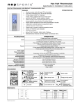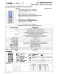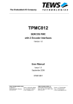
1
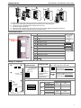
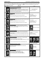
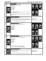
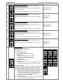
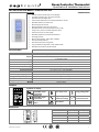
Room Controller Thermostat Specification & Installation Instructions VAV Thermostat with BACnet Communication Port ® TROB24T4XYZ1 Features: Attractive modern look with large LCD and backlight Icons driven information and 1 line of text information Selectable analog and digital output Precise achieve temperature control with programmable PI function Selectable Fahrenheit or Celsius scale Manual night set back override Multi level lockable access menu and set point Selectable internal or external temperature sensor (10 KΩ) Change over by contact or external temperature sensor Pressure sensor input / air flow program Selectable proportional control band and dead band Anti-freeze protection BACnet MS/TP @ 9600, 19200, 38400, 76800bps Automatic baud rate detection Automatic device instance configuration ® Copy and broadcast configuration to other TROB modules Selectable device instance and MAC address Technical Data TROB24T4XYZ1 3 Analog input universal (0-10 Vdc or thermistor or digital input dry contact) 2 Analog outputs 0-10 Vdc or 2-10 Vdc selectable (2mA max.) 4 Triac output (on/off, pulse 0 or 24 Vac, 250 mA max.), or 2 Floating output 22 to 26 Vac 50/60Hz 1 VA 10ºC to 40ºC [50ºF to 104ºF] -40ºC to 100ºC [-40ºF to 212ºF] Temperature: ±0.4ºC [0.8ºF] 0.5ºC to 5ºC [1ºF to 10ºF] adjustable 2 0.8 mm [18 AWG] minimum 0ºC to 50ºC [32ºF to122ºF] -30ºC to 50ºC [-22ºF to 122ºF] 5 to 95 % non condensing IP 30 (EN 60529) 160 g. [0.36 lb] Inputs Outputs Power supply Power consumption Set point range External sensor range Control accuracy Proportional band Electrical connection Operating temperature Storage & Transport Temperature Relative Humidity Degree of protection of housing Weight Interface .. .. Symbols on display AM PM Cooling ON 33,66,100% output A: Automatic Heating ON 33,66,100% output A: Automatic Communication Status MO TU WE TH FR SA SU %RH C F Menu set-up Lock Energy saving mode Programming mode (Technician setting) Celsius scale Cor F ºC: ºF: Fahrenheit scale Alarm status Dimensions B Dimension A B C D E E D ºF / º C A TROB24T4XYZ1-120926-ESL.doc Imperial (in) 2.85 4.85 1.00 2.36 3.27 Metric (mm) 73 123 24 60 83 C 1 TROB24T4XYZ1 Specification & Installation Instructions Mounting Instructions A B C D E CAUTION: Risk of malfunction. Remove power prior to separate thermostat cover from its base. A. Remove the screw (captive) holding the base and the front cover of the thermostat. B. Lift the front cover of the thermostat to separate it from the base. C. Pull wire through the base hole. D. Secure the base to the wall using wall anchors and screws (supplied). Make the appropriate connections. E. Mount the control module on the base and secure using the screw. Terminal Description Terminals 1 2 3 4 5 6 7 8 9 TB1 10 11 12 13 14 15 16 17 18 Description Common Common Common 24 Vac 24 Vac Triac output 1 (TO1) Triac (24 Vac EXT.) (TO1 & TO2) see Settings section Triac output 2 (TO2) Triac output 3 (TO3) Triac (24 Vac EXT.) (TO3 & TO4) see Settings section Triac output 4 (TO4) Analog input 1 (AI1) Analog input 2 (AI2) Analog input 3 (AI3) Analog output 1 (AO1) Analog output 2 (AO2) A+ Communication port RS-485 B- If set in floating, terminals 6-8 (floating 1), terminals 9-11 (floating 2) are as follow: TO1 close 1 TO2 open TO3 close 2 TO4 open F L O A T I N G Mode Selection Dip Switch (DS1) JP2 JP1 Settings on PC Board 24VAC 24VAC TB1 OFF: operation mode, ON: programming mode Not used 1 2 3 ON 5 6 1 2 3 7 8 JP6 End of line Temperature sensor 9 10 11 12 13 14 15 16 17 18 1 2 3 4 5 6 ON Analog input Dip switch 120 ohm end of line Set jumper on pin 2-3 on the last TROB of the RS-485 communication bus as illustrated above. Not used 4 1 2 3 ON Mode Selector DS2 Triac (digital) Output Signal Selection (JP1 for TO3 & TO4 - JP2 for TO1 & TO2) JP6 Connecting strip TB1 DS1 End Of Line (JP6) 24VAC 24VAC EXT. Jumper on left: All triac output signal is linked to internal 24 Vac. (Same 24Vac than thermostat) Jumper on right: All triac output signal is linked to external 24 Vac. (Different 24Vac than thermostat) Analog Input Dip Switch (DS2) AI1 ON 1 2 AI1 3 4 AI2 5 6 AI2 AI3 AI3 Thermistor 10KΩ Dry contact 0-10 Vdc Thermistor 10KΩ Dry contact 0-10 Vdc Thermistor 10KΩ Dry contact 0-10 Vdc ON OFF DS2.1 DS2.2 DS2.2 DS2.1 DS2.3 DS2.4 DS2.4 DS2.3 DS2.5 DS2.6 DS2.6 DS2.5 2 TROB24T4XYZ1 Specification & Installation Instructions Programming Mode When in this mode this symbol is displayed. Please press on button to advance to the next program function, press on button to return to preceding stage and press on button or to change value. You can leave the programming mode at any time, changed values will be recorded. Step Display Description Values Internal temperature sensor Calibration: Display shows “inside temper sensor offset” and temperature read by internal temperature sensor. Range : 10 to 40ºC [50 to 104ºF] You can adjust the calibration of the sensor by comparison with a known (max. offset ± 5 ºC) 1 thermometer. For example if thermostat has been installed in an area Increment: 0.1ºC [0.2ºF] where temperature is slightly different than the room typical temperature (thermostat place right under the air diffuser). ºF / º C C 2 C Minimum set point: Display shows “adjust minimum user setpnt” and the minimum set point temperature. Please select the desired minimum set point temperature. The minimum value is restricted by the maximum value. (step #3) 3 C 5 6 Maximum set point: Display shows “adjust maximum user setpnt” and the maximum set point Maximum range: temperature. 10 to 40ºC [50 to 104ºF] Please select the desired maximum set point temperature. Increment: 0.5ºC [1ºF] Default value: 30ºC [86ºF] The maximum value is restricted by the minimum value. (step #2) Locking the set point: Display shows “user setpnt locked” and the status of the function. You can lock or unlock the set point adjustment by end user. If locked, “yes” and lock symbol will appear. 4 C Minimum range: 10 to 40ºC [50 to 104ºF] Increment: 0.5ºC [1ºF] Default value: 15ºC [59ºF] Adjust internal set point: Display shows “adjust intern setpnt” and the set point temperature. Select the desired set point temperature; this one should be within the temperature range. Lock symbol will appear if the set point was locked at the previous step. Default value: Unlocked Set point range: 10 to 40ºC [50 to 104ºF] Increment: 0.5ºC [1ºF] Default value: 22ºC [72ºF] Set point value is restricted by the minimum and maximum value. (step #2 & 3) Adjust the control mode: Display shows “adjust temper control mode”. Cooling and heating symbols are also displayed. Select which control mode you want to authorize: Automatic cooling and heating, cooling or heating, heating only or cooling only. If you want to authorize this entire mode, choose Automatic mode. Default value: Automatic cooling and heating 7 8 Set On/Off function enable or disable: Display shows “enable on off control mode”. You can enable or disable the On/Off function in control mode adjustment by end user. Default value: Enable (YES) Set TO1 output signal: Display shows “select TO1 output signal”. Select which signal output you want for TO1 output. You can choose on/off, pulse or floating signal output. If you select floating, TO1 will be set close and TO2 open. Default value: floating 3 TROB24T4XYZ1 Step 9 Display Specification & Installation Instructions Description Set TO1 signal ramp: Display shows “select TO1 signal ramp”. Select which ramp you want for TO1. You can choose: Changeover ramp, Heating ramp 1, Heating ramp 2, Cooling ramp 1, Cooling ramp 2, OFF. Values Note: If “FLT” (floating) has been selected at step #8, the same ramp will be used for TO2. If “PULs” has been selected at step #8, you can only choose Heating ramp 1 or Heating ramp 2. 10 11 If you selected on/off signal at step #8, go directly to step #12. If you selected pulse signal at step #8 or OFF here, go directly to step #13. Set floating time: (If “FLT” has been selected at step #8) Display shows “set floating time in seconds” and the floating time value (in seconds). Please select desired value of the floating time signal. Set motor direction: Display shows “select motor direct reverse”. Select which direction you want for the motor. You can choose: Direct “clockwise” (0 to 90º) or Reverse “counter clockwise” (90 to 0º) Default value: Cr1 (Cooling ramp1) Range: 15 to 250 sec. Increment: 5 sec. Default value: 100 sec. Default value: direct (dir) Go to step #16. 12 Set TO1 on-off close position: (If “OnOf” has been selected at step #8) Display shows “select TO1 close percent” and the value of the close position of the TO1 output. Please select at which percentage you want TO1 to close: at 20%, 40%, 60% or 80% of the demand of the ramp that you selected at step # 9. Range: 20, 40, 60, 80 Increment: 20 % Default value: 40 (40% of the demand) Contact will automatically open at 0% of the demand. 13 14 Set TO2 output signal: Display shows “select TO2 output signal”. Select which signal output you want for TO2 output. You can choose on/off or pulse signal output. Default value: on-off Set TO2 signal ramp: Display shows “select TO2 signal ramp”. Select which ramp you want for TO2. You can choose: Changeover ramp, Heating ramp 1, Heating ramp 2, Cooling ramp 1, Cooling ramp 2, OFF. If “PULs” has been selected at step #13, you can only choose Heating ramp 1 or Heating ramp 2. If you selected pulse signal at step #13 or OFF here, go directly to step #16. Default value: Cr1 (Cooling ramp1) 4 TROB24T4XYZ1 Step 15 Display Specification & Installation Instructions Description Set TO2 on-off close position: (If “OnOf” has been selected at step #12) Display shows “select TO2 close percent” and the value of the close position of the TO2 output. Please select at which percentage you want TO2 to close: at 20%, 40%, 60% or 80% of the demand of the ramp that you selected at step # 14. Values Range: 20, 40, 60, 80 Increment: 20 % Default value: 40 (40% of the demand) Contact will automatically open at 0% of the demand. 16 Set TO3 output signal: Display shows “select TO3 output signal”. Select which signal output you want for TO3 output. You can choose on/off, pulse or floating signal output. If you select floating, TO3 will be set close and TO4 open. Default value: on-off 17 18 19 Set TO3 signal ramp: Display shows “select TO3 signal ramp”. Select which ramp you want for TO3. You can choose: Changeover ramp, Heating ramp 1, Heating ramp 2, Cooling ramp 1, Cooling ramp 2, OFF. Note: If “FLT” (floating) has been selected at step #16, the same ramp will be used for TO4. If “PULs” has been selected at step #16, you can only choose Heating ramp 1 or Heating ramp 2. If you selected on/off signal at step #16, go directly to step #20. If you selected pulse signal at step #16 or OFF here, go directly to step #21. Set floating time: (If “FLT” has been selected at step #16) Default value: Hr1 (Heating ramp 1) Display shows “set floating time in seconds” and the floating time value (in seconds). Please select desired value of the floating time signal. Range: 15 to 250 sec. Increment: 5 sec. Default value: 100 sec. Set motor direction: Display shows “select motor direct reverse”. Select which direction you want for the motor. You can choose: Direct “clockwise” (0 to 90º) or Reverse “counter clockwise” (90 to 0º) Default value: direct (dir) Go to step #24 20 Set TO3 on-off close position: (If “OnOf” has been selected at step #16) Display shows “select TO3 close percent” and the value of the close position of the TO3 output. Please select at which percentage you want TO3 to close: at 20%, 40%, 60% or 80% of the demand of the ramp that you selected at step # 17. Range: 20, 40, 60, 80 Increment: 20 % Default value: 40 (40% of the demand) Contact will automatically open at 0% of the demand. 21 Set TO4 output signal: Display shows “select TO4 output signal”. Select which signal output you want for TO4 output. You can choose on/off or pulse signal output. Default value: on-off 5 TROB24T4XYZ1 Step 22 Display Specification & Installation Instructions Description Set TO4 signal ramp: Display shows “select TO4 signal ramp”. Select which ramp you want for TO4. You can choose: Changeover ramp, Heating ramp 1, Heating ramp 2, Cooling ramp 1, Cooling ramp 2, OFF. Values If “PULs” has been selected at step #21, you can only choose Heating ramp 1 or Heating ramp 2. If you selected pulse signal at step #21 or OFF here, go directly to step #24. Default value: Hr2 (Heating ramp 2) 23 Set TO4 on-off close position: (If “OnOf” has been selected at step #21) Display shows “select TO4 close percent” and the value of the close position of the TO4 output. Please select at which percentage you want TO4 to close: at 20%, 40%, 60% or 80% of the demand of the ramp that you selected at step # 22. Range: 20, 40, 60, 80 Increment: 20 % Default value: 40 (40% of the demand) Contact will automatically open at 0% of the demand. Set AO1 analog signal ramp: Display shows “select AO1 analog ramp”. Select which ramp you want for analog signal on AO1. 24 You can choose: Changeover ramp, Heating ramp 1, Heating ramp 2, Cooling ramp 1, Cooling ramp 2, OFF. Default value: Cr1 (Cooling ramp1) Set AO2 analog signal ramp: Display shows “select AO2 analog ramp”. Select which ramp you want for analog signal on AO2. 25 You can choose: Changeover ramp, Heating ramp 1, Heating ramp 2, Cooling ramp 1, Cooling ramp 2, OFF. If “OFF” was selected for AO1, go to step #29. If “OFF” is selected for AO1 & AO2, go to step #32. 26 Default value: Hr1 (Heating ramp 1) Minimum voltage of AO1 output: (Only if “OFF” hasn’t been selected at step #24) Display shows “min vdc analog ao1 output” and the value of the minimum voltage of the AO1 output. Range: 0.0 to 10.0 Volt Please select the desired value of the minimum voltage of AO1 output. Increment: 0.1 Volt (This is the “zero” value) Default value: 0.0 Volt The minimum value is restricted by the maximum value. (step #27) 6 TROB24T4XYZ1 Step 27 Display Specification & Installation Instructions Description Maximum voltage of AO1output: (Only if “OFF” hasn’t been selected at step #24) Display shows “max vdc analog ao1 output” and the value of the maximum voltage of the AO1 output. Please select the desired value of the maximum voltage of AO1 output. (This is the “span” value) Values Range: 0.0 to 10.0 Volt Increment: 0.1 Volt Default value: 10.0 Volt The maximum value is restricted by the minimum value. (step #26) 28 29 Minimum position of AO1 output: (Only if “OFF” hasn’t been selected at step #24) Display shows “min POS ao1 output percent” and the value of the minimum position of the AO1 output. Range: 0 to 100% Please select the desired value of the minimum position of AO1 output. Increment: 5% Default value: 0% Minimum voltage of AO2 output: (Only if “OFF” hasn’t been selected at step #25) Display shows “min vdc analog ao2 output” and the value of the minimum voltage of the AO2 output. Range: 0.0 to 10.0 Volt Please select the desired value of the minimum voltage of AO2 output. Increment: 0.1 Volt (This is the “zero” value) Default value: 0.0 Volt The minimum value is restricted by the maximum value. (step #30) 30 Maximum voltage of AO2 output: (Only if “OFF” hasn’t been selected at step #25) Display shows “max vdc analog ao2 output” and the value of the maximum voltage of the AO2 output. Range: 0.0 to 10.0 Volt Please select the desired value of the maximum voltage of AO2 output. Increment: 0.1 Volt (This is the “span” value) Default value: 10.0 Volt The maximum value is restricted by the minimum value. (step #29) 31 32 Minimum position of AO2 output: (Only if “OFF” hasn’t been selected at step #25) Display shows “min POS ao2 output percent” and the value of the minimum position of the AO2 output. Range: 0 to 100% Please select the desired value of the minimum position of AO2 output. Increment: 5% Default value: 0% Set AI1 input signal: Display shows “select AI1 input signal”. Select which signal you want for AI1 input. You can choose: OFF (input not used), External temperature function: EtS (external temperature sensor 10KΩ), Changeover function: SENs (external change over sensor10KΩ), NoCl (change over contact normally cool), NoHt (change over contact normally heat), Night set back function: nSb (Night set back contact), Pressure function: PrSd (Differential pressure sensor 0-10vdc, PrSd=10V if P=1 ), PrSa (Velocity pressure sensor 0-10vdc, PrSa 10V=Vnom). If changeover is selected: When normally cool “NoCL” is selected, if contact is closed heating mode will be activated, if contact is opened cooling mode will be activated. When normally heat “NoHt” is selected, if contact is closed cooling mode will be activated, if contact is opened heating mode will be activated. When change over external sensor “SENs” is selected, heating mode will be activated when temperature read by external sensor is above the Change Over Set Point temperature, and cooling mode will be activated when temperature read by external sensor is under, see step #36. Default value: OFF If pressure sensor is selected: For pressure independent VAV system, you must do calibration by using “Air flow program mode”. (page 12) 7 TROB24T4XYZ1 Step Display Specification & Installation Instructions Description Set AI2 input signal: Display shows “select AI2 input signal”. Select which signal you want for AI2 input. You can choose: (Same as AI1 see step #32) 33 Note: AI1 input signal has priority to AI2, if you have selected the same function AI2 will not be functional. Set AI3 input signal: Display shows “select AI3 input signal”. Select which signal you want for AI3 input. You can choose: (Same as AI1 see step #32) 34 Values Default value: OFF Default value: OFF Note: AI1 & AI2 input signal have priority to AI3, if you have selected the same function AI3 will not be functional. External temperature sensor Calibration: (If ‘’EtS’’ has been selected at step #32, 33 or 34) 35 C Display shows “extern temper sensor offset” and the temperature read by the external temperature sensor (if connected on the selected input). If the sensor is not connected or short circuited, the display shows “Eror”. You can adjust the calibration of the external sensor by comparison with a known thermometer. Range: 0 to 50ºC [41 to 122.0ºF] (max. offset ± 5 ºC) Increment: 0.1ºC [0.2ºF] Change over set point temperature: (If ‘’SENs’’ has been selected at step #32, 33 or 34) 36 C Display shows “Ch over setpnt temper” and the change over set point Range: 10 to 40ºC [50 to 104ºF] temperature. Increment: 0.5ºC [1ºF] Please select the change over set point temperature. Note: heating mode will be activated when temperature read by external Default value: 24ºC [82ºF] sensor is above the change over set point temperature, and cooling mode will be activated when temperature read by external sensor is under. Night set back derogation time :(If ‘’nSb’’ has been selected at step #32, 33 or 34) Display shows “nsb delay override minutes” and the derogation time in minute. NSB symbol is also displayed. Range: 0 to 180min. Please select the desired derogation time, if no derogation time is Increment: 15min. desired select “0”. Default value: 120 min. 37 Heating Set point during Night set back: (If ‘’nSb’’ has been selected at step #32, 33 or 34) 38 C Display shows “night setback heating setpnt” and the value of the heating set point temperature during night set back. NSB and heating symbols are also displayed. Please select the heating set point temperature during night set back. The maximum value is restricted by the no occupancy cooling set point. (step # 39) Range: 10.0 to 40.0ºC [50 to 104ºF] Increment: 0.5ºC [1ºF] Default value: 16.0ºC [61ºF] Cooling Set point during Night set back: (If ‘’nSb’’ has been selected at step #32, 33 or 34) 39 C Display shows “night setback cooling setpnt” and the value of the cooling set point temperature during night set back. NSB and cooling symbols are also displayed. Please select the cooling set point temperature during night set back. The minimum value is restricted by the no occupancy heating set point. (step # 38) Range: 10.0 to 40.0ºC [50 to 104ºF] Increment: 0.5ºC [1ºF] Default value: 28.0ºC [82ºF] Set output signal used for pressure independent: (If ‘’PrSd’’ or ‘’PrSa’’ has been selected at step #32, 33 or 34) 40 Display shows “pressur indepen output”. Select which signal output is affected by pressure (connected to actuator). You can choose Floating 1 (TO1 & TO2), Floating 2 (TO3 & TO4), Analog 1 (AO1) or Analog 2 (AO2). Note: These selections can vary according to the choice made on steps #8 & #16. Default value: floating 1 8 TROB24T4XYZ1 Step 41 42 43 44 45 46 47 48 49 Display C Specification & Installation Instructions Description Values Proportional band of changeover ramp: Display shows “control ramp Ch over” and the value of the changeover ramp proportional band, cooling and heating symbols are also displayed. Proportional band range : 0.5 to 5.0ºC [1 to 10ºF] Please select the desired value of changeover ramp proportional band. Increment: 0.5ºC [1ºF] Default value: 2.0ºC [4ºF] C Proportional band of heating ramp1: Display shows “control ramp 1 HEATing” and the value of the heating ramp1 proportional band, heating symbol is also displayed. Please select the desired value of heating ramp1 proportional band. C Proportional band of heating ramp2: Display shows “control ramp 2 HEATing” and the value of the heating ramp2 proportional band, heating symbol is also displayed. Please select the desired value of heating ramp2 proportional band. C Proportional band of cooling ramp1: Display shows “control ramp 1 cooling” and the value of the cooling ramp1proportional band, cooling symbol is also displayed. Please select the desired value of cooling ramp1proportional band. C Proportional band of cooling ramp2: Display shows “control ramp 2 cooling” and the value of the cooling ramp2 proportional band, cooling symbol is also displayed. Please select the desired value of cooling ramp2 proportional band. C Dead band of changeover ramp: Display shows “control dead band Ch over” and the value of the changeover ramp dead band, cooling and heating symbols are also displayed. Please select the desired value of changeover ramp dead band. C Dead band of heating ramp1: Display shows “control dead band 1 heating” and the value of the heating ramp1 dead band, heating symbol is also displayed. Please select the desired value of heating ramp1 dead band. C Dead band of heating ramp2: Display shows “control dead band 2 heating” and the value of the heating ramp2 dead band, heating symbol is also displayed. Please select the desired value of heating ramp2 dead band. C Dead band in cooling ramp1: Display shows “control dead band 1 cooling” and the value of the cooling ramp1dead band, cooling symbol is also displayed. Please select the desired value of cooling ramp1 dead band. Proportional band range : 0.5 to 5.0ºC [1 to 10ºF] Increment: 0.5ºC [1ºF] Default value: 2.0ºC [4ºF] Proportional band range : 0.5 to 5.0ºC [1 to 10ºF] Increment: 0.5ºC [1ºF] Default value: 2.0ºC [4ºF] Proportional band range : 0.5 to 5.0ºC [1 to 10ºF] Increment: 0.5ºC [1ºF] Default value: 2.0ºC [4ºF] Proportional band range : 0.5 to 5.0ºC [1 to 10ºF] Increment: 0.5ºC [1ºF] Default value: 2.0ºC [4ºF] Dead band range : 0 to 5.0ºC [0 to 10.0ºF] Increment: 0.1ºC [0.2ºF] Default value: 0.3ºC [0.6ºF] Dead band range : 0 to 5.0ºC [0 to 10.0ºF] Increment: 0.1ºC [0.2ºF] Default value: 0.3ºC [0.6ºF] Dead band range : 0 to 5.0ºC [0 to 10.0ºF] Increment: 0.1ºC [0.2ºF] Default value: 0.3ºC [0.6ºF] Dead band range : 0 to 5.0ºC [0 to 10.0ºF] Increment: 0.1ºC [0.2ºF] Default value: 0.3ºC [0.6ºF] 9 TROB24T4XYZ1 Step 50 Display C Specification & Installation Instructions Description Dead band in cooling ramp2: Display shows “control dead band 2 cooling” and the value of the cooling ramp2 dead band, cooling symbol is also displayed. Please select the desired value of cooling ramp2 dead band. 51 Anti-cycling delay cooling contact (protection for compressor): Display shows “cooling anti cycle minutes” and the value (in minutes) of the delay to activate / reactivate cooling contact. Please select the desired value of the delay cooling contact. 52 Integration time factor setting: Display shows “adjust intgral time in seconds” and the time in seconds for the integration factor compensation. Please select the desired value of the integration factor compensation. 53 Enable or disable anti-freeze protection: Display shows “enable anti freeze protect”. You can enable or disable the Anti-freeze function. When enabled, if temperature drop to 4ºC [39ºF], heat will start even if thermostat is in OFF mode. Heat will stop when temperature reach 5ºC [41ºF]. Auto bauds rate: Display scrolls “auto BAUDS RATE”. You can enable or disable the Auto bauds rate function. 54 55 Dead band range : 0 to 5.0ºC [0 to 10.0ºF] Increment: 0.1ºC [0.2ºF] Default value: 0.3ºC [0.6ºF] Range: 0 to 15 min. Increment: 1 min. Default value: 2 min. Range: 0 to 250 seconds Increment: 5 seconds Default value: 0 seconds Default value: Disable (NO) Default value: Enable (YES) When enabled, the thermostat automatically configures its baud rate by detecting the network speed upon connection. When enabled, the value cannot be changed manually. When disabled, the baud rate must be set manually (go to step #56). Auto bauds, current baud: Display scrolls “auto comport BAUDS RATE. and the detected baud rate. Go to step #57. Communication bauds rate: Display scrolls “ADJUST COMPORT BAUDS RATE” and the value of the baud rate in kbps. Select the desired baud rate: 9.6. 19.2, 38.4, 76.8. 56 Communication MSTP/Mac address: Display shows “adjust MSTP Mac address”. Select the desired MSTP/MAC for communication. 57 Each device must have a unique MAC address on a network. 58 Values Range: 9600, 19200, 38400, 76800 Range: 9600, 19200, 38400, 76800 Default value: 76.8 kbps Range: 0 to 254 Increment: 1 Default value: 1 Copy config: Display shows “copy config”. Select “YES” if you want to copy the configuration from this device to others on the network. 10 TROB24T4XYZ1 Step 59 60 Display Specification & Installation Instructions Description Select “start” address: Display shows “Select begin address”. Select the first address you want to copy to. Values For example if you select MAC address 1 here and 54 in the next step, all the devices from 1 to 54 will receive the configuration of the current device. Select “end” address: Display shows “Select end address”. Select the last address you want to copy to. You cannot copy to more than 64 addresses at once. Range: 0-254 Default value: 0 Range: begin address + 63 Default value: begin address Copy config result: Display shows “Copy config succeed” if everything went ok. 61 Error message example: Program Mode Error for address 7 If not, you will be able to scroll the addresses and see the error message associated with each address. See the Annex section for the complete list of error messages. 62 Communication device instance: Display scrolls “ADJUST DEVICE INSTANC 0153000”. To change the device, select “YES” and go to next step. If the device instance is not changed in programming mode (step #62 & 63), it will be automatically modified according to the MAC address selected at step #57. Default value: no If you do not want to change the device, go directly to step #1. Default value: NO Communication device instance (cont’d): Display scrolls the device address value. You can modify the device address by increasing or decreasing the 63 blinking digit with “” or “”buttons. To modify the next digit, on right, , to return to the previous digit press . press ºF / º C Range: 0 to 4194302 Increment: 1 digit Default value: 0153001 11 TROB24T4XYZ1 Specification & Installation Instructions Air Flow & BACnet Program Mode (Available when in Operation Mode; DS1-1 OFF position) Push on both and buttons for 5 seconds to access the user air flow program mode. This menu is accessible only If ‘’PrSd’’ or ‘’PrSA’’ has been selected at step #32, 33 or 34. Step Display Description Values Password: Display shows “enter passwrd” and 000. You have 1 minute to enter the password by incrementing or decrementing the blinking digit with and buttons.To modify Password: 637 (corresponding to NEP) F1 , to return to digit on the left press . following digit on right press When the password is entered press on . If you do a mistake, you will see “Eror” and the thermostat will return in operation mode. You need to redo this step. ºF / º C ºF / º C When the password is entered and you are in the balancing mode, this symbol to the next program function, press on the ºF / º C is displayed. Press on the button to return to previous step and press on the or button to advance button to change value. The system will exit the menus and return to normal function if you navigate through the entire menu or if no button is pressed for 5 minutes, changed values will be saved. Step Display Description Auto bauds rate: Display scrolls “auto BAUDS RATE”. You can enable or disable the Auto bauds rate function. B1 Values Default value: Enable (YES) When enabled, the thermostat automatically configures its baud rate by detecting the network speed upon connection. When enabled, the value cannot be changed manually. When disabled, the baud rate must be set manually (go to step #B3). Auto bauds, current baud: Display scrolls “auto comport BAUDS RATE. and the detected baud rate. B2 Go to step #B4. Range: 9600, 19200, 38400, 76800 Communication bauds rate: Display scrolls “ADJUST COMPORT BAUDS RATE” and the value of the baud rate in kbps. Select the desired baud rate: 9.6, 19.2, 38.4, 76.8. Range: 9600, 19200, 38400, 76800 Default value: 76.8 kbps B3 MAC address: Display scrolls “ADJUST MSTP mac address” and the value of the MAC address. Select the desired MSTP/MAC for communication. Range: 0 to 254 B4 Each device must have a unique MAC address on a network. Default value: 0 B5 Copy config: Display shows “copy config”. Select “YES” if you want to copy the configuration of this device to others on the network. Select “start” address: Display shows “Select begin address”. Select the first address you want to copy to. B6 For example if you select MAC address 1 here and 54 in the next step, all the devices from 1 to 54 will receive the configuration of the current device. Range: 0-254 Default value: 0 12 TROB24T4XYZ1 Step Display Specification & Installation Instructions Description Select “end” address: Display shows “Select end address”. Select the last address you want to copy to. You cannot copy to more than 64 addresses at once. B7 Copy config result: Display shows “Copy config succeed” if everything went ok. If not, you will be able to scroll the addresses and see the error message associated with each address. B8 Values Range: begin address + 63 Default value: begin address Error message example: Program Mode Error for address 7 See the Annex section for the complete list of error messages. Communication device instance: Display scrolls “ADJUST DEVICE INSTANC 0153000”. To change the device instance, select “YES” and go to next step. If the device instance is not changed in programming mode (step #62 & 63 or B9 & B10), it will be automatically modified according to the MAC address selected by the dip switch on the CONTROLLER. B9 Default value: NO If you do not want to change the device, go directly to step #F2. Communication device instance (cont’d): Display scrolls the device address value. You can modify the device address by increasing or decreasing the blinking digit with “” or “”buttons. To modify the next digit, on right, . To return to the previous digit press . press B10 ºF / º C F2 C Internal temperature sensor calibration: Display shows “inside temper sensor offset” and temperature read by internal temperature sensor. You can adjust the calibration of the sensor by comparison with a known thermometer. For example if thermostat has been installed in an area where temperature is slightly different than the room typical temperature (thermostat place right under the air diffuser). Range: 0 to 4194302 Increment: 1 digit Default value: 0153001 Range : 10 to 40ºC [50 to 104ºF] (max. offset ± 5 ºC) Increment: 0.1ºC [0.2ºF] External temperature sensor calibration: (If ‘’EtS’’ has been selected at step #32, 33 or 34 of programming mode) F3 F4 C Display shows “extern temper sensor offset” and the temperature read by the external temperature sensor (if connected on the selected input). If the sensor is not connected or short circuited, the display shows “Eror”. You can adjust the calibration of the external sensor by comparison with a known thermometer. Pressure filter setting: Display shows “pressur filter time in seconds” and the time in seconds for the numeric filter applied to the pressure analog input. Please select the desired value of the numeric filter. This filter stabilize the reading and slowed down the answer of the system F5 Integration time factor setting: Display shows “airflow intgral time in seconds” and the time in minutes for the integration factor compensation. Please select the desired value of the integration factor compensation. Range: 0 to 50ºC [41 to 122.0ºF] (max. offset ± 5 ºC) Increment: 0.1ºC [0.2ºF] Range: 1 to 10 seconds Increment: 1 seconds Default value: 2 seconds Range: 0 to 60 min. Increment: 1 min. Default value: 0 min. 13 TROB24T4XYZ1 Step Display Specification & Installation Instructions Description Air flow K factor: Display shows “adjust airflow kfactor vnom” and the value of the k factor or the V nominal according to your pressure sensor selection (‘’PrSd’’ or ‘’PrSa’’ selected at step #32, 33 or 34) F6 PrSd …V = k√∆P when ∆P=1 (10.00V) PrSa … Vnom =10.00V F7 Please select the desired value of k factor or the V nominal. Minimum cooling airflow: Display shows “minimum cooling airflow” and the value of the minimum airflow in cooling. Please select the desired value of the minimum airflow in cooling. The minimum value is restricted by the maximum value. (step #F8) F8 Maximum cooling airflow: Display shows “maximum cooling airflow” and the value of the maximum airflow in cooling. Please select the desired value of the maximum airflow in cooling. The maximum value is restricted by the minimum value. (step #F7) F9 Minimum heating airflow: Display shows “minimum heating airflow” and the value of the minimum airflow in heating. Please select the desired value of the minimum airflow in heating. The minimum value is restricted by the maximum value. (step #F10) F10 Maximum heating airflow: Display shows “maximum heating airflow” and the value of the maximum airflow in heating. Please select the desired value of the maximum airflow in heating. The maximum value is restricted by the minimum value. (step #F9) Values Range: 100 to 9995 Increment: 5 Default value: 1200 Range: 0 to maximum cooling airflow Increment: 5 Default value: 100 Range: minimum cooling airflow to k factor or V nominal Increment: 5 Default value: 1000 Range: 0 to maximum heating airflow Increment: 5 Default value: 100 Range: minimum heating airflow to k factor or V nominal Increment: 5 Default value: 1000 Enable or disable airflow balancing: Display shows “enable airflow balance”. You can enable or disable the balancing airflow function. F11 F12 F13 If you do not need to balance system, select No. You will leave the balancing menu and return to operation mode. If you want to balance system, select YES. In this case, you will leave the balancing menu and return to operation mode if no button is pressed for 30 minutes, changed values will be saved. Minimum airflow calibration: Display shows “minimum airflow” and the value of the minimum airflow detected by the pressure sensor. The thermostat will send a signal to the actuator close the VAV boxe at minimum airflow. When the value on thermostat is stable, you can adjust the calibration of the sensor by comparison with the reading on a manometer or a balometer. If you can’t stabilize the system, you will need to increase the filter value. (step #F4) Maximum airflow calibration: Display shows “maximum airflow” and the value of the maximum airflow detected by the pressure sensor. The thermostat will send a signal to the actuator open the VAV boxe at maximum airflow. When the value on thermostat is stable, you can adjust the calibration of the sensor by comparison with the reading on a manometer or a balometer. If you can’t stabilize the system, you will need to increase the filter value. (step #F4) Come back to step #F11 Default value: Disable (No) Range: 0 to k factor or V nominal (max. offset ± ½ value) Increment: 1 Range: 0 to k factor or V nominal (max. offset ± ½ value) Increment: 1 14 TROB24T4XYZ1 Specification & Installation Instructions Annex – Error Codes for Copy Config Succeed: If there are problems with the copy, user will be able to scroll through the range of addresses to find out the error codes for each address. CC1 In the event that some worked, they will be labelled as “copy config succeed” with the address shown underneath. Program mode error: Display shows “copy config progerr” with the address shown underneath. CC2 The target device is in program mode, the copy is not possible. Device type error: Display shows “copy config typeerr” with the address shown underneath. CC3 The target device is not the same type as the source, the copy is not possible. For example trying to copy a TRO configuration to an EVC. Model type error: Display shows “copy config modlerr” with the address shown underneath. CC4 The target device is not the same model as the source, the copy is not possible. For example trying to copy a TROB24T4XYZ1 configuration to an TROB24T4-OE1. Memory error: Display shows “copy config mem err” with the address shown underneath. CC5 The target device is not the same application version (eeprom) as the source, the copy is not possible. Slave address: Display shows “copy config Slave” with the address shown underneath. CC6 The target device is at a slave address. It cannot respond to the master if the copy succeeded or not. User should manually check to make sure copy was done correctly or avoid using slave addresses (128254). Communication error: Display shows “copy config commerr” with the address shown underneath. CC7 No responses were received from the target device (after 3 tries). Either the address doesn’t exist (not used) or there is a problem with wiring/noise. 15 TROB24T4XYZ1 Operation mode Step A Specification & Installation Instructions Description Display At powering up, thermostat will light display and activate all LCD segments during 2 seconds. Illuminating the LCD. To illuminate the LCD, you just have to push onto any of the 4 buttons. LCD will light for 4 seconds. Temperature display In operation mode, thermostat will automatically display temperature read. If “OFF”, “- - -” and alarm symbol are displayed, the temperature sensor is not connected or short circuited. To change the scale between ºC and ºF, press on button. Air flow display To display the air flow, press on button for 5 seconds. When in this mode “airflow” is displayed. Air flow value will be displayed during 5 seconds. Set point display and adjustment C ºF / º C To display the set point, press two times on or . Set point will be displayed during 3 seconds. B To adjust set point, press on or while the temperature set point is displayed. Note: If set point adjustment has been locked, C D C C symbol will be displayed. Night set back (NSB) : When thermostat is in night set back mode, NSB symbol is displayed, so set point for cooling and/or heating are increased as per the setting made in programming mode. If not locked, night set back can be derogated for a predetermined period by pressing onto any of the 4 buttons. During period of NSB derogation the symbol will flash. If NSB does not flash, the derogation period is finished or the Night set back derogation has been locked in programming mode. C Control mode selection : To verify which control mode is set, press on button. Control mode will be displayed during 5 seconds. To change of control mode, press on button while control mode is displayed. You can choose one of the following: Automatic Cooling or Heating Cooling and Heating OFF Cooling only Heating only Note: These selections can vary according to the choice made on steps #6 & #7. Recycling at end of life ® At end of life, please return the thermostat to your Neptronic local distributor for recycling. If you need to find the nearest Neptronic authorized distributor, please consult www.neptronic.com. ® 16