1
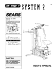
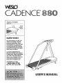
WESLO
CADENCE °88@
Model No. WLTL88060
Serial No.
Serial
Number
Decal
QUESTIONS?
As a manufacturer, we are committed to providing complete
customer satlsfaction. If you
have questlons, or find that there
are missing or damaged parts,
we will guarantee you complete
satisfaction through dlrect assistance from our factory.
TO AVOID UNNECESSARY
DELAYS, PLEASE CALL DIRECT
TO OUR TOLL-FREE CUSTOMER
HOT LINE. The trained technicians on our Customer Hot Line
will provide immediate assistance, free of charge to you.
CUSTOMER
HOT LINE:
1-800-999-3756
Mon.-Frl.,
6 a.m.-6 p.m. MST
USER'S MANUAL
VVE LO
CADENCE"
TABLE OF CONTENTS
IMPORTANT PRECAUTIONS .................................................................
BEFORE YOU BEGIN .......................................................................
WARNING DECAL PLACEMENT ..............................................................
ASSEMBLY ...............................................................................
OPERATION AND ADJUSTMENT
.............................................................
TROUBLE-SHOOTING AND STORAGE ........................................................
CONDITIONING GUIDELINES ...............................................................
PART LIST ...............................................................................
EXPLODED DRAWING .....................................................................
ORDERING REPLACEMENT PARTS ..................................................
LIMITED WARRANTY .............................................................
2
3
4
5
5
7
11
13
14
15
Back Cover
_ .Back Cover
i MPO RTA NT
..................................
! i:i:i:!_!:
;iilfol
3
BEFORE YOU BEGIN
Thank you for selecting the WESLO CADENCE ®880
treadmill. The CADENCE 880 treadmill blends
advanced technology with innovative design to offer
you an excellent form of cardiovascular exercise, in the
convenience and privacy of your home.
For your benefltt read this manual carefully before
using the treadmill. If you have additional questions,
please call our Customer Service Department toll-free
at 1-800-999-3756, Monday through Friday, 6 a.m.
until 6 p.m. Mountain Time (excluding holidays). To
help us assist you, please note the product model
number and serial number before calling. The model
number is WLTL88060. The serial number can be
found on a decal attached to the treadmill (see the
front cover of this manual for the location).
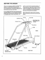
Before reading further, please review the drawing
below and familiarize yourself with the parts that are
labeled.
Console
Towel Rack
SAFEKEY_/Cli
Bottle Holder
(Water Bottle is not
included)
Accessory
'Pulse Sensor
FRONT
Motor
Circuit Breaker
Endcaps
Walking Belt
Power C_
Foot Rail
Rear Roller
Adjustment Bolts
Leg
RIGHT SIDE
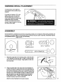
WARNING DECAL PLACEMENT
The decal shown at the right has
been placed on the console of your
treadmill.
If the decal is missing, or if it is not
legible, please call our Customer
Service Department, toll-free, to
order a free replacement decal (see
ORDERING REPLACEMENT
PARTS on the back cover of this
manual). Apply the decal in the location shown at the right.
ASSEMBLY
Set the treadmill in a cleared area and remove all packing materials. Do not dispose of the packing materials until
assembly is completed. Refer to the drawings below to identify small parts used in assembly. Assembly requires
an adjustable wrench _
(not Included).
©
3/8" x 1" Bolt (7)-3
Flange Nut (54)-2
3/8" x 1 1/2" Washer
.
2,
Raise the Upright (20) to the vertical position. Slide the 3/8" x
1 1/2" Washer (27) onto the 3/8" x 1" Bolt (7). Insert the Bolt
into the lower end of the Upright. Finger tighten the Bolt into
the Frame (46).
If there are plastic ties in the upper ends of the Handrails (1),
cut them off. Insert the upper end of one of the Handrails into
the Console Housing (4). (Note: The two Handrails are identical. Due to the manufacturing process, there is a dimple near
the lower end of each Handrail. It makes no difference which
side the dimple is on when the Handrails are assembled.)
Finger tighten a 3/8" x 1" Bolt (7) into the plate under the
Console Housing (4) and into the Handrail.
Attach the other Handrail (1) in the same manner.
20
.
Insert a 5/16" x 3" Bolt (71) into the lower end of the right
Handrail (1) and into the Frame (46). Reach under the Frame
and tighten a Flange Nut (54) onto the end of the Bolt.
Attach the other Handrail (1) (not shown) in the same manner.
Tighten all bolts used in steps 1 through 3.
46
54
Remove the paper backing from the Adhesive Clip (16). Press
the Adhesive Clip onto the Right Endcap (45) in the indicated
location. Press the Allen Wrench (41) into the Adhesive Clip,
4,
.
The Console (5) requires three "AA" batteries (not included). Alkaline batteries are recommended.
5
5
Slide up the Battery Cover (36). Press three batteries into the battery compartment, with the negative (-) ends of the batteries touching the springs. Close the Battery Cover.
Make sure that all parts are tightened before you use the treadmill. Note: To protect the floor or carpet from
damage, place a mat beneath the treadmill.
OPERATION AND ADJUSTMENT
THE PERFORMANT
LUBE TM WALKING
BELT
Your treadmill features a walking belt coated with
PERFORMANT LUBE TM, a high-performance lubricant.
IMPORTANT: Never apply silicone spray or other
substances to the walking belt or the walking platform. They will deteriorate the walking belt and
cause excessive wear.
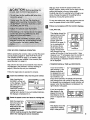
risk of electric shock. This product is equipped with a
cord having an equipment-grounding conductor and a
grounding plug. Plug the power cord Into a surge
protector, and plug the surge protector into an
appropriate outlet that is properly installed and
grounded in accordance with all local codes and
ordinances.
This product is for use on a nominal 120-volt circuit,
and has a grounding plug that looks like the plug illustrated in drawing 1 below. A temporary adapter that
looks like the adapter illustrated in drawing 2 may be
used to connect the surge protector to a 2-pole receptacle as shown in drawing 2 if a properly grounded outlet is not available.
HOW TO PLUG IN THE POWER CORD
The temporary adaPter should be used only until a
properly grounded outlet (drawing 1) can be installed
by a qualified electrician.
The green-colored rigid ear, lug, or the like extending
from the adapter must be connected to a permanent
ground such as a properly grounded outlet box cover.
Whenever the adapter is used it must be held in place
by a metal screw. Some 2-pole receptacle outlet box
covers are not grounded. Contact a qualified electrician to determine if the outlet box cover is
Your treadmill, like any other type of sophisticated
electronic equipment, can be seriously damaged by
sudden voltage changes in your home's power.
Voltage surges, spikes, and noise interference can
grounded before using an adapter.
result from weather conditions or from other appliances being tumed on
or off. To decrease the
possibility of your
treadmill being damTreadmill
.j__
Grounded Outlet Box
aged, always use a
surge protector (not
_"D_..I
__ Grounding Pin
Included) with your
Grounding
treadmill.
Surge protectors are
sold at most hardware
stores and department
stores. Use only a ULlisted surge protector,
rated at 15 amps, with a
14-gauge cord of five
feet or less in length.
This product must be
grounded. If it should
malfunction or break
down, grounding provides a path of least
resistance for electric
current to reduce the
'_unding
\Grounded
Plug
Outlei
Surge Protector
7
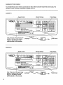
DIAGRAM OF THE CONSOLE
Your treadmill has one of the two consoles shown below. Both consoles feature the same modes. The
operation of both consoles is described on pages 9 and 10.
CONSOLE 1
Monitor Displays
Speed Control
WESLO
Fit
• I
ITO_J
ZC_S
41NG
s
G
J
v ; d •
WAJ_vl
_v.
UP
Pulse Display
EIs
FAT
. bURN
€ Ir
ABIOE_
•
n Ic
J
|
_
_,
inHJfmi
1
L(.-IJ ]
F I,o,c,I
l"v_/ DL_AN_
I, s.,'l ]*I"
THUMB PJL.SE
SPEED
in
STEP_,STEP
.;:.i_, INSE_ S'_EK_Y
OPEItATION:
:_.
•
=
PE_
SPEEDRESETM_ .........
//
I'_SS ON/CLEA_I_1"TON
k_nlL
•
::,._-. RESEtSPEED,11_ENBETTO D_BJRED
LEVEL
ON/CLEAR
20
I=s
141sI 141s
30
tto
13S
IIS
1_10
410
50
60
110
10|
lS3
14S
123
140
113
130
70
9S
11@
t2S
80
to
_o3
r-at
Burn
Max.
Fat
11s
Aerobic
Note: If there is a thin sheet of clear
plastic on the face of the console,
remove it. Be careful to avoid
spilling liquids on the console.
CONSOLE2
Speed Control
WESLO
Fit
n
e
s
s
Monitor Displays
t
Guide
w_k_ UP
E
t_T_
I e
€ t
,_B_O_C
r
e
n
I
€
I'_
4ES
//
$
I ....
1
1
.....
.
--..
.
,J
SPEED
i
i
i
ii
OPEt _T_ON: .._: PRE_Oe4/l_ES_i_,rrtoN
:_.:. RESE1Sl_d_, _EN
Note: If there is a thin sheet of clear
plastic on the face of the console,
remove it. Be careful to avoid
spilling liquids on the console.
8
Pulse Display
/
,_T 10 DEStREDL_,'L%
I
i
]
c._/FAT _
PULSE
_,,p,,_,,,wr._:
"
P0/_E TRAINING ZONES
70 Its
eO I _ol
I _1o I t:s
I
_: J _s I
ON / RESET
Pulse Sensor
g precau_iohs
After you have moved the speed control to the
RESET position, slowly move it to the right until the
walking belt begins to move at slow speed.
Carefully step onto the walking belt and begin exercising• Change the speed of the walking belt as
desired by moving the speed control.
'
To stop the walking belt, step onto the foot rails and
move the speed control to the RESET position.
Follow your progress with the monitor displays.
• CALJFAT CAL.
This display shows the
approximate numbers
of ca/ories and fat
ca/ories you have
burned. (See FAT
BURNING on page 13
for an explanation of
fat calories.) Every
STEP BY STEP CONSOLE OPERATION
Before operating the console, make sure that the power
cord is properly plugged in. (See HOW TO PLUG IN
THE POWER CORD on page 7.) In addition, make
sure that batteries are installed in the console. (See
assembly step 5 on page 6.)
• TIME/DISTANCE
Step onto the foot rails of the treadmill. Next, find the
clip attached to the SAFEKEY (see the drawing on
page 8). Slide the clip onto your waistband.
Insert the SAFEKEY fully into the power switch.
Note: Inserting the
SAFEKEY will not turn
on the displays. The displays will turn on when
the ON/CLEAR (or
ON/RESET) button is
pressed or when the
walking belt is started, if you just installed batteries,
the displays will already be on.
Reset the speed control and start the walking belt.
B
Slide the speed control to the left to the
RESET position.
Note: Each time the i pit.===
eu=ll=
,ioc*.=._==
walking belt is
stopped, the speed
control must be moved to the RESET position
before the walking belt can be restarted.
(or TIME and DISTANCE)
If you have monitor 1
1
(see drawing 1), this
in.._n
;u._u
display shows both
the elapsed time and
the total distance you
have walked or run.
Every seven seconds, the display will automatically change from one number to the other. When
the elapsed time is displayed, the left indicator will
appear; when the total distance is displayed, the
right indicator will appear.
Follow the steps below to operate the console.
B
seven seconds, the
Indicators
display will automatically change from one
number to the other. If you have monitor 1 (see
drawing 1), an =F"will appear when the number of
fat calories is displayed, if you have monitor 2
(see drawing 2), indicators will show which number is displayed•
If you have monitor 2
(see drawing 2), the
elapsed time and the
total distance will be
shown in separate displays.
• SPEED
!
This display shows the
speed of the walking
belt, in miles per hour.
9
El
The displays can be
reset, if desired, by
pressing the ON/CLEAR
(or ON/RESET) button.
B
ONICL_e
"II
When you are finished exercising, stop the
walking belt and
remove the
SAFEKEY.
Measure your pulse, if desired.
To use the pulse
sensor, stand on
the foot rails and
place your thumb
on the pulse sensor as shown.
The pulse sensor
is pressure-activated. Fully press
down the pulse sensor. Do not press too hard, or
the circulation In your thumb will be restricted,
and your pulse will not be detected. Next, slightly
raise your thumb until the heart-shaped indicator in
the PULSE display
flashes steadily (if you
have monitor 1, see
drawing 1; if you have
monitor 2, see drawing
2). Hold your thumb at
Indicator
this level. After 5 to 10
seconds, your pulse will
be shown. Hold your
thumb on the sensor for
another 15 seconds for
Indicator
the most accurate reading. If the displayed
pulse appears to be too high or too low, or if your
pulse is not displayed, lift your thumb off the sensor
and allow the display to reset. Press down again on
the sensor as described above.
Step onto the foot rails,
stop the walking belt,
and remove the SAFEKEY from the console.
Store the SAFEKEY in a secure place. After the
SAFEKEY is removed, the displays will remain
on for about five minutes.
Note: Any time that the walking belt is stopped
and no console buttons are pressed for five minutes, the displays will automatically turn off.
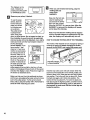
HOW TO CHANGE THE INCLINE OF THE TREADMILL
The incline of the treadmill can be changed by raising or
lowering the back end. Before changing the incline,
remove the SAFEKEY and unplug the power cord.
lilt ;c31
Make sure that your thumb is positioned as shown,
and that you are applying the proper amount of pressure to the pulse sensor. Try the sensor several
times until you become familiar with it. Remember to
stand still while measuring your pulse.
10
Hold the Endca
in these locations
Incline
Leg
Hold the rear roller cover with both hands. When the
back end of the treadmill is in the lowest position, the
incline is about 10%. Raise the back end until it clicks
into position. The incline will then be about 5%. Raise
the back end again until it clicks into position. The
incline will then be about 3%. To lower the back end,
first raise it past the highest position, and then lower it.
CAUTION: Before exercising, push on the back of
the treadmill to make sure that the incline legs are
locked In position.
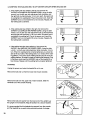
TROUBLE-SHOOTING
AND STORAGE
Most treadmill problems can be solved by following the simple steps below. Find the symptom that
applies to your treadmill and follow the steps listed. If further assistance is needed, please call our
Customer Service Department toll-free at 1-800-999-3756, Monday through Friday, 6 a.m. until 6 p.m.
Mountain Time (excluding holidays).
1. SYMPTOM:
THE POWER DOES NOT TURN ON
a. Make sure that the power cord is plugged into a surge protector, and that the surge protector is plugged into
.. a properly grour_dedoutlet. (See HOW TO PLUG IN THE POWER CORD on page 7.) Use only a UL-listed
surge protector, rated at 15 amps, with a 14-gauge cord of five feet or less in length.
b. After the power cord has been plugged in, make sure that the SAFEKEY is fully inserted into the console.
(See page 9.)
c. Check the circuit breaker located on the treadmill frame near
the power cord. If the switch protrudes as shown, the circuit
breaker has tripped. To reset the circuit breaker, wait for five
minutes and then press the switch back in.
Tripped
Reset
2. SYMPTOM: THE POWER TURNS OFF DURING USE
a. Check the circuit breaker located on the treadmill frame near the power cord. If the circuit breaker has
tripped, the switch will protrude. (See the drawing above.) To reset the circuit breaker, wait for five minutes
and then press the switch back in.
b. Make sure that the power cord is plugged in.
c. Remove the SAFEKEY from the console. Reinsert the SAFEKEY fully into the console.
3. SYMPTOM:
THE DISPLAYS OF THE CONSOLE DO NOT FUNCTION PROPERLY
a. Check the batteries in the console. (See assembly step 5 on page 6). Most problems are the result of
drained batteries.
4. SYMPTOM:
THE WALKING BELT SLOWS WHEN WALKED ON
a. Use only a UL-listed surge protector, rated at 15 amps, with a 14-gauge cord of five feet or less in length.
b.
If the walking belt is overtightened, treadmill performance
maydecrease and the walking belt may be permanently damaged. Remove the SAFEKEY and UNPLUG THE POWER
CORD. Using the included allen wrench, turn both rear roller
adjustment bolts counterclockwise, 1/4 of a turn. When the
walking belt is properly tightened, you should be able to lift
each side of the walking belt 2 to 3 inches off the walking
platforh_. The center of the walking belt should just touch the
walking platform. Be careful to keep the walking belt centered. Plug in the power cord, insert the SAFEKEY and run
the treadmill for a few minutes. Repeat until the walking belt
is properly tightened.
J
2"-3"
Rear Roller
Adjustment Bolts
c. If the walking belt still slows when walked on, please call our Customer Service Department, toll-free.
11
5. SYMPTOM: THE WALKING BELT IS OFF-CENTER
OR SLIPS WHEN WALKED ON
a. If the walking belt has shifted to the left, first remove the
SAFEKEY and UNPLUG THE POWER CORD. Using the allen
wrench, turn the left rear roller adjustment bolt clockwise, and
the right bolt counterclockwise, 1/4 of a turn each. Be careful not
to overtighten the walking belt. Plug in the power cord, insert the
SAFEKEY and run the treadmill for a few minutes. Repeat until
the walking belt is.centered.
b. If the walking belt has shifted to the right, first remove the
SAFEKEY and UNPLUG THE POWER CORD. Using the allen
wrench, turn the left rear roller adjustment bolt counterclockwise,
and the right bolt clockwise, 1/4 of a turn each. Be careful not to
overtighten the walking belt. Plug in the power cord, insert the
SAFEKEY and run the treadmill for a few minutes. Repeat until
the walking belt is centered.
c. If the walking belt slips when walked on, first remove the
SAFEKEY and UNPLUG THE POWER CORD. Using the allen
w:ench, tJrn both rear roller adjustment bolts clockwise, 1/4 of a
turn. When the walking belt is correctly tightened, you should be
able to lift each side of the walking belt 2 to 3 inches off the walking platform. The center of the walking belt should just touch the
walking platform. Be careful to keep the walking belt centered. Plug
in the power cord, insert the SAFEKEY and run the treadmill for a
few minutes. Repeat until the walking belt is properly tightened.
STORAGE
Unplug the power cord when the treadmill is not in use.
Remove the bolt and nut from the lower end of each handrail.
Remove the bolt from the upper end of each handrail. Slide the
handrails out of the console housing.
Remove the bolt and washer from the lower end of the upright. Lay
the upright on the treadmill. Keep all hardware in a secure location.
It is recommended that the batteries be removed from the console
and the treadmill be covered during extended periods of storage.
__
12
"7." ° ..o ,_
move
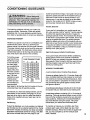
CONDITIONING
GUIDELINES
stored fat calories for energy. If your goal is to burn fat,
adjust the speed and incline of the treadmill until your
heart rate is near the first or second number in your
training zone. It may also be helpful to set the speed
control on the console to FAT BURN to help you maintain the proper intensity level. (See page 9.)
Aerobic Exercise
The following guidelines will help you to plan your
exercise program. Remember--these
are general
guidelines only. For more detailed exercise information, obtain a reputable book or consult your physician.
EXERCISE INTENSITY
Whether your goal is to burn fat or to strengthen your
cardiovascular system, the key to achieving the
desired results is to exercise with the proper intensity.
The proper intensity level can be found by using your
heart rate as a guide. The chart below shows recommended heart rates for fat burning and aerobic exercise. (This chart is also found on the console.)
To find the proper
heart rate for you,
PULSETRAINING ZONES
first find your age
AGE
qt
BPM
on the left side of
20 12s 14s tes
the chart (ages
30
120
138
155
are rounded off to
the nearest ten
40
!15
130
145
years). Next, find
,.50
110
125 t40
the three numbers
60 10_ 118 130
to the right of your
70
9s
110
12s
age. The three
80
90
103
11s
numbers are your
Fat Max. Aerobic
"training zone."
Burn
Fat
The first and secBurn
kl
ond numbers are
recommended
heart rates for fat burning; the third number is the recommended heart rate for aerobic exercise.
To measure your heart rate during exercise, use the
pulse sensor on the console. (See page 10.) If your
heart rate is too high or too low, adjust the speed or
incline of the treadmill until your heart rate is at the
proper level.
If your goal is to strengthen your cardiovascular system, your exercise must be "aerobic." Aerobic exercise
is activity that requires large amounts of oxygen for
prolonged periods of time. This increases the demand
on the heart to pump blood to the muscles, and on the
lungs to oxygenate the blood. For aerobic exercise,
adjust the speed and incline of the treadmill until your
heart rate is near the last number in your training zone.
It may also be helpful to set the speed control on the
console to AEROBIC to help you maintain the proper
intensity level. (See page 9.)
High Performance
Athletic Conditioning
If your goal is high performance athletic conditioning,
set the speed control on the console to PERFORMANCE to help you maintain the proper intensity level.
(See page 9.) Note: During the first few weeks of your
exercise program, keep your heart rate near the low
end of your training zone.
WORKOUT
GUIDELINES
A well-rounded workout includes three phases:
A warm-up phase, lasting 5 to 10 minutes. Begin with
slow, controlled stretches, and progress to more rhythmic stretches to increase the body temperature, heart
rate, and circulation in preparation for strenuous exercise. Stretching also guards against muscle, tendon
and ligament sprains.
A cardiovascular phase, including 20 to 30 minutes
of exercise with your heart rate in your training zone.
Fat Burning
A cool-down phase, consisting of 5 to 10 minutes of
stretching. Thorough stretching offsets muscle contractions and other problems caused when you stop exercising suddenly. Stretching for increased flexibility is
also most effective during this phase. This phase
should leave you relaxed and comfortably tired.
To bum fat effectively, you must exercise at a relatively
low intensity level for a sustained period of time. During
the first few minutes of exercise, your body uses easily
accessible carbohydrate calories for energy. Only after
the first few minutes does your body begin to use
To maintain or improve your condition, plan three
workouts each week, with at least one day of rest
between workouts. After a few months of regular exercise, you may complete up to five workouts each
week, if desired.
13
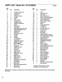
PART LIST--Model
Key
No.
Qty.
1
2
3
4
5*
6
7
8
9
10
11
12
13
14
15
16
17
1819
20
21
22
23
No. WLTL88060
R0696A
Description
Key
No.
Qty.
2
1
3
1
1
10
3
1
1
1
1
1
4
1
1
2
1
1
1
1
2
1
4
Handrail w/Foam Grip
Potentiometer
Cage Nut
Console Housing
Console
Screw
3/8" x 1" Bolt
6" Cable Loom
SAFEKEY_/Clip
Upright Pivot Washer
Choke
Motor Hood
Hood Screw
Reed Switch Extension Wire
Reed Switch/Sensor Wire
Adhesive Clip
Motor Belt
Speed Control Knob
Pot Wire
Upright
Wire Clip
12" Cable Loom
Hood Anchor
46
47
48
49
50
51
52
53
54
55
56
57
58
59
60
61
62
63
64
65
66
67
68
1
1
2
1
1
3
1
1
2
1
1
1
3
2
2
1
2
7
3
1
1
6
1
24
25
26
27
28
29
30
31
32
33
34
35
36
37
38
1
1
1
1
1
1
1
1
6
1
9
1
1
2
3
Upright Wire Harness
Safety Cover Plug
Circuit Breaker
3/8" x I 1/2" Washer
Clip Screw
Upright Pivot Bolt
Power Cord
Grommet
Anchor Screw
Safety Cover
Safety Cover Screw
Controller
Battery Cover
Incline Leg Nut
Incline Nut
69
70
71
72
73
74
75
76
77
78
79
80
81
82
83
1
1
2
2
1
2
1
2
1
1
2
1
2
1
2
39*
40
41
42
43
44
45
1
1
1
1
2
1
1
Motor/Pulley/Flywheel/Fan
Left Endcap
Allen Wrench
Rear Roller
Rear Roller Adjustment Bolt
Ground Wire
Right Endcap
84
#
#
#
1
12
1
1
Description
Frame
Motor Pivot Bolt
Foam Grip
Motor Tension Nut
Motor Tension Star Washer
Incline Leg Wheel Bolt
Motor Tension Bolt
Motor Tension Washer
Flange Nut
Motor
Pulley/Flywheel/Fan
4" Cable Tie
8" Cable Tie
Foot Rail w/Fastener
Front Leg Cap
Incline Leg
Belt Guide
Console Screw
Roller Adjustment Washer
Front Roller Adjustment Bolt
Front Roller/Pulley
Platform Screw
_._
Walking Belt w/Fastener
Upright/Motor Pivot Nut
Magnet
5/16" x 3" Bolt
Front Leg Washer
Walking Platform w/Fastener
Incline Leg Wheel
Safety Cover Clip
Ratchet Screw
Latch Screw
Incline Leg Spring
Incline Leg Spacer
Incline Leg Latch
Incline Leg Nut
Incline Leg Bracket
Incline Leg Bolt
Warning Decal
Fastener
8" White Wire, Male/Female
User's Manual
* Includes all parts shown in the box.
# Indicates a non-illustrated part.
Specifications are subject to change without notice. See the back cover for information about ordering replacement pads.
14
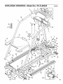
EXPLODED
DRAWING--Model
No. WLTL88060
3
4
\
\
\
\
48
Ro696A
\
63
\
1
\
\
7
63
57
63
48
\
7
14
12
6
3
15
:
19
69
26
71
66
69
35
;8
67
73
46
i
42
43
\
!
1
6
5O
40
I
i
41
59
47
51
79
15
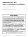
ORDERING REPLACEMENT
PARTS
To order replacement parts, call our Customer Service Department toll-free at 1-800-999-3756, Monday through
Friday, 6 a.m. until 6 p.m. Mountain Time (excluding holidays). When ordering parts, please be prepared to give
the following information:
• The MODEL NUMBER of the product (WLTL88060).
• The NAME of the product (WESLO CADENCE ®880 treadmill).
• The SERIAL NUMBER of the product (see the front cover of this manual).
• The KEY NUMBER of the part(s) (see page 14 of this manual).
• The DESCRIPTION of the part(s) (see page 14 of this manual).
If possible, place the treadmill near your telephone for easy reference when calling.
t
LIMITED WARRANTY
!
ICON Health & Fitness, Inc. ("ICON"), warrants this product to be free from defects in workmanshi p and
material, under normal use and service conditions, for a period of ninety (90) days from the dat__ of purchase. This warranty extends only to the original purchaser. ICON's obligation under this warranty is limited to replacing or repairing, at ICON's option, the product at one of its authorized service centers. All
products for which warranty claim is made must be received by ICON at one of its authorized service
centers with all freight and other transportation charges prepaid, accompanied by sufficient proof of purchase. All returns must be pre-authorized by ICON. This warranty does not extend to any product or
damage to a product caused by or attributable to freight damage, abuse, misuse, improper or abnormal
usage or repairs not provided by an ICON authorized service center, to products used for commercial or
rental purposes, or to products used as store display models. No other warranty beyond that specifically
set forth above is authorized by ICON.
ICON IS NOT RESPONSIBLE OR LIABLE FOR INDIRECT, SPECIAL OR CONSEQUENTIAL DAMAGES ARISING OUT OF OR IN CONNECTION WITH THE USE OR PERFORMANCE OF THE PRODUCT OR OTHER DAMAGES WITH RESPECT TO ANY ECONOMIC LOSS, LOSS OF PROPERTY,
LOSS OF REVENUES OR PROFITS, LOSS OF ENJOYMENT OR USE, COSTS OF REMOVAL,
INSTALLATION OR OTHER CONSEQUENTIAL DAMAGES OF WHATSOEVER NATURE. SOME
STATES DO NOT ALLOW THE EXCLUSION OR LIMITATION OF INCIDENTAL OR CONSEQUENTIAL DAMAGES. ACCORDINGLY, THE ABOVE LIMITATION MAY NOT APPLY TO YOU.
THE WARRANTY EXTENDED HEREUNDER IS IN LIEU OF ANY AND ALL OTHER WARRANTIES
AND ANY IMPLIED WARRANTIES OF MERCHANTABILITY OR FITNESS FOR A PARTICULAR PURPOSE IS LIMITED IN ITS SCOPE AND DURATION TO THE TERMS SET FORTH HEREIN. SOME
STATES DO NOT ALLOW LIMITATIONS
ON HOW LONG AN IMPLIED WARRANTY
LASTS.
ACCORDINGLY, THE ABOVE LIMITATION MAY NOT APPLY TO YOU.
This warranty gives you specific legal rights. You may also have other rights which vary from state to state.
ICON HEALTH & FITNESS, INC., 1500 S. 1000 W., LOGAN UT 84321-9813
Part No. 130734 F01671-C R0696A
Printed in USA © 1996 ICON Health & Fitness, inc.