1
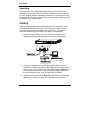
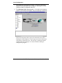
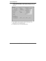
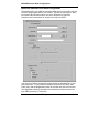
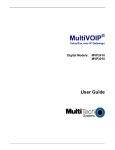
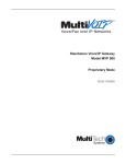
MVP100GK
Quick Start Guide
Quick Start Guide
MultiVOIP Gatekeeper MVP100GK
82010281, Revision B
This publication may not be reproduced, in whole or in part, without prior expressed
written permission from Multi-Tech Systems, Inc. All rights reserved.
Copyright © 2004, by Multi-Tech Systems, Inc.
Multi-Tech Systems, Inc. makes no representations or warranties with respect
to the contents hereof and specifically disclaims any implied warranties of
merchantability or fitness for any particular purpose. Furthermore, Multi-Tech
Systems, Inc. reserves the right to revise this publication and to make
changes from time to time in the content hereof without obligation of MultiTech Systems, Inc. to notify any person or organization of such revisions or
changes.
Record of Revisions
Revision
A
(07/05/04)
B
(09/20/04)
Description
Initial Release.
Updated software loading procedure.
Patents
This Product is covered by one or more of the following U.S. Patent Numbers:
5.301.274; 5.309.562; 5.355.365; 5.355.653; 5.452.289; 5.453.986. Other Patents
Pending.
Trademark
Trademark of Multi-Tech Systems, Inc. is the Multi-Tech logo. Windows and
NetMeeting are registered trademarks of Microsoft.
Multi-Tech Systems, Inc.
2205 Woodale Drive
Mounds View, Minnesota 55112
(763) 785-3500 or (800) 328-9717
U.S. Fax: 763-785-9874
Technical Support: (800) 972-2439
http://www.multitech.com
CONTENTS
Introduction ................................................................................................................4
Gatekeeper Basics.......................................................................................................4
Safety Warnings..........................................................................................................5
Lithium Battery Caution ...........................................................................................5
Safety Warnings Telecom.........................................................................................5
Safety Recommendations for Rack Installations ......................................................6
Gatekeeper Startup Tasks..........................................................................................7
Unpacking.................................................................................................................8
Cabling.........................................................................................................................8
Loading Gatekeeper Software .................................................................................10
Software installation is complete at this point. .......................................................14
Local Configuration..................................................................................................15
Pre-Requisites .........................................................................................................15
IP Parameters ..........................................................................................................15
Introduction
Introduction
Welcome to Multi-Tech’s new MultiVOIP™ Gatekeeper, Model MVP100GK, a
turnkey hardware and software solution that enables network managers and
intranet managers to define and control how H.323 voice traffic is managed
over IP networks. The Gatekeeper is a complementary product to the
MultiVOIP family. The Gatekeeper is an industry-standard mechanism for call
control and routing, basic telephony services, H.323 bandwidth usage control,
total network usage control, and overall system administration and security
policies. It includes fast, easy-to-use interfaces that network managers can
use to modify or update zone configurations when an individual on the
network needs additional services. And, it provides call centers with the
capability to perform needs-based call routing as well as providing a variety of
other automatic call distribution features.
Figure. Gatekeeper
Gatekeeper facilitates interoperability between PBX dial plans and IP-based
terminals. With it, call centers can route calls on the basis of need and
implement other automatic call distribution features, as well.
Gatekeeper Basics
Gatekeepers are optional within H.323 networks. However, when they are
present, gateways (voip units) and other network endpoint devices (like
terminals and Multipoint Control Units used in conferences) must use
Gatekeeper services. There are four functions that H.323 Gatekeepers must
provide to the network and many other functions, both standard and
proprietary, that the Gatekeeper may offer to network participants.
4
Multi-Tech Systems, Inc. Gatekeeper Quick Start Guide
Safety
Safety Warnings
Lithium Battery Caution
A lithium battery on the voice/fax channel board provides backup power for
the timekeeping capability. The battery has an estimated life expectancy of
ten years.
When the battery starts to weaken, the date and time may be incorrect. If the
battery fails, the board must be sent back to Multi-Tech Systems for battery
replacement.
Warning: There is danger of explosion if the battery is incorrectly replaced.
Safety Warnings Telecom
1. Never install telephone wiring during a lightning storm.
2. Never install a telephone jack in wet locations unless the jack is specifically
designed for wet locations.
3. This product is to be used with UL and cUL listed computers.
4. Never touch uninsulated telephone wires or terminals unless the telephone
line has been disconnected at the network interface.
5. Use caution when installing or modifying telephone lines.
6. Avoid using a telephone (other than a cordless type) during an electrical
storm. There may be a remote risk of electrical shock from lightning.
7. Do not use a telephone in the vicinity of a gas leak.
8. To reduce the risk of fire, use only 26 AWG or larger telecommunication
line cord.
Multi-Tech Systems, Inc. Gatekeeper Quick Start Guide
5
Safety
Safety Recommendations for Rack Installations
•
•
•
•
•
•
6
Ensure proper installation of the Gatekeeper in a closed or multi-unit
enclosure by following the recommended installation as defined by the
enclosure manufacturer. Do not place the Gatekeeper directly on top of
other equipment or place other equipment directly on top of the
Gatekeeper.
If installing the Gatekeeper in a closed or multi-unit enclosure, ensure
adequate airflow within the rack so that the maximum recommended
ambient temperature is not exceeded.
Ensure that the Gatekeeper is properly connected to earth ground via a
grounded power cord. If a power strip is used, ensure that the power strip
provides adequate grounding of the attached apparatus.
Ensure that the main supply circuit is capable of handling the load of the
Gatekeeper. Refer to the power label on the equipment for load
requirements.
Maximum ambient temperature for the Gatekeeper is 40 degrees Celsius
(104° F).
This equipment should only be installed by properly qualified service
personnel.
Connect like circuits. In other words, connect SELV (Secondary Extra
Low Voltage) circuits to SELV circuits and TN (Telecommunications
Network) circuits to TN circuits.
Multi-Tech Systems, Inc. Gatekeeper Quick Start Guide
Installation
Gatekeeper Startup Tasks
Task
Summary
● Collecting Phone/IP
Details ( vital! )
The Gatekeeper must be configured to
interface with your particular voip
network. To do so, certain details must
be known about each MultiVOIP that
uses the services of the Gatekeeper.
● Placement
Decide where you’ll mount the unit.
● Command/Control
Computer Setup:
Some modest minimum specifications
must be met. A COM port must be set
up.
Specs & Settings
● Hookup
Connect power, network, and
command port cables per diagram.
● Software Installation
This is the configuration program.
It’s a standard Windows software
installation.
● Phone/IP Starter
Configuration
You will enter phone numbers and IP
addresses. You’ll use default parameter
values where possible to get the system
running quickly.
● Phonebook Starter
Configuration
The phonebook is where you specify
how calls will be routed.
Multi-Tech Systems, Inc. Gatekeeper Quick Start Guide
7
Installation
Unpacking
Check the items on the Gatekeeper shipping list to ensure that you have
received the correct options and accessories. Unpack the unit and inspect it
for visible shipping damage. If damage is observed, do not power-on the unit;
contact Multi-Tech's Tech Support for advice. If no damage is observed, place
the Gatekeeper in its final location.
Cabling
Cabling your Gatekeeper entails making the proper connections for power,
command port, and Ethernet network. The below figure shows the back
panel connectors and the associated cable connections. The following
procedure details the steps necessary for cabling your Gatekeeper.
1.
Connect the power cord to a live AC outlet, then connect it to the
Gatekeeper’s power receptacle shown at top right in below figure.
2. Connect the Gatekeeper to the PC (the computer that will hold the
Gatekeeper software) using the RJ-45 to DB9 (female) cable provided
with your unit. Plug the RJ-45 end of the cable into the Command port
of the Gatekeeper and connect the other end (the DB9 connector) to
the PC serial port you are using (typically COM1 or COM2).
3. Connect a network cable to the Ethernet connector on the back of the
Gatekeeper. Connect the other end of the cable to your network.
8
Multi-Tech Systems, Inc. Gatekeeper Quick Start Guide
Installation
4. If you intend to configure the Gatekeeper remotely using the
Gatekeeper Windows GUI, connect an RJ-11 phone cable between the
Command Modem connector (at the rear of the Gatekeeper) and a
receptacle served by a telco POTS line. See below figure.
The Command Modem is built into the Gatekeeper unit. To configure the
Gatekeeper remotely using its Windows GUI, you must call into the
Gatekeeper’s Command Modem. Once a connection is made, the
configuration process is identical to local configuration with the Windows
GUI.
Figure. GND & Remote Config Modem Connections
5. Ensure that the unit is properly connected to earth ground by verifying
that it is reliably grounded when mounted within a rack.
This can be accomplished by connecting a grounding wire between the
chassis grounding screw (see above figure) and a metallic object that
will provide an electrical ground.
6. Turn on power to the Gatekeeper by setting the power switch on the
right side panel to the ON position. Wait for the Boot LED on the
Gatekeeper to go off before proceeding. This may take a couple of
minutes.
Proceed to Loading Gatekeeper Software section.
Multi-Tech Systems, Inc. Gatekeeper Quick Start Guide
9
Loading Software
Loading Gatekeeper Software
The software loading procedure does not present every screen or option in
the loading process. It is assumed that someone with a thorough knowledge
of Windows and the software loading process is performing the installation.
The MultiVOIP Gatekeeper software and User Guide are contained on the
Gatekeeper product CD. Because the CD is auto-detectable, it will start up
automatically when you insert it into your CD-ROM drive. When you have
finished loading your Gatekeeper software, you can view and print the User
Guide by clicking on the View Manuals icon.
1. Be sure that your Gatekeeper has been properly cabled and that the
power is turned on.
2. Insert the Gatekeeper CD into your CD-ROM drive. The CD should
start automatically. It may take 10 to 20 seconds for the MultiVOIP
Gatekeeper MVP100GK AutoRun screen to display.
If the AutoRun screen does not display automatically, click My
Computer, then right click the CD ROM drive icon, click Open, and
then click the Autorun icon.
3. When the AutoRun screen appears, click the Install Software icon.
10
Multi-Tech Systems, Inc. Gatekeeper Quick Start Guide
Loading Software
4. A ‘Thank you for choosing..’ screen appears.
Press Enter or click Next to continue.
5. Follow the on-screen instructions to install your Gatekeeper software.
The first screen asks you to choose the folder location of the files of the
Gatekeeper software.
Choose a location and click Next.
Multi-Tech Systems, Inc. Gatekeeper Quick Start Guide
11
Loading Software
6. At the next screen, you must select a program folder location for the
Gatekeeper software program icon.
Click Next. Transient progress screens will appear while files are being
copied.
12
Multi-Tech Systems, Inc. Gatekeeper Quick Start Guide
Loading Software
7. On the next screen you can select the COM port that the command PC
will use when communicating with the Gatekeeper unit.
8. A completion screen will appear.
Click Finish.
Multi-Tech Systems, Inc. Gatekeeper Quick Start Guide
13
Loading Software
When setup of the Gatekeeper software is complete, you will be prompted to
run the Gatekeeper software to configure the VOIP.
Software installation is complete at this point.
14
Multi-Tech Systems, Inc. Gatekeeper Quick Start Guide
Local Configuration
Local Configuration
This manual primarily describes local configuration with the Windows GUI.
After IP addresses have been set locally using the Windows GUI, most other
aspects of configuration can be handled through the web browser GUI. In
most aspects of configuration, the Windows GUI and web-browser GUI differ
only graphically, not functionally.
Pre-Requisites
To complete the configuration of
the Gatekeeper unit, you must
know several things about the
overall system.
Before configuring your Gatekeeper unit, you must know the values for IP
parameters that describe the IP network system.
IP Parameters
The following parameters must be known about the network (LAN, WAN,
Internet, etc.) to which the Gatekeeper will connect:
Ask your computer network
administrator.
#
Info needed to operate the
Gatekeeper.
IP Network Parameters:
Record for each VOIP Site
in System
• IP Address
• IP Mask
• Gateway
• Domain Name Server (DNS) Info
(not implemented; for future use)
Write down the values for these IP parameters in the above table.
Multi-Tech Systems, Inc. Gatekeeper Quick Start Guide
15
Local Configuration
1. Start Gatekeeper Configuration Program. Launch the Gatekeeper
program from the Windows Start | Programs | Gatekeeper x.xx-Gxx
(Version number) |Configuration and click.
2. The Gatekeeper main screen appears. If the main screen appears
grayed out and seems inaccessible, verify command port connection.
In the lower left corner of the screen, the connection status of the
Gatekeeper will be displayed. The messages in the lower left corner
will change as detection occurs. The message “Gatekeeper Found”
confirms that the Gatekeeper is in contact with the Gatekeeper
configuration program.
16
Multi-Tech Systems, Inc. Gatekeeper Quick Start Guide
Local Configuration
3. Set IP Parameters. This dialog box can be reached by pulldown menu
– (Configuration|IP), toolbar icon, keyboard shortcut, or sidebar.
In each field, enter the values that fit your particular network.
4. Diff Serv Parameters group’s values pertain to a differential
prioritizing system for IP packets as handled by Diff Serv-compatible
routers. The Call Control PHB (Per Hop Behavior) value prioritizes
call setup IP packets. The Voip Media PHB value prioritizes the
RTP/RTCP audio IP packets. Before changing these default values,
consult with a qualified IP telecommunications engineer or refer to the
TCP/IP standards described in the Gatekeeper Software Chapter 5,
Configuration IP Parameters section of the User Guide.
5. Enter the IP address of your network in the IP Address window.
6. Enter the IP Mask address for your network in the IP Mask window.
7. If a gateway device connects the Gatekeeper to the Internet, enter
the gateway’s IP address in the Gateway window.
Multi-Tech Systems, Inc. Gatekeeper Quick Start Guide
17
Local Configuration
8.
Change Gatekeeper Name. From the Main Gatekeeper screen, click
on Gatekeeper|Parameters and the Network Parameters screen is
displayed
9.
In the GK-ID window change the default Gatekeeper name MVP_SGK to your Gatekeeper name.
10. Click OK to save your new Gatekeeper name.
18
Multi-Tech Systems, Inc. Gatekeeper Quick Start Guide
MultiVOIP Phone Book Configuration
MultiVOIP Phone Book Configuration
The Phone Book Configuration screen for each MultiVOIP registering with the
Gatekeeper has to contain the Gatekeeper IP address, Gatekeeper Name,
and click on Register with Gatekeeper. A generic Phone Book Configuration
screen for a MVP410 and MVP 2410 is shown below.
The Gateway Name should have already been changed to the name for this
MultiVOIP. The generic Phone Book Configuration screen is shown for
example and field definition purposes only.
1. To open the Phone Book Configuration screen, click Phone
Book|Phone Book Configuration.
2. When you click the Register with Gatekeeper box, the Gatekeeper RAS
Parameters group becomes active.
3. Enter the IP address of your Gatekeeper in the Gatekeeper IP Address
window.
4. Enter your Gatekeeper Name in the Gatekeeper Name window.
5. Click OK to save your settings.
Multi-Tech Systems, Inc. Gatekeeper Quick Start Guide
19
MultiVOIP Phone Book Configuration
MultiVOIP Inbound Phone Book Configuration
Each MultiVOIP in your network requires at least one entry to receive a phone
call from another MultiVOIP in your network. Typically, a multiVOIP will have
two Inbound Phone Book entries; one set for access to its local PBX
extensions and a second set for access to its local area PSTN.
Your first set of entries will typically provide access to this MultiVOIP’s local
PBX extensions. You will need to consider the Remove Prefix entry, Add
Prefix entry, and the Registration Option at the lower left area of this screen.
The Registration Option that needs to be checked to provide access to the
local PBX extensions is Tech Prefix.
20
Multi-Tech Systems, Inc. Gatekeeper Quick Start Guide
MultiVOIP Phone Book Configuration
1. To open the Add/Edit Inbound Phone Book screen, click Phone
Book|Phone Book Modify|Inbound Phone Book|Add Entry.
2. Enter your remove prefix number in the Remove Prefix window to allow
access to this MultiVOIP’s local PBX extensions.
3. Enter your add prefix number in the Add Prefix window to allow access
to this MultiVOIP’s local PBX extensions.
4. If you want this MultiVOIP to allow any channel access to its PBX
extensions, leave the Channel Number option set for Hunting.
5. Enter a description (MultiVOIP’s location or site name, and possibly the
words PBX extensions) in the Description window. This will distinguish
this Inbound Phone Book.
6. In the Registration Options group at the bottom of the screen, click on
the Tech Prefix option.
7. Click OK when you have finished your entries in this Add/Edit Inbound
Phone Book screen.
Your second set of entries in the Inbound Phone Book will typically provide
access to this MultiVOIP’s local area PSTN. You will need to consider the
Remove Prefix entry, Add Prefix entry, and the Registration Option at the
lower left area of this screen. The Registration Option that needs to be
checked to provide access to the local area PSTN is H323 ID.
8. Enter your remove prefix number in the Remove Prefix window to allow
access to this MultiVOIP’s local area PSTN.
9. Enter your add prefix number in the Add Prefix window to allow access
to this MultiVOIP’s local area PSTN.
10. If you want this MultiVOIP to allow any channel access to its local
PSTN, leave the Channel Number option set for Hunting.
11. Enter a description (MultiVOIP’s location or site name, and possibly the
words Area PSTN) in the Description window. This will distinguish this
Inbound Phone Book.
12. In the Registration Options group at the bottom of the screen, click on
the H323 ID option.
13. Click OK when you have finished your entries in this Add/Edit Inbound
Phone Book screen.
Multi-Tech Systems, Inc. Gatekeeper Quick Start Guide
21
MultiVOIP Phone Book Configuration
MultiVOIP Outbound Phone Book Configuration
Each MultiVOIP in your network requires at least one outbound phone entry
to call another MultiVOIP in your network. Typically, a MultiVOIP will have two
Outbound Phone Book entries; one set to provide access to each locations
PBX extensions and a second set for access to each locations area PSTN.
22
Multi-Tech Systems, Inc. Gatekeeper Quick Start Guide
MultiVOIP Phone Book Configuration
Your first set of entries will typically allow access to a neighboring MultiVOIP’s
PBX extensions. This will allow your local phone users to dial out of the local
area to a neighboring MultiVOIP location. You need to consider the
Destination Pattern and Remove Prefix in the Phone Number Details group,
Description of this outbound phone book, and check Use Gatekeeper box and
enter your Gateway Prefix in the H.323 group.
1. To open the Add/Edit Outbound Phone Book screen, click Phone
Book|Phone Book Modify|Outbound Phone Book|Add Entry.
2. Enter your destination pattern value in the Destination Pattern window
to provide access to the neighboring MultiVOIP’s PBX extensions.
3. Enter your remove prefix value in the Remove Prefix window to
provide access to the neighboring MultiVOIP’s PBX extensions.
4. Enter a description (neighboring MultiVOIP’s location or site name,
and possibly the words PBX extension) in the Description window.
This will distinguish this Outbound Phone Book.
5. In the H.323 group, click on the Use Gatekeeper option box.
6. Enter your gateway prefix value in the Gateway Prefix window.
7. Click OK when you have finished your entries in this Add/Edit
Outbound Phone Book screen.
Your second set of entries will typically allow access to a neighboring
MultiVOIP’s PSTN. This will allow your local phone users to dial out of the
local area to a neighboring MultiVOIP location. You need to consider the
Destination Pattern in the Phone Number Details group, Description of this
outbound phone book, and check Use Gatekeeper box and enter your
Gateway H.323 ID in the H.323 group.
8. To open the second the Add/Edit Outbound Phone Book screen, click
Phone Book|Phone Book Modify|Outbound Phone Book|Add
Entry.
9. Enter your destination pattern value in the Destination Pattern window
to provide access to the neighboring MultiVOIP’s PSTN.
11. Enter a description (neighboring MultiVOIP’s location or site name,
and possibly the words PSTN) in the Description window. This will
distinguish this Outbound Phone Book.
12. In the H.323 group, click on the Use Gatekeeper option box.
13. Enter your Gateway H.323 ID value in the Gateway H.323 ID window.
14. Click OK when you have finished your entries in this Add/Edit
Outbound Phone Book screen.
Multi-Tech Systems, Inc. Gatekeeper Quick Start Guide
23
MultiVOIP Phone Book Configuration
Connectivity Test
When you have finished configuring your inbound and outbound phone books
for your VOIP network, verify that your gateways are registered with the
gatekeeper and then make a call to a VOIP in your network and verify that the
Gatekeeper is conducting the call correctly.
1. From the Gatekeeper main screen, click on GateKeeper|Endpoints
and verify that gateways are registered with the Gatekeeper.
2. From one of the gateways, dial another gateway in your network and
verify that the call connected. From the Gatekeeper main screen, click
GateKeeper|Calls and your call should be viewed in the Current
Calls screen.
Your Gatekeeper is operational.
24
Multi-Tech Systems, Inc. Gatekeeper Quick Start Guide
82010281