1
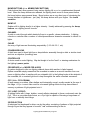
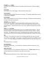
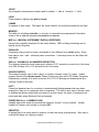
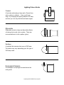
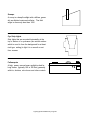
Lighting Systems Made Easy A Guide to Lighting Installations From corporate environments to houses of worship bring the beauty of the stage to any architectural application “Lighting Systems Made Easy” Page 1 Lighting Systems Made Easy Table of Contents Description Page Copyright Information ........................................................ 3 Preface ................................................................................ 4 Lighting: A Lot Like Sound ................................................ 5 A Few Simple Questions ................................................... 6 Where To Go To Purchase Your System ............ 6 Where Do You Need Lighting ............................... 6 What Is Your Budget .............................................. 6 How to Choose the Right Dimmer ....................... 6 What to Look for In A Lighting Console .............. 6 10 Points to Lighting Houses of Worship ....................... 7 Basic Lighting Scenario..................................................... 9 3 Point Lighting ....................................................... 9 Key and Fill Light .................................................... 9 Back Light ................................................................ 9 3 Point Lighting Drawing ................................................... 9 Seeing the Light ................................................................. 10 Power Requirements for Installations ............................. 11 Lighting Math ...................................................................... 12 3 Types of Installations ...................................................... 13 Small Portable System ...................................................... 13 Fixed Installation ................................................................ 14 Typical Permanent Installation Drawing ......................... 15 Fixed Installation Which Combination……… ................. 16 Architectural Control Panels ............................................. 17 Typical Quote for Installations .......................................... 18 Architectural Control Systems.......................................... 19 Leprecon® Lingo………………………………. ............... 20 Theatrical Vocabulary........................................................ 21 Glossary of Lighting Terms ............................................... 22 Photometric Data Chart..................................................... 29 DMX-512 Article-Your Guide to DMX-512 ...................... 30 Lighting Fixture Guide ....................................................... 35 Want To Learn More About Lighting? .............................. 37 Leprecon LLC 10087 Industrial Drive, P. O. Box 430, Hamburg, MI 48139-0430 810-231-9373, 810-231-1631, [email protected], www.leprecon.com “Lighting Systems Made Easy” Page 2 Copyright Information The contents of our electronic documents are copyrighted material. They are the property of CAE, Inc. and are provided as a service and or for instructional purposes only. Possession does not imply or convey rights to use many information herein, including photos, copy, illustrations, or art work or designs or concepts for any use except to promote products manufactured by CAE, Inc. (Littlite and Leprecon®). This information is proprietary and may relate to patents or patents pending that are the property of CAE, Inc. Use of the documents in complete and unedited form is granted to current distributors of Littlite or Leprecon® products. Use of portions, or edited versions of these documents is not allowed except by CAE’s authorization of each specific use. Please send proposed copy to CAE for approval. Trademark Protection The Littlite and Leprecon® trademarks and logo are the property of CAE, Inc. The words Littlite or Leprecon® must always appear with the circled R () registered trademark beside it. The contents of our documents are copyrighted material. They are the property of CAE, Inc. and are provided as a service and or for instructional purposes only. Possession does not imply or convey rights to use any information herein, including CAE has worked hard to establish and protect our logo, trademark and patents, which are widely known and associated with our patented & proprietary designs and our reputation for quality products and service. All dealers distributors and representatives of CAE, Inc. are required to properly use and protect our trademarks for our mutual benefit. “Lighting Systems Made Easy” Page 3 Preface A lot of people ask how lighting works in respect to audio and the answer is fairly simple: In audio you use a mixer to set the levels of your inputs and then send those levels to the amplifier (s). In lighting you have a control console which acts like a mixer and sends output information to the dimmer (s). Amplifiers power speakers. Dimmers power fixtures. Speakers output sound. Fixtures output light. The following page contains a diagram that further explains this relationship and will visually reinforce this theory. The important thing to remember is that there are three major parts to a lighting system: 1. Control Console 2. Dimmers 3. Fixtures 1. Control Console As stated above, a lighting console is a lot like a mixing console in the fact that you are setting levels for each channel. The difference on a lighting console is that the operator (often called lighting programmer or designer) is setting levels for a dimmer channel (which is wired to fixtures/lamps). You can think of a channel on a control console as a (dimmer) slide pot that allows you to run a group of lights from 0-100%. 2. Dimmers Dimmers are to lights what amplifiers are to sound. Power distribution devices that relay high voltage power. The major difference is that dimmers drive fixtures or lamps instead of speakers. The other reason we use dimmers is that a lamp that is set to a level less than 100% will generate noise (buzz). Dimmers use inductors, or chokes, to filter this noise. The bigger the inductor, or choke, the quieter the dimmer. 3. Fixtures Fixtures are wired to dimmer channels via different types of connectors. Some use plugs like U-Ground (Edison), Twist Locks or Stage Pins and others are hard wired using a terminal strip (primarily in installations). The PAR is the most popular fixture, however, we will discuss most fixtures in this manual. “Lighting Systems Made Easy” Page 4 Lighting A Lot Like Sound “Where a sound mixer controls the amplifier that drives the speaker, the lighting console controls the dimmer that drives the lamp”. Console........Dimmer........Fixture Mixer........Amp........Speaker Console................Automated Lights Mixer................Powered Speaker “Lighting Systems Made Easy” Page 5 A Few Simple Questions… Can Make Your Installation Go Smooth Where To Go To Purchase Your System • Call 1-888-4CAELEP for your nearest Leprecon dealer or sales representative. • Insist on quality Leprecon equipment, an effective design and flexibility in system integration. • Consult other churches for recommendations • Consult your area sales representative, architect, lighting designer, or professional contractor • Visit our website www.Leprecon.com for your area sales representative. Where Do You Need Lighting • The focus of the space-lectern or pulpit. • Areas of special interest: pulpit, choir loft, and baptismal areas. • Educational areas such as the youth hall or Sunday school rooms. • Emphasis on special architectural features such as icons, stained glass, seasonal features or organs. • Exit and aisle lighting. • Exterior lighting. • Emergency lighting • Leprecon’s architectural series can be designed to fit any application. What Is Your Budget • What is the focus of your space? Lighting can focus an audience’s attention better than any other feature. • How much did you spend on architecture? Lighting can accentuate your architecture and bring a recognizable return on your investment. • How much can you afford to spend on a lighting system? • Spend as much as you can afford. It will pay off in the long run. • Avoid lighting consoles that are difficult to operate • It is a waste to have a complex system that no one can operate. How Do You Choose The Right Dimmer • Choose a dimmer that has proven reliability. • The dimmer is the HEART and workhorse of your lighting system. • Is the dimmer 100% Duty Cycle? • The VX series dimmers can be operated at full-load continuously making them ideal for any installation. What To Look For In A Lighting Console • How many areas or functional zones will you be lighting? Do you need a channel or more for each area? • Who will be operating the console? • How many different looks will you need for any given performance? • Leave room for expansion. “Lighting Systems Made Easy” Page 6 10 Points To Lighting Houses of Worship ŒInstruments Should Not Be Obtrusive to the Sanctuary • Hide fixtures behind beams or paint them. • Most sanctuaries are designed as beautiful rooms and we aim to accent their beauty. •Pay Attention To The Angle Of Light • As with all lighting the angle of light should be cast at 30-50 degrees, 45 degrees being ideal. • Back lighting should be cast at 65 degrees. ŽLook For A User Friendly Console • Special attention should be paid to installing a console that is easy to use. • This will allow numerous people to operate the console. •Divide The Sanctuary Into Zones • When arranging a lighting plot, the sanctuary should be divided into zones, typically 3 to 6, leaving the stage area for theatrical fixtures. These “zones” will be controlled by architectural panels. •Set Up Various Lighting Plots • Be logical setting up zones. • Aisle, sconce, choir loft, the baptismal area, and so forth, could all qualify as their own zone. • Use the plot that accents the sanctuary best. ‘Don’t Forget A Walk Through • Architectural lighting should include a walk through (on/off)? Switch for any one entering the sanctuary during non-worship hours. • An access ”lockout” can be sued to deactivate any remote stations during the service. ’Lights Not Sound • Along with providing power to the lamps, the primary function of a dimmer pack is to keep the lamp filament from buzzing when the lights are not at 100% intensity. • Since Houses of Worship are quiet, a quality dimmer pack is often the key to a successful installation. “Lighting Systems Made Easy” Page 7 “To Gel Or Not To Gel • An often asked question…should gel or glass be used to filter the light and give it a “mood” (AKA color temperature)? • If the room has a high peak you may want to use glass because it will last longer. • If fixtures are accessible, or lighting will be called upon to change from week to week, gel would be the filter of choice. ”Schedule Maintenance • Scheduled maintenance should be performed regularly. • If the sanctuary has a high peak, you will want to change all the lamps and filters on a regular basis to avoid the need to rent a lift to change one or two lamps every few weeks. •2400 = 10 x 10 • Once you have divided the sanctuary into zones and have the determined the area you wish to light, you will need to figure out how many channels of dimming you will need. • Using the wattage of your lamps, you should be able to figure out how many channels of dimmers you will need. • Most dimmers come in 1.2kW or 2.4kW per channel. • One 2.4kW channel is usually enough to give a 10’ x 10’ area one look (or color temperature). • Example: 2 lamps x 1000 watts per channel for key and fill light and 1 x 300 watts for back light. “Lighting Systems Made Easy” Page 8 Basic Lighting Scenario 3 Point Lighting • Three point lighting is the ideal lighting scenario and includes hitting an object from 3 directions: two from the front and one from the back. Key and Fill Light • The two lights cast from the front are known as Key and Fill light and should be cast at a 45 degree angle. • The objective of Key and Fill Light is to give the object a full, natural look. Back Light • The third light is referred to as Back Light and is usually cast at a 65 degree angle. • Often overlooked, the objective of Back Lighting is to give the object a deep, 3 dimensional look… • Note: You should install Key and Fill lighting before you consider Back Lighting. 3 Point Lighting Shown Above “Lighting Systems Made Easy” Page 9 Seeing the Light’ If you have a 40' x 30' stage: 1. Divide into 10' x 10' squares 2. Count squares 3. Decide how many color looks per square 10 x 10 square = one look or a 2400 watt channel Example below is a stage area that is 30' x 40' 12 x 2400/ch = one look 24 x 2400/ch = two looks 36 x 2400/ch = three looks 40' 30' “Lighting Systems Made Easy” Page 10 Power Requirements for Theatrical or Architectural Lighting Installations Rack Size (Channel) Mains 3 Phase Power Requirement Mains Single Phase Power Requirement Max # of 600 Watt Fixtures Max # of 1000 Watt Fixtures 12 Channel x 2400 Watts Each 80 Amps per leg 120 Amps per leg 48 24 24 Channel x 2400 Watts Each 160 Amps per leg 240 Amps per leg 96 48 36 Channel x 2400 Watts Each 240 Amps per leg 360 Amps per leg 144 72 48 Channel x 2400 Watts Each 320 Amps per leg 480 Amps per leg 192 96 60 Channel x 2400 Watts Each 400 Amps per leg 600 Amps per leg 240 120 72 Channel x 2400 Watts Each 480 Amps per leg 720 Amps per leg 288 144 84 Channel x 2400 Watts Each 560 Amps per leg 840 Amps per leg 336 168 96 Channel x 2400 Watts Each 640 Amps per leg 960 Amps per leg 384 192 108 Channel x 2400 Watts Each 720 Amps per leg 1080 Amps per leg 432 216 120 Channel x 2400 Watts Each 800 Amps per leg 1200 Amps per leg 480 240 132 Channel x 2400 Watts Each 144 Channel x 2400 Watts Each 880 Amps per leg 960 Amps per leg 1320 Amps per leg 1440 Amps per leg 528 576 264 288 “Lighting Systems Made Easy” Page 11 Lighting Math 1000 Watt Par Bulb = 1000 Watts = 8.3 Amps 120 Volts 600 Watt Raylite Bulb = 600 Watts = 5 Amps 120 Volts For Example: If a customer wants to plug two 1000 watt lamps into a dimmer channel, the channel must be rated for a least 2000 watts or 20 amps. (In most installations, 2400 watts per channel are used with 2 each 1000 watt lamps per circuit or 4 each 575/600 watt lamps per circuit). “Lighting Systems Made Easy” Page 12 3 Types of Installations • Small portable system. • Fixed installation. • Fixed installation which combines Theatrical and Architectural Lighting Small Portable System • • Many Houses of Worship or small theatre groups venture outside of their venue to enlighten or perform. They many want to consider a portable system like the LP-612 memory console combined with LD-360 dimmers. LD-360-HP 6 Channel Dimmers Control Cable LP-612 Memory Console DMX or MPX Cable Control to Daisy Chain Packs Tree Mount Dimmer Features: MPX, DMX, or Analog 4 or 6 Channel Models Dual 20A SCR Power Devices Highly Reliable Power Modules Professional Quality Noise Filtering LP-612 Features: Two Scene Preset Mode Softpatch Chase Memory Bump Buttons with Add/Solo Mode Cue Stack and “GO” Button “Lighting Systems Made Easy” Page 13 Control Cable Features: DMX, Analog or MPX 50’ through 200’ Fixed Installation • • It is often the case that Architectural lighting already exists in the installation you are working on. If your installation calls for a theatrical style dimming and control, another option would be an LP-1600 Series console combined with a VX Permanent dimmer rack. VX 36 Channel Heavy Duty Permanent Dimming Rack 3 12 Channel VX-2400 Dimmer-TP/TL/RBK 1 Heavy Duty Free Standing Enclosure 1 Terminal Power Input-430A 1 DMX Control In/Out Dual 5 Pin XLR (M-F) 1 2RU Rack Mount Control In/Out Panel 1 2RU Rack Mount Blank Panel 19"W x 3.5"H 1 2RU Louvered Vent Panel 19" W x 3.5"H 1 4RU Rack Mount Blank Panel 19"W x 7"H 3 Wiring Harness 1 LP-1600 36/72 Plus NOTE: Leprecon LP-1600, LP-1500 or LP-600 series consoles have the ability to send (speak) DMX, and analog at the same time, making them ideal for systems that are being upgraded. This will allow the addition of dimmers, to supplement the existing dimming system, and can all be controlled from one console. “Lighting Systems Made Easy” Page 14 Typical Floor Rack Permanent Installation Drawing Multi cable 12 gauge 19 conductor UL Listed Junction Box with Terminal Strip Inside Connector Strip on truss punched for Stage Pins LP-1600 MEMORY CONSOLE “Lighting Systems Made Easy” Page 15 Fixed Installation Which Combines Theatrical and Architectural Lighting • If the entire lighting system needs to be replaced, or you are working on a new building, you may want to consider installing a combination of theatrical and architectural lighting, which would combine a theatrical system with remote architectural panels that are sprinkled throughout the room. Architectural control panel Architectural Control Panels are wall mount control panels that the playback of preset scenes with the touch of a button. You can think of it as a light switch in your home but rather than simply turning a light on and off, the switch would turn on numerous fixtures to a preset level, hence recalling a scene in a room is as easy turning a light on and off. You may have an installation and no floor space for a dimmer rack. What to do? Consider using the Leprecon® “LitescapeTM” architectural system. Leprecon’s Architectural System combines the unsurpassed reliability of Leprecon® dimming with their intuitive Leprecon® console design, allowing any architect, lighting designer, or design firm to “LitescapeTM” their environment. Designed to act as a stand alone unit or to interface a console and with Leprecon’s wall panel control stations, LitescapeTM will bring the beauty of the stage to any architectural application including themed environments, houses of worship, schools, and theaters. Triggering scenes from control consoles, wall panels, by the time of day, or advanced communication protocols allows users the freedom to choose their interface and create beautifully LitescapeTM environments. As with all Lepecon products, LitescapeTM is backed by Lepecons premiere service and 24 hours technical pager assistance. Following is a sample “LitescapeTM” architectural system which includes: Quote Specs Drawing • Always be sure to include code compliant emergency lighting in any public venue. • The following pages outline how you would design a Leprecon® system. “Lighting Systems Made Easy” Page 16 Architectural Control Panels Features Include: • Flexible Modular Design-Output Level LED Indicators • Up to 96 Total Zones-Keyswitch Priority Lockout • Supports 8 Rooms with 12 Presets Each-Programmable Presets 3P, 3F with Lockout and Off Shown Above 6P, 6F with Off Shown Above Preset Panel Stations are available in 1, 3, 6 and 12 buttons with off button. Preset stations are programmable using Litescape fader stations, Litescape wall dimmer scenes or DMX signal control. Light level for up to 12 zones can be assigned to any preset. Fader Panel-available in 1, 3, 6, 12 zone configurations with a master level fader on 3, 6, 12 zone models. All fader stations have an integral LED indicator within each fader. Lockout Station allows user (often in control booth) to lock out panels in remote locations (designated by low priority status) during a service or show. Dimmer Features Include: Convection Cooled, 100% Duty Cycle DMX-512 Programmable 100 Linkable Scenes Single Phase/Three Phase 96 Presets Up to 8 Rooms with 12 Zones Per Room LitescapeTM Dimmer “Lighting Systems Made Easy” Page 17 Typical Quote for installations which combine Architectural & Theatrical Dimming and Control 48 Channel Architectural & Theatrical Dimming and Control System 4 1 2 1 Litescape Architectural Series LWD-2400 12 Channel Dimmer Litescape Control Panel-6 Preset/6Fader w/Lockout & Master Litescape Control Panel-3 Preset w/Off LP-X24 Memory Console (DMX-512) This system allows 2400 watts per channel @48 channels of dimming and control. Includes remote panels which can be locked out in control booth via Lockout Station. LP-X24: 512 DMX channels w/integrated conventional-moving light control. Dimming=(4 LWD 2400 Wall Dimmers) 48 channels @ 2400 watts per channel Control=LP-X24 Console 512 DMX channels for integrated (dimming) and moving light control. Architectural: Includes remote panels which can be locked out via the Lockout Station Panel in Sound/Lighting Control Room. “Lighting Systems Made Easy” Page 18 Architectural Control Systems Walk Thru 1F Fader Panel Lighting & Sound Control Room 3F Fader Panel Leprecon Control Console and 6F and Access Control “Lighting Systems Made Easy” Page 19 Leprecon® “Lingo” Cue Stack (Cue List)- The ability to program scenes with individual fade times. The scenes can be played back with a manual crossfader or Go button. Delay Time- The wait time between steps in a cue stack. Hot-Patch- The ability to assign a live circuit to a dimmer channel. Typically done with a patch tail attached to a load connector. Point Cue- The ability to insert a cue within a cue. Great for editing shows after they have been programmed. Preset- Scene stored in memory for later use in a performance. Can be brought up with a Preset fader as well as “Add” or “Solo” bump buttons. Proportional Soft Patch- Allows patch level proportions to be entered for each dimmer channel. SCR- Abbreviation for Silicon Controlled Rectifier; solid state semiconductor device operating as a high speed switch and is the basis for most dimmers. Soft Patch- Allows user to assign multiple dimmer circuits to a single console channel. Wide Mode- The ability for a console to double its’ control channels. “Lighting Systems Made Easy” Page 20 Theatrical Vocabulary and Stage Layout Location Terms: House – Audience seating area. Apron – Area that surrounds front of stage. Proscenium – Arch over stage. Plaster Line – Imaginary line under proscenium. Upstage – Back of stage away from audience. Downstage – Front of stage towards audience. Stage Left and Right – Sides of stage from performer’s view. Note: Opposite audience view. On and Off Stage – In sight of audience and out of sight of audience (i.e., behind curtain). Front of House – Front seats in audience seating area. Electrics – Distribution of electricity. Batten – Pipe flown above stage. Line Set – Location of ropes that fly battens. Cyc Setting – Location of cyclorama. Booms – Pipes with instruments mounted on them, located on sides of stage. Balcony Rail – Front edge of balcony where instruments can be mounted. Wings – Extended areas on the left and right sides of a stage, in front on proscenium. Grid – Ceiling of stage area. Deck – Floor of stage. Flying Out and In – Flying out is raising batten and flying in is lowering batten. Equipment Terms: Dimmers and Control – Dimmers allow user to vary the intensity of lighting instruments. Control refers to a lighting console that outputs a signal to control a bank of dimmers. This allows an operator to individually control the intensity of each lighting instrument within an entire system. Fixtures – Lighting instruments. i.e., ellipsoidal, fresnel and PAR cans. Lamps – Light bulbs for lighting instruments. Grid Iron Junction Boxes – A/C junction boxes on battens, fed by conduit from dimmers. Connector Strips – Power distribution from junction boxes, fed by multi-pair cables. Plug-in Boxes – Housing with connectors for several circuits from dimmers. Floor Boxes – Floor mounted housing with connectors for several circuits from dimmers. Main Rag or Curtain – Primary curtain. Valance – Small curtains flown to hide electrics. Legs – Curtains on the sides of a stage that are hinged on vertical pipes in center of fabric. Scrim – Curtain that can be seen through, if objects behind it are backlit. Cyclorama – Upstage backdrop. Drop (two types) – Electric Drop – Where A/C power is dropped. Soft Goods Drop – Where scenery is dropped. Borders – Valances (small curtains that hide electrics). “Lighting Systems Made Easy” Page 21 Glossary of Lighting Terms A.C. Alternating Current in which the flow of electricity reverses polarity (+/-, +/-) a number of times a second. Normal U.S. power runs at 60 Hz., or reverses polarity 120 times a second, thereby making 60 complete cycles in this time. AMP The measurement used to describe the amount of electrical current flowing in a wire or circuit. Also the consumption of current by a lighting circuit. For lighting people, this term is most often found when circuit breakers are specified or when working out the power consumption of a lighting rig. Volts x Amps = Watts; therefore Amps = Watts/Volts. ARC An electric spark between two points. Used in very high output lights, such as xenon and mercury vapor lamps, and strobe tubes. (The bright light that you see from most flash cameras is a xenon arc.) A different type of arc also occurs in a badly made electrical joint – electrical joint arcing can heat up a power connection, destroy sensitive equipment and cause an electrical joint to fail. AUTO CHASE Lamps switched on/off in a sequence. The chase speed is set by a “pot” (or adjustable control), which provides manual up/down speed adjustment. A.W.G. Refers to the thickness of a wire, and determines its current carrying capability. The higher the AWG number the thinner the wire and the less current it will carry without heating up or burning out. BARN DOORS A number (normally two or four) or hinged flaps that are designed to selectively block off light from the front of a lighting instrument. Barn Doors are used to shape a beam of light, cutting the light off from selected areas. BLACKOUT A switch that, when pressed, will blackout the entire lightshow. Very useful when the operator wants to show projectors or strobes on their own, or feature UV lighting or pyrotechnics. Usually controlled by means of one button, or switch, on a lighting console. BREAKER Normal usage term for a Circuit Breaker. A device that trips out, cutting off the AC power when either too much current is drawn or when a complete short circuit occurs. For inductive loads, the breaker has to be of a higher rating than for resistive load because of the back-EMF generated by this type of electrical load. “Lighting Systems Made Easy” Page 22 BUMP BUTTONS (a.k.a. MOMENTARY BUTTONS) Push buttons that, when pressed, bring various lighting full on or to a predetermined dimmed level. When the bump buttons are released, the lighting levels revert to those preset before the bump buttons were pressed down. Bump buttons are a very direct way of introducing the human interface to lightshows – just “play” the bump buttons with your fingers. See touch sensitive. BUMP UP Sudden shift in lighting level(s) to a higher intensity. Usually achieved by pressing the bump buttons on a lighting control console. CHANNEL A path or control through which electricity flows to a specific, chosen destination. A lighting console or controller has a number of control/power/dimmer channels connected to control its lights. CHASE An array of light sources illuminating sequentially (1-2-3-4-4-3-2-1, etc). CONDENSER LENS A thick lens used to direct light from a lamp/reflector assembly through a slide or similar visual and into an objective (focussing) lens. CONTROLLER A device used to control lighting. May be thought of as the “brain” or steering mechanism for the lighting’s power packs. CROSSFADE (a.k.a. MIXER FOR AUDIO) A system designed to dim one lighting channel down while another is faded upward. Dipless crossfade simply means that the crossfade is made as a smooth transition from one scene or lighting effect to another with no noticeable ‘dip’ in the lighting levels at the midpoint of the crossfade, as a constant light level is kept throughout the entire crossfade movement. CYC. (Abbr. CYCLORAMA) A large screen on surface, often shallow and horizontally curved, usually erected at the rear of the stage. A Cyc. is most often used for color-wash lighting effects but may have slides of scenery or patterns of light projected onto it. CYC LIGHT (SCOOP) A lighting fixture with a large, shallow, curved reflector designed to throw a color-wash onto the Cyc. This is a very wide-angle fixture, so a Cyc Light is capable of throwing a large beam of light from a relatively short-range. 3D PROJECTION A technique first developed for disco use by the author consisting of patterns of light projected through fog so that they appear to be solid, “real” entities existing in the air. “Lighting Systems Made Easy” Page 23 D.C. Direct Current. Doesn’t change polarity. Much more dangerous than A.C. at the same voltage, as it will tend to grab onto and hold the recipient. A neglected, highly hazardous feature of most laser power supplies. (The laser beam is usually far less dangerous to life than the power supply.) DICHROIC A thin, rare earth coating often applied to a reflector to conduct heat backward and reflect light forward. Also used as a forward pass color filter of surpassing efficiency, capable of giving beautiful, almost monochromatic, colored light. DIM To lower the intensity of lighting. DIMMER PACK A device made to handle and adjust high power in response to control signals from a lighting console or controller. (See POWER PACK.) Used to keep lights quiet when run 100% below. DIODE A device that lets electricity flow through it one way only. Diodes are used in great numbers in all electronics. EMF (ELECTROMOTIVE FORCE) Back EMF usually occurs when an inductive component, such as a transformer, is switched on or off quickly. Because a coil (inductor) does not want to change electrical state quickly (reluctance), it “fights back,” creating a back EMF condition. This can cause problems with switch contacts (arcing) and circuit breakers. Neon transformers are a prime source of back EMF, and only specially made high-inductive load type dimmer packs should be used with them. FADER A device, usually a slide potentiometer, used to select various lighting levels. FLOOD Refers to either a wide light beam, the technique of flooding an area with light, or as an abbreviation for a floodlight. FLOODLIGHT A broad-beamed light source used to flood an area with light. FLY To suspend lighting, or other articles, up in the air by means of linkages secured to the ceiling. Strips of lights are commonly ‘flown’ above the front of the stage area. FOCUS Commonly used to denote the process of moving a lens back or forth, to produce a hard- or soft-edged light beam or a clearly defined image. Also used to refer to the center of activity or emphasis on a stage. “Lighting Systems Made Easy” Page 24 FOGGER (a.k.a. HAZER) A machine used to generate volumes of fog within a given environment. Enhances lighting effects. FOG JUICE Liquid supplied for use with foggers. Often perfumed in many scents. FOLLOW SPOT A large and powerful spotlight that has its own operator. The spotlight’s beam follows a person to keep him/her highlighted. FOOTLIGHTS Strips of lights provided at floor level at the front of the stage. Footlights are inclined upward at an angle to illuminate the performers. FRESNEL (Pron.: FRA-NEL) A flat lens that, by a pattern of annular rings, achieves similar properties to that of a planconvex lens. Fresnels are normally used to produce softer-edged beams than plano-convex equipped devices. The term fresnel is also used to refer to lighting instruments that use these lenses. GOBO (a.k.a. PATTERN) A flat piece of patterned material placed in the front of a theatrical lantern/projector. The pattern takes the form of holes punched through the metal, thereby forming a screen or stencil type effect. The images formed are often very elaborate and are commonly of trees or other outdoor scenes, as this can be an inexpensive and highly portable way of dealing with scenery. GEL A light filter. Gel originally got its name from the theatrical light filters that used to be made from sheets of colored gelatin. Today’s gel is a very different material and is available in a host of colors. Gel shade swatches are available via theatrical dealers (they give them away free). I.C. An Integrated Circuit or microchip. INCANDESCENT Any ordinary filament lamp. If not powered by a transformer (inductive component), it is a resistive load. INDUCTIVE LOAD Contains a winding or coil (e.g. transformer, electric motor, etc.). Dimmer packs have to be specially designed and manufactured to cope with inductive loads. IRIS A mechanical device that adjusts a beam of light to become a larger or smaller circle. “Lighting Systems Made Easy” Page 25 JOULE An energy/time measurement usually used for strobes. 1 watt at 1 second = 1 Joule. LOAD Power drawn by lighting (see watt and amp) LUMEN A measure of light output. The higher the lumen number, the more light emitted by the lamp. MEMORY The ability for a lighting controller, or console, to remember pre-programmed information. Used to call up operator-programmed presets and scenes. MIDI (acr.: MUSICAL INSTRUMENT DIGITAL INTERFACE) Having been originally developed for the music industry. MIDI is finding increasing use for lighting control purposes. PARALLEL Companion wiring mode for lamps, comparable to (but different from) series wiring. Every lamp has its own + and – electrical power connections. If one lamp burns out the others will stay alight. PAR (acr.: PARABOLIC ALUMINIZED REFLECTOR) The number indicated the size measured in pitches of 1/8” across the curved front of the lamp, so a PAR 38 lamp is 38 x 1/8” across the front of the lamp. PHASE CONTROL The method normally used to dim a lamp, or number of lamps, using A.C. power. Unless properly filtered at the dimmer packs, Phase Control may give rise to RFI (Radio Frequency Interference), normally at its worst at around 25 to 70% of dimming and characterized by a “buzzing” heard in the audio. PLOT Primarily a theatrical term for a number of predetermined lighting scenes that have been arranged so they run in a particular order or sequence. The term is also used to denote a plan or drawing that shows where lights are placed in a given venue, the types of instruments selected and their wiring (Electrical Plot) and quantity. POWER PACK (a.k.a. DIMMER PACK) Handles high power loads and provides the electrical “muscle” for the controller. Usually installed in a power room remote to minimize RFI. PRESET(S) A lighting term for a scene stored in memory for later use during a performance. Also used to connote the faders on a lighting console. “Lighting Systems Made Easy” Page 26 PYRO (Abbr. PYRO TECHNICS) Fireworks are often remotely fired by electricity. “Pyro shooting” may require a state-licensed operator. Can be dangerous – use with extreme care and caution. QUARTZ HALOGEN An incandescent lamp that has a quartz envelope and a halogen gas inside it. These lamps usually exhibit a higher color temperature (whiter light) and a longer operating life, as they are more efficient than an ordinary lamp. Halogen lamps must not be touched by the human skin (fingers etc.) or contaminated by grease or oil, as this will cause them to blacken prematurely. RELAY An old-fashioned (but economical) mechanical device that allows a small signal to control a high-powered electrical load. A basic relay consists of a solenoid, which, when energized, acts as an Electromagnet to pull a number of electrical contacts together. Good when used to control particular types of electric motors that should not have dimmer packs associated with them. A source of RFI if not properly suppressed. RFI Acronym for Radio Frequency Interference RIG A collection of lighting instruments and other equipment usually held together by means of some kind of metal truss. SCENE A number of lighting instruments, or displays, united together in various combinations at different dimming levels to provide a specific lighting effect SCR (acr.: SILICON CONTROLLED RECTIFIER) A solid-state electrical device usually used for dimming (phase control) purposes. Two SCRs are often used in back-to-back configuration for theatrical lighting control/dimming. SHORT Electrical jargon for Short Circuit. A short is often caused by accidental electrical insulation breakdown. This is when the circuit breaker operates, protecting your valuable equipment and saving the wiring from burning out. SIGNAL (See Control Logic Voltage) SOUND CHASE (a.k.a. AUDIO CHASE) Same as auto chase, but the switching of the lighting sequence is controlled by the music’s rhythm or beat (bass, drums, etc.) so the lighting sequence responds to the beat of the music. SOUND TO LIGHT Sound is split into a number of frequency bands by filters, and different lighting channels are switched on according to the amount of bass, middle, mid-hi and high sound frequencies that are presented at the controller’s sound input. “Lighting Systems Made Easy” Page 27 SOURCE (LIGHT SOURCE) A point of origin from which light is emitted. Also a device that generates light. A halogen lamp and a laser are both light sources. SPOTLIGHT An intense, narrow-angle light beam, or a commonly used term for a lighting instrument capable of producing such a beam. STRIP LIGHT A strip of lighting often “flown” at an inclined angle above the front of the stage. May also be found arranged in rows above the stage ceiling. STROBE (Abbr. STROBOSCOPE) Flickering light that visually freezes motion. A higher-powered stage version of the original engineering instrument developed to study moving parts while they are in motion. TOUCH SENSITIVE Control keypads that respond instantly to the touch of a finger. TRANSFORMER Device used to change the A.C. input voltage to high or low output voltage. Because it uses wound coils, it is an inductive load and dimmer packs should be selected with this in mind. TRUSSING A structure, usually tubular in construction, typically used to suspend lighting, speakers, etc. Modern Trussing is modular, made of lightweight aluminum, and comes with prefabricated corners and straight sections in order that it may be put together quickly. TRIAC A solid state A.C. switch mostly used for heavy power handling and dimming of lighting. VOLT Describes the amount of electrical potential available from a power source. WATT The most commonly used unit of electrical power. AMPS X VOLTS = WATTS. It therefore follows that WATTS/VOLTS = AMPS. YOUR GUIDE TO DMX-512: AN OVERVIEW PROFESSIONAL LIGHTING MAGAZINE BY BRAD DICKSON “Lighting Systems Made Easy” Page 28 PHOTOMETRIC DATA CHART Instruments Wattage Image Size at 30’ Par 64 Wide (WFL) 1000W 500W 13’ x 26’ Par 64 Medium (MFL) 1000W 500W 8’ x 16’ Par 64 Narrow (NSP) 1000W 500W 3.5’ x 7’ Par 64 Very Narrow (VNSP) 1000W 500W 3.2’ x 6.5’ Altman 360Q Leko 6” x 9” 1000W 750W & 500W 20’ Altman 360Q Leko 6” x 12” 1000W 750W & 500W 14’ Altman 360Q Leko 6” x 16” 1000W 750W & 500W 10’ Altman 360Q Leko 6” x 22” 1000W 750W & 500W 6’ These are images at 30’. For image size at 15’, just divide image size by 2. For image size at 10’, just divide image size by 3. “Lighting Systems Made Easy” Page 29 Current lighting designs have expanded to include a lighting control network design. Although instrument selection colour selection, lamp placement dominate the design process, the lighting control system also requires careful planning. Lighting consoles control dimmers and a wide range of automated devices. Control communication must be standardized if equipment from different manufacturers is expected to operate within a network, controlled by a lighting console. The lighting industry has adopted DMX-512 as their standard control protocol. Understanding DMX-512 is vital for anyone involved in the design or installation of lighting systems. Although the adoption of a standardized control protocol is accepted by today’s manufacturers this was not always the case. Prior to adopting DMX-512 as a control standard, manufacturers used their own propriety control signals. This meant Manufacturer “A’s” lighting board would only work with manufacturer “A’s” dimmers. The lighting industry became frustrated with the lack of compatibility between different dimmers and control console manufacturers. Manufacturers adopted the DMX-512 control protocol, as the control “language” lighting consoles would use to “talk” to their dimmers to appease the lighting industry. The development of DMX-512 was based simply upon the control of dimmers by a lighting console. The original developers did not envision the wide range of devices that DMX-512 would be controlling today. Although adequate to meet the demands of dimmer control the DMX-512 protocol is often pushed beyond its original expectations by automated lighting systems. However DMX-512 still remains the common protocol widely used in today’s entertainment lighting industry. DMX-512 is multiplexed digital lighting control protocol with a signal to control 512 devices. The term device is used because today’s lighting consoles could control scrollers, non-dim relays, moving lights, a graphical light in a computerized virtual reality set or dimmers. DMX-512 comprises digital signal codes (zero or one). When a transmitting device (e.g., lighting console) sends its digital codes, the receiving device (e.g., dimmer) transforms these codes into a function command (e.g., dimming to the specified level). With digital systems, signal integrity is compromised less over long cable runs, compared with analog control. When a 0/1 digit is sent and received as a 0/1 digit, the device will perform the desired task. The signal is transmitted on two wires twisted together, referred to as twisted pair. The connectors used are 5 pin XLR, although the current DMX standard only uses pins 1, 2 and 3. Pin 1 is the signal common shield, pin 2 is data – and pin 3 is data +. The signal is comprised of a voltage rise, between 0 and 5 volts, carried on the twisted cables. The DMX transmitter creates a rise of voltage on one cable, at a specific timing, while there is not voltage rise on the opposite cable at the exact same time. The receiver looks at the two incoming signals on pins 2 and 3 then compares the differences. A voltage rise on one wire and the inverse on the other will be seen as a differential and therefore deciphered as a digit. When both signals are identical (having an identical voltage rise on both cables at the identical time) no difference is recognized and no digit deciphered. If interference were accidentally transmitted alone the line, it would impart no response as long as the interference was identical on both lines. The proximity of the two cables assists in distributing interference identically on both wires. The signal driver, within the lighting console, transmits 512 device codes in a continual, repetitive stream of data. To obtain control of devices beyond 512, additional outlet ports are added to the console. The added ports will operate in multiples of 512, port 1 will control devices 1 through 512, port 2 controls devices 513 through 1024, etc. The receiving device is addressed with a number between 1 and 512 so it will respond only to data that corresponds to its assigned “Lighting Systems Made Easy” Page 30 address. Devices with identical addresses, from the same DMX outlet, will respond identically. To achieve individual responses the devices must have an individual address. Imagine a room filled with 512 people if they are all named “Bob” they would all stand up if you instructed “Bob, please stand up”. If each individual had a distinct name you could instruct each person to perform your commands simply by calling them by each unique name. This analogy applies to DMX addressing of devices along a DMX line. Attention to specific procedures and the correct cable type is important when transmitting DMX-512. Failure in the DMX network can often be traced to poor installation practices. Use cable designed to EIS RS-422/485 specification to carry a DMX signal. Connect devices in a sequential order like a chain linking one unit to the next, starting from the console. A maximum of 32 receiving devices per DMX line is recommended. Single DMX cable runs should not exceed 4,000 feet. Install a terminator (resistor) at the end of the DMX line of devices. This will reduce the possibility of signal reflection, which can create errors in the DMX signal. The cable type used will determine the ohm value of the resistor. Some devices allow for selftermination at the end of the line. Distribute multiple lines of DMX data through an opto-repeater. This device creates a physical break in the line by transforming the electrical signal into light, which spans a gap, and then it is restored to electrical signals. This function is performed by opto-isolators (optically isolating the electrical signal) within the repeater. This protects devices from damaging high voltage, accidentally travelling along the network. It will also repeat the original DMX data to several output lines. The input data is recreated at the outputs, eliminating distortion. The signal leaves the opto-repeater as strong as it left the console. Using a “Y” cord (two DMX output cables to a single input connector) degrades the DMX signal and should be avoided. A simple DMX network would begin with the lighting console, the DMX 5-pin XLR output of the console is connected to a cable designed to EIA RS-422/485 specification to carry a DMX signal. If the signal were to be transmitted to multiple locations then the next in-line device would be an opto-repeater, to protect and distribute the signal. Even when the signal is directed along a single path the use of an opto-isolating device is a beneficial protective practice. The signal continues along another cable, designed to EIA RS-422/485 specification to carry a DMX signal, from the output of the opto-repeater to the first device you wish to control with the lighting console. The device should be addressed with a numeric value between 1 and 512, to decipher the corresponding numeric DMX data transmitted by the lighting console. Each device is connected one after the other, using the input and output XLR connectors, similar to a chain. The last device, on each line, should use a terminator (resistor) on the output XLR to keep signal integrity. Following these simple practices should insure a DMX network that operates correctly. When there is failure within the network tracing the fault can be time consuming, test equipment now exists to aid in network checking. They range from units that can generate DMX, receive DMX to simple plug-ins that illuminate and LED when it receives voltage on pins 2 or 3. Many manufacturers recognize the importance of visual assurance the device is receiving a signal. Many devices now include an LED that illuminates when receiving the DMX signal. Along with a visual inspection, the individual cable continuity should be tested. Pins 1, 2 and 3 of the DMX cable should be checked. Although the DMX standard is 5-pin XLR, the cable itself “Lighting Systems Made Easy” Page 31 may only contain the minimum 3 cables required to carry the DMX signal. In this instance you will not get continuity when checking between pins 4 and 5. The DMX specifications currently do not define a function for pins 4 and 5 but some manufacturers use these pins to transmit read back information from a device. If a device at the end of the DMX line functions as desired, this is a good indication the signal is being transmitted correctly. When failure occurs at the end of the line, backtrack along the line to the first device functioning correctly. Place a test unit, which can receive the DMX signal, on the output of this device, this will determine the beginning of the failure. Test units that receive the DMX signal and displays a readout of the signal in a percentage value, are beneficial to confirm changes from the lighting console are received along the line. Individual devices can be tested, without a connection to a lighting console, with DMX transmitting test units. These test units are compact and portable, making it easy to check the system at any location of the network. An error occurring in the middle of a line often indicates signal reflection, a distortion of the DMX signal. A distorted DMX signal can cause the receiving device to trigger unexpectedly. Signal reflection can be compared to an echo effect, the signal is transmitted to the end device then bounces back up and down the line. A terminating resistor at the end of each DMX line will eliminate signal reflection. DMX networks can be limited, a single lighting console connected to an opto-repeater that sends the signal to the dimmers and scrollers. They can also be expansive like the DMX network installed at the Canadian Broadcasting Corporation Studio 42 in Toronto. The CBC designed this system for a wide variety of applications. This network offers the ability to connect lighting consoles scrollers and automated lights into a prewired network and then route their control via computer to an electronic DMX patching panel. The heart of the CBC system is a computer controlled DMX network patch panel that allows multiple input DMX signals to be distributed to specific DMX outlets in the studio. The computer software allows patch configurations to be saved and recalled when needed. This system offers many diverse configurations. Beginning from the lighting console, or multiple lighting consoles, the DMX patch operator decides the control route for the specific console dependent upon the location of the controlled device with the studio. As an example let’s take three devices and follow their path. First we can assign dimmer control to the desired lighting console, again dimmers are controlled in blocks of 512, so we could have separate consoles controlling separate 512 blocks of dimmers. Dimmer control of the same block of 512 can be shared between two consoles with the aid of a DMX merge box. A DMX merge box combines both input DMX signals into a single DMX output. Devices will respond to the input console that has the highest output level, so if device 194 is set to 50% on one console and 70% on the second console device 194 will respond to the 70% level. It is also possible to cross DMX ports and assign individual devices to the specific lighting console with a separate electronic DMX patch unit. The benefit of this complete system is evident when the DMX output control from an automated lighting console is mixed with a conventional lighting console output to control specific dimmers within the same 512 data stream. This of course eliminates the need for a separate dimmer system for automated lights requiring external dimming. Along with the standard “Lighting Systems Made Easy” Page 32 dimmer outlets in the studio, multiple DMX outlets are distributed conveniently in the studio. The outlets are set up to be DMX output or input because they have both a male and female 5-pin XLR connectors on the same line. The outlets are an either or situation, if it is used for output you cannot plug into the input and transmit DMX along the same line. Even this rule does not always apply, if you make a special adapter it is possible to utilize the 4th and 5th cable, that is not used according to DMX specifications, to transmit DMX on the same line. This practice must be closely monitored to insure to DMX input does not inadvertently get connected to the DMX output signal. Experience is the best teacher and the skilled crew at CBC has been using this system for several years. The second device we will follow is a scroller. The scroller’s DMX input is connected to the DMX output closest to the scroller. The DMX operator then chooses the DMX control source and assigns the numbered DMX output that will control the scroller. The information is sent to the DMX patch rack via computer and the specific input and output cables are electronically connected. The DMX patch rack verifies the information transferred, via computer, and then sends a response to the computer acknowledging the information. Automated devices like scrollers often require an external non-dim power supply to operate. Non-dim power supply to operate. Non-dim power is supplied next to every DMX outlet in the studio. Studio 42 has DMX controlled relays to turn the non-dim power individually on and off. All of the relays have individual DMX addresses so they can be individually controlled by the lighting console. The system also allows control signals other than DMX to be transmitted along the DMX cable. When connecting an alternate control protocol the outlet is deselected from the DMX patch rack making it possible to physically input the control protocol to one of the inputs on the rack. With this flexibility an automated light that operates on its own protocol can be powered by the non-dim power supply then plugged into the DMX outlet. The control signal is sent to the rack then physically distributed, with jumper cables, to the specific outlets connected to the automated light. Many automated consoles incorporate DMX output to control peripheral equipment while simultaneously transmitting an alternate control signal to the automated lights. The DMX output can be used to power the DMX non-dim relays on and off making all the control originating from the same lighting console. The Studio 42 DMX network is one example of an efficiently operating DMX network installation. Advances in DMX distributions have spawned current devices on the market that allow DMX to be sent without wires. Radio DMX is available from several manufacturers. The techniques used vary between manufacturers but the result is wireless DMX. Transmitters are connected to the DMX output from the console and the receiver is connected to the DMX device to be controlled. Cable distribution could be an economical alternate from the receiver rather than multiple receivers at every DMX device. Radio DMX makes it possible to control devices where cable distribution is impractical. For example multiple self-powered lighting rigs on a parade float could be controlled from a distant lighting console. DMX-512 is the common ground for all manufacturers in the lighting industry. As I have briefly outlined this control protocol requires attention to some basic operation techniques. Adherence to these techniques, when designing and implementing a DMX network will insure your DMX devices will operate to their maximum potential. Brad Dickson is the Lighting Director/Lighting Instructor at the Canadian Broadcasting Corporation in Toronto, with over 20 years experience at CBC Lighting. He is an Executive Board Member of the Society of Television Lighting Directors, webmaster of the STLD website and a member of SMPTE. “Lighting Systems Made Easy” Page 33 “Lighting Systems Made Easy” Page 34 Lighting Fixture Guide Fresnel A luminaire embodying a lamp and a Fresnel lens, with or without a reflector. It has a soft beam edge. By changing the spacing between the lamp and lens you can vary the field and beam angles. Ellipsoidals Ellipsoidals contain a lamp an ellipsoidal reflector, a framing device and a lens system. There are accommodations to hold a pattern (gobo). Par Cans A spotlight like luminaire that uses a PAR lamp. The beams may vary depending upon the type of PAR lamp used. Borderlights/Striplights A borderlight is a strip light mounted above the acting area. “Lighting Systems Made Easy” Page 35 Scoops A scoop is a deep floodlight with a diffuse, generally an elliptical contoured reflector. The field angle is commonly less than 1000 Cyc Strip Lights Strip lights that are mounted horizontally at the top or bottom of a cyclorama (the vertical surface which is used to form the background for a theatrical type setting) to light it in a smooth or uniform manner Followspots A high power, narrow beam spotlight suited for long throws (typically 100 to 300 feet) generally with iris, shutters, color boom and other controls. “Lighting Systems Made Easy” Page 36 Want To Learn More About Lighting? There are many sources to learn more about lighting, including: Lighting Dimensions New York NY 10011-4612 212-229-2965 FAX 212-229-2084 Entertainment Design 32 West 18th Street New York NY 10011-4612 212-229-2965 FAX 212-229-2084 United States Institute of Theatre Technology 6443 Riding Road Syracuse, NY 13206-1111 315-463-6463 FAX 315-463-6525 EM Bookshelf 6400 Hollis St. #12 Emeryville CA 94608 800-233-9604 International MIDI Association 5316 W. 57th Street Los Angeles, CA 90056 213-649-6434 FAX 213-215-3380 Digital ARTS and Technologies 21 Glen Ridge Road Mahopac NY 10541 914-628-7949 FAX 914-628-7941 ESTA Protocol 875 Sixth Avenue, Suite 2302 New York, NY 10001 212-224-1505 FAX m212-244-1502 Technologies for Worship Magazine P.O. Box 35, 20Wellingston St. East Aurora, ON, Canada L4G 3HI 905-830-4300 FAX 905-853-5096 Professional Lighting Magazine 23 Hannover Dr., #7 St. Catharines, ON, Canada L2W 1A3 905-641-3471 FAX 905-641-1648 “Lighting Systems Made Easy” Page 37