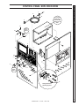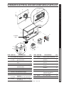
1
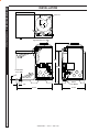
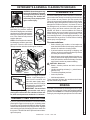
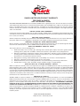
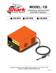
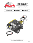
HNG
OPERATOR’S MANUAL
■ HNG-4020
■ HNG-3530
■ HNG-5030
For technical assistance or the SHARK dealer nearest you,
visit our website at www.shark-pw.com
97-610
CONTENTS
Introduction & Important Safety Information
5-6
Component Identification
7
Installation
8
Installation Guide
9-12
Check List Before Starting
12
Assembly Instructions
13
Operating Instructions
14
Detergents & General Cleaning Techniques
15
Shut-Down & Cleanup
16
Storage
16
Basic Facts
17
Troubleshooting
18-19
Maintenance & Service
20-23
Heating Coils
20
Propane Gas
21
Burner Features
21-22
Burner Troubleshooting
22-23
Preventative Maintenance Schedule & Oil Change Record
24
Hose & Spray Gun Assembly
25
Exploded View, Left Side
26
Exploded View, Right Side
27
Exploded View, Parts List
28-29
Float Tank Assembly
30
Burner Assembly, Exploded View
31
Burner Assembly, Exploded View, Parts List
32
Control Panel
33
Control Panel, Parts List
34
Electrical Box, Standard, Parts List
35
Electrical Box, Time Delay
36
3
SHARK HNG • 97-610 • REV. 1/05
CONTENTS
Electrical Box, Time Delay, Parts List
37
Electrical Box, Auto Start
38
Electrical Box, Auto Start, Parts List
39
Specifications
40-41
Warranty
Model Number ______________________________
Serial Number ______________________________
Date of Purchase ____________________________
The model and serial numbers will be found on a decal attached to
the pressure washer. You should record both serial number and
date of purchase and keep in a safe place for future reference.
4
SHARK HNG • 97-610 • REV. 1/05
Thank you for purchasing our Pressure Washer.
This manual covers the operation and maintenance of
the 301007D, 352007A, 402007A, 402007B, 402007C,
502007A, 502007B, 502007C, 353007A, 353007B,
353007C, 503007B and 503007C model washers. All
information in this manual is based on the latest product information available at the time of printing.
We reserve the right to make changes at any time without incurring any obligation.
3. Know how to stop the machine and bleed pressures quickly. Be thoroughly familiar with the controls.
4. Stay alert. Watch what you are doing.
WARNING
Owner/User Responsibility:
The owner and/or user must have an understanding of
the manufacturer’s operating instructions and warnings
before using this pressure washer. Warning information
should be emphasized and understood. If the operator
is not fluent in English, the manufacturer’s instructions
and warnings shall be read to and discussed with the
operator in the operator’s native language by the purchaser/owner, making sure that the operator comprehends its contents.
Owner and/or user must study and maintain for future
reference the manufacturers’ instructions
This manual should be considered a permanent
part of the machine and should remain with it if
machine is resold.
When ordering parts, please specify model and
serial number.
RISK OF EXPLOSION:
DO NOT SPRAY
FLAMMABLE
LIQUIDS.
WARNING
WARNING: Flammable liquids
can create fumes which can ignite causing property damage or
severe injury.
5. Risk of explosion - Do not
spray flammable liquids or operate in an explosive location.
Operate only where open
flame or torch is permitted.
WARNING: Keep water spray
away from electrical wiring or fatal electric shock may result.
Read warning tag on electrical
cord.
6. To protect the operator from
electrical shock, the machine
KEEP WATER SPRAY
AWAY FROM
must be electrically grounded.
ELECTRICAL WIRING.
It is the responsibility of the
owner to connect this
machine to a UL grounded receptacle of proper voltage and amperage ratings. Do not spray water on
or near electrical components. Do not touch machine with wet hands or while standing in water.
Always disconnect power before servicing.
IMPORTANT SAFETY
INFORMATION
WARNING: Spray gun kicks back. Hold with both
hands.
WARNING: When using this machine basic precautions should always be followed, including the following:
7. Grip cleaning wand securely with both hands before starting the cleaner. Failure to do this could
result in injury from a whipping wand.
CAUTION
CAUTION: To reduce the risk of
injury, read operating instructions carefully before using.
1. Read the owner's manual
thoroughly. Failure to follow instructions could cause malfunction of the machine and
READ OPERATOR’S
MANUAL
result in death, serious bodily
THOROUGHLY
injury and/or property damPRIOR TO USE.
age.
2. All installations must comply with local codes. Contact your electrician, plumber, utility company or
the selling distributor for specific details.
OPERATOR’S MANUAL
This machine was designed for
maximum use of 4 hours per day,
5 days per week.
To comply with the National Electrical code (NFPA
70) and provide additional protection from risk of
electric shock, this pressure washer is equipped
with a UL approved ground fault circuit interrupter
(GFCI) power cord for machines rated 250V 30 amp
or less, single phase.
PRESSURE WASHER
INTRODUCTION & SAFETY INFORMATION
WARNING
WARNING: Equipment can produce a high pressure stream of
fluid that can pierce skin and its
underlying tissues, leading to
serious injury and possible
amputation.
RISK OF INJECTION
OR SEVERE INJURY
TO PERSONS. KEEP
CLEAR OF NOZZLE.
8. High pressure developed by
these machines can cause
personal injury or equipment
damage. Use caution when operating. Do not direct discharge stream at anyone or at any part of
the body, or severe injury or death will result. This
machine is to be used only by qualified operators.
5
SHARK HNG • 97-610 • REV. 1/05
PRESSURE WASHER
OPERATOR’S MANUAL
INTRODUCTION & SAFETY INFORMATION
CAUTION: Hot discharge fluid.
WARNING Do not touch or direct discharge
WARNING
stream at persons.
9. Never make adjustments on
machine while in operation.
EXTREMELY HOT:
USE CAUTION WHEN
OPENING LID.
WARNING
PROTECTIVE EYEWEAR
AND CLOTHING MUST
BE WORN.
WARNING
RISK OF
ASPHYXIATION.
USE ONLY IN A WELL
VENTILATED AREA.
RISK OF FIRE.
DO NOT USE WITH
FLAMMABLE LIQUIDS.
WARNING: High pressure can
cause paint chips or other particles to become airborne and
fly at high speeds.
10. Eye safety devices and foot
protection must be worn when
using this equipment.
WARNING: Use only vapor propane fuel.
21. This equipment is designed to
run on vapor fuel. Do not use
liquid fuel. Have a qualified
serviceman install and service your equipment.
22. Never expose a spark or
flame where unburned gas
may be present.
23. Never attempt to light pilot unless pilot manual valve
has been shut off for 5 minutes.
24. A conversion kit, as supplied by the manufacturer,
shall be used to convert natural gas to propane.
WARNING: Risk of asphyxiation.
Use this product only in a well
ventilated area.
25. L.P. gases are heavier than air and will spill out on
the floor. Therefore always provide adequate space
and ventilation around these machines. Install
machine 18" above the floor.
26. Manufacturer will not be liable for any changes
made to our standard machines, or any components not purchased from the manufacturer.
11. When the machine is working, do not cover or place in a
closed space where ventilation is insufficient.
27. Do not overreach or stand on unstable support.
Keep good footing and balance at all times.
28. Follow maintenance instructions specified in the
manual.
12. Machines with spray guns
should not be operated with
the trigger in the off position
for extensive periods of time as this may cause
damage to the pump.
13. Protect from freezing.
14. Be certain all quick coupler fittings are secured
before using pressure washer.
15. Do not allow acids, caustic, or abrasive fluids to
pass through the pump.
16. Inlet water must be cold and clean fresh water.
17. To reduce the risk of injury, close supervision is
necessary when a machine is used near children.
Do not allow children to operate the pressure
washer. This machine must be attended during
operation.
WARNING
RISK OF EXPLOSION:
IF GAS SMELL
PRESENT TURN
OFF SUPPLY
29. When making repairs disconnect from electrical source
and shut off gas valve.
30. Turn burner off, open spray
gun and cool to 100° F before
turning machine off.
31. Extinguish any open flame
and test all joints with a soap
solution. If odor persists, call
your gas supplier immediately.
32. Not suitable for connection to Type B gas vent if
the stack temperature exceeds 243° C (470° F).
33. A draft diverter shall be installed if this machine is
going to be permanently installed and vented to
the outside of the building.
18. The best insurance against an accident is precaution and knowledge of the machine.
19. Do not operate this product when fatigued or under
the influence of alcohol or drugs. Keep operating
area clear of all persons.
20. Do not replace LP tank while machine is running.
Serious injury could result.
6
SHARK HNG • 97-610 • REV. 1/05
PRESSURE WASHER
COMPONENT IDENTIFICATION
Main Gas
Supply Inlet
1/2 psig
OPERATOR’S MANUAL
Wand Quick
Coupler
Spray
Wand
Spray
Gun
Detergent
Valve
Pressure
Nozzle
Trigger
Burner
Switch
Water Supply
Hose
(not included)
Pump
Switch
Detergent Bucket
(optional)
High Pressure
Hose
Pump — Develops high pressure.
Pump/Burner Switch— Controls operation on machine.
Spray Gun — Controls the application of water and
detergent onto cleaning surface with trigger device. Includes safety latch.
Detergent Valve — Allows you to siphon and mix detergents.
Wand — Must be connected to the spray gun.
High Pressure Hose — Connect one end to water
pump discharge nipple and the other end to spray gun.
Wand Quick Coupler — Pulling the brass collar back
allows the insertion of pressure nozzle.
Note: If trigger on spray gun is released for more
than 2 minutes, water will leak from valve. Warm
water will discharge from pump protector onto
floor. This system prevents internal pump damage.
7
SHARK HNG • 97-610 • REV. 1/05
PRESSURE WASHER
INSTALLATION
9.57" I.D.
OPERATOR’S MANUAL
11-3/4"
High Pressure Out
49-0"
38-3/8"
Fresh Water
In 1.0" GHF
1-1/4"
Gas In
1-1/2" NPT-M
3.0"
44-1/4"
27-1/2"
8
SHARK HNG • 97-610 • REV. 1/05
Place machine in a convenient location providing ample
support, drainage and room for maintenance (see
page 8).
Gas Piping:
Figure 1: DRIP LEG
1/4" Test Port
(6" - 14 W.C.
or 1/2" PSIG)
Location:
The location should protect the machine from damaging environmental conditions, such as wind, rain and
freezing.
2. It is recommended that a partition be made between the wash area and the machine to prevent
direct spray from the spray gun from coming in
contact with the machine. Excess moisture reaching the power unit or electrical controls will reduce
the machine’s life and may cause electrical shorts.
3. During installation of the machine, beware of poorly
ventilated locations or areas where exhaust fans
may cause an insufficient supply of oxygen. Sufficient combustion can only be obtained when there
is a sufficient supply of oxygen available for the
amount of fuel being burned. If it is necessary to
install a machine in a poorly ventilated area, outside fresh air may have to be piped to the burner
and a fan installed to bring the air into the area.
4. Do not locate near any combustible material. Keep
all flammable material at least 20 feet away.
Allow enough space for servicing the machine.
Local code will require certain distances from floor
and walls. (Two feet away should be adequate).
Gas
Valve
3" (7.62 mm)
Minimum
3"
(7.62 mm)
Minimum
Sediment trap (drip leg) must be
installed in the supply line.
Install a union in the gas line adjacent to and upstream
from the control manifold and downstream from the
manual main shut-off valve. A 1/8" NPT plugged tapping accessible for test gauge connection shall be installed immediately upstream of the gas supply connection for the purpose of determining the gas supply
pressure to the burner, and to prevent damage to gas
valve.
If a manual gas shut off valve is not in the gas supply
line within six feet of the machine and in an accessible
location, one shall be installed.
Figure 2: UNION LOCATION
Manual
Shut-Off Valve
WARNING: Avoid small areas or near exhaust fans.
Gas Codes:
OPERATOR’S MANUAL
1. The machine should be run on a level surface where
it is not readily influenced by outside sources such
as strong winds, freezing temperatures, rain, etc.
The machine should be located considering accessibility for the replacing of components and the refilling of detergents, adjustments and maintenance.
Normal precautions should be taken by the operator of the machine to prevent excess moisture from
reaching the power unit or electrical controls.
Gas
Valve
Drop
PRESSURE WASHER
INSTALLATION
Flow
1/8" NPT Plugged
Pressure Gauge
Port Location
Confer with local gas company and with proper municipal officials regarding any specific code or regulations governing the installation. The installation must
conform to local codes.
To
Gas Valve
Union
Control Manifold
Tee
Electrical:
The machine, when installed, must be electrically
grounded in accordance to local codes. Check for
proper power supply using a volt meter; check the serial plate for the correct requirements.
3" (7.62 mm)
Minimum
Pipe
Cap
Floor Level
9
SHARK HNG • 97-610 • REV. 1/05
PRESSURE WASHER
OPERATOR’S MANUAL
INSTALLATION
The following pipe and stack sizes are just recommendations. Always consult a local plumber and venting
contractor for local codes and regulations during installation.
The following tables are maximum capacity of final
stage pipe in thousands of Btu/hr of commercial propane
From first stage regulator (at tank) to second stage
regulator
The chart below is based on incoming gas pressure of
10 PSI and a pressure drop of 1 PSI. Numbers are for
straight schedule 40 pipe; fittings further reduce capacity.
PROPANE
Iron Pipe Size
From second stage regulator to machine.
The following chart is based on incoming gas pressure
of 11 w.c.i. and a pressure drop of .5 w.c.i. Numbers
are for straight schedule 40 pipe; fittings further reduce
capacity.
PROPANE
Iron Pipe Size
Length of
pipe (ft.)
1/2"
3/4"
1"
10
291
608
1146
20
200
418
788
30
161
336
632
40
137
287
541
50
122
255
480
Length of Pipe
(ft.)
1/2"
3/4"
60
110
231
435
10
3339
6982
70
102
212
400
20
2295
4799
80
94
198
372
30
1843
3854
90
87
185
349
40
1577
3298
100
84
175
330
50
1398
2923
60
1267
2649
70
1165
2437
80
1084
2267
90
1017
2127
100
961
2009
150
772
1613
200
660
1381
250
585
1224
300
530
1109
350
488
1020
400
454
949
450
426
890
500
402
841
The chart below is based on gas pressure in the range
0-.5 PSI, specific gravity of .6, and pressure loss of
.5 w.c.i. Numbers are for straight schedule 40 pipe; fittings further reduce capacity.
NATURAL GAS
Iron Pipe Size
Length of
Pipe (ft.)
3/4"
1"
10
360
680
1400
2100
3950
20
250
465
950
1460
2750
30
200
375
770
1180
2200
40
170
320
660
990
1900
50
151
285
580
900
1680
60
138
260
530
810
1520
70
125
240
490
750
1400
80
118
220
460
690
1300
90
110
205
430
650
1220
100
103
195
400
620
1150
150
84
160
325
500
950
200
72
135
280
430
800
10
SHARK HNG • 97-610 • REV. 1/05
1-1/4" 1-1/2"
2"
Venting:
This machine is to be used indoors and requires ventilation.
Input - BTU Per Hour
Draft Hood & Flue Pipe
Size
250,000 - 320,000
320,000 - 410,000
8 inch
9 inch
410,000 - 600,000
600,000 - 750,000
10 inch
12 inch
When a room is of unusually tight construction and
has a ventilating fan, which may be used for exhausting air outdoors -or has a vented exhaust — it is recommended that combustion air be supplied to the enclosed room through intakes extending to the outside
of the building and terminating in down-turned fittings.
These should be suitably arranged to prevent obstruction from snow or rain, and include a protecting screen
not smaller than 1/4 inch mesh.
Figure 4
Ventilating Air Opening.
1 square inch for each
1000 BTU per hour input.
OPERATOR’S MANUAL
When venting the machine, if the machine is to be in
an enclosed area with a vent pipe, be sure it is the
same size as the stack on the machine. Poor draft will
cause the machine to soot and not operate efficiently.
When placing the machine for installation, position the
vent pipe to be as straight as possible and to protrude
through the roof of the building at a proper location
and at sufficient height to eliminate down-draft. Venting of a gas fired machine shall be installed with a downdraft diverter located about 3 ft. above machine.
ceiling, each to be sized on the basis of one square
inch or more of free area for each 1,000 BTU input per
hour (see Figure 4).
PRESSURE WASHER
INSTALLATION
NOTE: If the vent pipe exceeds 10 ft. in length, or contains more than two elbows, use next size larger pipe
and draft diverter or the burner will not ignite. No movable vent pipe damper should be used on any installation.
Draft Diverter:
Install the draft diverter above the heating coil. The
diverter enhances the draft through the burner by severing the chimney effect created in sections of vent
pipe positioned below. It also helps prevent freezing of
the coil due to wind chill factors.
Illustration showing air openings necessary
to supply air for combustion when installed
in an enclosed room.
Water Source:
Figure 3
The water source for the machine should be supplied
by a 5/8" I.D. garden hose with a city water pressure of
not less than 30 PSI. If the water supply is inadequate,
or if the garden hose is kinked, the machine will run
very rough and the burner will not fire.
Optional
Water Connection:
Connect the high pressure hose by pulling the coupler
collar back and then inserting it onto the discharge
nipple. Secure it by pushing the collar forward.
Attach the wand into the spray gun using teflon tape
on the pipe threads to avoid leaks.
Inspection and Testing Gas Piping:
When in a tightly closed room without ventilation openings to the outdoors or other rooms, provisions shall
be made for supplying air for combustion through special openings, one near the floor and the other near the
The building structure should not be weakened by installing the gas piping. The piping should not be supported by other piping, but should be firmly supported
with gas hooks, straps, bands or hangers. Butt or lap
welded pipe should not be run through or in an air duct
or clothes chute.
11
SHARK HNG • 97-610 • REV. 1/05
PRESSURE WASHER
OPERATOR’S MANUAL
INSTALLATION
Before turning gas under pressure into piping, all openings from which gas can escape should be closed. Immediately after turning on gas, the system should be
checked for leaks. This can be done by watching the
1/2 cubic foot test dial for 5 minutes for any movement
or by soaping each pipe connection and watching for
bubbles. If a leak is found, make the necessary repairs
and repeat the above test.
Gas Pressure:
Defective pipes or fittings should be replaced and not
repaired. Never use a flame or fire in any form to locate gas leaks — use a soap solution.
If the desired input rating cannot be obtained within
the above manifold pressure adjusting range, then the
next size larger or smaller burner orifice should be
used.
After the piping and meter have been checked completely, purge the system of air. DO NOT bleed the air
inside an enclosed room.
During pressure testing of the system at test pressures
in excess of 1/2 PSIG, the appliance and its individual
shut-off valve must be disconnected from the gas supply piping system or damage to the gas valve will occur.
FOR YOUR SAFETY READ BEFORE LIGHTING
CHECK LIST BEFORE
STARTING:
CAUTION! If “NO” is checked on any of the following sixteen questions, do not operate this machine.
YES
Has gas supply been inspected by an
authorized contractor to meet local codes?
Is machine protected from downdraft and
excessive wind?
WARNING
If you do not follow these instructions exactly, a fire or
explosion may result, causing property damage, personal
injury or loss of life.
A. This appliance has a pilot which must be lighted by hand.
When lighting the pilot, follow these instructions exactly.
B. BEFORE LIGHTING smell all around the appliance area
for gas. Be sure to smell next to the floor because some
gas is heavier than air and will settle on the floor.
FOR YOUR SAFETY
"WHAT TO DO IF YOU SMELL GAS"
• Do not try to light any appliance.
• Do not touch any electrical switch, do not use any phone
in your building.
• Immediately call your gas supplier from a neighbor's
phone. Follow the gas supplier's instructions.
• If you cannot reach your supplier, call the fire department.
C. Use only your hand to push in or turn the gas control
knob. Never use tools. If the knob will not push in or turn
by hand, don't try to repair it; call a qualified service
technician. Forced or attempted repair may result in a fire
or explosion.
D. Do not use this appliance if any part has been under
water. Immediately call a qualified service technician to
inspect the appliance and to replace any part of the
control system and any gas control which has been
under water.
12
The ideal incoming gas pressure is 11 water column
inches or w.c.i. (min. 6 wc”, max. 14 wc” or 1/2 PSIG).
The correct operating manifold pressure for natural gas
is 3.5 wc” The operating manifold pressure for propane
gas is 10 wc” By adjusting the gas valve pressure regulator between 3 and 4 wc” a side range can be achieved
for natural gas. Propane is 6-10 wc”.
Is machine shielded from moisture or water
spray?
Is the voltage correct and are the circuit
breaker and supply cord adequate
according to specifications and serial plate
notation?
Is the machine electrically grounded?
Is there ample water supply?
Have all flammable liquids or gases been
removed from installation location?
Is there adequate gas supply for the BTU
rating of the burner?
Is incoming gas supply pressure between
6 - 14 water column inches or 1/2 PSIG?
Has the proper gas regulator been
installed for pressure and volume?
Is the machine properly vented to allow
adequate air flow?
Are the propane tanks large enough,
according to rating to prevent freezing
(vapor propane machines only)?
Have gas lines been checked for gas
leaks?
Have gas lines been checked with local
codes?
Have all operators using this machine
been instructed properly & have they read
the manual?
Has the machine been installed according
to operator's manual instructions?
SHARK HNG • 97-610 • REV. 1/05
NO
Pressure
Nozzle
Pressure
Nozzle
Spray
Gun
Safety
Latch
Wand
Coupler
Wand
Collar
High Pressure
Hose
STEP 2: Pull the spring-loaded collar of the wand coupler back to insert your choice of pressure nozzle.
CAUTION: Never replace nozzles
without engaging the safety latch
on the spray gun trigger.
Cold
Water
Source
Garden
Hose
STEP 5: Connect garden hose to the
cold water source.
STEP 4: Connect the high pressure
hose to the pump discharge fitting.
Push coupler collar forward until secure.
STEP 3: Release the coupler collar and push the nozzle until the
collar clicks. Pull the nozzle to
make sure it is seated properly.
Garden
Hose
OPERATOR’S MANUAL
STEP 1: Attach the high pressure
hose to the spray gun using teflon
tape on hose threads.
Wand
Coupler
PRESSURE WASHER
ASSEMBLY INSTRUCTIONS
Water Inlet
STEP 6: Check inlet filters, remove
debris, then connect the garden
hose to pump water inlet.
CAUTION: Do not run the pump
without water or pump damage
will result.
13
SHARK HNG • 97-610 • REV. 1/05
PRESSURE WASHER
OPERATOR’S MANUAL
OPERATING INSTRUCTIONS
Cold
Water
Source
Garden
Hose
STEP 1: Review installation instructions prior to connecting garden
hose to the cold water source and
turn water on completely. Never use
hot water.
STEP 2: Trigger the spray gun to
eliminate trapped air then wait for a
steady flow of water to emerge from
the spray nozzle.
STEP 3: Have an electrician connect
power supply into junction box according to information shown on the
serial plate before turning gas valve
dial to “PILOT” position.
Burner
Switch
STEP 4: Depress control knob and
hold it in. After 5 seconds, depress
the red ignitor until you hear a loud
click. Repeat 3 or 4 times if necessary until pilot is lit. If pilot does not
remain lit, repeat operation, allowing a longer period of time before
releasing the knob. After the pilot
lights, continue to hold the control
knob down for 1 minute. Note: Sufficient time must be allowed for a
proper size pilot flame to heat the
thermocouple and hold the safety
magnet in a locked-up position.
Safety
Latch
Pump
Switch
STEP 5: Turn gas cock dial (located
on rear of machine) to “PILOT” position. Release dial and turn to full ON.
Push pump switch ON, or turn to
pump position and pull the trigger on
the spray gun allowing cold water to
flow. To activate the gas control valve
for hot water, push the burner switch
to the ON position and pull the trigger on the spray gun.
NOZZLES
WARNING! Never replace
nozzles without engaging the
safety latch on the spray gun trigger.
AUTO IGNITION OPTION
If your machine has Auto Ignition option,
follow these steps.
The five color-coded quick connect nozzles provide a
wide array of spray widths from 0° to 45° and are easily
accessible when placed in the convenient rubber nozzle
holder, which is provided on the front of the machine.
14
NOTE: For a more gentle rinse, select the white 40° or
green 25° nozzle. To scour the surface, select the yellow 15° or red 0° nozzle. To apply detergent select the
black nozzle.
1. Have electrician connect power supply into junction
box according to information shown on serial plate
and open main gas supply.
2. Push pump switch to “ON” position, pull trigger on
spray gun.
3. After water and pressure is exiting pressure nozzle
push burner switch “ON”. Note: Thermostat should
be set at 200°.
4. The pilot will ignite first then you will notice a flash
of light indicating complete ignition. Note: You should
hear a clicking sound before the pilot ignites.
SHARK HNG • 97-610 • REV. 1/05
WARNING
WARNING: Some detergents may
be harmful if inhaled or ingested,
causing severe nausea, fainting
or poisoning. The harmful elements may cause property damage or severe injury.
STEP 2: Place siphon tube strainer
into detergent container open detergent valve. Place the filter end of
detergent suction tube into the detergent container.
Detergent
Valve
Siphon
Strainer
STEP 3: Pull trigger to operate
machine. Liquid detergent is
drawn into the machine and
mixed with water. Apply detergent to work area. Do not allow
detergent to dry on surface. Follow operating instructions.
IMPORTANT: You must flush
the detergent siphoning system after each use by
placing the suction tube into a bucket of clean water, then run the pressure washer for 1-2 minutes.
Pre-rinse cleaning surface with fresh water. Place detergent suction tube directly into cleaning solution and apply to surface at low pressure (for best results, limit
your work area to sections approximately 6 feet square
and always apply detergent from bottom to top). Allow
detergent to remain on surface 1-3 minutes. Do not allow detergent to dry on surface. If surface appears to be
drying, simply wet down surface with fresh water. If
needed, use brush to remove stubborn dirt. Rinse at
high pressure from top to bottom in an even sweeping
motion keeping the spray nozzle approximately 1 foot
from cleaning surface. Use overlapping strokes as you
clean and rinse any surface. For best surface cleaning
action spray at a slight angle.
Recommendations:
OPERATOR’S MANUAL
STEP 1: Use detergent designed
specifically for pressure washers.
Household detergents could damage the pump. Prepare detergent solution as required by the manufacturer. Fill a container with pressure
washer detergent.
CLEANING TIPS
PRESSURE WASHER
DETERGENTS & GENERAL CLEANING TECHNIQUES
• Before cleaning any surface, an inconspicuous
area should be cleaned to test spray pattern and
distance for maximum cleaning results.
• If painted surfaces are peeling or chipping, use
extreme caution as pressure washer may remove
the loose paint from the surface.
• Keep the spray nozzle a safe distance from the surface you plan to clean. High pressure wash a small
area, then check the surface for damage. If no damage is found, continue to pressure washing.
CAUTION - Never use:
• Bleach, chlorine products and other corrosive
chemicals
• Liquids containing solvents (i.e., paint thinners,
gasoline, oils)
• Tri-sodium phosphate products
• Ammonia products
• Acid-based products
These chemicals will harm the machine and will damage the surface being cleaned.
RINSING
It will take a few seconds for the detergent to clear. Apply
safety latch to spray gun. Select and install desired high
pressure nozzle. NOTE: You can also stop detergent from
flowing by removing detergent siphon tube from bottle.
THERMAL PUMP PROTECTION
If you run your pressure washer for 3-5 minutes without
pressing the trigger on the spray gun, circulating water
in the pump can reach high temperatures. When the water
reaches this temperature, the pump protector engages
and cools the pump by discharging the warm water onto
the ground. This thermal device prevents internal damage to the pump.
SHARK HNG • 97-610 • REV. 1/05
15
PRESSURE WASHER
OPERATOR’S MANUAL
SHUTTING DOWN AND CLEAN-UP
Pump
Switch
Burner
Switch
STEP 2: Turn/push burner switch to
"OFF" position. Open spray gun allowing water to cool. Then turn/push
pump switch to “OFF” position.
STEP 1: Remove detergent suction
tube from container and insert into
one gallon of fresh clean water. Pull
trigger on spray gun and siphon water for one minute.
Safety Latch
STEP 3: Turn off water supply.
STEP 4: Press trigger to release
water pressure.
STEP 5: Engage the spray gun
safety lock.
STORAGE
CAUTION: Always store your pressure
washer in a location where the temperature
will not fall below 32°F (0°C). The pump in
this machine is susceptible to permanent damage
if frozen. FREEZE DAMAGE IS NOT COVERED BY
WARRANTY.
1. Stop the pressure washer, squeeze spray gun trigger to release pressure.
2. Detach water supply hose and high pressure hose.
3. Turn on the machine for a few seconds, until remaining water exits. Turn off immediately.
4. Do not allow high pressure hose to become kinked.
5. Store the machine and accessories in a room which
does not reach freezing temperatures.
CAUTION: Failure to follow the above directions will
result in damage to your pressure washer.
16
SHARK HNG • 97-610 • REV. 1/05
Based on 60o
Butane
Formula
C3H8
C4H10
Vaporization Point (oF)
-43.7
31.1
Specific Gravity (Vapor)
1.522
2.006
Specific Gravity (Liquid)
0.508
0.584
Lbs. per Gal. (Liquid)
4.23
4.87
BTU per Cu. Ft. (Vapor)
2.563
3.39
BTU per Gal. (Liquid)
91.547
102.032
BTU per Lb. (Liquid)
21.591
21.221
Cu. Ft. per Lb. (Liquid)
8.607
6.53
Cu. Ft. per Gal. (Liquid)
36.45
31.8
Octane Number
125
91
Molecular Weight
44.09
58.12
1 Cu. Ft. NG Approx 1,000 BTU
To Calculate Running Cost:
OPERATOR’S MANUAL
Propane
PRESSURE WASHER
BASIC FACTS
1,000 BTU = 1 Cu. Ft.
100 Cu. Ft. = 1 Therm
1 Therm = 1 Hour
Cost of Gas per Therm = Cost to Run
Example Using Natural Gas
at 50¢ Therm:
400,000 BTU Machine
400 Cu. Ft.
(400,000 / 1,000)
4 x 50¢ = $2.00 / Hour to Run
((400 / 100) x cost of gas)
PRESSURE EQUIVALENTS
Simply stated, pressure is the force exerted by a gas or liquid attempting to escape from a container. It is useful
to know how strong this “attempt to escape” is. Pressure can be measured with a manometer or with a pressure
gauge. At the lower levels, it is expressed in “water column inches” i.e. 11 w.c.i. Higher pressures are expressed
in terms of the force exerted against a square inch of area, for example, 125 lbs. per square inch (125 psi).
1 water column inch
=
11 water column inches
=
1 lb./sq. in.
=
1 Std. Atmosphere
=
50 oz./sq. in. 11 water column inches
=
6.35 oz./sq. in.
4 lb./sq. in. 1 lb./sq. in.
=
27.71 water column inches
2.04" Mercury 1" Mercury
=
.39 lb./sq. in
14.73 lbs./sq. in.
17
SHARK HNG • 97-610 • REV. 1/05
Troubleshooting Guide
PRESSURE WASHER
TROUBLESHOOTING
PROBLEM
POSSIBLE CAUSE
SOLUTION
NO SPARK - NO
PILOT GAS
No main power
Restore power.
SPARK - BUT NO
PILOT LIGHT
Faulty limit switch
Test/replace.
Faulty wiring
Test wiring.
No gas supplied to pilot valve
Check for availability of gas.
Manual valves in "OFF" position
Turn manual valve and gas cock to full "ON". Check
pilot key adjustment.
Faulty pilot valve
Test gas valve.
Faulty wiring
Test wiring.
Restricted pilot line or clogged pilot orifice
Clean pilot tubing and orifices.
PILOT GAS - BUT
NO SPARK
Broken or shorted electrode assembly
Test/replace.
PILOT LIT - BUT
MAIN BURNER
WON'T COME ON
Faulty wiring
Test wiring.
Low pilot flame
Check inlet pressure, pilot oriface.
Improper alignment of sensor in pilot flame
Adjust alignment - see figure 7, page 14.
Faulty main gas operator in gas control
Test gas valve - repair/replace.
Faulty flame sensor
Test sensor, wiring - repair/replace.
PILOT CYCLES
OFF AND ON BY
ITSELF
Faulty pilot valve
Test gas valve.
Faulty wiring
Test wiring.
MAIN BURNER
SHUTS DOWN
Low pilot flame
Check inlet pressure, pilot oriface.
LOW OPERATING
PRESSURE
LOW WATER
TEMPERATURE
Improper alignment of sensor in pilot flame
Adjust alignment - see figure 7, page 14.
Faulty main gas operator in gas control
Test gas valve - repair/replace.
Faulty flame sensor
Test sensor, wiring - repair/replace.
Faulty pressure gauge
Install new gauge.
Insufficient water supply
Use larger garden hose. Clean filter washer at water
inlet.
Old, worn or incorrect spray nozzle
Match nozzle number to machine and/or replace with
new nozzle.
Belt slippage
Tighten or replace. Use correct belt.
Plumbing or hose leak
Check plumbing system for leaks. Retape leaks with
teflon tape.
Faulty or misadjusted unloader valve (where
applicable)
Adjust unloader for proper pressure. Install repair kit
when needed.
Worn packing in pump
Install new packing kit.
Fouled or dirty inlet or discharge valves in
pump
Clean inlet and discharge valve.
Worn inlet or discharge valves
Replace with valve kit.
Obstruction in spray nozzle
Remove obstruction.
Leaking pressure control valve (where
applicable)
Rebuild or replace as needed.
Detergent metering valve left open sucking
air or faulty metering valve
Close and/or replace metering valve.
Slow motor RPM
Check incoming voltage.
Improper size of gas lines
See page 7 for sizing of gas lines.
Low gas pressure
Increase gas pressure to machine.
Improper pressure regulator
Specify BTU, building gas pressure 11 w.c.i. to
machine for correct sizing of regulator.
Low gas pressure
Increase gas pressure as described on page 8.
Soot buildup on coils not allowing heat
transfer
Clean coils.
Improper burner nozzle
See serial plate.
18
SHARK HNG • 97-610 • REV. 1/05
PROBLEM
POSSIBLE CAUSE
SOLUTION
WATER
TEMPERATURE
TOO HOT
Incoming water to machine warm or hot
Lower incoming water temperature.
Gas pressure too high
See page 10 for specifications for proper gas pressure.
Detergent line sucking air
Tighten all clamps. Check detergent lines for holes.
PRESENCE OF
WATER IN OIL
WATER DRIPPING
FROM UNDER
PUMP
DETERGENT NOT
DRAWING
PUMP RUNNING
NORMALLY BUT
PRESSURE LOW
ON INSTALLATION
FLUCTUATING
PRESSURE
PUMP NOISY
Defective high limit switch
Replace.
Incorrect burner nozzle size
See serial plate.
Insufficient water supplied
Check water GPM to machine.
Restricted water flow
Check nozzle for obstruction, proper size.
Oil seal worn
Check and replace if necessary.
High humidity in air
Check and change oil twice as often.
Piston packing worn
Check and replace if necessary.
O-Ring plunger retainer worn
Check and replace if necessary.
Air leak
Tighten all clamps. Check detergent lines for holes.
Detergent metering valve packing not tight or
packing worn
Tighten nut. Replace valve or packing.
Filter screen on detergent suction hose
plugged
Clean or replace.
Dried up detergent plugging metering valve
Disassemble and clean thoroughly.
High viscosity of detergent
Dilute detergent to specifications.
Restriction behind float tank screen removed
Install restriction.
Hole in detergent line(s)
Repair hole.
Strainer basket plugged
Remove and clean.
Connections on selector valve loose
Put teflon tape on all pipe connections.
Detergent solenoid not opening (where
applicable)
Check flow switch, replace detergent solenoid.
Pump sucking air
Check water supply and possibility of air seepage.
Valves sticking
Check and clean or replace if necessary.
Unloader valve seat faulty
Check and replace if necessary.
Nozzle incorrectly sized
Check and replace if necessary (See serial plate for
proper size).
Worn piston packing
Check and replace if necessary.
Valves worn
Check and replace if necessary.
Blockage in valve
Check and replace if necessary.
Pump sucking air
Check water supply and air seepage at joints in
suction line.
Worn piston packing
Check and replace if necessary.
Air in suction line
Check water supply and connections on suction line.
Broken or weak inlet or discharge valve
springs
Check and replace if necessary.
Excessive matter in valves
Check and clean if necessary.
Worn bearings
Check and replace if necessary.
OIL DRIPPING
Oil seal worn
Check and replace if necessary.
EXCESSIVE
VIBRATION IN
DELIVERY LINE
RELIEF VALVE
LEAKS WATER
Irregular functioning of the valves
Check and replace if necessary.
Relief valve defective
Replace or repair.
PRESSURE WASHER Troubleshooting Guide
TROUBLESHOOTING
19
SHARK HNG • 97-610 • REV. 1/05
Troubleshooting Guide
PRESSURE WASHER
MAINTENANCE & SERVICE
Spray Nozzles:
Pumps:
Each machine is equipped with one or more spray
nozzles, depending on the model. Different spray
nozzles are calibrated for each machine, depending on
the flow and pressure of that particular model. Spray
nozzles vary in bore size and angle of spray. Popular
spray angles are 0°, 15°, 25°, 40°. When ordering, please
specify size and angle of nozzle. Nozzle size for each
machine is located on the serial plate.
Use only SAE30 weight non-detergent oil. Change oil
after first 50 hours of use. Thereafter, change oil every
three months or at 500 hour intervals. Oil level should
be checked through use of the dipstick found on the top
of the pump or by the red dot visible through the oil
gauge window. Oil should be maintained at that level.
Unloader Valves:
Unloader valves relieve pressure in the line when a spray
gun is closed. Unloader valves are preset and tested at
the factory before shipping. Occasional adjustment of
the unloader may be necessary to maintain correct pressure. For valve adjustment contact your nearest dealer
or call technical support.
Winterizing Procedure:
Damage due to freezing is not covered by warranty.
Adhere to the following cold weather procedures whenever the washer must be stored or operated outdoors
under freezing conditions.
It is necessary to protect your machine against freezing when temperatures drop below 32° F. Siphoning a
small amount of antifreeze into the system is recommended. This is done by pouring a 50-50 mix of antifreeze and water into the float tank and then siphoning
100% antifreeze through the detergent line with the
pump on. If compressed air is available, an air fitting
can be screwed into the float tank strainer fitting, and
by injecting compressed air, all water will be blown out
of the system. The use of a draft diverter will prevent
the wind chill factor from freezing the coil.
Low Pressure Diagnosis:
HEATING COILS
To Check Water Heater Coil for Leaks:
With the main burners "OFF" start the pumping unit and
allow it to run for a few minutes. With a drop light or
flashlight, check the burner compartment. If no leaks
are visible and water is dripping from the coils, then it is
condensation from the flue gases when the burners are
on.
Condensation from Heating Coil:
When cold water is being pumped into the water heater
coils and the burners are on, condensation will form on
the coils and drip down into the burner compartment.
This will give the appearance of a leaking coil, particularly on cold humid days.
Deliming Coils:
In alkaline water areas, lime deposits can accumulate
rapidly inside the coil pipes. This growth is increased by
the extreme heat build up in the coil. The best prevention for liming conditions is to use high quality cleaning
detergents. In areas where alkaline water is an extreme
problem, periodic use of Manufacturers Deliming Powder (part #9-028008) will remove lime and other deposits before coil becomes plugged. (See following Instructions for use of Deliming Powder.)
Periodic flushing of coils is recommended.
(Machines with spray gun)
Refer to Troubleshooting Chart for low pressure. If the
trouble is found to be either the unloader or the pump,
your next step is to determine which is the problem.
This can be done by eliminating the unloader from the
system and attaching the 50' discharge hose directly to
the pump. If high pressure is developed in this manner,
the pump is good and the unloader needs to be repaired
or replaced. If low pressure is still present, then the pump
needs repairing.
CAUTION: When using this procedure to test components keep the spray gun open at all times.
High Limit Hot Water Thermostat:
1. Fill a container with 4 gallons of water, then add 1
lb. of deliming powder. Mix thoroughly.
2. Remove nozzle from spray gun assembly and put
spray gun into container. Secure the trigger on the
spray gun into the open position.
3. Attach a short section (3-5 ft.) of garden hose to
machine to siphon solution from an elevated container, or add mixture to the float tank. Turn pump
switch on allowing solution to be pumped through
coils and back into the container. Solution should
be allowed to circulate 2-4 hours.
4. After circulating solution, flush entire system with
fresh water. Reinstall wand assembly to spray gun.
For safety, each machine is equipped with an adjustable thermostat. In the event the temperature of the water should exceed its operating temperature, the thermostat will turn the burner off until the water cools.
20
SHARK HNG • 97-610 • REV. 1/05
Gas Valve Regulator Adjustment:
Gas Pressure Requirements:
(See Fig. 5)
Adjustment of the built-in regulator isn’t normally necessary, since it is preset at the factory. However, field adjustment may be accomplished as follows:
All propane fired machines operate on gas phase only.
They are designed to operate at a pressure of 11 w.c.i.
(between 1/3 and 1/2 of one PSI), and are often operated at even higher pressures when extra heat is
needed.
1. Attach manometer at both inlet and outlet pressure
ports.
2. Remove manifold pressure adjustment screw cap.
3. With small screwdriver, rotate manifold pressure adjustment screw clockwise to increase or counterclockwise to decrease gas pressure.
4. Replace manifold pressure adjustment screw cap.
Figure 5
Manifold Pressure
Adjustment Screw
Under Cap
ON/OFF
Switch
Line to Pilot
Light
Line to
Pilot
Light
Inlet
View
Outlet
View
Exterior regulators are needed to control the system.
Propane bottles are not included with the machine. A
high pressure regulator should be installed on the propane bottle and a low pressure regulator attached to
the pressure washer.
Propane Cylinder Capacity:
An important consideration with propane systems is the
capacity of the supply cylinder relative to the needs of
the burner. The burner operates on propane as a gas.
As gas is used from the propane cylinder, the liquid in
the cylinder boils to maintain gas pressure. This boiling
process cools the liquid, and in a heavy, continuousdemand situation, the liquid temperature can fall to the
point at which it cannot provide gas as rapidly as is
needed. In this case, it may be necessary to warm the
propane cylinder by directing a warm spray, not over
120°, on the cold cylinder, or by manifolding two propane bottles together to increase total vaporization capacity. It is recommended that a minimum 100 lb. propane bottle be used on the machine, depending on the
length of running time desired.
PRESSURE WASHER Troubleshooting Guide
MAINTENANCE & SERVICE
BURNER FEATURES
Gas Valve Adjustment
Pilot Burner Adjustment:
Operated Automatic Valve:
1. Remove pilot adjustment cap.
2. Adjust pilot key to provide properly sized flame.
3. Replace pilot adjustment cap.
Rupture Disk:
If pressure from pump or if thermal expansion should
exceed safe limits, the rupture disk will burst, allowing
high pressure to be discharged through hose to ground.
When the disk ruptures, it will need to be replaced.
Torque to 35 ft. lbs.
PROPANE GAS (Vapor Fuel Only)
General Safety Precautions:
Have a qualified gas service person assist in any gas
burner installation or service. Few maintenance people
or mechanics are knowledgeable in gas controls or related safety practices. Since propane gas is heavier than
air, unburned propane gas will gravitate to the floor rather
than rise out of the stack. Hence, adequate floor space
and good ventilation are especially important with propane systems.
This machine is equipped with a thermopile self-powered combination gas control. This system is designed
as a constant burning pilot. Lighting of the pilot is accomplished by manually lighting the pilot. A thermostat
and flow switch control the main solenoid valve.
Care of Main Burner:
Because of condensation from the heater coils dripping
down on the burners, scale buildup may occur in the
burner jet orifices.
1. TO REMOVE BURNER MANIFOLD FROM
WATER HEATER COIL:
Turn off the gas at the main burner by turning the
knob to the “OFF” position on the gas valve and
main gas supply.
Disconnect the pilot and ignition lines from the gas
valve. Disconnect union in main burner line. (Remove the nuts from the U-bolts, item 21 on page
32). Slide burner manifold out through shell opening.
21
SHARK HNG • 97-610 • REV. 1/05
Troubleshooting Guide
PRESSURE WASHER
MAINTENANCE & SERVICE
2. TO CLEAN BURNER JETS:
Select proper size drill for type of gas involved. Use
vise to hold drill and to ream out each jet orifice.
If the water heater will be exposed to freezing weather,
an antifreeze solution should be circulated through the
coils by whatever means are available for the particular
system the water heater is used on.
BURNER TROUBLESHOOTING
Millivolt System Check:
This machine has a thermopile self-powered combination gas control. Before checking the millivolt system,
the following operations should be performed and observations made:
1. Inspect system for proper wiring.
2. The switch leads and all wire connections should
be cleaned and tightened to eliminate all unnecessary resistance.
3. Clean and/or adjust pilot for maximum flame impingement on the thermopile.
4. If pilot will not remain lit when gas cock dial is released, check automatic pilot (Step D).
The millivolt system and individual components may be
checked with a DC millivolt meter having a 0-1000 MV
range. Conduct each check as shown in the chart below
by connecting the meter test leads to terminals as indicated. All readings are closed circuit.
A. Complete Millivolt System Check
(“A” Reading = Switch contacts CLOSED - Gas
Cock Dial “ON” - Main burner should come ON).
1. If the reading is more than 100 millivolts and the
automatic valve still does not come on, replace
the automatic valve operator.
2. If the closed circuit reading (“A” Reading) is less
than 100 millivolts, determine cause for low reading - proceed as follows:
B. Thermopile Output Reading Check
(“B” Reading = Switch contacts OPEN - Main burner
OFF).
If the minimum 250 millivolt reading is not obtainable, readjust pilot for maximum millivolt output. If millivolt reading is still below minimum
specified, replace thermopile.
Pilot 2CH-2 or
Equivalent
2 Lead Thermopile
(Equivalent to CP-2)
Ignitor
To Burner
Flow Switch
TH3
PP2
Check
Test
A
2 Lead
Thermopile
Connections
PP1
To Test
Connect
Meter
Leads To
Terminals
Switch
Flow &
Burner
Contacts
Meter
Reading
Should
Be
Complete
System
2&3
Closed
100 MV or
More
B
Thermopile
Output
1&2
Open
Greater
than 250
C
System
Resistance
1&3
Closed
Less than
35
D
Auto/Pilot
Dropout
1&2
Open
Between
120 - 30
MV
Gas Valve
C. System Resistance Check
(“C” Reading = Switch contacts CLOSED - Gas
Cock “ON” - Main burner should be ON)
If the “C” Reading is more than that specified
for the system being checked, this indicates the
resistance in the system is excessive and must
be reduced. To correct:
a. Clean and tighten switch leads and connections.
22
SHARK HNG • 97-610 • REV. 1/05
b. Shorten switch lead wires and/or replace
with heavier gauge wire.
c. Cycle switch rapidly to clean contacts.
D. Automatic Pilot Dropout Check
1. Hold gas cock dial depressed in pilot position
until maximum output is observed. Then extinguish pilot and observe meter.
2. Dropout of automatic pilot magnet (sound should
be audible) should occur between 120 millivolts
and 30 millivolts. If dropout occurs outside these
limits, change the automatic pilot magnet assembly.
PRESSURE WASHER Troubleshooting Guide
MAINTENANCE & SERVICE
23
SHARK HNG • 97-610 • REV. 1/05
Troubleshooting Guide
PREVENTATIVE MAINTENANCE
This pressure washer was produced with the best available materials and quality craftsmanship. However, you as
the owner have certain responsibilities for the correct care of the equipment. Attention to regular preventative
maintenance procedures will assist in preserving the performance of your equipment. Contact your dealer for
maintenance. Regular preventative maintenance will add many hours to the life of your pressure washer. Perform
maintenance more often under severe conditions.
MAINTENANCE SCHEDULE
Replace Fuel Lines
Annually
Inspect
Daily inspect the oil level
Change
After first 50 hours, then every 500 hours or annually
PRESSURE WASHER
Pump Oil
Clean Burner Filter
Annually
Remove Burner Soot From Heating Coil
Annually
Check Belt Tension
Monthly
Descale Coil
Annually - (more often if required)
Replace High Pressure Nozzle
Every 6 months
Replace Quick Connects
Annually
Clean Water and Detergent Screen/Filter
Weekly
Clean Float/Supply Tank
Every 6 months
Replace HP Hose
If there is any sign of wear
Grease Motor
Every 10,000 hours
Check Burner Pilot Jets
Annually
Pressure Relief Valve
Annually
OIL CHANGE RECORD
Date Oil Changed
Month/Day/Year
Estimated Operating Hours
Since Last Oil Change
24
SHARK HNG • 97-610 • REV. 1/05
PRESSURE WASHER
HOSE & SPRAY GUN ASSEMBLY
5
4
3
OPERATOR’S MANUAL
1
2
HOSE & SPRAY GUN PARTS LIST
ITEM PART NO.
1
2-2002
2
4-020650C
DESCRIPTION
QTY
Coupler, 3/8" Female
1
Hose, 3/8" x 50', 1 Wire Pressure
Flex w/Coupler
1
4-02093450BC Hose, 3/8” x 50’, 1 Wire Blue,
w/Coupler
1
3
4-01246
Spray Gun, Shut-Off AP-1000 1
4
4-0111021
Lance, Spray, Insulated
5
4-12805500
Nozzle, SAQCMEG 0005.5
Red (5030, 3010, 4020)
Nozzle, SAQCMEG 1505.5
Yellow (5030, 3010, 4020)
Nozzle, SAQCMEG 2505.5
Green (5030, 3010, 4020)
Nozzle, SAQCMEG 4005.5
White (5030, 3010, 4020)
4-12805515
4-12805525
4-12805555
ITEM PART NO.
5
4-12805000
4-12805015
4-12805025
4-12805040
1
4-12807000
1
4-12807015
1
4-12807025
1
4-12807040
1
4-12804000
4-12804015
4-12804025
4-12804040
DESCRIPTION
Nozzle, SAQCMEG
Red (3520)
Nozzle, SAQCMEG
Yellow (3520)
Nozzle, SAQCMEG
Green (3520)
Nozzle, SAQCMEG
White (3520)
Nozzle, SAQMEG
Red (5020)
Nozzle, SAQMEG
Yellow (5020)
Nozzle, SAQMEG
Green (5020)
Nozzle, SAQMEG
White (5020)
QTY
0005
1
1505
1
2505
1
4005
1
0007
1
1507
1
2507
1
4007
Nozzle, SAQCMEG
Red (3530)
Nozzle, SAQCMEG
Yellow (3530)
Nozzle, SAQCMEG
Green (3530)
Nozzle, SAQCMEG
White (3530)
1
0004
1
1504
1
2504
1
4004
1
25
SHARK HNG • 97-610 • REV. 1/05
PRESSURE WASHER
EXPLODED VIEW
88
For
51,53 Detail See
Float Tank
Pg. 31
74
99
87
88
48
50
68
73
49
67,86
100
OPERATOR’S MANUAL
74
92
89
75
85
87
70
76
66
69
72
For
Detail See
Burner
Assembly
Illus.
78
6
57
71
77
79
To
Detergent
65
Valve
52
35
87
36
For
Detail See
Burner
Assembly
Illus.
55
35
56
13
12
14
58
81
80
52
For
Detail See
Control
Panel Pg.
34
26
61
62
59
63
64
Steam
Valve
Option
Steam
Valve
Option
83
84
82
6
26
SHARK HNG • 97-610 • REV. 1/05
PRESSURE WASHER
EXPLODED VIEW
6
46
47
43,98
45
28
52
5 GPM
Machines
44
26
41
29 Steam
Valve
Option
27
30
13
58
OPERATOR’S MANUAL
3010,
352007
Models
Only
28
38
60
36
97
35
24
37
34
25
33
32
21
27
22
19
42
95
94
93
9
10
28
26
23
17
18
13
24
20
40
90
97
15
12
14
62
91
97
11
91
Steam
Valve
39 Option
8
1
97
11
96
2
6
91
50
For Detail
See
Electrical Box
Pg. 36
4
3
6
27
SHARK HNG • 97-610 • REV. 1/05
PRESSURE WASHER
OPERATOR’S MANUAL
EXPLODED VIEW PARTS LIST
ITEM PART NO.
QTY
ITEM PART NO.
2-1037
QTY
Tee, 1/4" Branch Male
(Steam Option)
1
95-07163028 Box, Electrical
1
2
95-07163113 Panel, Front
1
3
95-07163114
1
32
2-0051
Nipple, 1/2" JIC, 3/8" Pipe
1
2-0079
Swivel, 1/2" JIC Female, 3/8"
Male
1
1
Cover, E-Box Access
30
DESCRIPTION
1
4
10-07994
Label, Warning
1
33
6
90-19711
Screw, 1/4" x 1/2" HH NC,
Whiz Loc
42
34
2-10712
Tee, 1/2" x 1/2" JIC 51#
(All except 5020, 5030)
35
2-1105
Swivel, 1/2" JIC Fem, Push-On
(5020, 5030)
4
Swivel, 3/4" SAE Fem, Push-On
(5020, 5030)
2
8
95-07163119 Brace, Panel
9
95-071210136 Platform, Motor 3/16" (3520,
4020, 5020, 3530, 5030)
95-07121013 Platform, Motor, 3 GPM
(3010)
10
1
1
1
95-07121112
Rail, Pump or Generator Combo
(301001, 3520, 4020, 5020, 3530,
5030)
1
95-07163136 Rail, Pump, Legacy Pumps
(301007)
1
2
2-11050
36
37
4-02110000
4-02120000
5-3208
Hose, 1/2", Push-On
Hose, 3/4", Push-On
(5020, 5030)
3 ft.
3 ft.
Unloader, AL-VRT 607,
7.8 GPM @ 4200 PSI
1
11
90-2007
Nut, 3/8" Hex, NC
3
38
2-106301
Elbow, 1/2" JIC x 3/8", 45°
1
12
90-4002
Washer, 3/8" SAE, Flat
22
39
2-0031
13
90-2002
Nut, 3/8" ESNA, NC
14
Elbow, 3/8", Street
(Steam Option)
1
14
90-4007
Washer, 3/8" x 1-1/2", Fender,
SAE
14
40
2-00682
Bushing, 3/8" x 1/4" Steel
(Steam Option)
1
15
90-1025
Bolt, 3/8" x 5-1/2", Tap
Hose, 3/8" x 25", 2 Wire,
Pressure Loop
1
16
90-2020
▲ Nut, Cage, 3/8" x 12 Gauge 8
42
2-0053
Elbow, 1/2" JIC, 3/8", 90°
1
17
Bushing, See Specifications Pages
43
Motor, See Specifications Pages
18
Bushing, See Specifications Pages
44
6-0104
19
Pulley, See Specifications Pages
20
Pulley, See Specifications Pages
21
Belt, See Specifications Pages
22
Pump, See Specifications Pages
23
1-190029
24
25
2
2-300816
6-021720
41
6-0102
Pump Protector, 3/8" PTP
(3010, 352007)
1
Pump Protector, 1/2" (All except
301007, 301607, 352007)
1
Switch, Pressure N/O,
1/4" NPT SS
1
2
3
6-0109
6-01021
6-0105
95-07163117 Panel, Side, Left
1
46
95-07163116 Cover, Top
1
47
10-99075
48
95-07163102 Panel, Rear
49
2-0148
Plug, 7/8" Plastic
1
50
90-2022
Nut, Cage, 1/4" x 16 Gauge
30
51
6-04110
Box, Junction 3 Hole, 3/4"
1
52
2-1062
Elbow, 1/2" JIC x 1/2", 90°
(5020, 5030)
Elbow, 3/4" JIC x 1/2", 90°
(5020, 5030)
2
1
2-1042
Tee, 1/2" Street
(5 Gpm)
27
2-1076
Bushing, Reducer, 1/2" x 1/4" 1
28
2-1089
Hose Barb, 1/4" Barb x 1/4" Pipe,
90°
1
(w/Steam Option)
2
53
Clamp, Screw, #4
2-9000
3
Cord, Electric 12/3 SOWA
(3010D, 3520A)
9.25 ft.
Cord, Service, SEO, 10/3
Coleman (4020A)
9.25 ft.
Cord, Service, SO, 8/3
Coleman (3530A, 5020A) 9.25 ft.
Cord, Service, SEO 10/4
(5020B, 3530B)
9.25 ft.
Cord, Service 8/4(5030B) 9.25 ft.
Cord, Service 12/4(3530C;
4020B,C; 5020C; 5030C) 9.25 ft.
45
26
29
4-02047725
6-0108
Cap, Valve, w/1/4" Gauge Port
(301001, 352001, 402001,
353001, 502001, 503001)
1
70-400146
Cap, Valve, w/1/4" Gauge
Port, (402007, 502007, 353007,
503007)
1
15-070042532 Cap, Valve w/1/4” Gauge Port
(301007D, 352007A)
1
2-30082
28
DESCRIPTION
2-10630
6-0411
Label, Operating Instructions 1
1
2
11-1042
Cover Plate, Junction Box,
2" x 4"
▲ Ground Label
55
4-02100030
Inlet Hose, 30", Water Supply 1
56
4-02100045
Inlet Hose, 45", Water Supply 1
SHARK HNG • 97-610 • REV. 1/05
1
1
ITEM PART NO.
DESCRIPTION
QTY
ITEM PART NO.
57
2-00602
Elbow, 1/2" JIC x 1/2" Fem, 90° 1
90
58
2-1053
Nipple, 1/2" JIC 1/2" MPT Pipe
(5020, 5030)
2
(All others)
1
91
59
60
2-10942
10-09003
Swivel, 1/2" MP x 3/4" GHF,
w/Strainer
1
Label, Cold Water Inlet
1
90-2002
90-2001
90-1016
DESCRIPTION
QTY
Nut, 3/8" ESNA (3010, 3520) 6
(4020, 3530, 5020)
8
Nut, 5/16" ESNA (3010, 3520) 4
90-1006
Bolt, 3/8" (3010, 3520)
(4020, 3530, 5020)
Bolt, 5/16" (3010, 3520)
6
8
4
92
10-08021
Label, Disconnect Pwr Supply 1
90-1030
Bolt, 8mm x 16mm Hex Head 4
2-1100
Adapter, 1/2" x 1/2" Pipe
1
62
2-0108
Bumper Pad, Engine
18
94
90-4008
Washer, 5/16" Lock Split Ring 4
63
2-01041
Pad, Soft Rubber, 50 DURO
6
95
90-4001
Washer, 5/16" Flat
64
95-07163100 Assembly, Frame
1
96
65
2-2007
Nipple, 3/8" x 3/8" NPT ST
Male
95-07141110 Retainer, Pump Take-Up
(3010)
1
97
90-4002
Elbow, 3/8" Steel, Street, 45°
1
98
6-0517
66
2-00575
67
95-07101226 Block, Discharge, 1/2" x 1/2"
Brass
1
90-4001
6-05171
Washer, 3/8" (3010, 3520)
(4020, 3530, 5020)
Washer, 5/16" (3010, 3520)
4
8
12
16
8
▲ Strain Relief, 3/4" (3010;3520
3530B,C;4020;5020B,C)
1
▲ Strain Relief, 1" (3530A;
5020A; 5030B,C;)
1
68
2-3409
Disk, Rupture Assy, 7000 PSI 1
69
2-1108
Hose Barb, 1/2” Barb x 3/8” MPT,
Push-On
1
99
2-1019
Elbow, 3/8” Female, Brass
1
100
2-00742
Adapter, 1/2” x 1/2” Pipe STL
1
70
4-05088
Thermostat, Adjustable, 302°F 1
71
2-0008
Nipple 1/2" Hex, Steel
72
4-02110000
Hose, 1/2” Push-On
73
95-07163099 Top, Burner Wrap, 20"
74
10-02025A
Label, Hot/Caliente w/Arrows
Warning
2
75
7-01415
Insulation, Tank Head, 20",
10" Opening
1
Clip, Retaining, U-Type
4
1
1
90-50045
77
95-07121220 Coil, Dura, 20" Dia., SCH. 80
1
78
95-07163094 Wrap, Outer Assy, 20" Coil
1
79
90-1016
8
80
95-07163126 Cover, Control Panel, Logo
95-07163115 Cover, Control Panel,
Remote
11-0353
11-0354
11-0508
11-0509
Bolt, 3/8" x 1", NC HH
Label,
Label,
Logo
Label,
Label,
1
1
Control Panel, Logo
1
Control Panel, Remote
1
Control Panel
1
Control Panel, Remote 1
82
95-07163118 Panel, Side, Right
83
4-02021236
1
Hose, 1/4" x 36", 2 Wire,
Gauge Hose (Steam Option)
1
90-20231
Nut, Cage, 1/4" x 12 Gauge
12
85
2-00681
Bushing, 1/2" x 3/8" Steel
1
86
10-09004
Label, Hot Water Outlet
1
87
2-01411
Bushing, 1" Snap
3
88
2-01081
Plug, Rubber
3
89
2-01037
Grommet, 1-5/16" Rubber
1
84
▲ Not Shown
3.33 ft.
76
81
OPERATOR’S MANUAL
61
93
PRESSURE WASHER
EXPLODED VIEW PARTS LIST
29
SHARK HNG • 97-610 • REV. 1/05
PRESSURE WASHER
FLOAT TANK ASSEMBLY
4
9
OPERATOR’S MANUAL
6
3
8
2
7
5
1
10
To Outside
Water
Supply
To Pump
FLOAT TANK PARTS LIST
ITEM PART NO.
DESCRIPTION
QTY
1
11-0603
Label, Stripe 17"
1
2
2-0100379
Adapter, 3/4" x 3/4" MT x Insert,
90°
1
3
2-010058
4
5
ITEM PART NO.
DESCRIPTION
QTY
6
2-1062
2-1024
2-10062
Elbow, 1/2" JIC x 1/2", 90°
Elbow, 1/2" Street (301007)
Nipple, 3/16” Modified Close
1
1
1
Bulkhead, 3/4" Polypropylene 1
7
2-11041
Connector, 1/2" Anchor
1
2-01164
Tank, Plastic Universal Float
1
8
2-1906
Strainer, 1/2" Basket
1
2-0151
Plug, Float Tank
1
9
2-3014
Valve, Fluidmaster, 400A, Float 2
10
4-02120000
Hose, 3/4" Push-On
30
SHARK HNG • 97-610 • REV. 1/05
2 ft.
PRESSURE WASHER
BURNER ASSEMBLY
21
35
34
22
OPERATOR’S MANUAL
1
38
33
39
2
29
3
Pilot Assy.
(Enlarged View)
4
21
5
6
5
16
15
14
18
31
7
13
28
19
17
9
24
20
5
26
10
26
4
30
25
8
12
10
32
4
11
26
25
37
36
Electronic
Ignition Option
(Reversed View)
5
24
31
SHARK HNG • 97-610 • REV. 1/05
PRESSURE WASHER
OPERATOR’S MANUAL
BURNER ASSEMBLY PARTS LIST
ITEM PART NO.
DESCRIPTION
QTY
1
7-7021
7-7022
2
95-031610/54 Burner Assy, Sq., Small #54 1
95-031610/65 Burner Ring, Small, Square, #65
Nozzles
1
3
2-001359
Bushing, 1" x 3/4", Black, Steel
Hex
1
4
2-00162
Nipple, 3/4" x 3", Black Pipe
3
5
2-00293
Elbow, 3/4", Black, 90°
4
6
2-00164
Nipple, 3/4" x 6", Black Pipe
1
7
2-00163
Nipple, 3/4" x 2", Black
1
8
2-0087
Union, 3/4", Black Pipe
1
9
2-00151
Nipple, 3/4" x Close, Black
1
10
95-07163081 Nipple, 1" NPT x 15", Black,
SCH. 40
11
2-00295
Jet, Orifice, #54 Natural Gas
Jet, Orifice, #69
44
2
Elbow, 1" x 3/4", Reducing,
Black
1
1
2-00291
Elbow, 1", Black, 90°
13
2-00091
Nipple, 1/2" x 3", Galv. SCH. 80 1
14
95-0712113
PHW/VNG Insulation Retainer
Plate
1
15
90-2999
Screw, #10 x 1/2", TEK
16
95-07163097 Cover, Burner Access, 20" Coil 1
17
90-19942
10-99032
10-99077
4
Screw, 10/32" x 3/4", Hex Wash
SL Mach/Black
2
Label, Pilot Light Hole
Label, Pilot Light Warning
1
1
DESCRIPTION
QTY
19
90-2018
Nut, Cage, 10/32" x 16 Gauge 2
20
7-70162
7-70164
Ignitor, Piezo #1244-42
1
Washer, Panel Adapter, Piezo
1244-26
1
21
90-10131
U-Bolt, 5/16" x 3", Pipe
2
22
7-7CH1
7-70360
7-702371
Pilot, Piezo (Millivolt)
Thermopile, 47”
Igniter (Electronic Ignition)
1
1
1
23
7-0150
Tubing, Aluminum, 1/4" Dead
Soft (Electronic Ignition)
36”
(Millivolt)
25”
24
7-7000CH1
7-700021
Valve, Gas, VS820A (Millivolt) 1
Valve, Gas, VR8304
(Electric Ignition)
1
▲ LP Conversion, Millivolt
1
▲ LP Conversion, Electric Ign. 1
7-70232
7-702320
2
12
18
ITEM PART NO.
25
2-3006
Valve, Ball, 1/4" Female x 1/4"
Female, UL Listed #12
1
26
2-1118
Connector, 1/4" Tube x 1/4"
(Electronic Ignition)
(Millivolt)
1
2
27
95-07163085 ▲ Splash Guard
1
28
90-10130
U-Bolt, 5/16" x 1", Pipe
1
29
10-99077
Label, Pilot Light Warning
1
30
10-02020
Label, Burner Instructions
1
31
10-02024
Label, Natural Gas
1
32
2-00165
Nipple, 3/4" x 5" Black Pipe
1
33
90-017
Nut, 10/32” Keps
4
34
90-19942
Screw, 10/32” x 3/4”, Hex
2
35
95-07166000 Bracket, Pilot Access
36
2-1117
1
Connector, 1/4” Tube x 1/8”
Pipe (Electric Ignition)
1
37
2-1072
Bushing, 1/4” x 1/8” Pipe
(Electric Ignition)
1
38
6-01352
Ignitor Cable, 48” (Electric
Ignition)
1
Screw, 10/32” x 3/4” Hex
4
39
90-1991
▲ Not Shown
32
SHARK HNG • 97-610 • REV. 1/05
7
8
10
For Internal
Detail See
Electrical Box
Pages 36, 38
& 40
9
OPERATOR’S MANUAL
13
Steam
Valve
Option
12
15
11
PRESSURE WASHER
CONTROL PANEL EXPLODED VIEW
10
3
16
2
5,6
1
7
11
Steam
Valve
Option
1
4
18
17
14
Detergent Remote
Operating System
33
SHARK HNG • 97-610 • REV. 1/05
PRESSURE WASHER
OPERATOR’S MANUAL
CONTROL PANEL PARTS LIST
ITEM PART NO.
DESCRIPTION
QTY
1
4-05088
Thermostat, Adjustable
1
2
6-020240
Switch, Rocker, Carling
w/Green Lens
2
3
6-020241
Switch, Rocker, Carling Red
Actuator (Time Delay)
1
4
4-050822
Hour Meter, HOBBS
1
5
2-0103
Grommet, Rubber, Nozzle
Holder
4
6
Nozzle (Please See Page 25) 1
7
2-30152
Valve, Metering, 1/4" Hose
1
8
4-02080000
Tube, 1/4" x 1/2", Clear Vinyl 10 ft.
9
2-1905
Strainer, 1/4" w/Check Valve
1
10
2-9040
Clamp, Hose, UNI .46 - .54
3
11
2-30151
Valve, Flow Control/Metering
Steam Option
1
12
2-0030
Elbow, 1/4" Street (Steam
Option)
1
13
2-00330
Elbow, 45°, 1/4" Street, (Steam
Option)
1
14
6-2020
Switch, Selector, w/Red Lever 3
15
2-1089
Hose Barb, 1/4" Barb x 1/4"
Pipe, 90° (Steam Option)
1
16
10-99071
Label, Steam Valve
(Steam Option)
3
17
6-2000
Block, Contact, N/C
3
18
6-2001
Block, Contact, N/O
3
34
SHARK HNG • 97-610 • REV. 1/05
16
2
13
7
15
8
3
OPERATOR’S MANUAL
9
PRESSURE WASHER
STANDARD ELECTRICAL BOX EXPLODED VIEW & PARTS LIST
14
Remote
19
1
4
5
17
5 - Remote
Only
18
3
20
11
6
12
10
Detergent
Valve
ITEM PART NO.
DESCRIPTION
QTY
ITEM PART NO.
DESCRIPTION
QTY
1
95-07163028 Box, Electrical
1
12
2-9000
Clamp, Screw, #4 (Remote)
2
2
95-07163030 Panel, Electrical Box Side
11-1042
▲ Ground Label
1
1
13
6-021595
Din Rail, 35 mm
(Remote)
4"
8"
3
90-1991
Screw, 10/32" x 1/2" BHSOC
Black
20
14
6-05041
Block Terminal, 16 Pole
(Remote)
1
4
90-2018
Nut, Cage, 10/32" x 16 Gauge 4
15
6-03541
5
6-0517
Strain Relief, 3/4"
(Remote Option)
3
1
Base, Relay, SH2B-05, IDEC
(Remote)
3
16
6-03621
6
Fuse, See Specifications Pages
Relay, 120V, RH2B-UL-AC120
(Remote)
3
7
6-0504
1
17
7-701510
Ignition, Electronic Control
1
8
Contactor, See Specifications Pages
18
6-60121
9
Overload, See Specifications Pages
Transformer, Micron,
120/240V-24V,.050KVA,
Electronic Ignition
1
10
6-1401590
17
6-140160
11
2-1089
Block, Terminal, 4 Pole
Valve, Chemical Less Solenoid
(Remote)
1
Solenoid Coil, 120V (Remote) 1
19
90-017
Nut, 10/32", Keps
20
90-199940
Screw 10/32" x 1/4" (Remote) 2
Hose Barb, 1/4" Barb x 1/4" Pipe,
90° (Remote)
2
SHARK HNG • 97-610 • REV. 1/05
▲ Not Shown
35
PRESSURE WASHER
TIME DELAY ELECTRICAL BOX EXPLODED VIEW
2
16
15
7
8
13
OPERATOR’S MANUAL
3
14
9
Remote
19
1
5
Remote
Only
5
4
17
18
3
20
11
6
12
10
Detergent
Valve
36
SHARK HNG • 97-610 • REV. 1/05
ITEM PART NO.
DESCRIPTION
QTY
ITEM PART NO.
DESCRIPTION
QTY
1
95-07163028 Box, Electrical
1
12
2-9000
Clamp, Screw, #4 (Remote)
2
2
95-07163030 Panel, Electrical Box Side
11-1042
▲ Ground Label
1
1
13
6-021595
Din Rail, 35 mm
(Remote)
4"
8"
3
90-1991
Screw, 10/32" x 1/2" BHSOC
Black
20
14
6-05041
Block Terminal, 16 Pole
(Remote)
1
90-2018
Nut, Cage, 10/32" x 16 Gauge 4
15
6-03541
5
6-0517
Strain Relief, 3/4"
(Remote Option)
3
1
Base, Relay, SH2B-05, IDEC
(Remote)
3
16
6-03621
Relay, 120V, RH2B-UL-AC120
(Remote)
3
1
17
7-701510
Ignition, Electronic Control
1
18
6-60121
Transformer, Micron,
120/240V-24V, .050 KVA,
Electronic Ignition
1
17
6
Fuses, See Specifications Pages
7
6-0504
8
Contactor, See Specifications Pages
9
Overload, See Specifications Pages
10
6-1401590
6-140160
11
2-1089
Block, Terminal, 4 Pole
Valve, Chemical Less Solenoid
(Remote)
1
Solenoid Coil, 120V (Remote) 1
19
90-017
Nut, 10/32", Keps
20
90-199940
Screw, 10/32" x 1/4" (Remote) 2
Hose Barb, 1/4" Barb x 1/4" Pipe,
90° (Remote)
2
OPERATOR’S MANUAL
4
PRESSURE WASHER
TIME DELAY ELECTRICAL BOX PARTS LIST
▲ Not Shown
37
SHARK HNG • 97-610 • REV. 1/05
PRESSURE WASHER
AUTO START ELECTRICAL BOX EXPLODED VIEW
16
19
15
8
19
13
3
OPERATOR’S MANUAL
7
20
2
9
14
21
Remote
22
1
5
4
5
Remote
Only
17
18
3
23
11
6
12
10
Detergent
Valve
38
SHARK HNG • 97-610 • REV. 1/05
ITEM PART NO.
DESCRIPTION
QTY
ITEM PART NO.
DESCRIPTION
QT
1
95-07163028 Box, Electrical
1
13
6-021595
2
95-07163030 Panel, Electrical Box Side
11-1042
▲ Label, Ground
1
1
Din Rail, 35 mm
(Remote)
4"
8"
14
6-05041
3
90-1991
Block Terminal, 16 Pole
(Remote)
1
Screw, 10/32" x 1/2" BHSOC
Black
20
90-2018
Nut, Cage, 10/32" x 16 Gauge 4
5
6-0517
Strain Relief, 3/4"
(Remote)
6
Fuses, See Specifications Pages
7
6-0504
3
1
Block, Terminal, 4 Pole
8
Contactor, See Specifications Pages
9
Overload, See Specifications Pages
10
6-1401590
6-140160
1
6-03541
Base, Relay, SH2B-05, IDEC
(Remote)
2
16
6-03621
Relay, 120V, RH2B-UL-AC120
(Remote)
2
17
7-701510
Ignition, Electronic Control
1
18
6-60121
Transformer, Micron,
120/240V-24V, .050 KVA
Electronic Ignition
1
19
6-06880
Valve, Chemical Less Solenoid
(Remote)
1
Solenoid Coil, 120V (Remote) 1
Timer, Solid State 120V, 5-60 Min.
Auto Start
1
20
6-035210
Relay, Socket, IDEC (Remote) 1
21
6-036210
Relay, Latch, IDEC (Remote) 1
22
90-017
Nut, 10/32", Keps
17
23
90-199940
Screw, 10/32" X 1/4"
2
11
2-1089
Hose Barb, 1/4" Barb x 1/4" Pipe,
90° (Remote)
2
12
2-9000
Clamp, Hose, UNI .46 - .54,
(Remote)
2
OPERATOR’S MANUAL
4
15
PRESSURE WASHER
AUTO START ELECTRICAL BOX EXPLODED VIEW
▲ Not Shown
39
SHARK HNG • 97-610 • REV. 1/05
PRESSURE WASHER Specifications
SPECIFICATIONS
PUMP
Pump
MOTOR
Bushing
Motor
Pt#
Pt#
HP
24MM
5-512024
5-1047
2
2AK84H
24MM
5-512024
5-1053
2BK67H
24MM
5-512024
5-1013
5-40506701
2BK67H
24MM
5-512024
5-40145
5-1920
5-40506701
2BK67H
24MM
5-512024
5-1920
5-40207401
2AK74H
24MM
5-512024
GM4035
5-1920
5-40207401
2AK74H
24MM
402007C
GM4035
5-1920
5-40207401
2AK74H
502007A
GM5030
5-1915
5-40506701
2BK67H
502007B
GM5030
5-1915
5-40506701
502007C
GM5030
5-1915
503007B
GM5030
5-1915
503007C
GM5030
5-1915
Model
Pulley
Voltage/
Motor
Pulley
Motor
Hertz
Pulley
Pt#
Bushing
120v 1ph/60Hz AK25x5/8
5-40102558
NA
5
230v 1ph/60Hz
2AK32H
5-40203201
Hx3/4
7.5
230v 1ph/60Hz
2BK45H
5-40504501 Hx1-3/8
7.5
230V 3ph/60Hz
2BK45H
5-40504501 Hx1-3/8
5-10145
7.5
460V 3ph/60Hz
2BK45H
5-40504501 Hx1-3/8
5-10401
6
230v 1ph/60Hz
2AK54H
5-40205401 Hx1-1/8
5-512024
5-1011
6
230V 3ph/60Hz
2AK54H
5-40205401 Hx1-1/8
24MM
5-512024
5-1011
6
460V 3ph/60Hz
2AK54H
5-40205401 Hx1-1/8
24MM
5-512024
5-1013
7.5
230v 1ph/60Hz
2BK60H
5-40506001 Hx1-3/8
2BK67H
24MM
5-512024
5-10145
7.5
230V 3ph/60Hz
2BK60H
5-40506001 Hx1-3/8
5-40506701
2BK67H
24MM
5-512024
5-10145
7.5
460V 3ph/60Hz
2BK60H
5-40506001 Hx1-3/8
5-40506701
2BK67H
24MM
5-512024
5-1018
10
230V 3ph/60Hz
2BK57H
5-405057001 Hx1-3/8
5-40506701
2BK67H
24MM
5-512024
5-1018
10
460V 3ph/60Hz
2BK57H
5-405057001 Hx1-3/8
Model
Pump #
Pulley
301007D
WML-2540
6-1625
5-40107401
AK74H
352007A
WML-2540
6-1625
5-40208401
353007A
GM4035
5-1920
5-40506701
353007B
GM4035
5-1920
353007C
GM4035
402007A
GM4035
402007B
Pump
Description Bushing
40
SHARK HNG • 97-610 • REV. 1/05
MOTOR
CONTROLS
Bushing
Belts
Belt
Motor
Motor
Trans-
Primary
Primary
PT#
Size(Qty.)
Pt#
Contactor
Overload
former
Fuse
Fuse Pt#
Secondary Secondary
Fuse
Fuse Pt#
301007D
NA
AX34 (1)
5-602034
6-4031
N/A
N/A
N/A
N/A
N/A
N/A
352007A
5-511075
AX34 (2)
5-602034
6-4013
N/A
6-60111
1 AMP
6-02294
8/10
6-0229810
353007A
5-511138
BX34 (2)
5-604034
6-4018
6-5015
6-60111
1 AMP
6-02294
8/10
6-0229810
353007B
5-511138
BX34 (2)
5-604034
6-4010
6-5012
6-60111
1 AMP
6-02294
8/10
6-0229810
353007C
5-511138
BX34 (2)
5-604034
6-4004
6-5010
6-60111
1/2 AMP
6-02295
8/10
6-0229810
402007A
5-511113
AX36 (2)
5-602036
6-4018
N/A
6-60111
1 AMP
6-02294
8/10
6-0229810
402007B
5-511113
AX36 (2)
5-602036
6-4010
6-5011
6-60111
1 AMP
6-02294
8/10
6-0229810
402007C
5-511113
AX36 (2)
5-602036
6-4004
6-5009
6-60111
1/2 AMP
6-02295
8/10
6-0229810
502007A
5-511138
BX36 (2)
5-604036
6-4018
6-5015
6-60111
1 AMP
6-02294
8/10
6-0229810
502007B
5-511138
BX36 (2)
5-604036
6-4010
6-5012
6-60111
1 AMP
6-02294
8/10
6-0229810
502007C
5-511138
BX36 (2)
5-604036
6-4004
6-5010
6-60111
1/2 AMP
6-02295
8/10
6-0229810
503007B
5-511138
BX36 (2)
5-604036
6-4013
6-5013
6-60111
1 AMP
6-02294
8/10
6-0229810
503007C
5-511138
BX36 (2)
5-604036
6-4007
6-5011
6-60111
1/2 AMP
6-02295
8/10
6-0229810
PRESSURE WASHER Specifications
SPECIFICATIONS
41
SHARK HNG • 97-610 • REV. 1/05
WHAT THIS WARRANTY COVERS
All SHARK PRESSURE WASHERS are warranted by SHARK to the original purchaser to be free from defects in materials
and workmanship under normal use, for the periods specified below. This Limited Warranty is subject to the exclusions shown
below, is calculated from the date of the original purchase, and applies to the original components only. Any parts replaced
under this warranty will assume the remainder of the part’s warranty period. This warranty applies to the original purchaser
and is not transferable.
LIMITED LIFETIME PARTS WARRANTY:
Components manufactured by SHARK, such as frames, handles, and belt guards. Forged brass pump manifold. All heating
coils will have a three year warranty. Internal components (excluding oil seals) on the oil-end of all pressure washer pumps will
have a seven year warranty.
ONE YEAR PARTS WARRANTY:
All other components, excluding normal wear items as described below, will be warranted for one year on parts. Warranty on
these parts will be for one year regardless of the duration of the original component manufacturer’s part warranty.
WARRANTY PROVIDED BY OTHER MANUFACTURERS:
Motors, generators, and engines, which are warranted by their respective manufacturers, are serviced through these manufacturers’ local authorized service centers. SHARK cannot provide warranty on these items.
WHAT THIS WARRANTY DOES NOT COVER
This warranty does not cover the following items:
1. Normal wear items, such as nozzles, guns, discharge hoses, wands, quick couplers, seals, filters, gaskets, O-rings,
packings, pistons, pump valve assemblies, strainers, belts, brushes, rupture disks, fuses, pump protectors.
2. Damage or malfunctions resulting from accidents, abuse, modifications, alterations, incorrect installation, improper
servicing, failure to follow manufacturer’s maintenance instructions, or use of the equipment beyond its stated usage
specifications as contained in the operator’s manual.
3. Damage due to freezing, chemical deterioration, scale buildup, rust, corrosion, or thermal expansion.
4. Damage to components from fluctuations in electrical or water supply.
5. Normal maintenance service, including adjustments, fuel system cleaning, and clearing of obstructions.
6. Transportation to service center, shop labor charges, field labor charges, or freight damage.
WHAT YOU MUST DO TO OBTAIN WARRANTY SERVICE
While not required for warranty service, we request that you register your SHARK pressure washer by returning the completed registration card. In order to obtain warranty service on items, you must return the product to an Authorized SHARK
Dealer, freight prepaid, with proof of purchase, within the applicable warranty period. If the product is permanently installed,
you must notify your Authorized SHARK Dealer of the defect. The Authorized Dealer will file a claim, which must subsequently
verify the defect. In most cases, the part must be returned to SHARK freight prepaid with the claim. For warranty service on
components warranted by other manufacturers, the Authorized Dealer can help you obtain warranty service through these
manufacturers’ local authorized service centers.
LIMITATION OF LIABILITY
SHARK’S liability for special, incidental, or consequential damages is expressly disclaimed. In no event shall SHARK’S
liability exceed the purchase price of the product in question. SHARK makes every effort to ensure that all illustrations and
specifications are correct, however, these do not imply a warranty that the product is merchantable or fit for a particular
purpose, or that the product will actually conform to the illustrations and specifications. THE WARRANTY CONTAINED
HEREIN IS IN LIEU OF ALL OTHER WARRANTIES, EXPRESS OR IMPLIED, INCLUDING ANY IMPLIED WARRANTY OF
FITNESS FOR A PARTICULAR PURPOSE. SHARK does not authorize any other party, including authorized Dealers, to
make any representation or promise on behalf of SHARK, or to modify the terms, conditions, or limitations in any way. It is the
buyer’s responsibility to ensure that the installation and use of SHARK products conforms to local codes. While SHARK
attempts to assure that its products meet national codes, it cannot be responsible for how the customer chooses to use or
install the product.
SHARK PRESSURE WASHERS
1-800-771-1881 • www.shark-pw.com
SHARK HNG • 97-610 • REV. 1/05
PRESSURE WASHER WARRANTY
SHARK LIMITED NEW PRODUCT WARRANTY
PRESSURE WASHERS
Form #97-610 • Revised 1/05 • Printed in U.S.A.